

Page 1
VTL
ST-150 Stereo Power Amplifier
Owner’s Manual
Page 2

MAKING TUBES USER FRIENDLY
VTL ST -150 Stereo Power Amplifier
Information in this document is subject to change without notice. No part of this document may be reproduced or transmitted
in any form or by any means, electronic or mechanical, for any purpose, without the express written permission by VTL.
Version History:
Version 5.1: January , 2010
Copyright © 2010 by VTL Amplifiers Inc. All rights reserved.
4774 Murrieta Street, Suite 10
Chino, CA 91710, USA
Phone 909.627.5944 • Fax 909.627.6988
http://www.vtl.com/
Email: [email protected]
Part Number OM-0010-601
Page 3

Page 4

Table of Contents
CHAPTER 1 .......................................................................................................................................1
INTRODUCTION....................................................................................................1
Symbol Conventions used in this guide ..................................................................................1
Electrical Safety Notice...........................................................................................1
Water and Moisture...................................................................................................1
Location and Ventilation........................................................................................1
Servicing...........................................................................................................................2
Operational Warnings.............................................................................................2
CHAPTER 2 .......................................................................................................................................3
GETTING STARTED.........................................................................................3
Unpacking the ST-150 from its box.................................................................. 3
The ST-150 Front Panel.........................................................................................4
Check for tube placement.......................................................................................................4
ST-150 Back Panel .................................................................................................................5
Connecting Your Amplifier to your system..................................................5
Voltage Setting.............................................................................................................6
Power Source for your Amplifier......................................................................6
CHAPTER 3 .......................................................................................................................................7
OPERATING THE AMPLIFIER..............................................................7
Powering your system on.......................................................................................7
Ground Loop Hum.....................................................................................................7
Powering the system off..........................................................................................8
Tetrode-Triode Switching......................................................................................8
Bias checking and Setting......................................................................................8
Top view and Bias Measurement points of the ST-150 Amplifier...................................................10
CHAPTER 4 .....................................................................................................................................11
CARE AND MAINTENANCE OF YOUR VTL
MPLIFIER...............................................................................................................11
A
ST-150 Owner’s Manual
VTL
i
Page 5

BREAK IN PERIOD..........................................................................................11
Power-on Period.......................................................................................................11
Tube Types....................................................................................................................11
Tube Life........................................................................................................................11
Changing Tubes...................................................................................................................12
Changing the AC and B+ Fuses......................................................................13
Cleaning.........................................................................................................................13
Transporting ST-150...............................................................................................13
CHAPTER 5 .....................................................................................................................................14
SPECIFICATIONS...............................................................................................14
CHAPTER 6 .....................................................................................................................................15
WARRANTY..............................................................................................................................15
APPENDIX.......................................................................................................................................16
Warranty Registration...........................................................................................16
Service Notes...............................................................................................................16
ST-150 Owner’s Manual
VTL
ii
Page 6
CHAPTER 1
Introduction
Congratulations on your purchase of the VTL ST-150 Stereo Power Amplifier.
he ST-150 Stereo Amplifier, a 150 watts per channel amplifier, is designed to deliver an involving and
true-to-live listening experience to you. Proper care and maintenance of the ST-150 will assure its
T
with the operating and maintenance procedures needed for the ST-150. After you have finished reading this
manual please keep it in a safe place for future reference.
The VTL team is proud that you have selected the ST-150 power amplifiers as a new member of your home
audio and home theater system. We sincerely hope that the VTL ST-150 will contribute towards your
enjoyment of music and give you many hours of listening pleasure.
lasting value and maximum performance. Please take a moment to read through this owner’s manual
and please take time to get familiar with the features of this product, so that you can become familiar
Symbol Conv entions used in this guide
Certain symbols are used in this owner’s manual to draw your attention to important points being discussed.
For your own safety and that of your equipment you should note and heed the warnings that follow these
symbols.
The “Warning - Pay particular Attention” symbol used is
And the “Warning - Observe These Precautions for Your Safety” is
Electrical Safety Notice
Electrical voltage from power cables is hazardous. We recommend that the power cord connected to this unit
be used with a properly grounded outlet. To prevent electrical shocks do not remove any of the covers from
this amplifier, especially while the unit is powered on.
Water and Moisture
The amplifier should not be used close to any water or moisture sources. If liquid enters the amplifier it must
be immediately unplugged and returned to your dealer for servicing. If this occurs you should under no
circumstances try to power the unit on before the unit has been properly serviced by a trained repair technician
- there are hazardous voltages present in this unit that can cause serious injury if they come in contact with you.
Location and V entilation
Install this amplifier in a location that is stable and well ventilated. If the amplifier is placed in a built-in
installation, ensure that there is adequate room for a supply of air to flow through the ventilation openings.
Allow at least 9 inches clearance on the top and around the sides of the amplifier. Be sure the amplifier is at
ST-150 Owner’s Manual
VTL
1
Page 7
least 10 inches away from your preamplifier to prevent possible noise introduction into your system. Tiptoes
or other isolation accessories may prove useful in reducing mechanical vibrations. Do not place amplifiers
directly on high pile carpets, as this will block the ventilation vents. Do not place the amplifier next to
heat sources such as radiators, stoves or other appliances. Do not place amplifier on the floor where small
children can tamper with the equipment. If it is not possible to place amplifier out of the reach of small
children it is recommended that you remove power cables when the equipment is not in use.
Servicing
Do not attempt to service the amplifier beyond the procedures described in this manual. For all other service
and questions, please contact your authorized VTL dealer or the factory.
Operational Warnings
Î Do not touch the tubes after the amplifier is turned on. Tubes can get very hot while the
amplifiers are operating. Turn off the amplifier and allow the tubes to cool down before attempting to work
with the tubes.
Î Do not attempt to disassemble the amplifier chassis or remove any covers from the amplifier.
Always consult with your VTL authorized dealer or the VTL factory support department before attempting
any service work on any VTL unit.
Î Always connect your loudspeaker to the amplifier before powering the unit on. Operating any VTL
power amplifiers without a speaker load connected can damage the output transformer, and will not be
covered under the warranty. Also, ensure that no speaker cables can become loose during use and that there
are no intermittent faults with the cables.
Î Tube amplifiers can be heavy and awkward to lift, with the weight unevenly distributed, and you
should not attempt to move the unit without help. Each unit of the ST-150 Stereo weighs approximately 58
lbs. (26.4 Kg).
Î Do not attempt to make or break any connections to the amplifier while the unit is powered on as
this can damage the amplifier and/or the rest of the system, and this damage is not covered by warranty.
Î If this unit has tetrode/triode switch, do not flip the triode tetrode switches while the unit is powered
on, as this can damage the switch and is not covered under warranty.
Î Do not exceed fuse ratings or attempt to bypass any fuses, as this can cause an extremely hazardous
condition and will void any warrantees. Use only the same type and rating of fuses as specified in the owner’s
manual and marked on the unit.
ST-150 Owner’s Manual
VTL
2
Page 8

CHAPTER 2
Getting Started
Unpacking the ST -150 from its box
The ST-150 Stereo amplifiers are shipped in cartons and wrapped in thick plastic. The plastic is not strong
enough to support the unit, and may tear if you try to lift the unit out of the box with it. Also there are
protruding switches which could break if the unit is not properly handled, and in addition to the awkward,
unbalanced heavy load the unit has a cleaning polish on it which makes it slippery and hard to grasp. We have
found that the best way to remove the amplifier from the box is as follows:
1. With the box on a thick carpeted floor, fold back all the flaps of the top of the carton, leaving all
the packing foam in place. Roll the carton onto one long side on top of the flap.
2. Roll the box once more onto the open top and, making sure that none of the flaps is trapped
under the carton, the unit should now be upside down, lift the carton off the unit.
3. Lift the top foam away from the upside down unit and carefully cut away the plastic from around
the amplifier.
4. Lift the amplifier up by rolling the unit onto a short side and then again so that it lands on its
four rubber feet. Then lift away the packaging and set all the packaging in the carton.
5. When lifting the unit be sure to only lift it from the bottom under the transformers. Be careful
not to break any switches. Be sure to only set the amplifier down on its bottom side on the four
rubber feet on a stable surface. Setting it on any other side may damage protruding components.
If the unit is too heavy or too awkward to lift then do not attempt to do this by yourself, but rather
find someone to help you. Save the carton and all packaging for any future shipment of the amplifiers.
ST-150 Owner’s Manual
VTL
3
Page 9
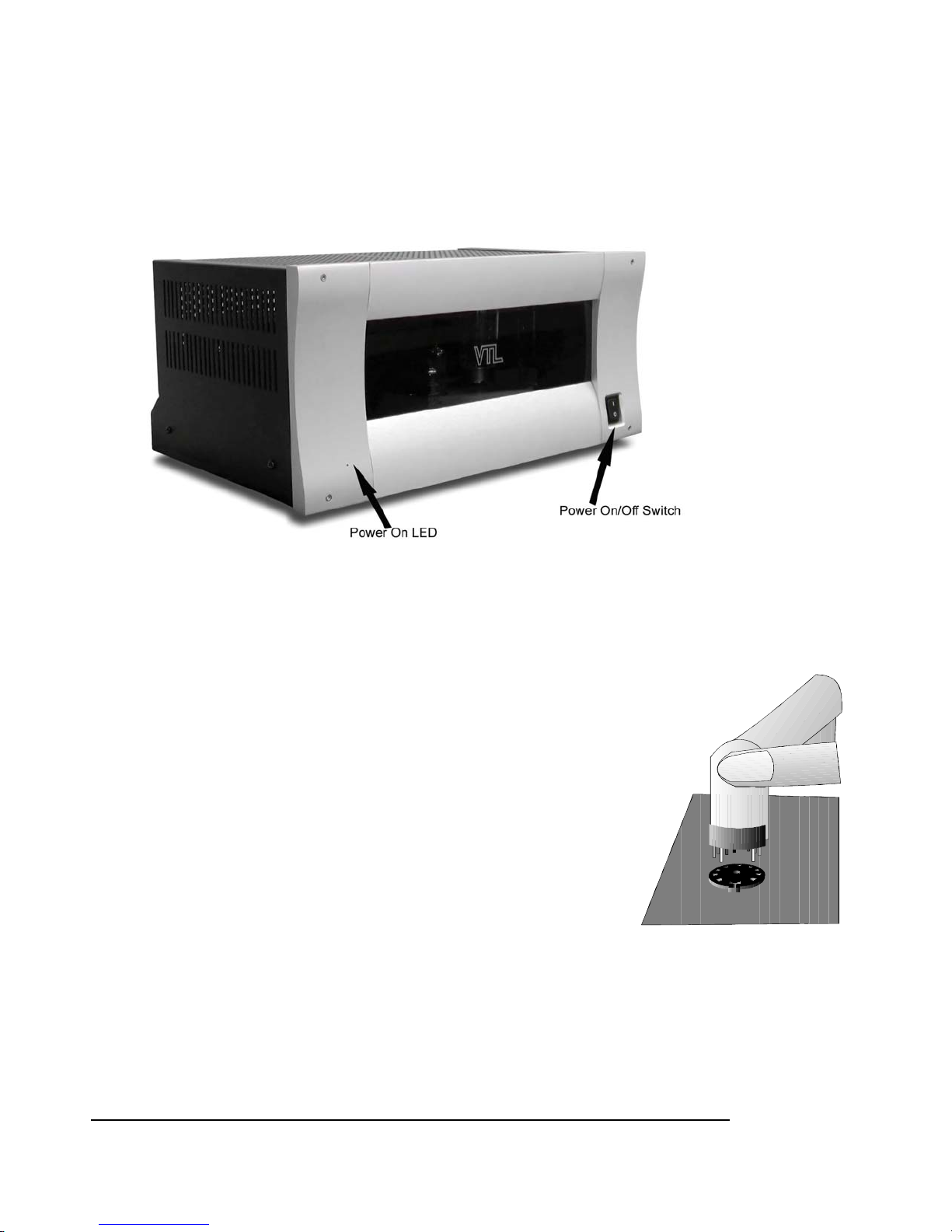
The ST-150 F ront Panel
The ST-150 Front Panel shows the Power on switch and the power on LED indicator.
Check for tube placement
Use the following procedures to check whether the tubes standing on the deck of your amplifier are placed
firmly in their sockets, as the tubes can become dislodged and loosen during shipping or unpacking of the
amplifier.
Visually inspect through the vent holes to ensure that all tubes are fully seated before
powering the unit on for the first time. If there are any tubes not fully seated then you
should refer to your VTL dealer, and take this procedure with the amplifier.
Notes for the servicing technician:
1. Remove the protective wire cage on the top deck of the amplifier. The
cage is mounted with three screws on each side of the amplifier as well as 2
hex screws on the top portion of the front panel. Use a 7/64” hex wrench
to remove the hex screws from the top of the front panel. Loosen the side
screws and lift the wire cage slowly and carefully. Do not let the cage
touch or hit any of the tubes inside the amplifier. Keep the cage and the
screws in a separate place while you’re working on the amplifier.
2. Make sure that the amplifier is not connected to the power outlet and not
turned on. Use your fingers to hold onto the upper portion of the tube towards its tip. Gently
rock the side of the tube to see if there is any movement in the tube. If there is any movement,
that means the tube has come loose. Press the tube firmly into its socket, using a gentle force
and a slight “rocking” motion.
3. Repeat the above test for the rest of the tubes. There are a total of eight output tubes and four
input tubes in each amplifier.
ST-150 Owner’s Manual
VTL
4
Page 10
4. After you’ve examined all the tubes to make sure that they are firmly placed in their sockets, you
can put the protective cage back onto the amplifier unit. Tighten the screws to make sure that
the cage is securely fastened to the unit.
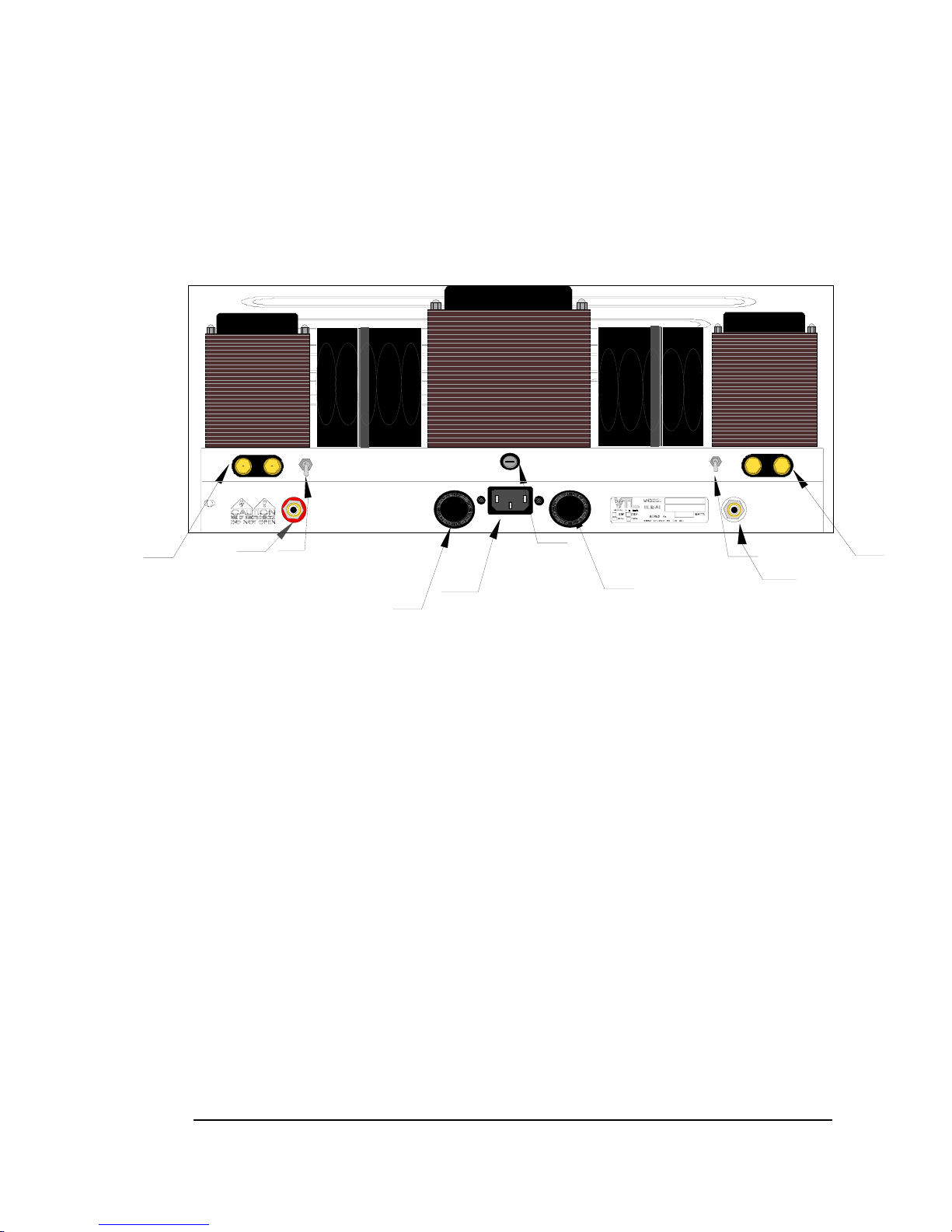
ST -150 Back Panel
Binding posts
SPEAKER
+
RIGHT CHANNEL
RCA input
TRIODE
WARNING
To prevent possible switch damage do not change mode
while amplifier is powered on.
-
TETRODE
To prevent electrical shock do not remove cover.
No user servicable parts inside. Refer servicing
INPUT
to qualified personnel. For continued protection
against fire hazard replace only with fuses of same
type and rating. To prevent fire or shock do not
expose this appliance to rain or moisture.
Triode/Tetrode switch
To prevent possible transformer
on before making all connections.or speaker damage do not power
B+ fuse
1A F 600V
F
U
S
E
E
S
U
F
F
U
S
E
AC POWER
AC receptacle
MAIN FUSE
8A(120VAC) SLO-BLO
4A(240VAC) SLO-BLO
B+ FUSEB+ FUSE
1A F 600V
F
U
S
E
E
S
U
F
F
U
S
E
Stereo Power Amplifier
Mains fuse
12A(120VAC) SLO BLO
6A(240VAC) SLO BLO
B+ fuse
1A F 600V
TRIODE
TETRODE
Triode/Tetrode switch
SPEAKER
+
LEFT CHANNEL
INPUT
Manufactured by:
Vacuum Tube Logic
4774 Murrieta Street
Suite 10, Chino, CA
91710, USA (909) 627-5944
RCA input
-
Binding posts
1A F 600V
The ST-150 Back Panel Silkscreen
Connecting Y our Amplifier to your system
The ST-150 Stereo amplifier is a self-contained unit with the amplifier and power supply sections on one
compact chassis. Follow the instructions below to connect the amplifier to your audio or home theater
system:
1. Connect all source components (e.g. CD, Tuner, Tape, DAT, Turntable etc.) to the preamplifier.
Follow the instructions on your preamplifier and source component manuals to connect these
components together.
2.
Connect the power amplifier to the output channel of the preamplifier. The interconnect cable
between the amplifier and the preamplifier links the input channel of the power amplifier to the output
channel of the preamplifier. Connect the Left Channel RCA Jack from the Stereo amplifier to the left
output channel of the preamplifier. The same applies to the right channel of the amplifier.
3.
Select the input connector type. The amplifier supports only one type of input connector – the RCA
input. Place the interconnect cable firmly into the input jack which matches the type you have, and firmly
insert the interconnect cable into the input jack marked “INPUT”.
Connect the loudspeaker cable to your amplifier. There is a pair of speaker binding posts in the back
4.
of your amplifier for connecting your loudspeaker cables to the amplifier. These binding posts are marked
ST-150 Owner’s Manual
VTL
5
Page 11

“+” and “-” above the posts and “SPEAKER” in between the posts. For example, if you are connecting
the Stereo amplifier to the left channel speaker, you should take the speaker cable connected to the left
speaker and connect it to the amplifier’s “LEFT CHANNEL SPEAKER” binding posts. First, loosen
the binding posts on the amplifier. Take the red connector from the speaker cable and connect it to the
“SPEAKER” binding post marked “+”. Take the black connector from the speaker cable and connect it
to the “SPEAKER” binding post marked “-“. Tighten the binding posts by hand, using a nut-driver
(3/8”). Be careful not to over-tighten the posts, as you may break the connection inside the amplifier if
you exert too much force on the posts.
V oltage Setting
Your power amplifier voltage has been set by the factory, for the country where you made your purchase. The
voltage setting should be marked on the Serial Number Badge located on the back panel of your amplifier.
Check to make sure that this complies with your local voltage rating before plugging in and turning on your
amplifier.
Your amplifier is shipped with a power cord that matches the requirements of your country. If you need
a replacement and you are not sure what the appropriate cord should be, consult your authorized VTL
dealer or the VTL factory customer support department.
Pow er Source for your Amplifier
Your ST-150 Stereo power amplifier is a high-performance, high power amplifier capable of outputting up to
150 watts per channel. To assure that you can operate your power amplifier under the best conditions, for
optimal results, you should plug the unit directly into a wall AC outlet, preferably one separate outlet for each
unit. Do not plug your amplifier into a light extension cord or into the back of another component. This will
starve the amplifier of current and significantly impact the performance of your system.
See the chapter on
Specifications for the power consumption requirements of your amplifier.
ST-150 Owner’s Manual
VTL
6
Page 12

CHAPTER 3
Operating the Amplifier
Pow ering your system on
After you have properly connected your loudspeakers to your power amplifiers and all your source
components and the power amplifiers to the preamplifier you are ready to power your system on.
1. If you haven’t already done so, visually (by looking through the cage vent holes) ensure that all the tubes
inside the VTL amplifier are properly seated all the way into their sockets. Make sure that the power
amplifier is not powered on at this stage by either disconnecting it from the AC source or turn the power
on switch on the front panel of the amplifier to the “off” or “0” position.
2. Power on the source component(s) you intend to use for your listening session
3. Power on your preamplifier. Make sure that your preamplifier is either in the mute state or turn its volume
knob to the zero position.
4. Using the power cord which comes with your amplifier, connect the one end of the power cord to the
“AC POWER” connector on the bottom angle of the back of the amplifier. Connect the other end of the
power cord to an electrical outlet directly into a wall socket.
5. Turn on the power amplifier in your system. The power-on switch is located on the right hand corner of
the amplifier’s front panel. When the unit is powered off, the switch points in the “0” position. Clicking
the switch down turns on the unit and the switch is in the “1” position. There is a power-on LED to the
left of the front panel. The LED light should be on when the system is properly powered on.
ÎCaution: When you turn on your amplifier for the first time, watch the tubes while they warm up and
observe if any of them goes into an exceptionally bright red glow on the plate of any of the tubes. Turn
the system off immediately and refer to your authorized VTL dealer or the VTL factory service dept. if
this happens. This glow may indicate a defective tube that needs to be replaced.
ÎCaution: If powering on the system using the above steps results in tripping a circuit breaker in your
house, or blowing a fuse on the amplifier, then turn off the power amplifier and the rest of the system
immediately. Find the fuse box and turn the circuit on again to restore power to your house. Contact
your VTL authorized dealer or the VTL factory customer support department immediately so that they
can help you resolve this problem.
Ground Loop Hum
If you get a ground loop hum from your stereo system after installation and turn on, you should immediately
turn off the amplifiers and consult your VTL dealer or the VTL factory. Under no circumstances should you
attempt to lift or defeat any grounds on electrical equipment plugged into the AC, as these grounds are installed
for your and the equipment’s safety, and an ungrounded component can present an extremely hazardous
condition and is illegal under most electrical safety codes. For your own safety please refer all questions of this
nature to a properly trained service technician.
ST-150 Owner’s Manual
VTL
7
Page 13

Pow ering the system off
1. When you’re done listening to your system always turn the amplifier off first. Locate the “Power On”
switch on the lower right hand side of the front panel of the amplifier. Turn the switch to the “0” position.
The amplifier should now be in powered-off state, and the “Power-on LED” on the left of the front panel
should be extinguished.
2. Wait at least 20 seconds after the amplifier is powered down before you proceed to turn off the other
components in your system
3. Turn the preamplifier and source components off, if you prefer to keep these off when not in use.
T etrode-Triode Switching
Your VTL power amplifier gives you a choice of listening to your system in tetrode mode or in triode mode. In
tetrode mode, your amplifier is capable of delivering up to 150 watts per channel. This mode of operation is
most suited to music that requires a wide dynamic response and lots of bass punch. Triode mode for the ST150, operating at approximately 80 watts per channel, is most suited for vocal and small instrumental
ensembles. In this mode, you will experience the delicacy, detail, and intimacy of the music in its very best
form.
ÎCaution: you must power off the amplifier first before changing the tetrode-triode setting.
After the amplifier is powered off, look for the switch marked “Tetrode Triode” in the back of the amplifier.
Flip the switch in the direction as indicated by the markings.
Power your amplifiers back on again, and your amplifier should now be operating in the mode you specified.
Bias checking and Setting
The idle (or quiescent) draw for the output tubes has been factory preset for approximately 27 mA for each
tube, and should be re-set upon initial installation into your system. This setting should only be performed by
someone trained in this procedure, as it requires removal of one of the covers that will expose potentially
hazardous voltages, which are present in the unit. Do not attempt to undertake this procedure yourself as you
could be injured. The idle current of the tubes will fluctuate slightly over time at a rate that is dependent on the
usage of the unit. We recommend that the bias setting should be checked on all the tubes after
every 1000 hours of listening (or once per year.)
settings will result in poor performance and a shortened lifetime for the tubes.
There is a fuse on the back panel of the amplifier that will protect the rest of the circuitry in the event that a
tube draws excessive current. If the fuse blows then you should immediately turn the amplifier off and contact
your authorized VTL dealer or the VTL factory customer support department before attempting to turn the
amplifier back on again. The symptom for this fuse blowing is either a condition where all the tubes appear to
be lit but with no sound coming out of the amplifier, or a tearing sound coming from your speaker if the fuse
blows while the amplifier is playing music. This sound will not damage your loudspeakers as the amplifier is
losing power while the fuse is blowing, and its level is not changed by the volume control position of the
preamplifier.
Using your amplifier with incorrect bias
ÎCaution: Bias checking and setting on all tubes must be performed every time a tube is
replaced in an amplifier.
For checking the bias you should take the unit and this procedure to your authorized VTL
ST-150 Owner’s Manual
VTL
8
Page 14

dealer and ask them to check the bias for you.
Notes for the service technician:
Bias measurements are preferably taken with a digital multimeter equipped with the auto-ranging feature. If
you don’t have such a meter you can purchase one at a local electronics supply store such as Radio Shack. The
Radio Shack catalog numbers for usable multimeters are: 22-166, 22-167, 22-163, 22-174 or even 22-179.
Use the following procedures to measure and adjust the bias setting:
1. Make sure that the amplifier is powered off. To remove the protective cage, use a 7/16 hex
wrench to remove the top two screws of the front panel and a #2 Phillips screw driver to
remove the four round head Phillips screws on the left and right side of the cages. Remove the
protective metal cage of the amplifier, and make sure that there is sufficient room around the
amplifier for you to access the bias measurement points going across the front of the amplifier.
Set the multimeter for resistance measurement (ohms). (Consult the multimeters' owner’s
manual to make sure that you have used the correct settings.)
2. Connect the negative (black, “-“) probe from the multimeter to the ground point on the deck.
3. Consult the following figure for the locations of the bias measurement points on the amplifier’s
top deck. Insert the positive (red, “+”) probe of the multimeter into each bias measurement
point. The resistance reading on each point should be 10 ohms, within a 10% range. If the
resistance reading is outside the acceptable range, please consult the VTL factory customer
service department immediately. Repeat the measurement procedure for all 4 bias measurement
points.
4. Remove the multimeter probes from the amplifier. Check to make sure that the amplifier is
connected to a loudspeaker or a load resistor. Either short the input or put the preamplifier in
the mute state (or turn the volume down) to make sure that no signal is coming from the
preamplifier. Power on the amplifier and let it warm up for about 10-15 minutes so that the
tubes become stabilized.
5. Change the meter setting to measure DC voltage. Insert the negative probe (black) from the
multimeter into the negative speaker binding post of the amplifier fitting it into the post where
the speaker cable is connected. Insert the positive probe into the bias measurement point of
each tube going from the #1 point to #4. The reading on the multimeter should stabilize after a
second or two and indicate a reading between 275 to 300 millivolts DC (0.275 to 0.300 Volts.)
This reading may fluctuate a little due to variations in the AC lines. It is not unusual for a 120V
rated AC line to vary between 115V and 122 V.
6. Î Caution: If the voltage reading is 50 millivolts or more below or above the acceptable
range then adjust the trimpot in the direction required and ensure that the reading is
changing. If the reading does not respond or continues to climb rapidly, or fluctuates with
large swings back and forth then you should turn off the amplifier immediately and
contact the VTL factory service department for assistance.
7. In general a 10 - 15% variation around the 275-300 millivolts range is an acceptable bias
measurement. When the measurement is outside this range, you will need to adjust the bias
setting by using the following procedures:
1. Keep the positive probe from the millimeter in the same measurement point where you
found the out of range bias reading. Locate the bias adjustment point whose number
ST-150 Owner’s Manual
VTL
9
Page 15
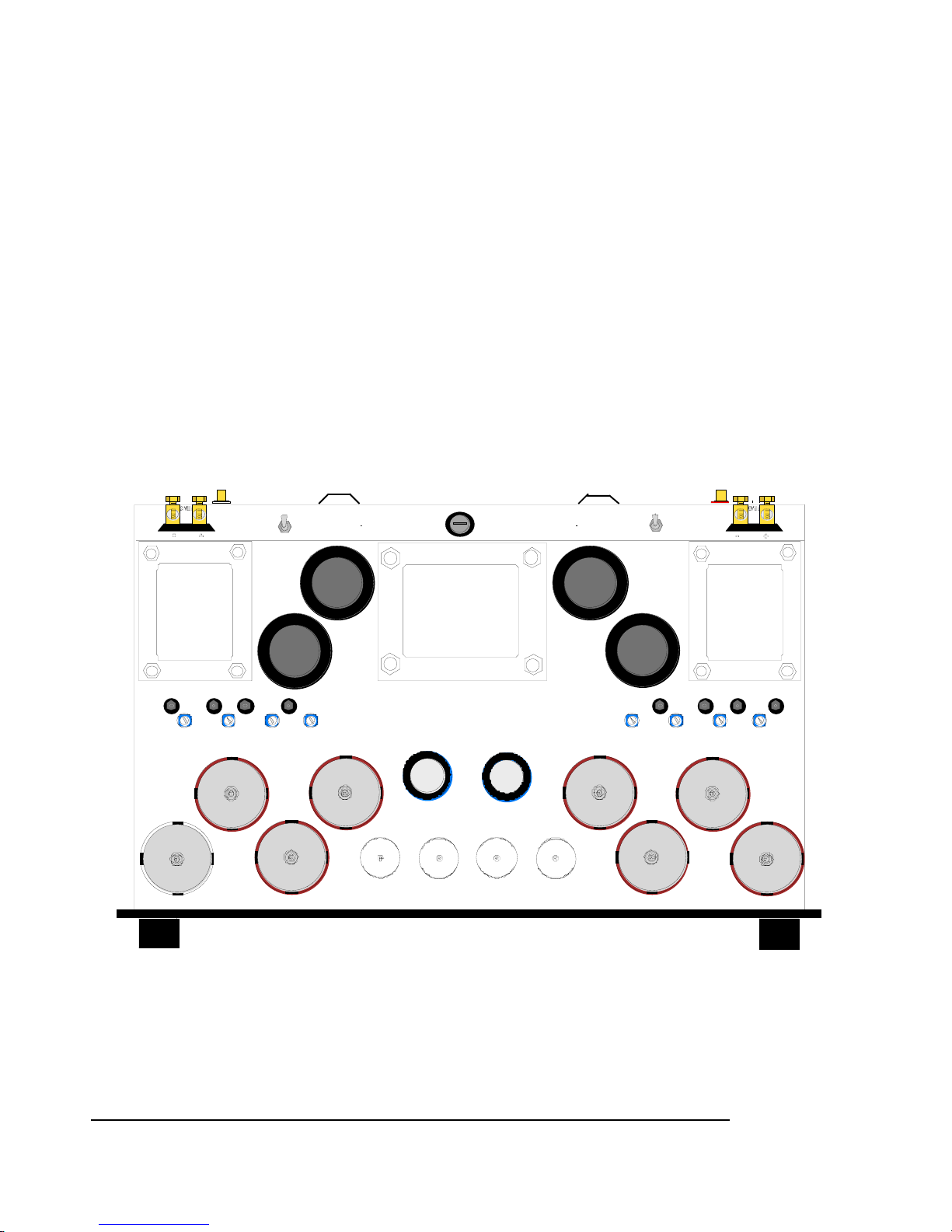
corresponds to the bias measurement point. See Figure below for the locations of the
measurement points.
2. Insert a 1/8” flat tipped screwdriver (with a plastic shaft or a properly insulated handle) into
the bias adjustment trimpot that corresponds to the out of range measurement point.
Rotate the screwdriver slowly to see the changes on the multimeter reading. Try rotating the
screw in both directions to see the effect of the change. Adjust the setting of the bias to the
proper range, i.e. 275 to 300 millivolts DC.
3. After you’ve completed the bias adjustment changes, it is a good idea to go back and check
the bias measurements for all the other tubes since changes made to one tube will slightly
affect the setting of the others.
4. Place the amplifier’s protective cage firmly back onto the amplifier after you are satisfied that
the measurements are stable.
ÎCaution: If your observations do not conform to the above instructions, or if you do not feel confident
about performing the bias procedures yourself, please consult with the VTL factory service
department. Improper setting of the bias will affect the current draw of the output tubes and affect
the performance and lifetime of the tubes.
Top view and Bias Measurement points of the ST-150 Amplifier
MEASUREMENT POINT
BIAS ADJUST POINTS
2
1
1
234
6550C
1
6550C
TETRODE
TRIODE
4
3
2
4
6550C
on before making all connections.
or speaker damage do not power
To prevent possible transformer
WARNING
4A(230VAC) SLO-BLO
8A(115VAC) SLO-BLO
MAIN FUSE
WARNING
5
6550C
3
6550C
12BH7 12AT7
12AT7
12BH7
while amplifier is powered on.
damage do not change mode
To prevent possible switch
5
5
6
6550C
TETRODE
TRIODE
67
67
7
6550C
8
8
8
6550C
ST-150 Owner’s Manual
VTL
10
Page 16

CHAPTER 4
Care and Maintenance of your VTL
Amplifier
Break In Period
Your VTL amplifier is a pure tube product designed to give you the continued optimum performance over a
long time period. Even though the amplifier has undergone a burn-in cycle in the VTL factory, the tubes and
circuits will require further usage and burn-in to reach maximum performance. During the first 100 hours of
usage the amplifier will undergo noticeable improvements in sound.
Pow er-on Period
We recommend that your amplifier should be powered-off when you are done with your listening session.
Leaving your amplifiers running idle when you are not listening to music will be a waste of electricity as well as
unnecessary usage of the tube life.
Tube T ypes
The VTL ST-150 Stereo amplifier uses a total of eight 6550C tubes for the output stage and two 12AT7
and two 12BH7 tubes for the input and driver stages.
Tube Lif e
Your VTL amplifier has been designed to ensure long tube life. Tube replacement need not be considered
until after approximately 3000 hours of use (roughly 3 to 4 years depending on your listening requirements.)
As the tubes age beyond their peak performance they begin to lose their ability to provide full power. This
usually results in some loss of control in the bass and a general softening of the sound in the upper frequencies.
We recommend a complete replacement of all tubes in your amplifier at that time, which will restore it to a
“like new” sound quality. Your VTL dealer or VTL factory service department will be happy to assist you with
the re-tubing process.
Note: use only tube types and tube brands that are recommended by VTL. VTL specified
replacement tubes are available from your authorized VTL dealer or the VTL factory
service department. Any damage incurred to units which use non-VTL approved tubes will
not be covered under the warranty.
ST-150 Owner’s Manual
VTL
11
Page 17
Changing Tubes
Do not attempt to change tubes yourself. Contact your authorized VTL dealer or the VTL factory services
department so that a trained technician can perform this service. You will need to take the unit and this
procedure to your dealer for them to perform this procedure and the corresponding bias procedure properly.
Notes to the Service technician:
Be sure to only touch the tubes themselves, and do not allow any part of your body or hanging jewelry to come
into contact with any part of the circuit inside the unit.
1. Diagnose the tubes: If you are not undergoing a complete retube for the entire amplifier, then
you must first decide how many tubes and which tubes should be changed. Use the bias
checking procedure as documented in the Getting Started section of this manual to find out how
to measure the bias setting of the tubes and to determine whether they are within the acceptable
range. For example if you find out from the bias measurements that tube #1 and #3 are
fluctuating frequently and they are above or below the acceptable range this may indicate that a
replacement of these two tubes is necessary. A full power test of the amplifier may need to be
undertaken to ensure that all power tubes are conducting equally.
2. Power off the amplifier: To change tubes in this amplifier you should first power the unit down,
unplug the unit from the wall outlet and disconnect the amplifier from the rest of your system.
Let the amplifier stay power-off for at least 15 minutes before you start working with it. Make
sure the tubes are cool before you touch them. Using a Philips #2 point screwdriver remove the
protective cage from the unit by loosening the two screws from the side of the amplifier.
Carefully remove the cover and the screws and store them in a safe place.
3. Removing Tubes: Locate the tube you need to remove and hold onto the upper portion of the
tube towards its tip. Gently rotate and rock the tube with your fingers to loosen it from its socket
until its pins are completely disengaged from the socket. Take the tube out of the unit.
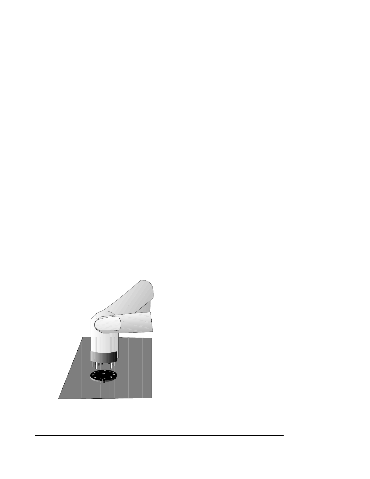
1. Plugging in a new tube: Hold onto the upper portion of the tube towards its tip. Lower the
tube onto the socket, making sure that the
pins from the tube match the holes in the
socket. There are either two pins on the
tube which are spaced at a wider distance
from each other than the rest of the pins (9
pin miniature tubes), or there is a locating
key in the middle of the tube (8 pin octal
tubes). Make sure that these locators go
into the side of the socket that matches.
Press the tube firmly into its socket, using a
gentle force and a slight “rocking” motion.
When the tube is properly and completely
inserted into the socket it should be firmly
implanted and does not give in to any
movement at all when you try to rock it.
2. Replacing the protective cage: Lower
the amplifier’s cover chassis slowly back
into the opened amplifier box, making sure that the cover is put on in the correct front and back
position. Locate the screws that were removed from the cover and put them back in the correct
holes. Tighten all screws to make sure that the cover is securely fastened to the unit.
ST-150 Owner’s Manual
VTL
12
Page 18

Changing the AC and B+ Fuses
The B+ fuse for your amplifier is rated at 1A fast acting ceramic 600V. There is also one primary mains fuse
rated at 15A Slo Blo (120Volt AC), or 8A Slo Blo (220/240 Volt AC) ceramic. The B+ fuses are housed in
two holders located on the back panel of the amplifier, and the mains fuse is housed in a separate holder also
located on the back panel of the unit. To change either fuse, make sure the unit is powered off, and disconnect
the AC power cord from the unit. Move the amplifier so that you can work with the panel in the back. The
type of fitting used for the fuses is called a bayonet fit, which describes the action needed to remove the fuse
cap. To remove the B+ fuse, locate the large fuse holder in the back of the amplifier and check to make sure
that the silkscreen indicates that this is the B+ fuse. Turn the fuse cap counter-clockwise to loosen the cap
holder until the holder can be removed easily and note that the B+ fuse will now come off with the cap. To
replace the B+ fuse, put a new fuse in the fuse cap and return the whole assembly back into the holder, making
sure that the fuse is securely lodged in the fuse cap. Install the fuse cap back into the fuse holder and turn it
until the cap is completely screwed back onto the fuse holder. Check to make sure that there are no more
threads left on the fuse holder, and that the connection is absolutely tight.
To change the Mains fuse, use a flat blade screw driver to loosen the fuse cap. Note that the fuse will also
come out with the fuse cap. To re-install the mains fuse, insert the fuse cap back into the holder, pushing it
downward while turning it in the clockwise direction to lock it in place..
WARNING: For continued protection against fire hazard only replace the fuse with the
same type and rating as was originally specified for the amplifier. If you have problems
locating the correct fuse contact your VTL dealer or the VTL factory service department.
Cleaning
Your VTL amplifier should be dusted occasionally with a damp non-abrasive cloth. You should not use any
solvents for cleaning the front panel, as this can damage the lettering and the finish. It is recommended that
you use a contact cleaner such as Pro-Gold on the input and output connectors regularly to ensure optimum
sound and proper signal conducting capability.
Transporting ST-150
If you should ever need to ship your amplifier, pack the unit with the original carton and foam. Contact your
VTL dealer or the VTL factory if you need replacement packing material.
ST-150 Owner’s Manual
VTL
13
Page 19

CHAPTER 5
Specifications
ST-150 Stereo power amplifier
Vacuum Tube Complement 8 x 6550C, 2 x 12AT7, 2 x 12BH7
Output Power
20 Hz – 20kHz, into 5 ohm load
T.H.D. 20 Hz – 20 kHz @ 150W
T.H.D. 20 Hz – 20 kHz @ 80W
Input Sensitivity @ 150 W 100V = 0.880 V
Input Impedance 130K Ohms
Optimum Load Range 2 - 8 ohms
S/N Ratio
Power Consumption Idle = 240 W
Primary Mains Fuse Rating 100V = 15A Ceramic Slo Blo
B+ Fuse Rating 1A fast acting ceramic 600V
Dimensions W = 19 inches (48cm), D = 12 inches
Weight 60 lbs. (27.22Kg) {total 75 lbs. (34 Kg)
Tetrode: 120 watts per channel
Triode: 60 watts per channel
less than 3%
120/240V = 1.0V
-95dB, 120 Hz
Full Power = 800 W
120V = 15A Ceramic Slo Blo
220/ 240V = 8A Ceramic Slo Blo
(26cm), H =9 inches (23 cm)
packed}
ST-150 Owner’s Manual
VTL
14
Page 20

CHAPTER 6
Warranty
Your VTL amplifier/amplifier is covered by a limited warranty against defects in materials and
workmanship for a period of 90 days from date of purchase by the original purchaser only when
purchased from an authorized VTL dealer. A further optional limited non-transferable five-year warranty
is available to the original purchaser only upon proper registration of ownership within 30 days of date of
first purchase. The warranty period begins on date of first sale to the end user, or one year after shipment
from the VTL factory, whichever is the earlier.
Proper registration is made by filling out and returning to the factory the warranty card attached to this
general warranty statement, along with a copy of the original sales receipt as proof of the original date of
purchase, within 30 days of purchase. Only one registration card is issued with each unit. If the warranty
registration card has already been removed then this is not a new unit, and is therefore not warranted by
the factory. If you believe this to be a new unit then please contact the factory with the details of purchase.
This warranty is provided by the dealer where the unit was purchased, and by VTL Amplifiers Inc. Under
the terms of the warranty defective parts will be repaired or replaced without charge, excepting the cost of
tubes. A six-month warranty on tubes is available with the correct recording of the serial number of the
amplifier on your warranty registration card and mailing it with your purchase receipt to VTL.
If a VTL product fails to perform properly under the above warranty then the purchaser's sole remedy
shall be to return the product to the authorized VTL dealer or to VTL Amplifiers Inc, where the defect
will be repaired without charge for parts and labor. The product will then be returned via prepaid, insured
freight, method and carrier to be determined solely by VTL Amplifiers Inc. All returns to the factory must
be in the original packing and accompanied by a Return Authorization, (new packing will be supplied for a
nominal charge if needed), accompanied by a written description of the defect. This must be shipped to
VTL Amplifiers Inc via insured freight at the customer's own expense. Charges for unauthorized service
and transportation costs are not reimbursable under this warranty, and all warrantees, express or implied,
become null and void where the product has been damaged by misuse, accident, neglect, modification,
tampering or unauthorized alteration by anyone other than VTL Amplifiers Inc., including the use of nonfactory approved tubes.
This warranty applies only to units used in residential non-commercial use. The warrantor assumes no
liability for property damage or any other incidental or consequential damage, whatsoever which may
result from failure of this product. Any and all warrantees of merchantability and fitness implied by law
are limited to the duration of the expressed warranty. All warrantees apply only to VTL products
purchased and used in the USA.
Some states do not allow limitations on how long an implied warranty lasts, so the above limitations may
not apply to you. Some states do not allow the exclusion or limitation of incidental or consequential
damages, so the above exclusion may not apply to you.
This warranty gives you specific legal rights and you may also have other rights that vary from state to
state.
ST-150 Owner’s Manual
VTL
15
Page 21

APPENDIX
Warranty Registration
Warranty registration for VTL products is valid in the USA only. International VTL customers should consult
the local VTL importer regarding product registration and warranty procedures.
To obtain valid US warranty service, please fill out the enclosed VTL Warranty Registration card and mail it
together with a COPY OF THE ORIGINAL BILL OF SALE to the following address within the first
thirty days of purchase:
VTL Warranty Registration
4774 Murrieta Street, Suite 10
Chino, CA 91710
USA
To help you keep a record of the serial number and purchase information, please enter the following
information into this manual.
Product Model Number: ___________________________
Serial Number: ___________________________
Purchase Date: ___________________________
Authorized Dealer: ___________________________
Service Notes
Date Service Initials
___________ __________________________ _____
___________ __________________________ _____
___________ __________________________ _____
___________ __________________________ _____
___________ __________________________ _____
___________ __________________________ _____
ST-150 Owner’s Manual
VTL
16
 Loading...