

VTL S-400 II series Owner's Manual

VTL
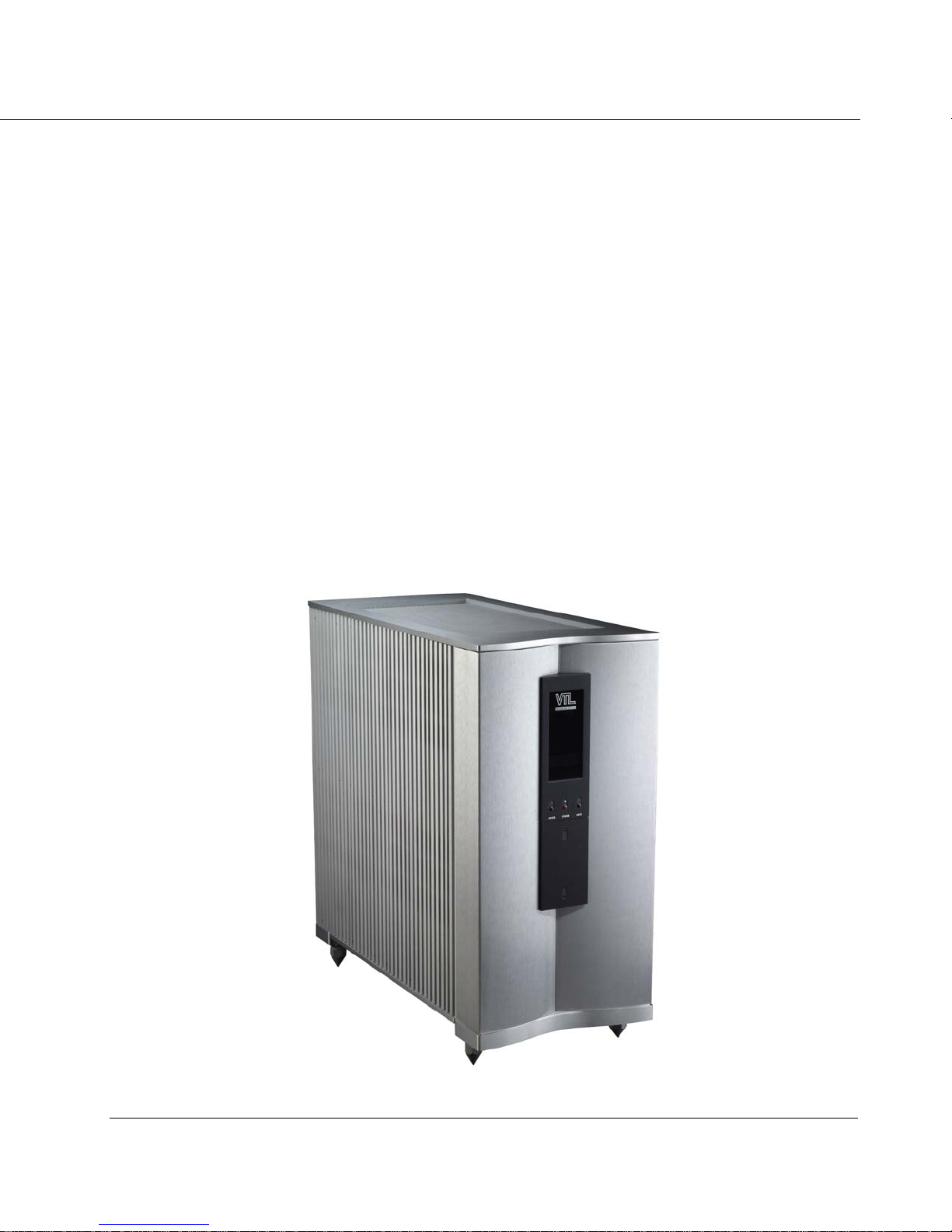
S-400 Series II Reference Stereo Amplifier
O w n e r ’ s M a n u a l

MAKING TUBES USER FRIENDLY
VTL S-400 II Amplifier
Information in this document is subject to change without notice. No part of this document may be reproduced
or transmitted in any form or by any means, electronic or mechanical, for any purpose, without the express
written permission by VTL.
Version History:
Version 1.0 August 26, 2014
Part Number: OM-S-400
Copyright © 2014 by VTL Amplifiers Inc. All rights reserved.
4774 Murrieta Street, Suite 10
Chino, CA 91710, USA
Phone 909.627.5944 • Fax 909.627.6988
Email: mail@vtl.com • http://www.vtl.com
S-400 Amplifier Owner’s Manual
VTL
i

TABLE OF CONTENT
CHAPTER 1 ......................................................................................................................................................................... 1
INTRODUCTION.............................................................................................................................................................. 1
Symbol Conventions used in this guide......................................................................................................................................... 4
Electrical Safety Notice................................................................................................................................................................ 4
Water and Moisture......................................................................................................................................................................4
Location and Ventilation .............................................................................................................................................................. 4
Servicing....................................................................................................................................................................................... 5
Operational Warnings............................................................................................................................... ................................... 5
CHAPTER 2 ......................................................................................................................................................................... 7
GETTING STARTED........................................................................................................................................................ 7
Before starting.............................................................................................................................................................................. 7
Unpacking the unit from the crate................................................................................................................................................ 7
Changing Top Cover Screws ...................................................................................................................................................... 10
Quick Start.................................................................................................................................................................................. 11
CHAPTER 3 ....................................................................................................................................................................... 15
OPERATING THE AMPLIFIER ........................................................................................................................................ 15
Rear panel controls and connections.......................................................................................................................................... 15
Rear Panel Functions ............................................................................................................................................................................................17
1. Fuse Tester ....................................................................................................................................................................................................17
2. Changing input between balanced and single-ended....................................................................................................................................17
3. Changing amplifier phase.............................................................................................................................................................................17
Front panel controls and indicators........................................................................................................................................... 18
Front Panel Controls.........................................................................................................................................................................................18
Front Panel Indicators.......................................................................................................................................................................................18
AC Voltage Setting...................................................................................................................................................................... 19
AC Power Source........................................................................................................................................................................ 20
Connection to the AC........................................................................................................................................................................................20
Powering On the Amplifier......................................................................................................................................................... 20
Ground Loop Hum...................................................................................................................................................................... 23
Setting the Operating Mode........................................................................................................................................................ 23
Muting the Amplifier................................................................................................................................................................... 24
Tube Bias and Top deck Indications........................................................................................................................................... 24
Using the DF switches................................................................................................................................................................ 27
DF Switch Settings ..........................................................................................................................................................................................27
Remote Control and Communications........................................................................................................................................ 29
Using a 12V trigger to power the amplifier on or off.......................................................................................................................................29
Using the Amplifier with an infrared Remote Control.....................................................................................................................................29
Using the amplifier with RS232 control...........................................................................................................................................................30
Diagnostic and programming Functions.................................................................................................................................... 32
Basic Programming functions...........................................................................................................................................................................32
Basic Diagnostic functions ...............................................................................................................................................................................34
Advanced Functions and Diagnostics...............................................................................................................................................................37
Fault Indications......................................................................................................................................................................... 39
Not ready modes....................................................................................................................................................................................................39
INVERTed Phase..................................................................................................................................................................................................40
TUBE green Fault.................................................................................................................................................................................................40
TUBE red Fault.....................................................................................................................................................................................................41
HEAT Fault...........................................................................................................................................................................................................42
POWER faults.......................................................................................................................................................................................................43
Tube Service Reminder.........................................................................................................................................................................................44
Reset / Clearing faults ................................................................................................................................................................ 44
Powering the amplifier off.......................................................................................................................................................... 45
CHAPTER 4 ....................................................................................................................................................................... 47
S-400 Amplifier Owner’s Manual
VTL
ii

CARE AND MAINTENANCE OF YOUR VTL AMPLIFIER.................................................................................................. 47
Break In Period .......................................................................................................................................................................... 47
Tube Life..................................................................................................................................................................................... 47
Changing Tubes.......................................................................................................................................................................... 48
Changing the Screen, Plate, Logic, B+ Input, Filament Fuses .................................................................................................. 51
Cleaning ..................................................................................................................................................................................... 52
Troubleshooting............................................................................................................................... ........................................... 52
CHAPTER 5 ....................................................................................................................................................................... 55
SPECIFICATIONS .......................................................................................................................................................... 55
CHAPTER 6 ....................................................................................................................................................................... 57
WARRANTY................................................................................................................................................................. 57
APPENDIX......................................................................................................................................................................... 58
Appendix I: Quick Reference - Summary of indicators.............................................................................................................. 58
Appendix II: Individual tube hour log ....................................................................................................................................... 60
Warranty Registration................................................................................................................................................................ 61
Service Notes.............................................................................................................................................................................. 61
S-400 Amplifier Owner’s Manual
VTL
iii
CHAPTER 1
Introduction
Congratulations on your purchase of the VTL S-400 Series II Reference Amplifier – the modern vacuum tube amplifier
designed to bring high performance and ease of use to serious music lovers such as yourself.
From all of us at VTL, we are proud to offer our S-400 Series II Reference power amplifier – the ultimate expression of
everything we know about power amplifier design, designed to deliver the most advanced technology and thinking in
power amplifier design today. S-400’s bold and ultra fast sound and commanding vocal and visual presence are
appreciated by the most serious and discerning music and film lovers. We thank you for selecting this amplifier for your
home audio/theater system, and we wish you many hours of enjoyment for years to come.
In order to get the most benefit from your purchase, we recommend that you take sufficient time to familiarize yourself
with the features of this product. Please take a moment to read through this owner’s manual, as it contains all of the
installation procedures needed to connect your new amplifier to the rest of your system, as well as the many functions
that the amplifier can perform. After you have finished reading this manual it should be kept in a safe place for future
reference.
S-400 Amplifier Owner’s Manual
VTL
1

The Design Goals and Benefits
When the VTL design team began developing the concepts for a next-generation Reference amplifier, the following
design goals were laid out:
• The Reference amplifier should deliver a new sonic standard worthy of its marque as a member of the VTL
Reference family – it should provide unsurpassed sound quality into real-world loads, as well as excellent
measurements on the test bench
• The amplifier must be able to drive a wide range of speaker types to their optimal performance, with
consistent performance under a wide range of conditions
• The amplifier must be self-optimizing and provide a full range of diagnostics for maintaining peak
performance and providing user feedback, without the need for the user to have to know the inner workings
of the amplifier.
• The operation of the amplifier must be intuitive and user-friendly while providing flexibility in its control
functions, for integration with modern home theater systems
• Complete in-system diagnosis via front panel or remote to make remote use and maintenance easy.
These goals have been fully realized in the new S-400 power amplifiers.
S-400 Series II Circuit overview:
An all-tube amplifier, S-400 is the culmination of VTL’s most advanced thinking in performance engineering, with selfoptimization, fault diagnosis and user feedback designed to bring the ultimate performance and convenience to the
user.
The Series II version of the S-400 features a complete re-working of the entire signal path. Upgrades include a fully
balanced differential input stage driving a differential phase splitter and a lower impedance push-pull output stage with a
dramatically improved, fully balanced and enhanced interleaved and coupled output transformer.
The S-400 Reference stereo amplifiers gain further sonic benefits with a shorter, faster and fully balanced negative
feedback loop, with zero global negative feedback. The negative feedback loop completely eliminates ringing and
requires no capacitor compensation to maintain critical phase integrity and information. The result is an amplifier that
remains stable even under the most demanding loads.
Adjustable precision-regulated plate, screen and bias supplies hold the output tube operating point constant even under
AC and main power supply fluctuations, and stabilizes the critical power supplies yielding tonal stability and sonic
integrity especially during complex, dynamic signal conditions.
Another new feature in Series II is a user adjustable Damping Factor feedback control that allows the user to adjust the
amplifier’s output impedance by varying the amount of negative feedback. Impedance can now be precisely set to suit
the listener’s taste, and to improve control of the loudspeaker loads to deliver best performance. The three possible
settings are:
1. LOW -- Lowest damping factor, good loudspeaker control, most natural sound.
2. MED -- Better loudspeaker control, with some impact on sound quality
3. HI -- Best loudspeaker control, with a little more impact on sound quality, but on speakers that need the
control the sonic improvement is clear
S-400 Amplifier Owner’s Manual
VTL
2

Tube life is dramatically extended by optimized operating voltages and timed, low current inrush limiting, with low idle
current draw on all stages. An ever-warm position further lowers idle current and keeps all voltages present to keep the
circuit warm when not in use.
Comprehensive fault sensing monitors internal and external conditions, protects the circuits, and alerts the user under
any adverse conditions.
In the case of any malfunction of any of the output tubes the amplifier is shut down to protect
the circuitry and faults are indicated on the front panel, along with the blinking LED on the top deck next to the tube
that caused the fault shutdown, to make diagnosis and tube replacement easy.
The logic-controlled automatic bias system is designed to keep the tubes at peak performance and operates completely
outside of the signal path.
The tube biasing circuit checks and adjusts the tube bias values automatically during the
power on sequence, as well as when the amplifier is at idle (i.e. when no music signal is being amplified.) and drops out
of the circuit path when music signal is detected.
S-400 Amplifier Owner’s Manual
VTL
3
Symbol Conv entions used in this guide
Certain symbols are used in this owner’s manual to draw your attention to important points being discussed.
For your own safety and that of your equipment you should note and heed the warnings that follow these
symbols.
The “Warning - Pay particular Attention” symbol used is
And the “Warning – Observe These Precautions for Your Safety” is
Electrical Safety Notice
Electrical voltage from power cables can be hazardous. We recommend that the
power cord used with this unit be connected to a properly grounded AC outlet.
There are hazardous voltages present in the unit, and to prevent electrical shock, do not
remove the cover of this amplifier, and under no circumstances while the unit is
powered on.
Warning – Under no circumstances should any attempt be made to
circumvent the ground system to the AC line for any reason
ground lifted system can be potentially extremely dangerous, both to persons that might
come in contact with the unit, and to the unit itself, and proper RF shielding cannot be
attained without a secure ground connection.
. Using a
Damage to the unit that is the result of improper AC connection and grounding will not be covered under the
warranty.
Prior to connecting this amplifier to any audio or video equipment in your system, make
sure this unit’s power (and the rest of the equipment connected to its input and output
channels) is turned off. Adding or removing input or output cables to the amplifier while
the system is powered on can cause damage to the amplifier and possibly also to the rest of
the system.
Water and Moisture
The amplifier should be kept away from sources of water or moisture. If liquid enters
the unit it must be immediately returned to your dealer for servicing. In this case you
should under no circumstances try to power the unit on - there are hazardous
voltages present in this unit that can cause serious injury if they come in contact with
you.
Location and V entilation
Warning – To avoid risk of failure due to overheating, do not stack chassis
components
S-400 Amplifier Owner’s Manual
VTL
4
The amplifier emits heat and needs proper ventilation to ensure long operational life.
Ensure that the amplifiers are installed in a location that is stable and well ventilated. If the
amplifier is placed in a built-in installation, ensure that there is adequate room for air to flow
through the ventilation openings. Allow at least 12 inches clearance on the top and around
the sides of each chassis of each amplifier. The warranty does not cover units that are
damaged due to overheating from incorrect installation.
Tiptoes or other isolation accessories may prove useful in reducing mechanical vibrations or other external
vibrations that might affect sonic performance, and we have found that such accessories can offer definite
beneficial sonic improvements when used correctly. In all cases you should be sure to install this amplifier in a
location that is stable, as warranty does not cover damage due to the unit falling.
Do not place the amplifier next to heat sources such as radiators, stoves or other appliances.
Do not place the amplifier where small children might be able to tamper with the equipment. If it is not possible
to place the amplifier out of the reach of small children it is recommended that you remove power cables when
the equipment is not in use.
Servicing
Do not attempt to service the amplifier beyond the procedures described in this manual.
For all other service and questions, please contact your authorized VTL dealer or the
factory.
Operational Warnings
It is critical for proper sonic performance of this component that it be properly
configured for the mode of operation while playing. If a balanced signal is
applied to the inputs the amplifier must be configured for balanced operation,
and vice-versa.
Always make all connections before powering the amplifier on. Connecting or
disconnecting the amplifier while powered on can damage the output stage, and will
not be covered under the warranty. Ensure that no interconnect cables can become
loose during use and that there are no intermittent faults with the cables.
Warning: The S-400 Series II amplifier is a fully balanced design with a balanced output.
Care should be taken so that neither output is ever grounded.
Warning: Do not connect a sub-woofer to the output of the amplifier unless you are sure
that the subwoofer input is fully balanced and that neither phase can become
grounded.
Please consult your authorized VTL dealer or the VTL factory customer support department if you have any
questions on the fully balanced connection of the amplifier.
S-400 Amplifier Owner’s Manual
VTL
5
Do not attempt to disassemble the amplifier chassis or remove any covers from
the amplifier. Always consult with your VTL authorized dealer or the VTL factory
support department before attempting any service work on any VTL unit.
Do not touch the tubes after the amplifier is turned on. Tubes can get very hot while
the amplifier is operating. Turn off the amplifier and allow the tubes to cool down before
attempting to work with the tubes.
Tube components can be heavy and awkward to lift, with the weight unevenly distributed,
and you should not attempt to move the unit without help. The amplifier weighs
approximately 250 lbs. (113 Kg).
Do not exceed fuse ratings or attempt to bypass any fuses, as this can cause an
extremely hazardous condition and will void any warrantees. Use only the same type
and rating of fuses as specified in the owners’ manual and marked on the unit.
S-400 Amplifier Owner’s Manual
VTL
6
CHAPTER 2
Getting Started
Before starting
1. This amplifier is shipped with one stereo in each crate. Inside the crate the amplifier is wrapped in thick
plastic. The plastic is not strong enough to support the unit, and may tear if you try to lift the unit out of
the box with it. Also there are protruding switches, which could break if the
unit is not properly handled, and in addition to the awkward, unbalanced heavy
load the unit has sharp edges and a cleaning polish on it, which makes it
slippery and hard to grasp.
2. When lifting the unit, be sure to enlist the help of one or more person(s) to help you. Lift from the
bottom of the unit with both hands. Be careful not to break any switches or to rest the unit on any side
other than the bottom side, and on a stable surface. Setting it on any other side may damage protruding
components.
SAVE THE CRATES AND ALL PACKAGING FOR FUTURE SHIPMENT.
Warning: This unit is extremely heavy, and weighs about 200 lbs. Unpacking
should be done by two or more people who are capable of lifting a heavy load.
Ensure that the amplifier would not fall and injure someone. Do not attempt to
lift the unit yourself.
Unpacking the unit from the crate
1 crate comes with an accessory cover and 1 crate
does not have the accessory cover.
Before the crate with the accessory cover can be
removed from the base, the top accessory cover
must be removed.
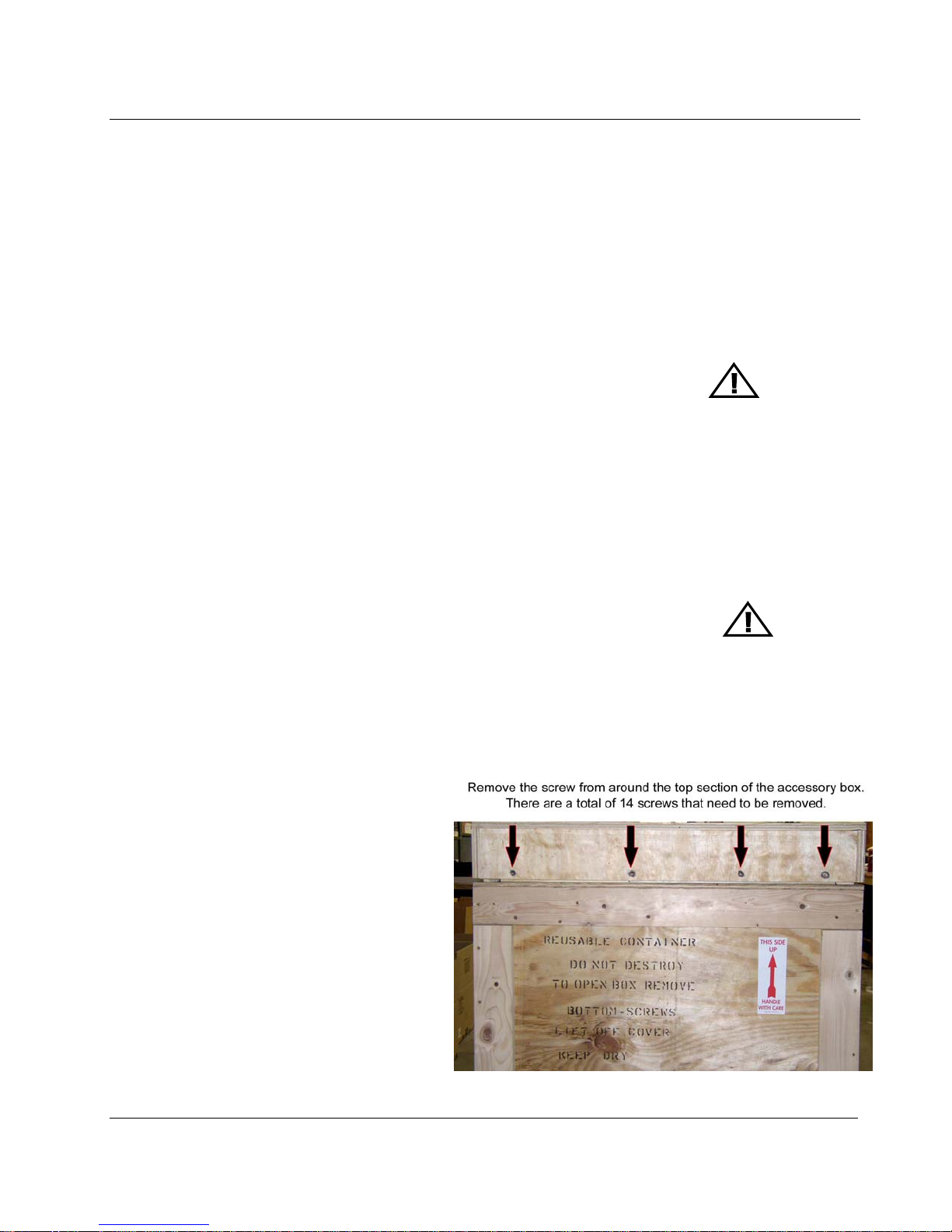
Start by removing all of the screws from around the
top of the crate. There are 14 screws in all that must
be removed before the top accessory cover can be
separated from the crate.
Place the screws in a safe place like in a plastic bag
or box.
S-400 Amplifier Owner’s Manual
VTL
7
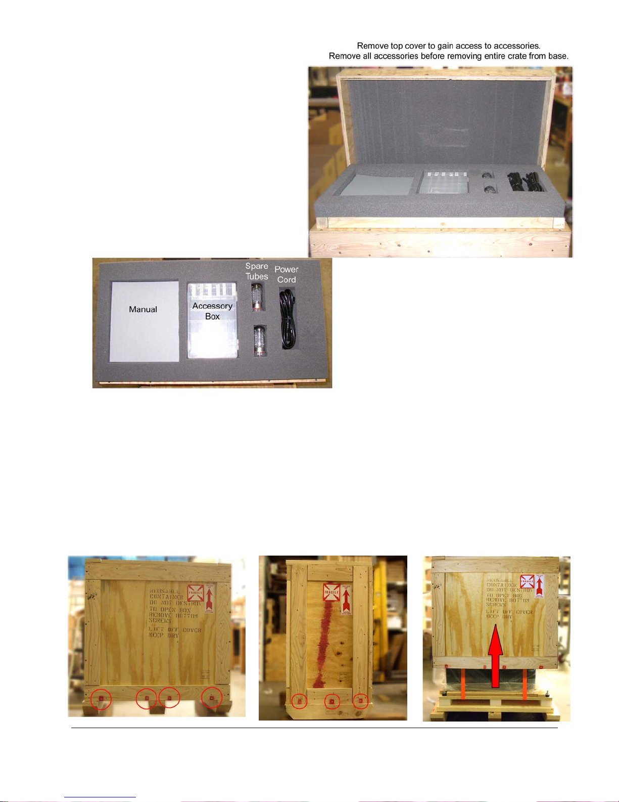
Once all of the screws are removed, the top
accessory cover can be lifted off of the crate.
With the help of someone else, lift the top
accessory cover off of the crate and set aside
for the time being.
After opening the top cover of the crate, you should find the following items inside:
• 4 6-32 x 3/8” socket head screws
• 2 6-32 x 3/8” flat head screw
• 1 standard 20A power cord for the electrical system in the country of operation
• Spare Fuses and spare output tubes
• 1 set of four spiked feet for each amp
• This Owner’s Manual, Quick Reference Sheet, VTL Quality Assurance and test printout, and a VTL product
warranty registration card
(The following sets of instructions apply to both crates from this point on.)
After removing the top accessory cover, then you may proceed with removing the screws from around the
bottom of the crate (all 4 sides, total of 14 screws), and removing the crate box by lifting it straight up over
the amplifier as shown in the following pictures, then proceed with the rest of the unpacking process.
S-400 Amplifier Owner’s Manual
VTL
8
Remove each item from its packaging material and put aside for
future use.
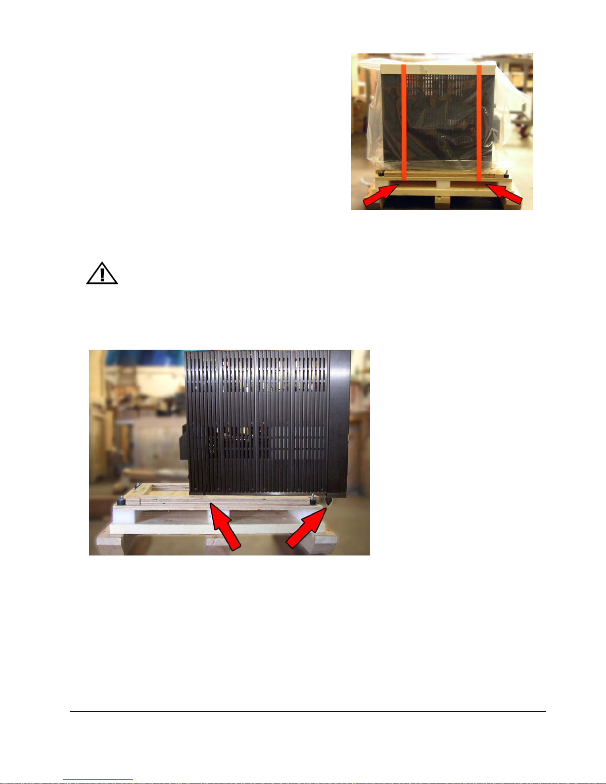
3. Remove the tie straps from the unit. Press the release
button on the strap tightener and the straps will loosen
up. Completely loosen the straps and remove them.
4. Open the plastic bag and pull it down around all sides of the unit, completely exposing the unit.
5. With at least two people, lift the amplifier clear of the bag and the crate bottom, and place the unit on a
carpeted floor on the two aluminum feet.
WARNING:
internal components of the unit.
Do not lift the unit by the heat sink or you may cause damage to the
6. If you wish to install the spiked feet on the bottom of the amplifier, remove the 4 spiked feet from the
Spare Parts kit that was included with this unit. Tilting the unit to one side at a time, install the feet into
the threaded holes in the aluminum base of the amplifier, in the approximate locations pictured.
5. Return the plastic bag and the tie straps to the base of the crate, place the crate box onto the base and
screw it together with the same screws that were removed during unpacking. Keep the crate in a safe place
for future shipping.
Check to make sure that no physical damage has occurred during shipping of the unit. There should be no
rattles inside the amplifier chassis. Look through the top cover and check to see that the tubes appear
properly seated in their sockets, and that no tubes are white on top. Contact your VTL dealer immediately
if any physical damage is detected.
S-400 Amplifier Owner’s Manual
VTL
9
Changing T op Cover Screws
When the amplifier is first shipped from the factory, the top cover is installed with locking screws. These screws can be
removed and replaced once the amplifier is setup in the listening area so that the top cover can be removed easily
without any hand tools.
Once the locking screws are removed, please put them in the Spare kit that came with the amplifier. You will need to
put these screws back when shipping or moving the amplifier to ensure that the top cover is securely fastened.
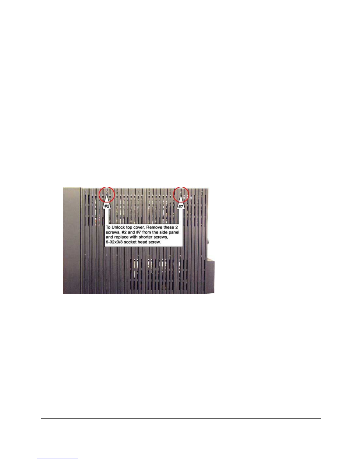
The top cover of the amplifier is fitted with long screws (6-32x5/8 Phillips head and 6-32x7/8 socket head) in three
strategic locations along the top cover. To remove the top cover, these three screws must be removed first. Two of the
long screws (socket heads) are located on the right side panel, screw #2 and #7 counting from the side closest to the
front panel. The third screw (Phillips head) is located on the top right hand corner of the back panel.
After the three long screws are removed, gently lift up the top cover. Enclosed in the spare package are the shorter
replacements screws. Replace the right side panel #2 and #7 screws with two 6-32x3/8” socket head screws. Replace
the back panel screw with the 6-32x3/8” flat head screw. Tighten the screws without overdriving them. Put the top
cover back onto the amplifier. You can now remove or replace the top cover easily without using any tool.
WARNING: there are high temperatures and hazardous voltages inside the
unit. If any household members might accidentally be exposed to these
temperatures or voltages, then the cover shipping screws should be left in
place to prevent accidental removal of cover.
S-400 Amplifier Owner’s Manual
VTL
10
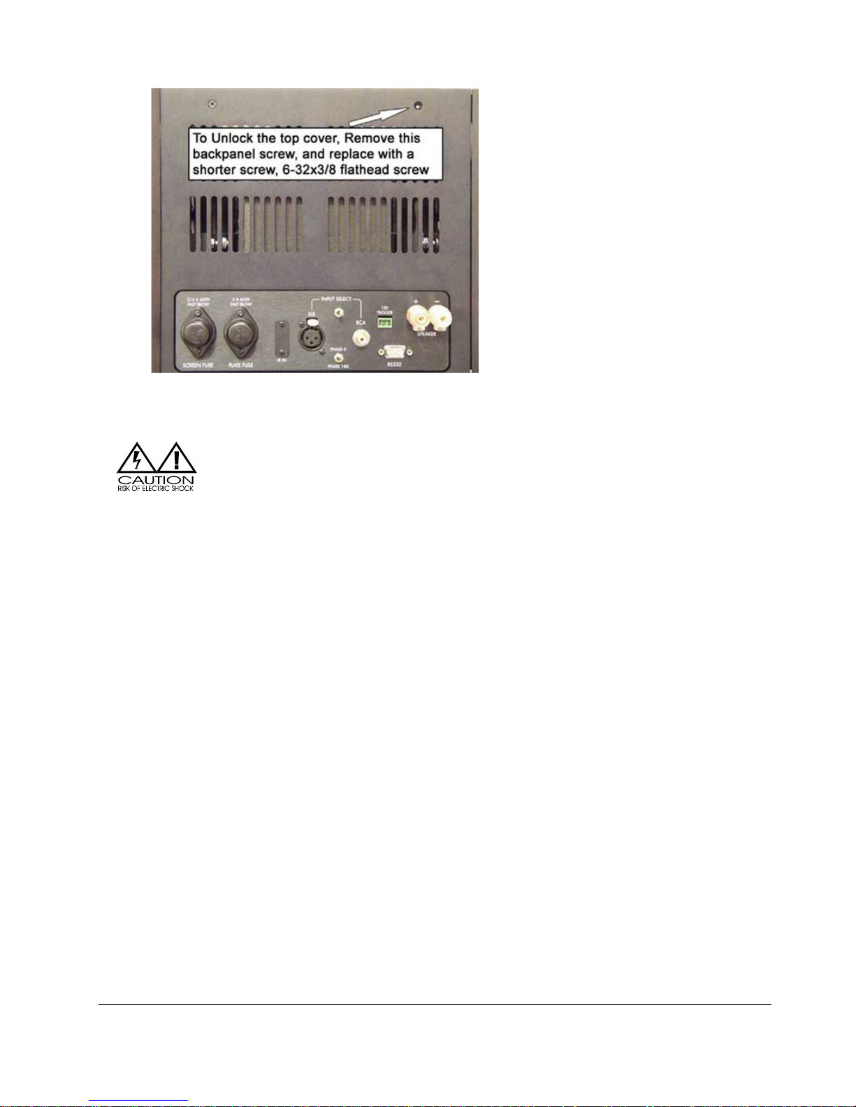
Locations of the Top Cover Screws on the back and side of the Amplifier
Opening the protective cover can expose potentially lethal voltages. Be sure
to remove the top cover screws when the amplifier is turned off, and do not
allow any part of your body or hanging jewelry to touch the inside of the
amplifier.
Quick Start
As the proud owner of your new amplifier, you are probably keen to connect it into your system and listen. This section
is a quick setup-up guide to help you get started in the shortest time possible.
Once the amplifier is in your system and operational, please take the time to read the rest of the information in this
manual. It will give you the in-depth perspective into all the functions your amplifier is capable of delivering and how
to take advantage of the many sophisticated functions built into your amplifier to inform you of its internal status.
Step 1: Find a location for the unit.
We recommend that this amplifier be placed in a stable, dry location that is well ventilated. Note that for proper
ventilation the amplifier requires sufficient air space on top as well as around its sides.
Briefly check into the cage and ensure that no tubes are out of their sockets or white on top.
S-400 Amplifier Owner’s Manual
VTL
11
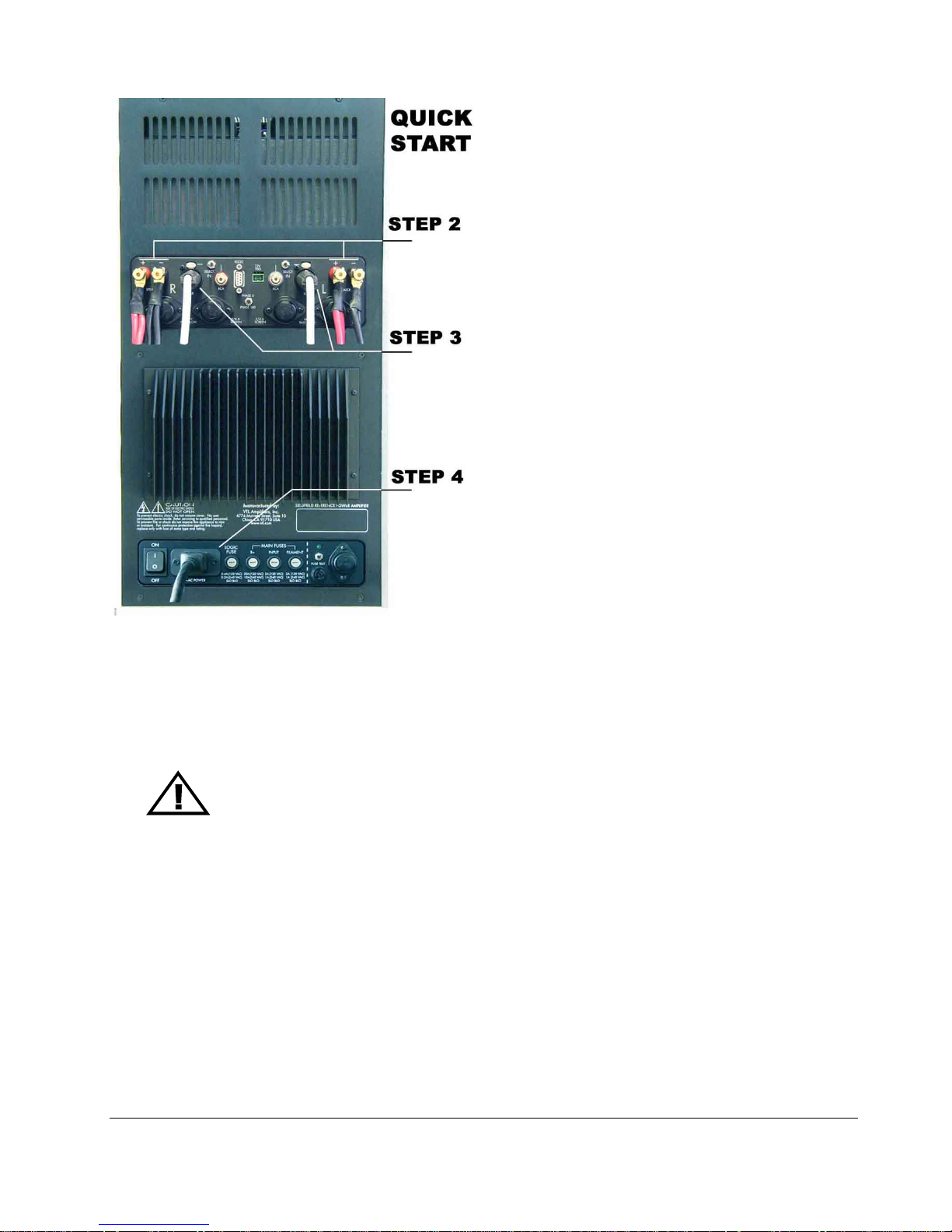
Step 2: Connect the Amplifiers to the Loudspeakers
Connect the loudspeaker cable from each speaker to the rear 5-way speaker binding post on the corresponding
amplifier. Use a 7/16” wrench to tighten the binding post nut, taking care not to over-tighten the binding post. Check
to make sure that the connections from the speakers to the amplifier’s binding post are correct: + (or red) to + and (or black) to –
Warning: The S-400 Series II Amplifier is a fully balanced design with a balanced output.
Care should be taken so that neither output is ever grounded.
Warning: Do not connect a sub-woofer to the output of the amplifier unless you are sure
that the subwoofer input is fully balanced and that neither phase can become
grounded.
Please consult your authorized VTL dealer or the VTL factory customer support department if you have any
questions on the fully balanced connection of the amplifier.
Step 3: Connect the Preamplifier to the Amplifier
Make sure all units are turned OFF, connect the preamplifier’s output to the amplifier’s input, matching the left and
right channels. If your preamplifier supports balanced output and you have balanced interconnects, connect the
preamplifier’s balanced output to the power amplifier’s balanced input, with the right channel output from the
preamplifier going to the input of the right amplifier, and similarly the left channel output of the preamplifier to the
input of the left amplifier.
S-400 Amplifier Owner’s Manual
VTL
12

If you are connecting to the power amplifier using single-ended interconnects, connect the preamplifier’s RCA/singleended channel output to the amplifier’s single-ended input, making sure the left channel of the preamplifier is
connected to the left amplifier, and so on.
Step 4: Connect the amplifier to the AC outlet
Before connecting to the AC, make sure that the Power rocker switch on the back of the amplifier is turned OFF.
Locate the 20A IEC power cord included with this unit, and connect the square end of the power cord to the AC
Power inlet located in the back of the amplifier (near the bottom) and the other end of the power cord to the AC outlet
on the wall. The plug should seat all the way into the connector, as loose connections can cause intermittent operation.
Step 5: Select the correct input
Set the Input Select switch on the back of the amplifier to either XLR or RCA, according to the type of interconnect
cable being connected, as shown above.
Warning: It is critical for proper sonic and noise level performance of this component that it be
properly configured for the correct mode of operation. If a balanced signal is applied to the inputs
the unit
Step 6. Power on the Preamplifier and source(s)
must be configured for XLR/balanced operation, and vice-versa.
Power on the preamplifier. Make sure that your preamplifier is either in the mute state or turn its volume to the zero position.
Before turning on the System, make certain that all connections are made firmly, with the
correct channels connected and phase settings, and that all switches are in the correct
position.
Step 7. Turn on the Amplifier
Locate the Power rocker switch at the back of the Amplifier on the bottom right hand corner next to the AC power
inlet. Turn the switch up to the “ON” position. For the first 10 seconds, you should see four dots scrolling on the
display window indicating that the amplifier is checking its internal status and when it is ready to go into the standby
mode, four blue bars“----“ will be displayed in the amplifier‘s numeric Display window, indicating that the amplifier is
now in standby mode ready for the power on command.
Locate the red POWER button on the front panel located beneath the display window in the center of the Amplifier.
Push and release the POWER button once to turn on the amplifier. The blue light above the red POWER button will
start to blink, and the display window indicates the power on countdown sequence, starting from 240.
During the power up countdown period, the amplifier is in MUTEd mode and has no output, as indicated by the red
MUTE light. The amplifier goes through its internal warm-up stage and the output tubes are automatically biased
during this period, until all tubes reach their optimum bias value.
At the end of the power-on countdown period, the POWER light changes to a steady blue and the MUTE light is
turned off, indicating that the unit is now ready to receive signal.
The Mode LED is steady green if the amplifier is in Tetrode mode (red if in triode mode). The default Mode setting is
green for Tetrode mode.
If optimum bias values are not reached by countdown 000 then the mute led will start to blink, and the 000 will stay on
the display until proper bias values are reached, after which time both the 000 display and the MUTE light will be
turned off, indicating that the amplifier is ready to receive signal.
S-400 Amplifier Owner’s Manual
VTL
13

Check that modes are the same on all channels, and that all channels are in phase (ie both showing the
INVERT indication on the front panel, or both not showing the INVERT indication, depending upon the
preamplifier used.)
Congratulations! You have just completed the Quick Start section for your new amplifier’s
operation. You may now wish to read the rest of this manual while relaxing and listening to some of
your favorite music.
S-400 Amplifier Owner’s Manual
VTL
14
CHAPTER 3
Operating the Amplifier
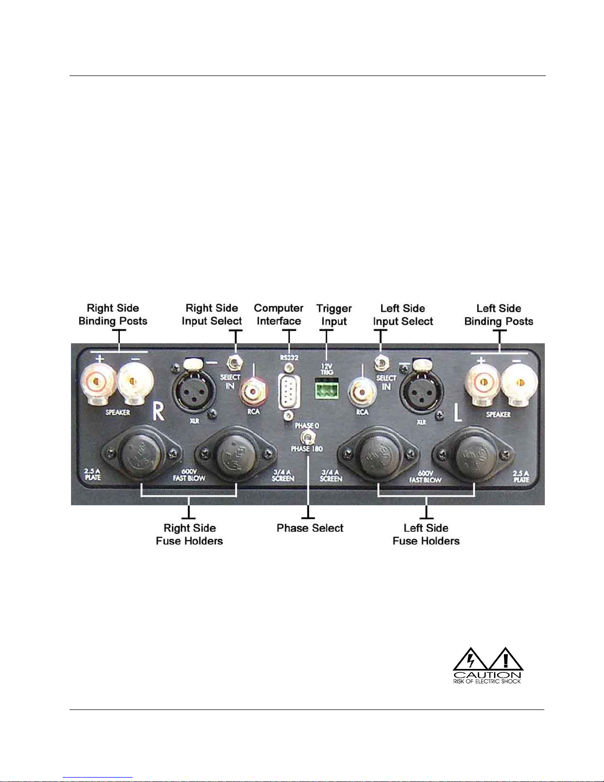
Rear panel controls and connections
There are two main panel areas on the back panel of the amplifier chassis:
• The top rear panel is the Input/Output interface panel and also contains the DC rail fuses.
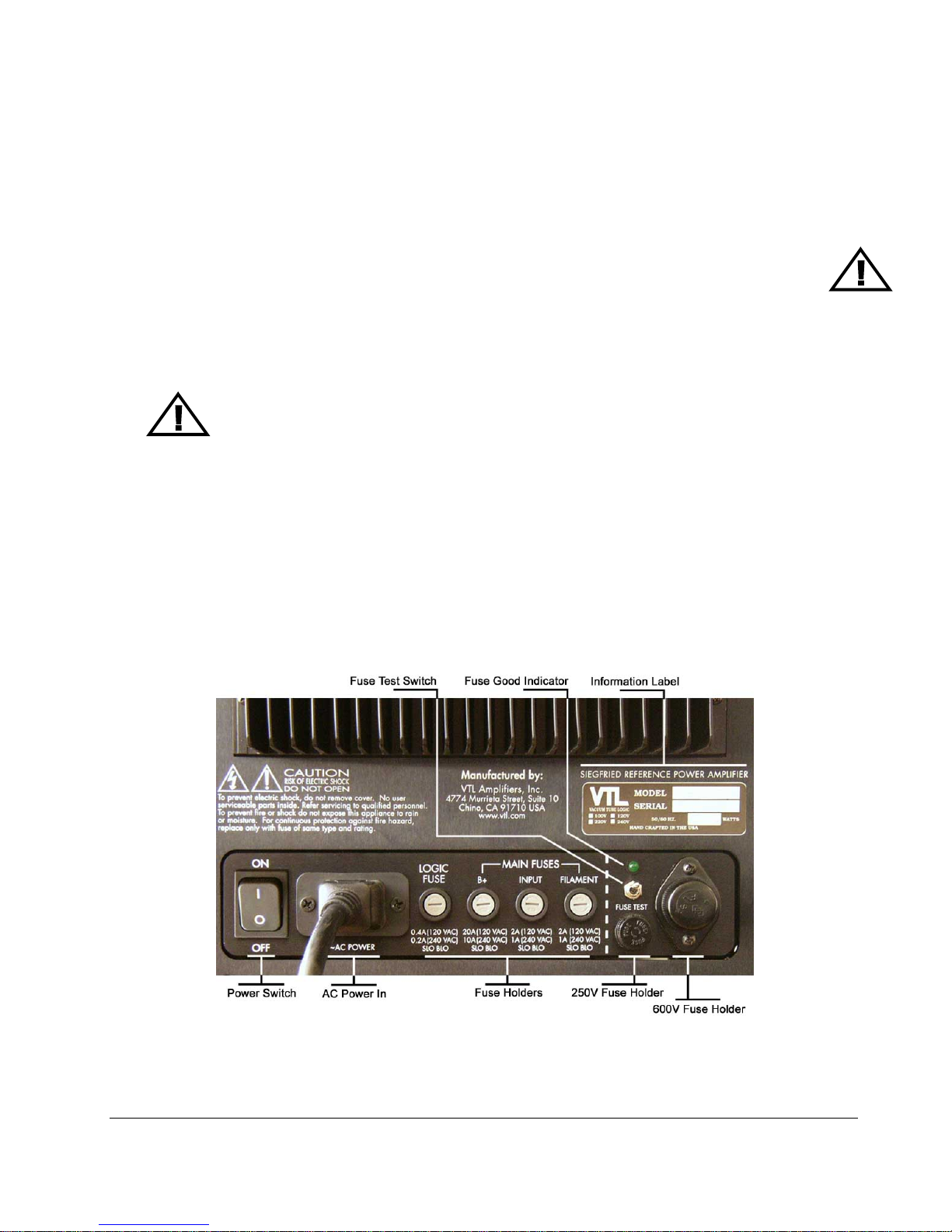
• The bottom rear panel is the Fuse/AC panel and houses the AC Power inlet, input fuses and the fuse
tester.
The Input/Output Interface Panel contains the following:
The Screen Fuse is the output tube’s screen fuse.
The Plate Fuse is the output tube’s plate fuse.
CAUTION: High voltages present. For continued protection against risk of fire
replace only with fuses of same type and rating.
The IR Receiver is used for receiving infrared signals from an external remote extender or central remote system.
S-400 Amplifier Owner’s Manual
VTL
Input/Output Interface Panel
15
The Balanced XLR input jack is for receiving a balanced signal from the source/preamplifier.
The Input Select switch is used to select the correct input. Move the handle towards the input to be selected.
The Phase select switch is used to select the input signal phase. Switch up for Phase 0 (Normal) and down for Phase
180 (INVERTed).
The single ended RCA input jack is for receiving a single ended signal from the source/preamplifier.
CAUTION: For best performance do not connect both single ended and balanced cables at the
same time.
The Trigger Input accepts an electrical signal command from an external component to remotely power up
or power down the amplifier. (6V to 24V, AC or DC)
The Speaker Binding Post is used to connect a loudspeaker to the amplifier. (Please note the correct phase when
connecting to the loudspeaker: Red (or +) to +, and Black (or -) to -.
Warning: The S-400 Series II amplifier is a fully balanced design with a balanced output.
Care should be taken so that neither output is ever grounded.
Warning: Do not connect a sub-woofer to the output of the amplifier unless you are sure
that the subwoofer input is fully balanced and that neither phase can become
grounded.
Please consult your authorized VTL dealer or the VTL factory customer support department if you have any
questions on the fully balanced connection of the amplifier.
The RS232 connector allows a bi-directional connection between the amplifier and a computer or central remote
system via a standard Male to Female DB9 RS232 cable, and will accept remote commands from the computer
and communicate operating status and diagnostic information back to the computer.
The Fuse/AC Panel contains the following:
S-400 Amplifier Owner’s Manual
VTL
Fuse/AC Rear Panel
16
 Loading...