

VTL MB-450 Series III, S-200 Owner's Manual

VTL
MB-450 Series III Signature Monoblock Amplifier
O w n e r ’ s M a n u a l

MAKING TUBES USER FRIENDLY
VTL MB-450 Signature Monoblock Amplifier
Information in this document is subject to change without notice. No part of this document may be reproduced
or transmitted in any form or by any means, electronic or mechanical, for any purpose, without the express
written permission by VTL.
Version History:
Version 1.0 September 30, 2010
Part Number: OM-MB-450 III
Copyright © 2010 by VTL Amplifiers Inc. All rights reserved.
4774 Murrieta Street, Suite 10
Chino, CA 91710, USA
Phone 909.627.5944 • Fax 909.627.6988
Email: mail@vtl.com • http://www.vtl.com
MB-450 Series III Signature Monoblock Owner’s Manual
i

TABLE OF CONTENT
CHAPTER 1 ......................................................................................................................................................................... 1
INTRODUCTION.............................................................................................................................................................. 1
The Origin of the MB-450 Signature Monoblock Amplifier ......................................................................................................... 1
Circuit overview:..........................................................................................................................................................................2
Symbol Conventions used in this guide......................................................................................................................................... 3
Electrical Safety Notice................................................................................................................................................................ 3
Water and Moisture......................................................................................................................................................................3
Location and Ventilation .............................................................................................................................................................. 3
Servicing....................................................................................................................................................................................... 4
Operational Warnings.................................................................................................................................................................. 4
CHAPTER 2 ......................................................................................................................................................................... 6
GETTING STARTED........................................................................................................................................................ 6
Before starting.............................................................................................................................................................................. 6
Replacing tubes............................................................................................................................................................................. 6
Connecting Your Amplifier to your system................................................................................................................................... 9
Voltage Setting............................................................................................................................................................................ 10
Power Source for your Amplifier................................................................................................................................................ 10
CHAPTER 3 ....................................................................................................................................................................... 11
OPERATING THE AMPLIFIER ........................................................................................................................................ 11
Turn On to Standby Mode........................................................................................................................................................... 11
From Standby Mode to Power On Mode.................................................................................................................................... 12
Mute and Unmute ....................................................................................................................................................................... 13
Tetrode /Triode Switching .......................................................................................................................................................... 14
Deck and Deck LED Indications ................................................................................................................................................ 15
Power off the amplifier into Standby mode................................................................................................................................. 17
Power off the amplifier at the rocker switch............................................................................................................................... 17
Using the DF switches................................................................................................................................................................ 17
DF Switch Settings..................................................................................................................................................................................18
Fault indication .......................................................................................................................................................................... 20
Tube Fault .............................................................................................................................................................................................................20
1. Tube red Fault - Mute LED blinking Red, deck LED green.................................................................................................20
2. High Current TUBE Fault -- Mute/Power/Mode LEDs off, deck LED green...............................................................21
3. TUBE green Fault -- Mute LED blinking green, deck LED green.....................................................................................21
Power Fault -- Mute LED blinking fast red, no deck LED lit..............................................................................................................................23
Replacing tubes........................................................................................................................................................................... 23
Resetting a Tube Red Fault......................................................................................................................................................... 26
Reset High Current Tube Fault .................................................................................................................................................. 27
Clearing a green tube Fault ....................................................................................................................................................... 27
Trigger functions ........................................................................................................................................................................ 27
Power On Trigger..................................................................................................................................................................................................27
Using a 12V trigger to power the amplifier on or off.......................................................................................................................................27
Mute Trigger .........................................................................................................................................................................................................28
Mode Trigger.........................................................................................................................................................................................................28
CHAPTER 4 ........................................................................................................................................................................ 29
CARE AND MAINTENANCE OF YOUR VTL AMPLIFIER................................................................................................. 29
Break In Period .......................................................................................................................................................................... 29
Power-on Period......................................................................................................................................................................... 29
Tube Types.................................................................................................................................................................................. 29
Tube Life..................................................................................................................................................................................... 29
Changing the Screen, Plate, Mains, Logic, B+ Input Fuses....................................................................................................... 30
Cleaning ..................................................................................................................................................................................... 31
Transporting MB-450................................................................................................................................................................. 31
Troubleshooting............................................................................................................................... ........................................... 32
MB-450 Series III Signature Monoblock Owner’s Manual
ii

SPECIFICATIONS .......................................................................................................................................................... 33
CHAPTER 5 ....................................................................................................................................................................... 34
WARRANTY................................................................................................................................................................. 34
APPENDIX......................................................................................................................................................................... 35
Warranty Registration................................................................................................................................................................ 35
Service Notes.............................................................................................................................................................................. 35
MB-450 Series III Signature Monoblock Owner’s Manual
iii

CHAPTER 1
Introduction
Congratulations on your purchase of the VTL MB-450 Signature Monoblock Amplifier – an
advanced- technology vacuum tube amplifier engineered for outstanding sonic performance.
VTL is delighted to welcome you as a new owner of our MB-450 Series III Signature monoblock power amplifier. This
precision-engineered high-performance amplifier will provide you with many years of trouble-free listening pleasure.
This newest iteration of the long-standing MB-450 platform is a full re-working of the complete amplifier, with a fully
balanced input stage driving a differential phase splitter and a push-pull output stage with an improved, balanced output
transformer, all combining to bring the sonic performance of the venerable 450 platform to even greater heights. The
Series III also incorporates VTL’s advanced Auto Bias and Fault Sensing technology--features formerly available only
with our flagship Reference products. A revised power supply and improved electronics give the MB-450’s an ultra-fast
transient response and a dynamic range that discerning music and film lovers will instantly notice and appreciate. We
thank you for selecting this amplifier for your home audio/theater system, and trust that you will enjoy its musical
distinction for years to come.
To get the most benefit from your purchase, we recommend that you take time to familiarize yourself with the
features of this product. Please take a few minutes to read through this owner’s manual, as it contains all of the
installation procedures needed to connect your new amplifier to the rest of your system, and details the many
functions that it can perform. After you have finished reading this manual, please put it in a safe place for future
reference.
The Origin of the MB-450 Signature Monoblock Amplifier
The MB-450 Signature Monoblock Amplifier (including its predecessors) has been a core model in the VTL line
for over 20 years. With the release of the Deluxe 300 monoblocks in the late 80’s, VTL successfully introduced a
high power amplifier that could drive a wide range of speakers and yield outstanding performance for a
reasonable price. The model evolved incrementally over the years, including a name change to the MB-450
Signature Monoblocks in 1996.
With the release of the MB-450 Series II Signature Monoblocks in 2007, the Smart Tube Technology first
introduced in the flagship Siegfried Reference monoblocks in 2004 became an essential standard feature in the
VTL Signature monoblock family. This system encompasses logic-controlled automatic biasing--which
continually checks each tube for optimal performance--and an array of fault-sensing diagnostics that alert users
to the operating status of each tube. The "smart tube" technology puts an end to the guesswork formerly
inherent in large tube amplifiers, making the new MB-450s easier to use and maintain. Other technology that has
trickled down from the Siegfried amplifier includes a precision-regulated power supply and upgraded circuitry
components.
The MB-450 Series III Signature Monoblock incorporates even greater technological improvements with the
goal of enhancing the amplifier’s ability to drive a diverse range of speaker types. These include a re-designed
fully balanced differential input stage driving a differential phase splitter and a lower impedance push-pull output
stage with a dramatically improved, fully balanced, interleaved and coupled output transformer. As a result, the
MB-450 has attained new thresholds of sonic performance, with greatly improved bass tightness and dynamics.
MB-450 Series III Signature Monoblock Owner’s Manual
1

Compared to former versions of the MB-450, the Series III offers an unrestrained sense of openness, tighter and
more controlled bass, and an ease and musical neutrality that give you the most satisfying listening experience.
Circuit overview:
An all-tube amplifier, the MB-450 Series III is the culmination of VTL’s most advanced thinking in performance
engineering. A proprietary regulated power supply, high-grade parts, and an automatic tube bias system ensure
ultra high fidelity audio reproduction, while tube fault diagnostics and user feedback offer the ultimate in
usability and convenience.
The audio amplifier is comprised of a fully balanced differential input stage driving a differential phase splitter
and a lower impedance push-pull output stage with a dramatically improved, fully balanced, interleaved and
coupled output transformer. Furthermore, the new design in the Series III amplifier incorporates a shorter, faster
and fully balanced negative feedback loop, with zero global negative feedback. The revised negative feedback
loop completely eliminates ringing and requires no capacitor compensation to maintain critical phase integrity
and information.
Further engineering innovations for the MB450 Series III include a variable Damping Factor feedback control
that allows the user to precisely adjust the amplifier’s output impedance by setting the amount of negative
feedback to one of four possible levels. Impedance can now be varied to suit the listener’s taste, and to improve
control of the loudspeaker loads to deliver best performance.
Adjustable precision-regulated bias and screen supplies keep the operating point of the output tubes constant even
under AC and main power supply fluctuations, and stabilize the power supplies for greater tonal stability and sonic
integrity especially during complex, dynamic signal conditions.
All critical voltages in the power supply are precision regulated for consistent and predictable performance under
a wide variety of conditions. Large energy storage reservoirs mean that the amplifier is capable of delivering huge
peak current swings into demanding loads for powerful musical performance.
Optimized operating voltages and timed current inrush limiting dramatically extend tube life, with low idle
current draw on all stages. An ever-warm position further lowers idle current while keeping all voltages present
so the circuit remains warm when not in use.
The amplifier can run in one of two operating modes: Tetrode or Triode. The user can change mode either in
standby or in power-on mode. Users often prefer one mode to another, depending on the type of music. For
example, tetrode may offer a wider sound stage and greater dynamics for complex and demanding symphonic
music, while triode may work better for small ensembles or solo instruments.
Comprehensive fault sensing monitors the status of the output tubes, and alerts the user to any adverse
conditions. In the case of a problem in any of the output tubes, the amplifier will immediately shut down. The
tube fault is indicated on the front panel, as well as by a blinking LED on the top deck next to the faulty tube
making diagnosis and tube replacement easy.
The logic-controlled automatic bias system is designed to keep the tubes at peak performance and operates
completely outside of the signal path. The tube biasing circuit checks and adjusts the tube bias values
automatically during the power-on sequence, as well as when the amplifier is at idle (i.e. when no music signal is
being amplified.), and drops out of the circuit path when music signal is detected.
MB-450 Series III Signature Monoblock Owner’s Manual
2
Symbol Conv entions used in this guide
Certain symbols are used in this owner’s manual to draw your attention to important points being discussed. For your
own safety and that of your equipment you should note and heed the warnings that follow these
symbols.
The “Warning - Pay Particular Attention” symbol used is:
And the “Warning – Observe These Precautions for Your Safety” is:
Electrical Safety Notice
Electrical voltage from power cables can be hazardous. We recommend that the power cord
used with this unit be connected to a properly grounded (three-prong) AC outlet. There are
also hazardous voltages present inside the unit. To prevent electrical shock, avoid removing
the cover of this amplifier, and under no circumstances remove it while the unit is powered
on.
Warning – Under no circumstances should any attempt be made to
circumvent the ground system to the AC line for any reason
ground lifted system can be potentially extremely dangerous, both to persons that might
come in contact with the unit, and to the unit itself, and proper RF shielding cannot be
attained without a secure ground connection.
. Using a
Damage to the unit that is the result of improper AC connection and grounding will not be covered under the
warranty.
Prior to connecting this amplifier to any audio or video equipment in your system, make sure this
unit’s power (and the rest of the equipment connected to its input and output channels) is turned
off. Adding or removing input or output cables to the amplifier while the system is powered on can
cause damage to the amplifier and possibly also to the rest of the system.
Water and Moisture
The amplifier should be kept away from sources of water or moisture. If liquid enters the unit
it must be immediately returned to your dealer for servicing. Under no circumstances should
you try to power the unit on - the hazardous voltages present in this unit, when combined
with liquid, can result in serious injury upon even the slightest contact.
Location and V entilation
Warning – To avoid risk of failure due to overheating, do not stack chassis
components
The amplifier emits heat and needs proper ventilation to ensure long operational life.
Ensure that the amplifier is installed in a location that is stable and well ventilated. If the amplifier is
placed in a built-in installation, ensure that there is adequate room for air to flow through the
MB-450 Series III Signature Monoblock Owner’s Manual
3
ventilation openings. Allow at least 12 inches clearance on the top and around the sides of the chassis of the amplifier.
The warranty does not cover units that are damaged due to overheating from incorrect installation.
Tiptoes or other isolation accessories may prove useful in reducing mechanical vibrations or other external vibrations
that might affect sonic performance, and we have found that such accessories can offer distinct sonic improvements
when used correctly. In all cases you should be sure to install this amplifier in a location that is stable.
The warranty does not cover damage due to the unit falling.
Do not place the amplifier next to heat sources such as radiators, stoves or other appliances.
Do not place the amplifier where small children might be able to tamper with the equipment. If it is not possible to
place the amplifier out of the reach of small children it is recommended that you remove power cables when the
equipment is not in use.
Servicing
Do not attempt to service the amplifier beyond the procedures described in this manual. For all
other service and questions, please contact your authorized VTL dealer or the factory.
Operational Warnings
It is critical for proper sonic performance of this component that it be properly configured for
the mode of operation while playing. If a balanced signal is applied to the inputs the amplifier
must be configured for balanced operation, and vice-versa.
Always make all connections before powering the amplifier on. Ensure that interconnect
cables are firmly seated and that there is no visible damage to the cables.
Connecting or disconnecting the amplifier while powered on can damage the output stage. Such
damage will not be covered under the warranty.
Warning: The MB-450 Series III is a fully balanced design with a balanced output. Care
should be taken so that neither output is ever grounded.
Warning: Do not connect a sub-woofer to the output of the amplifier unless you are sure
that the subwoofer input is fully balanced and that neither phase can become
grounded.
Please consult your authorized VTL dealer or the VTL factory customer support department if you have any questions
on the fully balanced connection of the amplifier.
MB-450 Series III Signature Monoblock Owner’s Manual
4

Do not attempt to disassemble the amplifier chassis or remove any covers from
the amplifier. Always consult with your VTL authorized dealer or the VTL factory support
department before attempting any service work on any VTL unit.
Do not touch the tubes after the amplifier is turned on. Tubes can get very hot while
the amplifier is operating. Turn off the amplifier and allow the tubes to cool down before
attempting to work with the tubes.
Tube components can be heavy and awkward to lift, with the weight unevenly distributed. You
should not attempt to move the unit without help. The amplifier weighs approximately 120 lbs.
(55 Kg).
Use only the same type and rating of fuses as specified in the owners’ manual and marked on the
unit.
Using fuses that exceed the ratings or attempting to bypass any fuses can cause an extremely
hazardous condition and will void the warranty.
MB-450 Series III Signature Monoblock Owner’s Manual
5

CHAPTER 2
Getting Started
Before starting
The MB-450 Signature Monoblocks are shipped in cartons and wrapped in thick plastic. The plastic is not strong enough to
support the unit, and may tear if you try to lift the unit out of the box with it. Also there are protruding switches which could
break if the unit is not properly handled, and in addition to the awkward, unbalanced heavy load
the unit has a cleaning polish on it which makes it slippery and hard to grasp. We have found that
the best way to remove the amplifier from the box is as follows:
1. With the box on a thick carpeted floor, fold back all the flaps of the top of the carton, leaving all the packing
foam in place. Remove all power cords, Owner’s Manual packages etc. from the carton and save these for
future use. Roll the carton onto one long side on top of the flap.
2. Roll the box once more onto the open top and, making sure that none of the flaps is trapped under the carton,
lift the carton off the unit.
3. Lift the top foam away from the upside down unit and carefully cut away the plastic from around the amplifier.
4. Lift the amplifier up and away from the packaging so that it lands on its four rubber feet. Then lift away the
packaging and set all the packaging in the carton.
5. When lifting the unit be sure to only lift it from the bottom under the transformers. Be careful not to break any
switches. Be sure to only set the amplifier down on its bottom side on the four rubber feet on a stable surface.
Setting it on any other side may damage protruding components.
If the unit is too heavy or too awkward to lift then do not attempt to do this by yourself, but rather find someone to
help you. Save the carton and all packaging for any future shipment of the amplifiers.
Warning: This unit is extremely heavy, and weighs over 100 lbs. Unpacking should be done by two or
more people who are capable of lifting a heavy load. Ensure that the amplifier would not fall and injure
someone. Do not attempt to lift the unit yourself.
Check to make sure that no physical damage has occurred during shipping of the unit. There should be no
rattles inside the amplifier chassis. Look through the top cover and check to see that the tubes appear
properly seated in their sockets, and that no tubes are white on top. Contact your VTL dealer immediately
if any physical damage is detected.
Replacing tubes
Turn off the rear rocker switch and remove the power cable before removing any
covers from the amplifier.
Follow the steps below to remove the cage of the amplifier:
MB-450 Series III Signature Monoblock Owner’s Manual
6
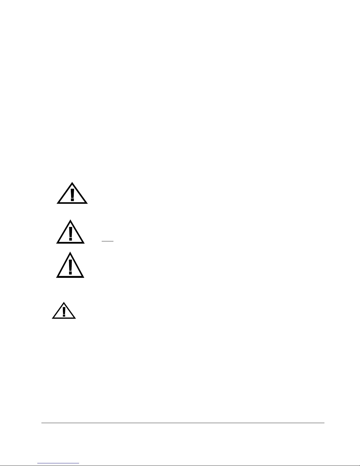
1. Locate the left and right covers on the cage. With a #2 Phillips screw driver, remove the four flat
head screws on the top side of the two covers.
2. Locate the two screws on the side of the left and right covers. Remove these two screws with the #2
Phillips screw driver also.
3. Save these screws in a safe place so that they can be re-used to fasten the cage back to the amplifier.
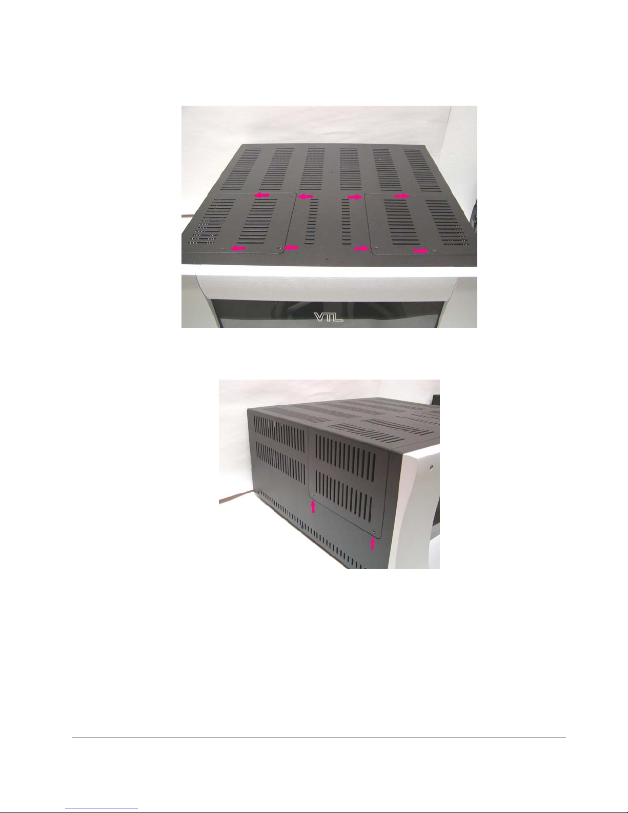
4. Remove the left and right covers of the cage and locate the tube sockets for the output tubes on the deck of
the amplifier. For the MB-450 amplifier, there should be a total of 8 sockets for the output tubes, 4 on the left
side and 4 on the right side of the cage covers.
5. Insert the output tubes into each of the output tube sockets from tube # 1 to # 4 on the left side of the cover
and 5 to 8 on the right side of the cover.
MB-450 Series III Signature Monoblock Owner’s Manual
7
.
Hold onto the upper portion of the tube towards its tip. Lower the tube onto the socket, making sure that the
pins from the tube matches the holes in the socket. There are either two pins on the tube which are spaced at a
wider distance from each other than the rest of the pins (9 pin miniature tubes), or there is a locating keyway in
the middle of the tube (8 pin octal tubes). Make sure that these locators go into the side of the socket which
matches. Press the tube firmly into its socket, using a gentle force and a slight “rocking” motion. When the
tube is properly and completely inserted into the socket it should be firmly implanted and does not give in to
any movement at all when you try to rock it.
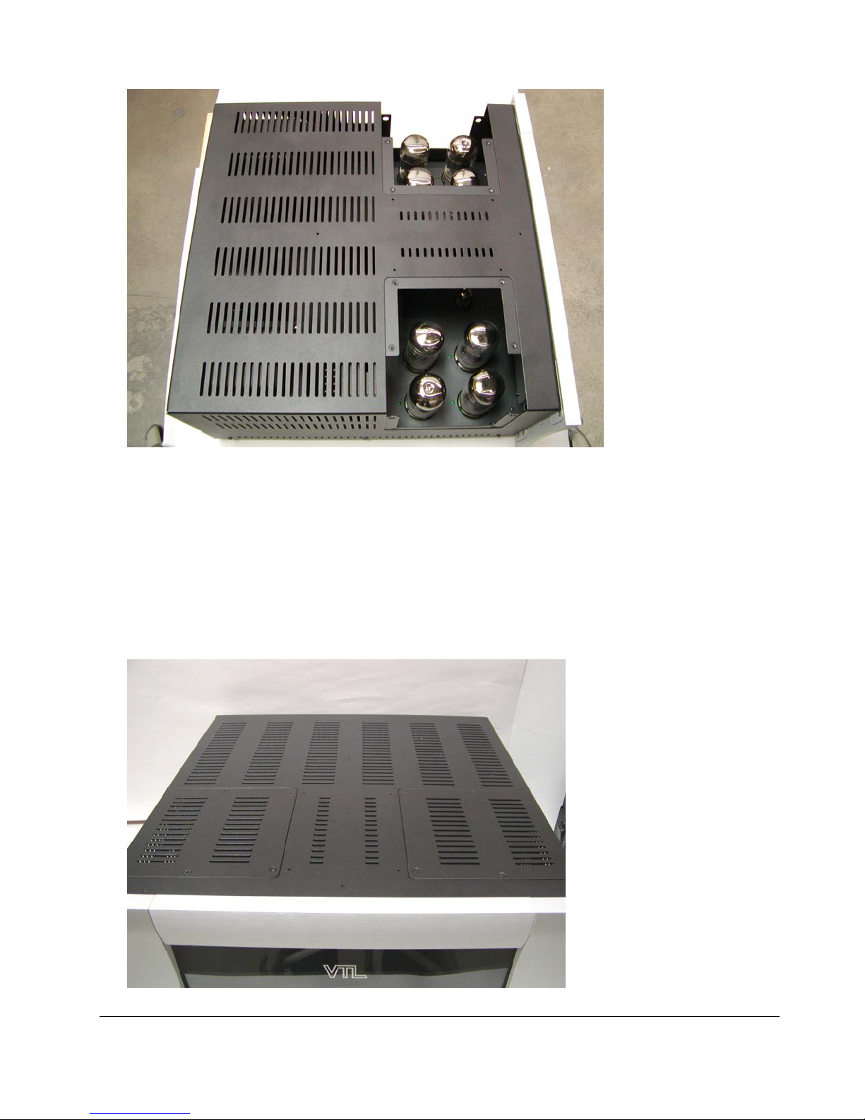
5. After the output tubes are firmly located in their sockets, restore the left and right top covers back onto
the cage. Fit the original screws onto cover and use the #2 Phillips screw driver to tighten the screws.
Do not overtighten and make sure the screws are in securely.
Notes for the servicing technician:
MB-450 Series III Signature Monoblock Owner’s Manual
8
 Loading...