

Page 1

EX1000A/EX1000A-TC
48-CHANNEL PRECISION VOLTAGE MEASUREMENT INSTRUMENT
EX1016A
32-CHANNEL PRECISION VOLTAGE MEASUREMENT,
16-CHANNEL PRECISION THERMOCOUPLE INSTRUMENT
EX1032A
16-CHANNEL PRECISION VOLTAGE MEASUREMENT,
32-CHANNEL PRECISION THERMOCOUPLE INSTRUMENT
EX1048A
48-CHANNEL PRECISION THERMOCOUPLE INSTRUMENT
EX10SC
16-CHANNEL SIGNAL CONDITIONING EXPANSION CHASSIS
EX1000A-51C
51-CHANNEL PRECISION VOLTAGE MEASUREMENT
RX1032
32-CHANNEL PRECISION RUGGED THERMOCOUPLE INSTRUMENT
EX1044
2-CHANNEL PRECISION VOLTAGE ISOLATED MEASUREMENT
2-CHANNEL PRECISION CURRENT ISOLATED MEASUREMENT
44-CHANNEL PRECISION THERMOCOUPLE INSTRUMENT
USER’S MANUAL
P/N: 82-0122-000
November 29th, 2016
VTI Instruments Corp.
2031 Main Street Irvine,
CA 92614-6509, (949) 955-1894
Page 2

VTI Instruments Corp.
2 EX10xxA Preface
TABLE OF CONTENTS
INTRODUCTION
Certification .......................................................................................................................................................... 9
Warranty ............................................................................................................................................................... 9
Limitation of Warranty ......................................................................................................................................... 9
Restricted Rights Legend ...................................................................................................................................... 9
DECLARATION OF CONFORMITY ............................................................................................................................. 10
DECLARATION OF CONFORMITY ............................................................................................................................. 11
GENERAL SAFETY INSTRUCTIONS ........................................................................................................................... 12
Terms and Symbols ............................................................................................................................................ 12
Warnings ............................................................................................................................................................. 12
SUPPORT RESOURCES ............................................................................................................................................. 14
SECTION 1 .................................................................................................................................................................. 15
INTRODUCTION ................................................................................................................................ ....................... 15
Overview ............................................................................................................................................................ 15
Features ............................................................................................................................................................... 16
Combined Thermocouple and Analog Inputs ................................................................................................ 16
End-to-end Self-calibration ........................................................................................................................... 16
Scalable for Synchronized High-Speed, High-Channel Count ...................................................................... 16
Open Thermocouple Detection (OTD) .......................................................................................................... 16
Cold Junction Compensation (CJC) .............................................................................................................. 17
Simplified Installation, Setup and Control .................................................................................................... 17
Channel Independence .................................................................................................................................. 17
Measurement Range ...................................................................................................................................... 17
Hardware Filter ............................................................................................................................................. 18
Input Connectors ........................................................................................................................................... 18
Sampling Rate ............................................................................................................................................... 18
Digital I/O and Limits ................................................................................................................................... 18
LXI Trigger Bus ............................................................................................................................................ 19
Triggering ...................................................................................................................................................... 19
EX10xxA Specifications .................................................................................................................................... 19
EX10xxA Dimensional Diagram ........................................................................................................................ 24
RX1032 Diagram ................................................................................................................................................ 26
EX1044 Diagram ................................................................................................................................................ 28
Explanation of Specifications ............................................................................................................................. 30
Maximizing Measurement Performance ............................................................................................................. 31
Utilize self-calibration ................................................................................................................................... 31
Dynamic Calibration in RX1032 ................................................................................................................... 31
Utilize self-test .............................................................................................................................................. 31
Allow for cold junction thermal stabilization ................................................................................................ 31
Select the proper hardware filter ................................................................................................................... 33
Choose an appropriate sampling rate ............................................................................................................ 33
Select the proper location .............................................................................................................................. 33
Use the correct wiring ................................................................................................................................... 33
SECTION 2 .................................................................................................................................................................. 35
PREPARATION FOR USE ........................................................................................................................................... 35
Unpacking EX10xxA, EX1000A-51C ............................................................................................................... 35
Unpacking RX10xx ............................................................................................................................................ 35
Unpacking EX1044 ............................................................................................................................................ 35
Installation Location ................................ ................................................................................................ ........... 36
Installation Options ............................................................................................................................................. 36
Rackmount Installation Option of EX10xxA ................................................................................................ 36
Page 3

www.vtiinstruments.com
EX10xxA Preface 3
Rack Ear Installation Option ......................................................................................................................... 38
Tabletop Installation Option .......................................................................................................................... 39
Installation Option of RX10xx ...................................................................................................................... 40
Software Installation ........................................................................................................................................... 43
LInC-U Installation ....................................................................................................................................... 44
Network Configuration ....................................................................................................................................... 44
Reset button for EX10xxA/EX10xxA-51C ................................................................................................... 45
Network Troubleshooting ................................................................................................................................... 45
Restore the EX10xxA’s Default Network Settings ....................................................................................... 45
Determine PCs Network Settings .................................................................................................................. 45
Set the EX10xxA to Auto IP ......................................................................................................................... 47
Set the EX10xxA to Static IP ........................................................................................................................ 47
Restore the Host PCs Network Settings ........................................................................................................ 48
Using Multiple Network Cards ..................................................................................................................... 48
Time Configuration ............................................................................................................................................ 50
Input Connections / Wiring ................................................................................................................................ 50
Thermocouple Connections ........................................................................................................................... 50
Voltage Connections ..................................................................................................................................... 52
RX10xx Connections .................................................................................................................................... 54
SECTION 3 .................................................................................................................................................................. 57
BASIC OPERATION ................................ ................................................................ ................................ .................. 57
Introduction ........................................................................................................................................................ 57
Engineering Unit (EU) Conversion .................................................................................................................... 57
Linear Correction .......................................................................................................................................... 58
Voltage Measurement Ranges ............................................................................................................................ 58
Hardware Filter ................................................................................................................................................... 58
Measurement Range / Input Protection............................................................................................................... 58
Cold Junction Compensation (CJC) ................................................................................................................... 59
Temperature Units .............................................................................................................................................. 60
Sampling Rate / Noise Performance ................................................................................................................... 60
Scan List Configuration ...................................................................................................................................... 61
Scan List Timing ................................................................................................................................................ 61
Self-calibration ................................................................................................................................................... 62
Dynamic Calibration in RX1032 ........................................................................................................................ 63
Open Transducer Detection / Limits ................................................................................................................... 63
Digital I/O and DIO Limit Events ...................................................................................................................... 63
LXI Trigger Bus ................................................................................................................................................. 65
Locking ............................................................................................................................................................... 67
Triggering ........................................................................................................................................................... 67
Data Format ........................................................................................................................................................ 67
Acquiring Data ................................................................................................................................................... 67
Retrieving Data ................................................................................................................................................... 68
User-defined Conversions .................................................................................................................................. 69
SECTION 4 .................................................................................................................................................................. 70
TRIGGERING ....................................................................................................................................................... 70
Overview ............................................................................................................................................................ 70
Events ................................................................................................................................................................. 71
Maximizing Measurement Performance ............................................................................................................. 72
Maximum Trigger Rate ...................................................................................................................................... 73
SECTION 5 .................................................................................................................................................................. 75
WEB PAGE OPERATION ........................................................................................................................................... 75
Introduction ........................................................................................................................................................ 75
General Web Page Operation ............................................................................................................................. 75
Trigger Menu ...................................................................................................................................................... 77
Configuration ................................................................................................................................................ 77
Initialize ......................................................................................................................................................... 78
Page 4

VTI Instruments Corp.
4 EX10xxA Preface
Abort ............................................................................................................................................................. 78
Software Arm ................................................................................................ ................................ ................ 78
Software Trigger ........................................................................................................................................... 78
LAN Events Menu .............................................................................................................................................. 78
Configuration ................................................................................................................................................ 78
Event Log ...................................................................................................................................................... 79
Status ............................................................................................................................................................. 80
Scan List Menu ................................................................................................................................................... 80
Configuration ................................................................................................................................................ 80
Filters............................................................................................................................................................. 81
Ranges ........................................................................................................................................................... 81
Data Menu .......................................................................................................................................................... 81
Get FIFO Count ............................................................................................................................................. 81
Retrieve Data ................................................................................................................................................. 81
Continuous Polling ........................................................................................................................................ 81
FIFO Configuration ....................................................................................................................................... 81
IO Menu .............................................................................................................................................................. 82
Digital IO ...................................................................................................................................................... 82
Trigger Bus .................................................................................................................................................... 82
Limits Menu ....................................................................................................................................................... 83
Limits ............................................................................................................................................................ 83
DIO Limit Events .......................................................................................................................................... 83
Device Menu....................................................................................................................................................... 85
Self-calibration .............................................................................................................................................. 85
Dynamic Calibration in RX1032 ................................................................................................................... 86
Get Calibration Files ..................................................................................................................................... 86
Network Configuration.................................................................................................................................. 87
Device Identify .............................................................................................................................................. 88
Time Configuration ................................................................................................................................ ....... 88
LXI Synchronization ..................................................................................................................................... 90
Reset Device .................................................................................................................................................. 91
Hard Reboot .................................................................................................................................................. 91
Upgrade Firmware ......................................................................................................................................... 91
Locking Menu..................................................................................................................................................... 92
Lock............................................................................................................................................................... 92
Unlock ........................................................................................................................................................... 92
Break Lock .................................................................................................................................................... 92
Advanced Menu .................................................................................................................................................. 92
User Conversions .......................................................................................................................................... 92
User CJC Temp ............................................................................................................................................. 92
Configuration Examples ..................................................................................................................................... 93
Example #1 .................................................................................................................................................... 93
Example #2 .................................................................................................................................................... 94
SECTION 6 .................................................................................................................................................................. 95
PROGRAMMING ....................................................................................................................................................... 95
Programming Sequence ...................................................................................................................................... 95
Default Settings .................................................................................................................................................. 96
EX10xxA Backward Compatibility .................................................................................................................... 97
General Commands / Queries ............................................................................................................................. 97
Initializing the device .................................................................................................................................... 97
Resetting the device ...................................................................................................................................... 98
Performing Self-Calibration .......................................................................................................................... 98
Dynamic Calibration in RX1032 ................................................................................................................... 99
Acquiring a Lock ........................................................................................................................................... 99
Configure the Scan List .................................................................................................................................... 100
Configure the EU Conversions ......................................................................................................................... 100
Configure the Range ......................................................................................................................................... 101
Page 5

www.vtiinstruments.com
EX10xxA Preface 5
Configure the Advanced Conversion Options .................................................................................................. 101
Employing an external cold junction ........................................................................................................... 101
Employing custom thermocouple conversions ............................................................................................ 101
Configure the Voltage Measurement Channels ................................................................................................ 102
Configure the Filter Frequencies ...................................................................................................................... 102
Configure the FIFO .......................................................................................................................................... 103
Configure the Limit System .............................................................................................................................. 103
Configure the Digital I/O System ..................................................................................................................... 104
Configure DIO Limit Events ....................................................................................................................... 106
Configure the Trigger Model ............................................................................................................................ 107
Configure the ARM event system ............................................................................................................... 107
Configure the TRIG event system ............................................................................................................... 109
Configure general trigger model parameters ............................................................................................... 110
Resetting the trigger model configuration ................................................................................................... 111
Initiate the Trigger Model ................................................................................................................................. 111
Configure the LXI Trigger Bus ........................................................................................................................ 111
Trigger Event .................................................................................................................................................... 113
Retrieving Data (Read FIFO and Streaming Data) ........................................................................................... 113
Read FIFO ................................................................................................................................................... 113
Asynchronous Streaming Data .................................................................................................................... 116
Example Program ............................................................................................................................................. 122
SECTION 7 ................................................................................................................................................................ 125
FUNCTION CALLS ................................................................................................................................................. 125
Introduction ...................................................................................................................................................... 125
Function Return Value ...................................................................................................................................... 125
Alphabetical Function Set ................................................................................................................................. 125
Sample Function Definition .............................................................................................................................. 129
Function_Name ........................................................................................................................................... 129
vtex10xxA_abort ......................................................................................................................................... 131
vtex10xxA_append_scanlist ........................................................................................................................ 132
vtex10xxA_break_lock ............................................................................................................................... 133
vtex10xxA_check_lock ............................................................................................................................... 134
vtex10xxA_clear_lan_eventlog ................................................................................................................... 135
vtex10xxA_close ......................................................................................................................................... 136
vtex10xxA_disable_streaming_data ............................................................................................................ 137
vtex10xxA_enable_streaming_data ............................................................................................................ 138
vtex10xxA_enable_streaming_dataEx ........................................................................................................ 140
vtex10xxA_error_message .......................................................................................................................... 142
vtex10xxA_error_query .............................................................................................................................. 143
vtex10xxA_get_accum_limit_status ........................................................................................................... 144
vtex10xxA_get_alarm ................................................................................................................................. 145
vtex10xxA_get_alarm_enable ..................................................................................................................... 146
vtex10xxA_get_arm_count ......................................................................................................................... 147
vtex10xxA_get_arm_delay ......................................................................................................................... 148
vtex10xxA_get_arm_infinite ....................................................................................................................... 149
vtex10xxA_get_arm_lan_eventID .............................................................................................................. 150
vtex10xxA_get_arm_lan_filter.................................................................................................................... 151
vtex10xxA_get_arm_source ........................................................................................................................ 152
vtex10xxA_get_arm_sourceEx ................................................................................................................... 153
vtex10xxA_get_calibration_file ................................................................ ................................ .................. 154
vtex10xxA_get_calibration_running ........................................................................................................... 155
vtex10xxA_get_channel_conversion .......................................................................................................... 156
vtex10xxA_get_channel_count ................................................................................................................... 157
vtex10xxA_get_channel_range ................................................................................................................... 158
vtex10xxA_get_channel_type ..................................................................................................................... 159
vtex10xxA_get_dio_input ................................................................ ........................................................... 160
vtex10xxA_get_dio_limit_event ................................................................................................................. 161
Page 6

VTI Instruments Corp.
6 EX10xxA Preface
vtex10xxA_get_dio_limit_event_invert ...................................................................................................... 162
vtex10xxA_get_dio_limit_event_latch ....................................................................................................... 163
vtex10xxA_get_dio_output ......................................................................................................................... 164
vtex10xxA_get_dio_output_enable ................................................................ ................................ ............. 165
vtex10xxA_get_fifo_config ........................................................................................................................ 166
vtex10xxA_get_fifo_count .......................................................................................................................... 167
vtex10xxA_get_filt_freq ............................................................................................................................. 168
vtex10xxA_get_init_cont ............................................................................................................................ 169
vtex10xxA_get_lan_event_domain ............................................................................................................. 170
vtex10xxA_get_lan_event_source_state ..................................................................................................... 171
vtex10xxA_get_lan_eventlog_count ........................................................................................................... 172
vtex10xxA_get_lan_eventlog_enabled ....................................................................................................... 173
vtex10xxA_get_lan_eventlog_overflowmode ............................................................................................. 174
vtex10xxA_get_limit_set0 .......................................................................................................................... 175
vtex10xxA_get_limit_set0_manual ................................................................ ................................ ............. 176
vtex10xxA_get_limit_set1 .......................................................................................................................... 177
vtex10xxA_get_linear_correction ............................................................................................................... 178
vtex10xxA_get_model ................................................................................................................................ 179
vtex10xxA_get_OTD_enable ...................................................................................................................... 180
vtex10xxA_get_ptp_info ............................................................................................................................. 181
vtex10xxA_get_scanlist .............................................................................................................................. 182
vtex10xxA_get_serialNumber ..................................................................................................................... 183
vtex10xxA_get_shield_gnd_config ................................................................ ................................ ............. 184
vtex10xxA_get_system_time ...................................................................................................................... 185
vtex10xxA_get_trig_lan_eventID ............................................................................................................... 186
vtex10xxA_get_trig_lan_filter .................................................................................................................... 187
vtex10xxA_get_trigger_count ..................................................................................................................... 188
vtex10xxA_get_trigger_delay ..................................................................................................................... 189
vtex10xxA_get_trigger_infinite .................................................................................................................. 190
vtex10xxA_get_trigger_source ................................................................................................................... 191
vtex10xxA_get_trigger_sourceEx ............................................................................................................... 192
vtex10xxA_get_trigger_timer ..................................................................................................................... 193
vtex10xxA_get_user_cjc_enable ................................................................................................................. 194
vtex10xxA_get_user_cjc_temp ................................................................................................................... 195
vtex10xxA_get_user_conversion ................................................................................................................ 196
vtex10xxA_get_vtb_input ................................................................ ........................................................... 197
vtex10xxA_get_vtb_output ......................................................................................................................... 198
vtex10xxA_get_vtb_output_enable ................................................................ ................................ ............. 199
vtex10xxA_get_vtb_wiredor ....................................................................................................................... 200
vtex10xxA_get_vtb_wiredor_bias .............................................................................................................. 201
vtex10xxA_init ............................................................................................................................................ 202
vtex10xxA_init_imm .................................................................................................................................. 203
vtex10xxA_lock .......................................................................................................................................... 204
vtex10xxA_pop_logged_LAN_event .......................................................................................................... 205
vtex10xxA_read_fifo................................................................................................................................... 206
vtex10xxA_read_fifoEx .............................................................................................................................. 207
vtex10xxA_reset .......................................................................................................................................... 208
vtex10xxA_reset_fifo .................................................................................................................................. 209
vtex10xxA_reset_trigger_arm ..................................................................................................................... 210
vtex10xxA_revision_query ......................................................................................................................... 211
vtex10xxA_self_cal_clear ........................................................................................................................... 212
vtex10xxA_self_cal_clear_stored ............................................................................................................... 213
vtex10xxA_self_cal_get_status ................................................................................................................... 214
vtex10xxA_self_cal_init ............................................................................................................................. 215
vtex10xxA_self_cal_is_stored .................................................................................................................... 216
vtex10xxA_self_cal_load ............................................................................................................................ 217
vtex10xxA_self_cal_store ........................................................................................................................... 218
Page 7

www.vtiinstruments.com
EX10xxA Preface 7
vtex10xxA_self_test .................................................................................................................................... 219
vtex10xxA_self_test_init............................................................................................................................. 220
vtex10xxA_set_alarm .................................................................................................................................. 221
vtex10xxA_set_alarm_enable ..................................................................................................................... 222
vtex10xxA_self_test_init............................................................................................................................. 223
vtex10xxA_set_arm_count .......................................................................................................................... 224
vtex10xxA_set_arm_delay .......................................................................................................................... 225
vtex10xxA_set_arm_infinite ....................................................................................................................... 226
vtex10xxA_set_arm_lan_eventID ............................................................................................................... 227
vtex10xxA_set_arm_lan_filter .................................................................................................................... 228
vtex10xxA_set_arm_source ........................................................................................................................ 229
vtex10xxA_set_arm_sourceEx .................................................................................................................... 230
vtex10xxA_set_channel_conversion ........................................................................................................... 231
vtex10xxA_set_channel_range.................................................................................................................... 232
vtex10xxA_set_communication_timeout .................................................................................................... 233
vtex10xxA_set_dio_limit_event.................................................................................................................. 234
vtex10xxA_set_dio_limit_event_invert ...................................................................................................... 235
vtex10xxA_set_dio_limit_event_latch ........................................................................................................ 236
vtex10xxA_set_dio_output ......................................................................................................................... 237
vtex10xxA_set_dio_output_enable ............................................................................................................. 238
vtex10xxA_set_dio_pulse ........................................................................................................................... 239
vtex10xxA_set_fifo_config ......................................................................................................................... 240
vtex10xxA_set_filt_freq .............................................................................................................................. 241
vtex10xxA_set_init_cont............................................................................................................................. 242
vtex10xxA_set_lan_event_domain ............................................................................................................. 243
vtex10xxA_set_lan_eventlog_enabled ........................................................................................................ 244
vtex10xxA_set_lan_eventlog_overflowmode ............................................................................................. 245
vtex10xxA_set_limit_set0 ........................................................................................................................... 246
vtex10xxA_set_limit_set0_manual ............................................................................................................. 247
vtex10xxA_set_limit_set1 ........................................................................................................................... 248
vtex10xxA_set_linear_correction ................................................................................................................ 249
vtex10xxA_set_OTD_enable ...................................................................................................................... 250
vtex10xxA_set_scanlist ............................................................................................................................... 251
vtex10xxA_get_self_test_result .................................................................................................................. 251
vtex10xxA_get_self_test_running ................................................................. Error! Bookmark not defined.
vtex10xxA_set_trig_lan_eventID ................................................................................................................ 252
vtex10xxA_set_trig_lan_filter ..................................................................................................................... 253
vtex10xxA_set_trig_source_timer .............................................................................................................. 254
vtex10xxA_set_trigger_count ..................................................................................................................... 255
vtex10xxA_set_trigger_delay ..................................................................................................................... 256
vtex10xxA_set_trigger_infinite ................................................................................................................... 257
vtex10xxA_set_trigger_source .................................................................................................................... 258
vtex10xxA_set_trigger_sourceEx ............................................................................................................... 259
vtex10xxA_set_trigger_timer ...................................................................................................................... 260
vtex10xxA_set_user_cjc_enable ................................................................................................................. 261
vtex10xxA_set_user_cjc_temp ................................................................................................................... 262
vtex10xxA_set_user_conversion ................................................................................................................. 263
vtex10xxA_set_vtb_output ......................................................................................................................... 264
vtex10xxA_set_vtb_output_enable ............................................................................................................. 265
vtex10xxA_set_vtb_pulse ........................................................................................................................... 266
vtex10xxA_set_vtb_wiredor ....................................................................................................................... 267
vtex10xxA_set_vtb_wiredor_bias ............................................................................................................... 268
vtex10xxA_soft_arm ................................................................................................................................... 269
vtex10xxA_soft_trigger............................................................................................................................... 270
vtex10xxA_unlock ...................................................................................................................................... 271
vtex10xxA_get_shield_gnd_config ................................................................ ................................ ............. 272
vtex10xxA_set_communication_timeout .................................................................................................... 273
Page 8

VTI Instruments Corp.
8 EX10xxA Preface
vtex10xxA _get_utc_offset ......................................................................................................................... 274
vtex10xxA_self_cal_init_ex ........................................................................................................................ 275
Error Messages ................................................................................................................................................. 276
SECTION 8 ................................................................................................................................................................ 279
THEORY OF OPERATION ........................................................................................................................................ 279
Introduction ...................................................................................................................................................... 279
Voltage / Thermocouple Input Options ............................................................................................................ 279
Thermocouple Connector Inputs ................................................................................................................. 279
D-sub Connector Inputs............................................................................................................................... 280
Signal Conditioning Circuitry ........................................................................................................................... 280
Cold Junction Compensation ............................................................................................................................ 281
Calibration ........................................................................................................................................................ 281
Thermocouple Calculations .............................................................................................................................. 281
SECTION 9 ................................................................................................................................................................ 283
EX10SC SIGNAL CONDITIONING .......................................................................................................................... 283
Overview .......................................................................................................................................................... 283
Connecting Power to the EX10SC................................................................................................ .................... 283
Connecting to an EX10xxA to the EX10SC ..................................................................................................... 284
Connector Pin/Signal Assignment ............................................................................................................... 284
Connecting to the EX10SC to the DUT ............................................................................................................ 285
Changing Signal Conditioning Modules ........................................................................................................... 286
Jumper Settings ........................................................................................................................................... 286
Shunt Resistors ............................................................................................................................................ 287
Software Interface ............................................................................................................................................. 288
EX10SC General Specifications ....................................................................................................................... 292
EX10SC Module Specifications ....................................................................................................................... 293
SECTION 10 .............................................................................................................................................................. 303
EX10XXA/EX10XXA-51C/RX10XX/EX1044 CALIBRATION .............................................................................. 303
Introduction ...................................................................................................................................................... 303
Required Resources .......................................................................................................................................... 303
Equipment Needed ...................................................................................................................................... 303
Software Needed ......................................................................................................................................... 303
Setting Up the Instruments ............................................................................................................................... 304
Connecting to the EX10xxA/RX10xx/EX1044 ................................................................................................ 305
Login into SFP .................................................................................................................................................. 306
Time Configuration .......................................................................................................................................... 306
Performing Calibration ..................................................................................................................................... 307
Monitoring Calibration Progress ...................................................................................................................... 308
SECTION 11 .............................................................................................................................................................. 309
ONBOARD MEMORY ............................................................................................................................................. 309
Onboard Memory and Clearing Procedure ....................................................................................................... 309
SECTION 12 .............................................................................................................................................................. 310
QUICK REFERENCE GUIDE FOR RX1032 ............................................................................................................... 310
SECTION 13 .............................................................................................................................................................. 315
QUICK REFERENCE GUIDE FOR EX1044 ............................................................................................................... 315
INDEX ....................................................................................................................................................................... 318
Page 9

www.vtiinstruments.com
EX10xxA Preface 9
CERTIFICATION
VTI Instruments Corp. (VTI) certifies that this product met its published specifications at the time of shipment from
the factory. VTI further certifies that its calibration measurements are traceable to the United States National Institute
of Standards and Technology (formerly National Bureau of Standards), to the extent allowed by that organization’s
calibration facility, and to the calibration facilities of other International Standards Organization members.
WARRANTY
The product referred to herein is warranted against defects in material and workmanship for a period of one year from
the receipt date of the product at customer’s facility. The sole and exclusive remedy for breach of any warranty
concerning these goods shall be repair or replacement of defective parts, or a refund of the purchase price, to be
determined at the option of VTI.
For warranty service or repair, this product must be returned to a VTI Instruments authorized service center. The
product shall be shipped prepaid to VTI and VTI shall prepay all returns of the product to the buyer. However, the
buyer shall pay all shipping charges, duties, and taxes for products returned to VTI from another country.
VTI warrants that its software and firmware designated by VTI for use with a product will execute its programming
when properly installed on that product. VTI does not however warrant that the operation of the product, or software,
or firmware will be uninterrupted or error free.
LIMITATION OF WARRANTY
The warranty shall not apply to defects resulting from improper or inadequate maintenance by the buyer, buyersupplied products or interfacing, unauthorized modification or misuse, operation outside the environmental
specifications for the product, or improper site preparation or maintenance.
VTI Instruments Corp. shall not be liable for injury to property other than the goods themselves. Other than the limited
warranty stated above, VTI Instruments Corp. makes no other warranties, express or implied, with respect to the
quality of product beyond the description of the goods on the face of the contract. VTI specifically disclaims the
implied warranties of merchantability and fitness for a particular purpose.
RESTRICTED RIGHTS LEGEND
Use, duplication, or disclosure by the Government is subject to restrictions as set forth in subdivision (b)(3)(ii) of the
Rights in Technical Data and Computer Software clause in DFARS 252.227-7013.
VTI Instruments Corp.
2031 Main Street
Irvine, CA 92614-6509 U.S.A.
Page 10

VTI Instruments Corp.
10 EX10xxA Preface
DE C L A R A T I O N O F C O N F O R M I T Y
Declaration of Conformity According to EN ISO/IEC 17050-1:2004
MANUFACTURER’S NAME VTI Instruments Corp.
MANUFACTURER’S ADDRESS 2031 Main Street
Irvine, California 92614-6509
PRODUCT NAME Precision Voltage/Temperature Measurement Instrument
MODEL NUMBER(S) EX1000A, EX1000A-TC, EX1016A, EX1032A, EX1048A,
PRODUCT OPTIONS All
PRODUCT CONFIGURATIONS All
VTI Instruments declares that the aforementioned product conforms to the requirements of the Low Voltage
directive (European Council directive 2014/35/EU, dated 22 July 1993) and the Electromagnetic
Compatibility directive (European Council directive 2014/30/EU; generally referred to as the EMC
directive). In substantiation, the products were tested and/or evaluated to the standards shown below:
SAFETY EN61010-1:2010
EMC EN61326-1:2013
EN55011 Class A Group 1
EN61000-4-2
EN61000-4-3
EN61000-4-4
EN61000-4-5
EN61000-4-6
EN61000-4-8
EN61000-4-11
CISPR 22
June 2016
Steve Mauga, QA Manager
Page 11

www.vtiinstruments.com
EX10xxA Introduction 11
DE C L A R A T I O N O F C O N F O R M I T Y
Declaration of Conformity According to EN ISO/IEC 17050-1:2004
MANUFACTURER’S NAME VTI Instruments Corp.
MANUFACTURER’S ADDRESS 2031 Main Street
Irvine, California 92614-6509
PRODUCT NAME Rugged Precision Temperature & Voltage Measurement Instrument
MODEL NUMBER(S) RX1032
PRODUCT OPTIONS All
PRODUCT CONFIGURATIONS All
VTI Instruments declares that the aforementioned product conforms to the requirements of the Low Voltage
directive (European Council directive 2014/35/EU, dated 22 July 1993) and the Electromagnetic
Compatibility directive (European Council directive 2014/30/EU; generally referred to as the EMC
directive). In substantiation, the products were tested and/or evaluated to the standards shown below:
EMC EN61326-1:2013
EN55011 Class A Group 1
EN61000-4-2
EN61000-4-3
EN61000-4-4
EN61000-4-5
EN61000-4-6
EN61000-4-8
EN61000-4-11
CISPR 11
SHOCK AND VIBRATION MIL-PRF-28800F
RH: Class 2 (3.8.2.3 & 4.5.5.1)
Vibration: Class 2 (3.8.4.1 & 4.5.5.3.1)
Shock (Functional) Class 1 (3.8.5.1 & 4.5.5.4.1)
INGRESS PROTECTION (IP 65) EN60529:1992+A2:2013
October 2016
Steve Mauga, QA Manager
Page 12
VTI Instruments Corp.
12 EX10xxA Introduction
GENERAL SAFETY INSTRUCTIONS
Review the following safety precautions to avoid bodily injury and/or damage to the product. These
precautions must be observed during all phases of operation or service of this product. Failure to
comply with these precautions, or with specific warnings elsewhere in this manual, violates safety
standards of design, manufacture, and intended use of the product. Note that this product contains
no user serviceable parts or spare parts.
Service should only be performed by qualified personnel. Disconnect all power before servicing.
TERMS AND SYMBOLS
These terms may appear in this manual:
WARNING
Indicates that a procedure or condition may cause bodily injury or death.
CAUTION
Indicates that a procedure or condition could possibly cause damage to equipment
or loss of data.
These symbols may appear on the product:
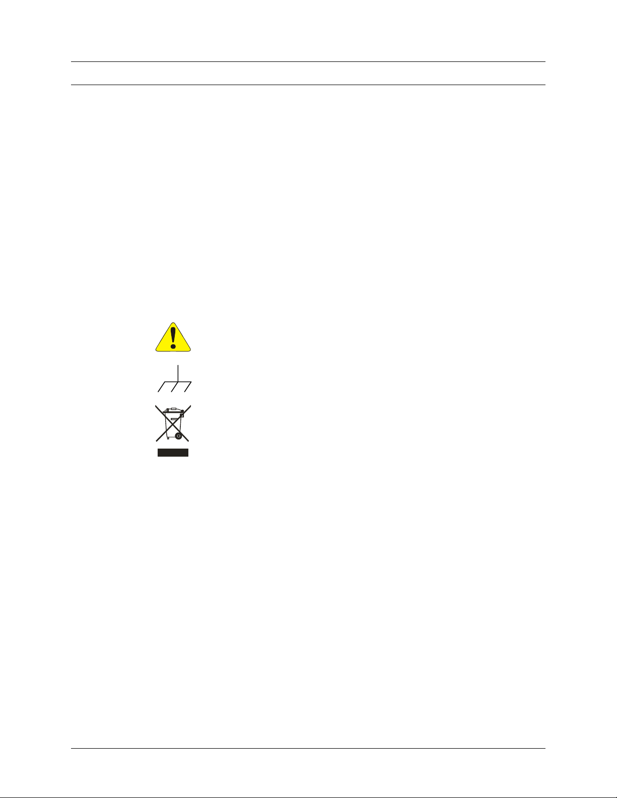
ATTENTION - Important safety instructions
Frame or chassis ground
Indicates that the product was manufactured after August 13, 2005. This mark is
placed in accordance with EN 50419, Marking of electrical and electronic
equipment in accordance with Article 11(2) of Directive 2002/96/EC (WEEE).
End-of-life product can be returned to VTI by obtaining an RMA number. Fees
for take-back and recycling will apply if not prohibited by national law.
WARNINGS
Follow these precautions to avoid injury or damage to the product:
Use Proper Power Cord
The power cable provided with this instrument meets the required
regulatory and statutory safety standards as indicated by this
product’s declaration of conformity. VTI recommends that the power
cord provided be used with the instrument that it is provided with. If
a different power cord is must to be used, however, it is the
responsibility of the user to select a power cord that meets any and
all regulatory and statutory requirements for their industry and
country.
Do not use the power cord supplied with this instrument with any
other equipment.
Use Proper Power Source
To avoid electrical overload, electric shock, or fire hazard, do not use
a power source that applies other than the specified voltage.
The mains outlet that is used to power the equipment must be within
3 meters of the device and shall be easily accessible.
Page 13

www.vtiinstruments.com
EX10xxA Introduction 13
WARNINGS (CONT.)
Avoid Electric Shock
To avoid electric shock or fire hazard, do not operate this product
with the covers removed. Do not connect or disconnect any cable,
probes, test leads, etc. while they are connected to a voltage source.
Remove all power and unplug unit before performing any service.
Service should only be performed by qualified personnel.
Ground the Product
This product is grounded through the grounding conductor of the
power cord. To avoid electric shock, the grounding conductor must
be connected to earth ground.
Operating Conditions
To avoid injury, electric shock or fire hazard:
-
Do not operate in wet or damp conditions.
-
Do not operate in an explosive atmosphere.
-
Operate or store only in specified temperature range.
-
Provide proper clearance for product ventilation to prevent
overheating.
-
DO NOT operate if any damage to this product is suspected.
Product should be inspected or serviced only by qualified
personnel.
Improper Use
The operator of this instrument is advised that if the equipment is
used in a manner not specified in this manual, the protection
provided by the equipment may be impaired.
Conformity is checked by inspection.
Page 14

VTI Instruments Corp.
14 EX10xxA Introduction
SUPPORT RESOURCES
Support resources for this product are available on the Internet and at VTI Instruments customer
support centers.
VTI Instruments Corp.
World Headquarters
VTI Instruments Corp.
2031 Main Street
Irvine, CA 92614-6509
Phone: (949) 955-1894
Fax: (949) 955-3041
VTI Instruments
Cleveland Instrument Division
5425 Warner Road
Suite 13
Valley View, OH 44125
Phone: (216) 447-8950
Fax: (216) 447-8951
VTI Instruments
Lake Stevens Instrument Division
3216 Wetmore Avenue, Suite 1
Everett, WA 98201
Phone: (949) 955-1894
Fax: (949) 955-3041
AMETEK Instruments India Pvt. Ltd.
VTI - Bangalore Instrument Division
Divyasree N R Enclave, Block A,
4th Floor, Site No 1, EPIP Industrial Area,
Whitefield, Bengaluru 560066, India
Phone: +91 (0) 80 6782 3200
Fax: +91 (0) 80 6782 3232
Asia Support
Phone: +852 9177 6127
Technical Support
Phone: (949) 955-1894
Fax: (949) 955-3041
E-mail: [email protected]
Visit http://www.vtiinstruments.com for worldwide support sites and service plan information.
Page 15

www.vtiinstruments.com
EX10xxA Introduction 15
SECTION 1
INTRODUCTION
OVERVIEW
The EX10xxA family of products provides a total of 48-channels, with an exception of RX10xx
products which has 32-channels, of high-performance thermocouple and/or voltage measurement in
a single instrument. This family includes the EX1000A, EX1000A-TC, EX1016A, EX1032A,
EX1048A, EX1000A-51C and RX1032. The last two digits of the model name indicate the number
of thermocouple channels/voltage channels available on the model. For example, the EX1016A has
sixteen thermocouple channels and thirty-two voltage channels. Its combination of measurement
performance and integrity, configuration flexibility, package density, and network connectivity
make it the most powerful, yet easy-to-use, instrument of its kind. The EX10xxA is a complete, selfcontained temperature measurement system that communicates over Ethernet. Unlike other data
acquisition offerings in its class, the EX10xxA offers a tightly integrated solution that frees the user
from the complexity of marrying terminal blocks, signal conditioning cards, digitizer, power supply,
and chassis together.
EX1000A-51C is the enhanced version of the EX10xxA family of products, has 51 Voltage
Channels and has additional features such as additional sensors to measure internal box temperature
and additional API’s provided to read UTC offset & warmup time.
RX10xx is the rugged version of the EX10xxA family of products, has 32 Channels and most
importantly provides the user with the flexibility to place this instrument even in extreme conditions
and directly in the test cells because of its rugged build.
EX1044 is the customized version of the EX10xxA family of products, has 44 TC Channels and 2
channels for voltage/current respectively. This provides thermal labs customers the ability to place
instrumentation directly in the thermal test labs. The EX10xx product has already demonstrated
some of the highest accuracy in the market for Thermocouple measurements and the EX1044 will
continue to provide as good or better accuracy for gas turbine test cell users trying to improve engine
efficiency by better understanding temperature effects on the DUT.
The EX10xxA also provides a level of measurement integrity and channel independence that far
exceeds the typical data acquisition system. Absent are caveats about scanning speed, channel order,
and overload effects. In the EX10xxA, channels have no influence on each other, regardless of
scanning speed or channel state. Excellent common mode rejection performance provides immunity
from not only power line interference, but also high frequency noise. Moreover, it aids in
maintaining overall system integrity by offering a high-performance open transducer detection
system.
The EX10xxA provides a high level of configuration flexibility as well. Each channel can be
configured independently with regards to measurement function, hardware filter setting, and limit
values. In addition to measuring all standard thermocouples, the EX10xxA can be programmed with
Page 16

VTI Instruments Corp.
16 EX10xxA Introduction
user-defined thermocouple polynomial equations or be used as a low-noise voltmeter. Scanning
speed is programmable up to a maximum of 1 kSa/s, independent of the number of channels being
scanned. This combination of filtering and scanning speed provides the EX10xxA with the low noise
performance required for sensitive applications as well as the speed necessary to measure fast, finegauge thermocouples.
For highest accuracy and stability, the EX10xxA provides an embedded isothermal input section
that is monitored by up to twelve precision thermistors (depending on model), one for every four
thermocouple channels. Moreover, it features an internal calibration source that can be used to self-
calibrate the unit upon command. This extends the unit’s high accuracy over a wide ambient
temperature range. Thermocouple accuracy is detailed in Table 1-2.
The EX10xxA is as easy-to-use as it is powerful. An integrated web page provides a convenient
way to instantly verify communications and instrument functionality, while industry standard VXI
plug & play and IVI drivers provide a familiar application programming interface to reduce
integration and program development time.
FEATURES
Combined Thermocouple and Analog Inputs
Easily combine thermocouple and analog signals on these versatile instruments with sampling rates
up to 1 kSa/s (kilo samples per second) per channel. Each input incorporates an independent signal
conditioning path with software selectable filters for maximum flexibility. Complete channel
independence ensures data integrity regardless of sample speed or input overload conditions.
End-to-end Self-calibration
Complete end-to-end self-calibration is provided for each signal path on a programmable basis. A
highly accurate calibration source provides reference signals that are applied prior to analog filtering
and gain circuits to compensate for drift, aging, or temperature variations. Self-calibration is simple
and quick, and can be performed as often as desired.
Scalable for Synchronized High-Speed, High-Channel Count
With LXI™ Class A compliant features like a built-in Trigger Bus™ hardware trigger subsystem,
the EX10xxA supports easy integration and synchronization of multiple devices, including existing
VXI bus instrumentation.
Open Thermocouple Detection (OTD)
While the integration of the EX10xxA removes many of the reliability and connectivity problems
typically faced by system designers, they still must contend with the reliability of the sensor
connections. Fortunately, the EX10xxA aids a great deal in that regard as well. Each thermocouple
input channel generates a very small current (±7.5 nA/channel) which drives the input to an opencircuit state if the transducer is disconnected. Implemented in this way, open transducer detection is
continuous and requires no discrete function call on the part of the user to be activated, offering
more protection than systems that only check on command, as a broken sensor can occur at any time
during testing, not just at installation. In a typical application, the OTD has no effect on the
measurement. However, many thermocouple simulators have a much higher impedance than a
thermocouple so an offset may be introduced into the reading when using a simulator. In general,
the OTD should only be active on channels that are being used with actual thermocouples.
The EX10xxA additionally offers a front panel OTD LED for each channel that illuminates upon
the recognition of a fault condition. This provides for quick and easy problem channel identification.
Moreover, to ensure that even intermittent problems are identified, the fault recognition is a latching
mechanism, retaining the information of the current acquisition sequence until a new acquisition is
initiated. Note that voltage channels do not include internal CJC thermistors, but that each voltage
D-sub includes connections for the connection of user-supplied thermistors.
Page 17

www.vtiinstruments.com
EX10xxA Introduction 17
Note: OTD functionality will not be applicable for EX1000A-51C. RX1032 doesn’t have option to
provide OTD LED indication in a fault condition due to its rugged design.
Cold Junction Compensation (CJC)
For highest accuracy and stability, the EX1000A-TC, EX1016A, EX1032A, EX1048A RX1032
provide embedded isothermal input sections that are monitored by precision thermistors (based on
Model#, the number of thermistors can vary), one for every four thermocouple channels. (Note, the
EX1000A may utilize external thermistors as described in the Voltage Connections section). To
ensure that the CJC information is current and time correlated with the input channels, the CJC
channels are measured with every scan, providing a maximum time separation of less than 4 ms
between the measurement of an input channel and its associated CJC measurement. For those users
that prefer to employ an external cold junction, the EX10xxA also allows for the programming input
of up to forty-eight unique external cold junction temperatures, one for every input channel.
Moreover, the use of internal and external CJC inputs can be mixed throughout the unit on a per
channel basis.
Simplified Installation, Setup and Control
Full LXI Class A compliance makes the EX10xxA of instruments ideal for distributed
measurements throughout a facility – reducing cabling and installation expense. Connect directly to
an Ethernet network using industry standard Ethernet cable and connections. Experience how
plug&play capability simplifies installation and setup.
An onboard, web-accessible user interface allows you to instantly verify communications and
instrument functionality, while IVI and VXI plug&play drivers provide a familiar application
programming interface to further reduce integration and program development time. For
comprehensive, programming-free data recording setup, management and viewing, use EX10xxA
instruments with one of VTI’s full-featured, turnkey software solutions: EXLab or VTICODA.
Channel Independence
Each of the EX10xxA’s 48 differential input channels is an independent signal conditioning path,
complete with amplification, programmable hardware filtering, and continuous open transducer
detection. This independence frees the user from the problem of channel-to-channel crosstalk that
is pervasive in most multi-channel data acquisition systems. In the EX10xxA, channels have no
influence on each other, regardless of scanning speed or channel state. Specifically, open or
significantly overloaded channels do not affect the measurement results of any other channels.
Measurement Range
The measurement range of the EX10xxA in terms of temperature is a function of its input voltage
range and the capabilities of the thermocouple sensors themselves. Specifically, the measurement
range of the EX10xxA for the standard thermocouple types is the following:
Type
Min Temp
Max Temp
J
-200 °C (-328 °F)
1200 °C (2192 °F)
K
-200 °C (-328 °F)
1372 °C (2502 °F)
T
-200 °C (-328 °F)
400 °C (752 °F)
E
-200 °C (-328 °F)
900 °C (1652 °F)
S
-50 °C (-58 °F)
1768 °C (3214 °F)
R
-50 °C (-58 °F)
1768 °C (3214 °F)
B
250 °C (482 °F)
1820 °C (3308 °F)
N
-200 °C (-328 °F)
1300 °C (2372 °F)
TABLE 1-1: EX10XXA MEASUREMENT RANGE
Page 18

VTI Instruments Corp.
18 EX10xxA Introduction
In terms of voltage, the thermocouple connectors may only accept an input voltage of ±67 mV when
performing temperature conversion. When in voltage mode, these connectors can accept either
±0.067 V or ±0.1 V inputs. The voltage connectors may use either ±0.01 V, ±0.067 V, ±0.1 V,
±1.0 V, or ±10.0 V inputs for both EU temperature conversion or voltage measurements. When
temperature is selected, the instrument automatically switches the selected channel(s) to the ±67 mV
range. The EX1000A-TC is a special case where thermocouple inputs are used for voltage
measurement and may utilize all input ranges available to the voltage connectors. Table 1- provides
an overview of each models capabilities.
For maximum flexibility, each channel can be independently configured with regards to its
thermocouple conversion. Moreover, non-standard thermocouples are accommodated through the
input of user-defined thermocouple polynomial coefficients.
Hardware Filter
Each EX10xxA input channel can be individually configured with one of six low-pass hardware
filters. Five of these filters are 2-pole Bessel filters with frequencies of 4 Hz, 15 Hz, 40 Hz, 100 Hz
and 500 Hz. The sixth filter is a single-pole Butterworth filter with a frequency of 1 kHz, providing
a simple anti-alias filter when the 1 kSa/s range is used. These filters allow the EX10xxA to cover
a diverse range of applications, even within the same unit. Suitable for most applications, the 4 Hz
setting provides the lowest noise floor and exceptional common mode rejection. For higher speed
applications, the 1 kHz filter will pass the output from even the fastest fine-gauge thermocouples
with little distortion.
Input Connectors
The EX1016A, EX1032A, and EX1048A employ uncompensated (Cu-Cu) mini-thermocouple
female jacks as an input connector. This connector provides a solid, reliable connection that is also
easily changeable. Since it is not thermocouple-type specific, different thermocouple types can be
mixed throughout the unit without hardware modification. The EX1000A, EX1016A and EX1032A
also employ a standard 50-pin D-sub connector for the voltage input channels. All the RX10xx
channels are individually routed via the screw terminals which is placed just below the instrument
top cover and the cable bunch is brought out through the cable gland.
Sampling Rate
The EX10xxA can be configured for a sampling rate up to a maximum of 1 kSa/s, regardless of the
number of channels included in the scan list. When the requested sampling rate is significantly less
than 1 kSa/s, however, the EX10xxA automatically takes and averages multiple samples. This offers
improved noise performance, while maintaining the requested data output rate.
Digital I/O and Limits
The EX10xxA provides two unique sets of programmable limits that are used for open transducer
detection as well as general purpose input channel monitoring. These limits are programmable on a
per channel basis and are evaluated with each completed scan. The output of limit evaluations is
presented in three forms. The operation of the front panel LEDs is tied to the upper and lower limit
values of one limit set. The operation of the digital I/O port can be optionally linked to any
combination of the upper and lower limit values of either or both limit sets. Finally, the limit
condition information is accessible through the instrument driver.
The EX10xxA features an 8-channel digital I/O port on the rear panel of the instrument, except
RX10xx which has 2-channel digital I/O routed through the 13 pin circular connector (P1). This
port can be used as an arm/trigger source, for presentation of limit evaluation information, and as a
general purpose output device. As a general purpose output device, each DIO channel can be
independently programmed with regards to its output functionality and its static level to assume
when enabled as an output. For expanded and more automated operation, each DIO channel can be
independently linked to one or multiple limit conditions on one or more input channels.
Page 19

www.vtiinstruments.com
EX10xxA Introduction 19
LXI Trigger Bus
The EX10xxA features an 8-channel LXI (LAN eXtensions for Instrumentation) trigger bus on the
rear panel of the instrument. This differential-pair LVDS (Low Voltage Differential Signal) bus
consists of two identical ports connected in parallel. The primary use of the trigger bus is the
transmission of high-speed signals for multiple-unit triggering and synchronization.
Note: RX1032 doesn’t have LXI trigger bus.
Triggering
The EX10xxA supports a full function trigger model with a separate arm source and trigger source
event structure. Trigger and arm source events can be independently programmed from a variety of
sources including Immediate, Timer, Digital I/O, LAN events, the LXI Trigger Bus, and the LXI
alarm.
EX10XXA SPECIFICATIONS
GENERAL SPECIFICATIONS
NUMBER OF CHANNELS
EX10XXA
EX10XXA-51C
RX10XX
EX1044
48 differential inputs
51 differential inputs
32 differential inputs
48 differential inputs
CHANNEL TYPES
Thermocouple and voltage
J, K, T, E, S, R, B, N (EX1000A-TC, EX1016A, EX1032A, EX1048A, RX1032,
EX1044)
mV (RX1032), V (EX1000A, EX1000A-TC, EX1016A, EX1032A, EX1000A-51C,
EX1044, RX1000)
mA, A (EX1044)
SAMPLING RATE
1000 Sa/s per channel maximum
TEMPERATURE RESOLUTION
0.1 °C
TEMPERATURE ACCURACY
See Table 1-2 below
TEMPERATURE NOISE
Peak-to-peak
0.08 °C typical (J, K, T, E)
PROGRAMMABLE FILTERS
Bessel (2 pole)
Butterworth (1 pole)
4 Hz, 15 Hz, 40 Hz, 100 Hz, and 500 Hz (-3 dB cutoff frequency)
1000 Hz (-3 dB cutoff frequency)
VOLTAGE INPUT RANGE
Voltage input channels
Thermocouple input channels
±0.01 V, ±0.067 V, ±0.1 V, ±1.0 V, ±10.0 V
±0.067 V for temperature measurement, ±0.067 V and ±0.1 V for voltage measurement.
INPUT POWER
Input voltage/frequency
Power
90 V ac – 264 V ac*, 50 Hz/60 Hz (nominal ac)
47 VA
*Note, fluctuations for mains voltage to the power supply not exceeding 10% of the nominal voltage.
VOLTAGE RESOLUTION
±10.0 V
±1.0
±0.1 V
±0.067 V
±0.01 V
300 µV
30 µV
3.0 µV
2.0 µV
0.3 µV
VOLTAGE ACCURACY
± ( % of reading + offset )
±10.0 V
±1.0 V
±0.1 V
±0.067 V
±0.01 V
± (0.025% + 500 µV) with self-cal*, ± (0.05% + 1 mV) without self-cal*
± (0.025% + 50 µV) with self-cal*, ± (0.05% + 100 µV) without self-cal*
± (0.025% + 10 µV) with self-cal*, ± (0.05% + 20 µV) without self-cal*
± (0.025% + 10 µV) with self-cal*, ± (0.05% + 20 µV) without self-cal*
± (0.050% + 10 µV) with self-cal*, ± (0.10% + 20 µV) without self-cal*
Page 20

VTI Instruments Corp.
20 EX10xxA Introduction
GENERAL SPECIFICATIONS
*Note, self-cal is not applicable for RX1032
VOLTAGE OFFSET STABILITY
±10.0 V
±1.0 V
±0.1 V
±0.067 V
±0.01 V
± 20 µV/°C typical
± 10 µV/°C typical
± 5 µV/°C typical
± 2 µV/°C typical
± 2 µV/°C typical
VOLTAGE GAIN STABILITY
Voltage input channels (all ranges)
and thermocouple input channels
*Note, self-cal is not applicable for RX1032
± 25 ppm/°C without self-cal* (typical)
± 5 ppm/°C with self-cal* at any operating temperature (typical)
INPUT IMPEDANCE
40 MΩ differential
INPUT BIAS CURRENT
5 nA typical
COMMON MODE INPUT RANGE
±10 V
COMMON MODE REJECTION RATIO (CMRR)
4 Hz filter
1 kHz filter
dc: 100 dB minimum; (50/60) Hz: 140 dB typical, 120 dB minimum
dc: 100 dB minimum; (50/60) Hz: 100 dB typical, 80 dB minimum
See Figure 7-2 in the Theory of Operation for more information regarding CMRR.
INPUT PROTECTION
±15 V
NETWORK CONNECTION
10/100 Base-T
INPUT CONNECTORS
Thermocouple
EX10xxA
RX10xx
Analog voltage
EX10xxA
EX1000A-51C
EX1000A-TC
Cu-Cu mini-TC jack
Screw terminals (three terminals for each channels “S, +, -“) M3 X 6MM (PAN HEAD PHILLIPS)
50-pin female D-sub
50-pin female D-sub
Cu-Cu mini-TC jack
OPERATING TEMPERATURE (FOR EX10XX A)
0 °C to 50 °C
POWER INPUT (EX10XXA, 51C)
EX10xxA
RX10xx
(90 – 264) V ac, (50/60) Hz
INPUT VOLTAGE DC, 18-36V DC
DIMENSIONS ( EX10XXA/RX10XX )
EX10xxA
EX1000A-51C
RX10xx
1.75’’ H x 17.5’’ W x 13.6’’D
1.75’’ H x 17.5’’ W x 13.6’’D
4.92” H x 9.05” W x 9.45” D; 125 x 238 x 249 mm (including handles and latches)
WEIGHT (RX10XX )
RX10xx
5.3 KG; 11 lbs
RELIABILITY (EX10XXA)
MTBF
Methodology
> 100,000 hrs (or approximately 11 years)
Telcordia (Bellcore) SR-332, Issue 1
LXI SPECIFICATIONS
LXI CLASS COMPLIANCE
LXI Class A
CLOCK SPECIFICATIONS
Clock oscillator accuracy
Synchronization accuracy
Timestamp
Accuracy
Resolution
±50 ppm
Reports “synchronized” when < ±200 µs of the 1588 master clock
As good as time synchronization down to 50 ns
25 ns
IEEE 1588-BASED TRIGGER TIMING
Alarm
Page 21

www.vtiinstruments.com
EX10xxA Introduction 21
Trigger time accuracy
Time to trigger delay
Receive LAN[0-7] Event
Trigger time accuracy
Time to trigger delay
Future timestamp
Past/zero timestamp
As good as time synchronization down to 50 us
50 us
As good as time synchronization down to 50 us
50 us typical
1 ms maximum
HARDWARE TRIGGER TIMING
LXI Trigger Bus
Time to trigger delay
DIO Bus
Time to trigger delay
55 us typical
57 us typical
ENVIRONMENTAL SPECIFICATIONS FOR EX10XXA, EX1000A-51C
OPERATING LOCATION
This chassis should be operated indoors in a controlled environment, protected from
exposure to the elements (i.e. direct sunlight, precipitation, wind, etc.).
TEMPERATURE
Operating
Storage
0 C to +50 C
-40 C to +70 C
HUMIDITY
5% – 95% (non-condensing)
ALTITUDE
Up to 3000 m
SHOCK AND VIBRATION
Conforms to MIL-PRF-28800F, Paragraphs 4.5.5.3.1 (random vibration test), 4.5.5.3.2
(sinusoidal vibration test), and 4.5.5.4.1 (functional shock test)
ENVIRONMENTAL SPECIFICATIONS FOR RX10XX
TEMPERATURE
-40°C TO +71°C (REDUCED ACCURACY), 0°C TO +50°C (FULL ACCURACY)
HUMIDITY
IP 65 RATED ENCLOSURE, 5% TO 95%
ALTITUDE
UP TO 4600 M
SHOCK AND VIBRATION
CONFORMS TO MIL-PRF-28800F
RANDOM VIBRATION 30 MIN PER AXIS, 10-500Hz MIL-PRF-28800F CLASS 2
SINUSOIDAL 5 TO 55HZ RESONANCE SEARCH PER MIL-PRF-28800F CLASS 2,
EACH AXIS SHOCK 30G/AXIS, 11MS HALF SINE PULSE PER MIL-PRF-28800F
CLASS 2
CHASSIS MOUNTING
6 X M6 X 10mm LG, CAP FLANGE HD, 10.9 STEEL SCREWS
ENVIRONMENTAL SPECIFICATIONS FOR EX1044
TEMPERATURE
-10°C TO +45°C (REDUCED ACCURACY), 0°C TO +50°C (FULL ACCURACY)
HUMIDITY
5% – 95% (non-condensing)
ALTITUDE
Up to 3000 m
SHOCK AND VIBRATION
Conforms to MIL-PRF-28800F, Paragraphs 4.5.5.3.1 (random vibration test), 4.5.5.3.2
(sinusoidal vibration test), and 4.5.5.4.1 (functional shock test)
CHASSIS MOUNTING
TABLE TOP MOUNTING
Page 22
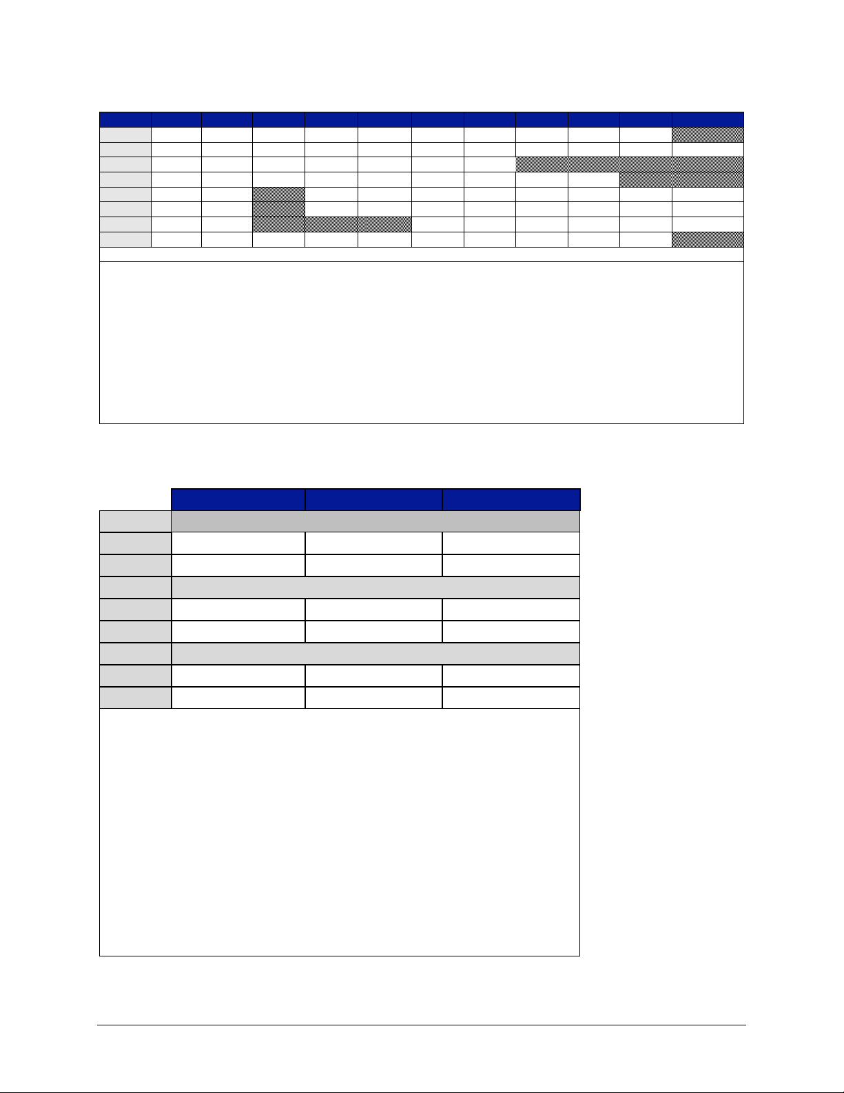
VTI Instruments Corp.
22 EX10xxA Introduction
TABLE 1-2: THERMOCOUPLE ACCURACY FOR EX10XXA (TYPICAL)
Type
Min
Max
-100 0 100
300
500
700
900
1100
1400
J
-200
1200
±0.25
±0.20
±0.20
±0.25
±0.30
±0.30
±0.35
±0.45
K*
-200
1372
±0.25
±0.20
±0.20
±0.20
±0.35
±0.35
±0.45
±0.55
±0.50
T**
-200
400
±0.25
±0.20
±0.20
±0.20
±0.25 E -200
900
±0.25
±0.20
±0.20
±0.20
±0.25
±0.30
±0.35 S -50
1768
±1.00
±0.75
±0.65
±0.65
±0.65
±0.70
±0.70
±0.75
R
-50
1768
±1.00
±0.75
±0.60
±0.60
±0.60
±0.60
±0.65
±0.70
B
250
1820 ±1.65
±1.10
±0.80
±0.70
±0.65
±0.65
N
-200
1300
±0.40
±0.25
±0.25
±0.25
±0.30
±0.35
±0.40
±0.40
Values in °C
Conditions
• 60 minute warm-up
• Guaranteed maximum limits are two times (2x) the typical values
• 7 days, ±5 °C from last self-calibration***
• 20 °C to 30 °C, 1 year from full calibration
• Exclusive of thermocouple errors
• Exclusive of noise
• Common mode voltage = 0
* 1400 accuracy is for 1372 °C
** 500 accuracy is for 400 °C
TABLE 1-3: THERMOCOUPLE ACCURACY FOR RX1032
-40 °C to +50 °C
+50 °C to +70 °C
+15 °C to +25 °C
Type E, J, K, N & T
Typical
±0.22°C
±0.53°C
±0.12°C
Max
±0.35°C
±0.93°C
±0.20°C
Type R & S
Typical
±0.88°C
±2.12°C
±0.48°C
Max
±1.40°C
±3.72°C
±0.80°C
Type B
Typical
±1.76°C
±4.24°C
±0.96°C
Max
±2.80°C
±7.44°C
±1.60°C
Note: Typical is based on 2σ & Max is based on 4σ
Conditions
• After 1 hour warmup period and temperature stable for 1 hour after any temperature change.
• Accuracy does not include accuracy of thermocouple or thermocouple wiring.
• Maximum Temperature rate of change between any operating temperature is 0.5 °C/min
• Guaranteed maximum limits are two times (2x) the typical values
• 7 days, ±5 °C from last calibration
• -20 °C to +30 °C, 1 year from full calibration
• Exclusive of thermocouple errors
• Exclusive of noise
• Common mode voltage = 0
• Self calibration is not applicable
Temperature rate of change
• Nominal - 0.33 °C /min
• Max - 1.33 °C /min
Page 23
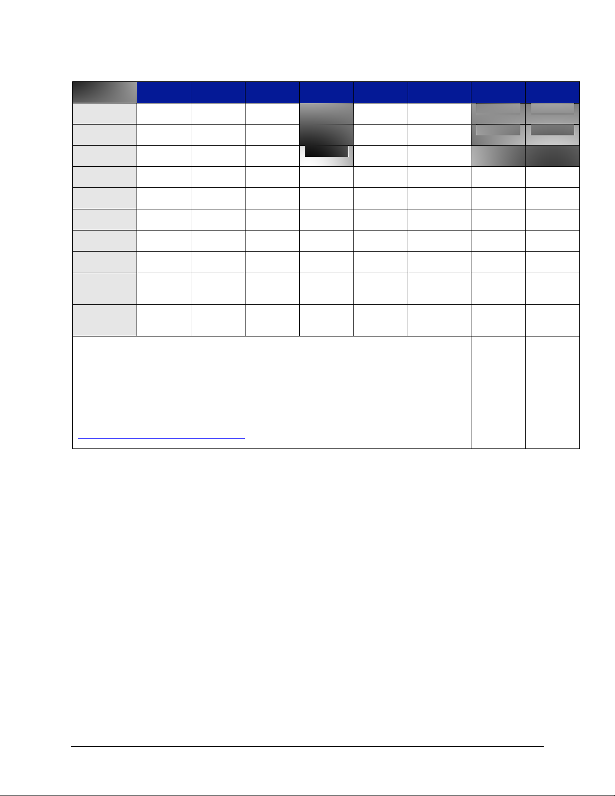
www.vtiinstruments.com
EX10xxA Introduction 23
TABLE 1-4: EX10XXA/RX10XX CONFIGURATIONS
EX1000A
EX1016A
EX1032A
EX1048A
EX1000A-
TC
EX1000A-
51C
RX1032
EX1044
±10 V Range
48 channels
32 channels
1,2,3
16 channels
1,2,3
48 channels
51 channels
±1.0 V Range
48 channels
32 channels
1,2,3
16 channels
1,2,3
48 channels
51 channels
±0.1 V Range
48 channels
48 channels
48 channels
48 channels
51 channels
±0.067 V
Range
48 channels
48 channels
48 channels
48 channels
48 channels
51 channels
32 channels
44 channels
±0.01 V
Range
48 channels
32 channels
1,2,3
16 channels
1,2,3
48 channels
48 channels
51 channels
32 channels
44 channels
TC
Connectors
0
16
32
48
48 0 0
44
Internal
CJCs 4
0 4 8
12
12 0 8 11
External
CJCs 5
3 2 1 0 0 0 0
0
Voltage
Channel
0 0 0 0 0 0 0
2 channels
(0-300V
AC)*
Current
Channel
2 channels
(0-5A
AC)*
Notes
1
D-sub connector inputs can be configured for all voltage ranges.
2
D-sub connector inputs can be configured for thermocouple measurement provided the external CJC sensor is wired
and activated.
3
Thermocouple connector inputs can be configured for 0.067 V, 0.1 V, or thermocouple measurement. The EX1000ATC is an exception, as it provides 48 thermocouple connectors capable of performing measurements on all voltage
ranges indicated above.
4
For thermocouple connector inputs, there is one internal CJC sensor for each group of four channels.
5
For D-sub connector inputs, there is one external CJC sensor connection (10,000 Ω thermistor) for all 16 channels.
* For EX1044 accuracy refer SCM5B 33-05 & SCM5b33-07 Dataforth module website i.e.
http://www.dataforth.com/signal-conditioning.aspx for voltage & current channels respectively
Page 24
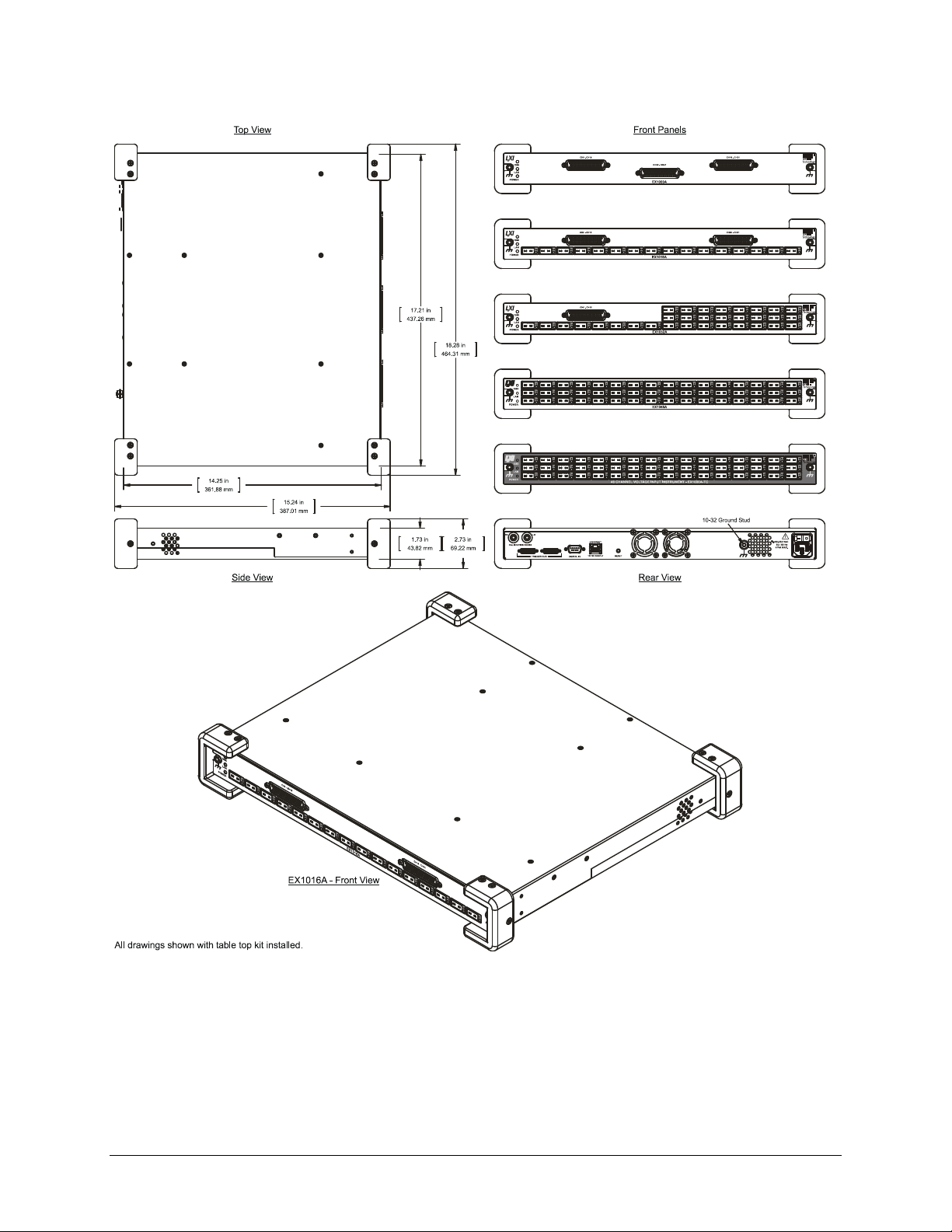
VTI Instruments Corp.
24 EX10xxA Introduction
EX10XXA DIMENSIONAL DIAGRAM
FIGURE 1-1: RACKMOUNT HARDWARE INSTALLATION DIAGRAM
Page 25
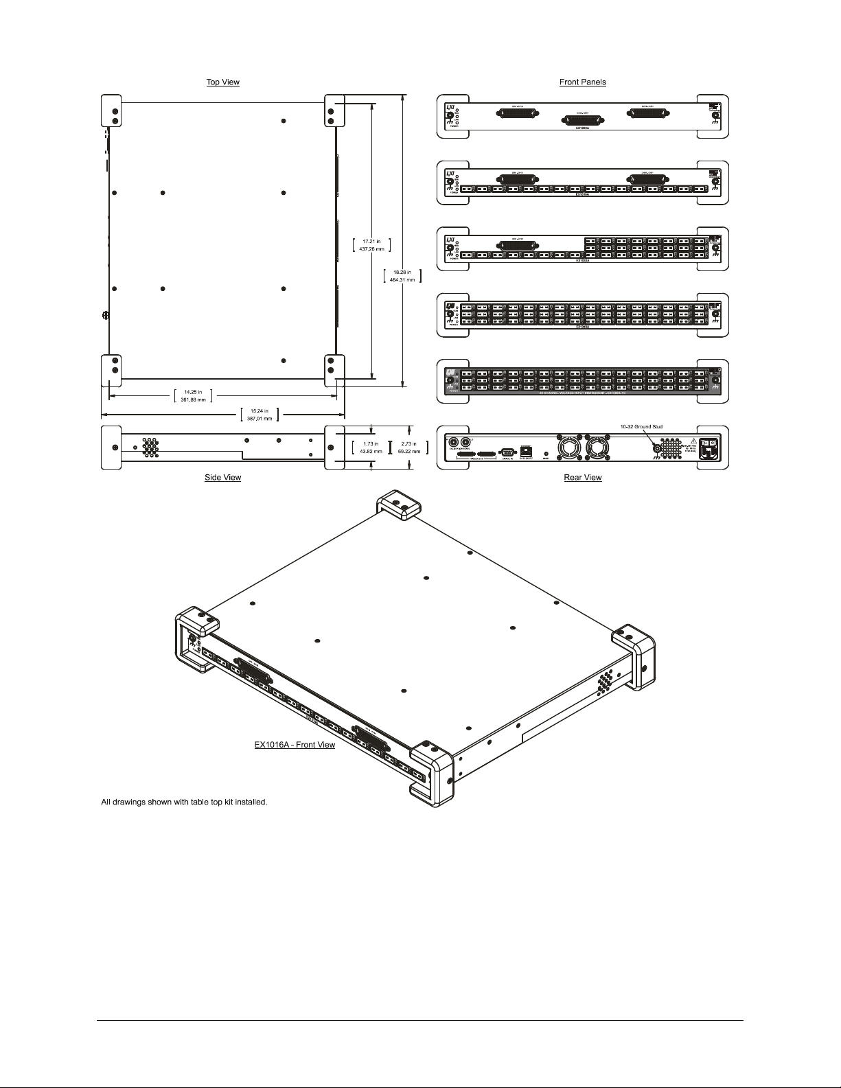
www.vtiinstruments.com
EX10xxA Introduction 25
FIGURE 1-2: RACKMOUNT HARDWARE INSTALLATION DIAGRAM
Page 26
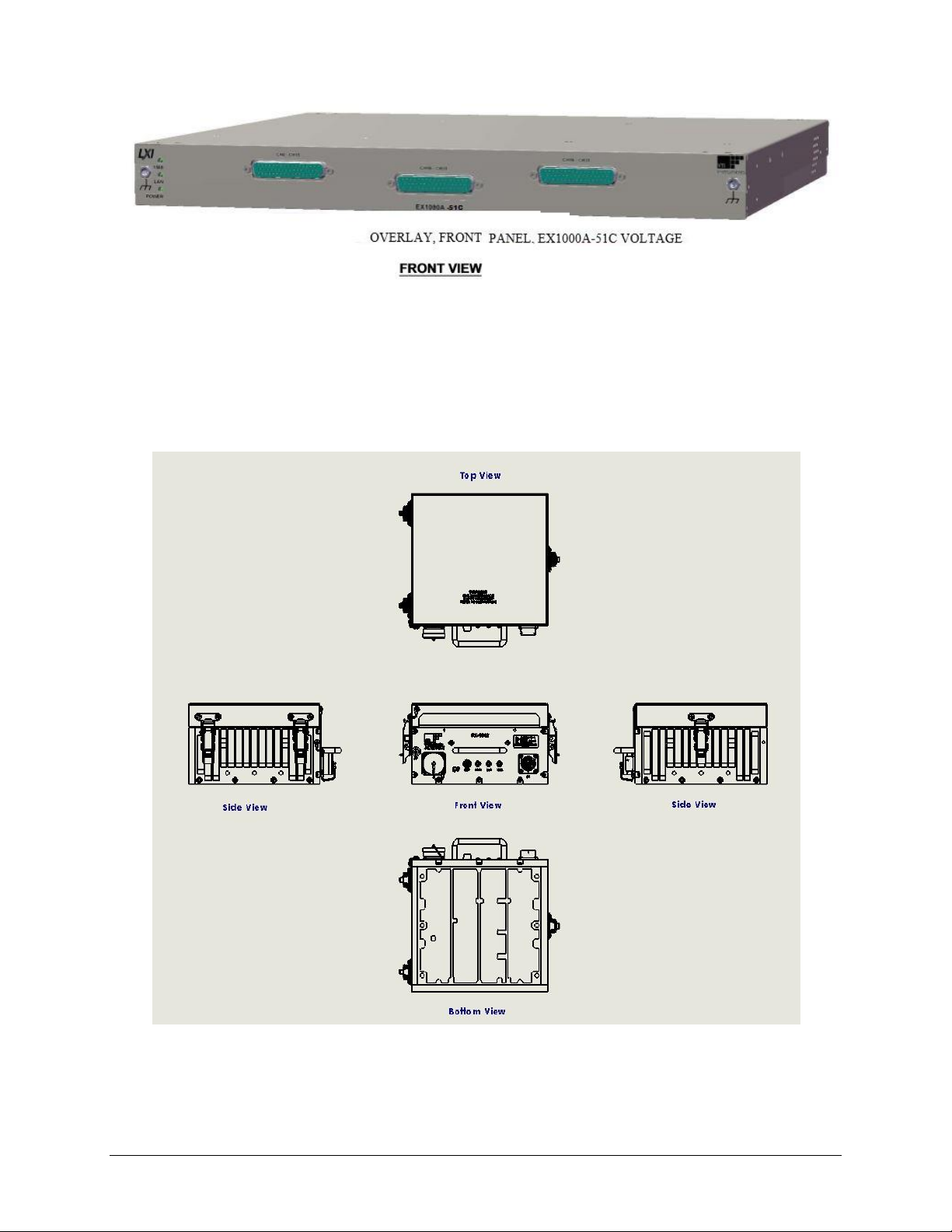
VTI Instruments Corp.
26 EX10xxA Introduction
FIGURE 1-2A: EX1000A-51C
RX1032 DIAGRAM
FIGURE 1-3: RACKMOUNT HARDWARE INSTALLATION DIAGRAM
Page 27

www.vtiinstruments.com
EX10xxA Introduction 27
FIGURE 1-4: ISOMETRIC AND INTERNAL CJC PLATE DIAGRAM
Page 28
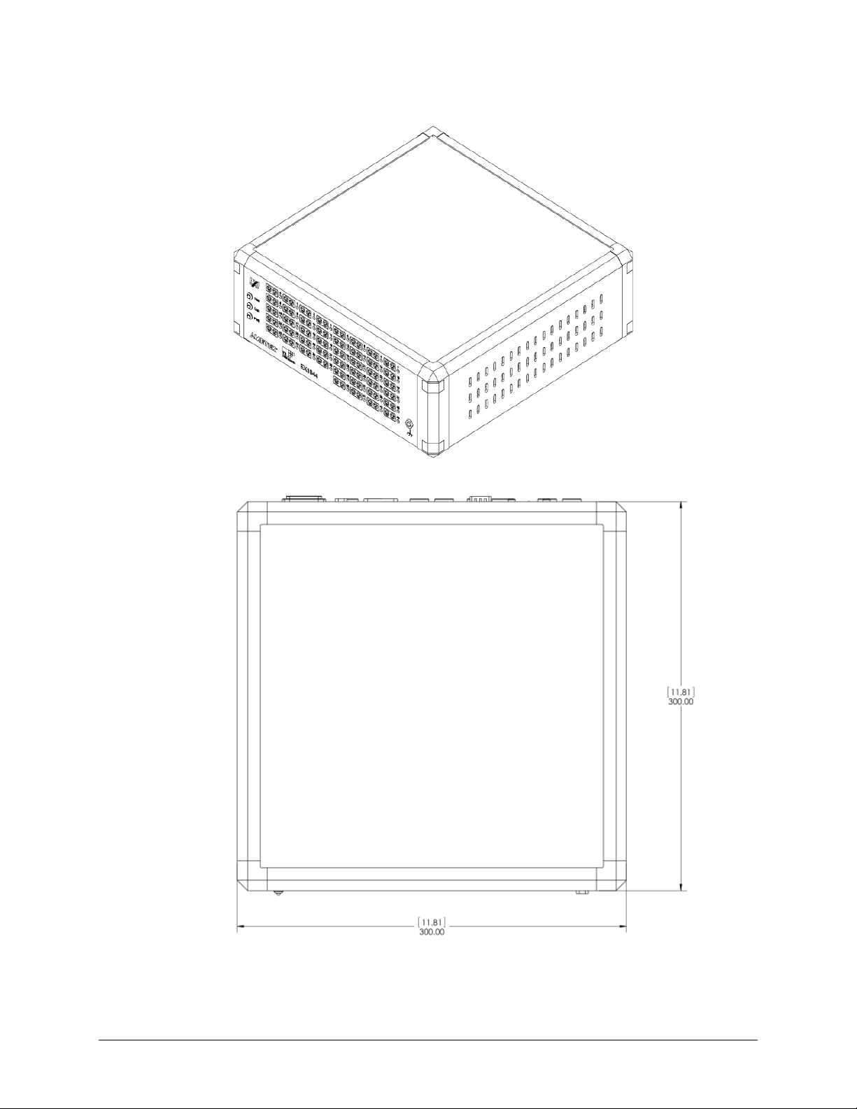
VTI Instruments Corp.
28 EX10xxA Introduction
EX1044 DIAGRAM
Page 29
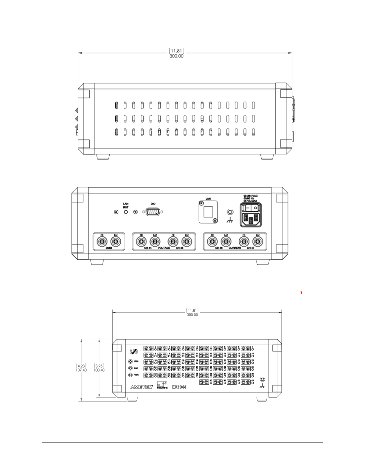
www.vtiinstruments.com
EX10xxA Introduction 29
FIGURE 1-5: EX1044 TABLE TOP USAGE
Page 30

VTI Instruments Corp.
30 EX10xxA Introduction
EXPLANATION OF SPECIFICATIONS
The base accuracy of the EX10xxA is specified over an ambient operating temperature range of
20 ºC to 30 ºC and within one year of full calibration. This accuracy is shown in Table 1-2.
Significant performance improvement over the base accuracy can be realized, however, using
periodic self-calibration. Note, however, that the base ambient operating temperature range and full
calibration time interval restrictions still apply.
The EX10xxA’s thermocouple accuracy table provides the user with an easy-to-use description of
the unit’s capabilities at several points over the valid input dynamic range of the instrument. Each
specific thermocouple type is represented by a different row. Each column refers to an input
temperature of that value. For example,, an input temperature of 100 ºC on a type K thermocouple
has a maximum instrument uncertainty of ±0.20 ºC, exclusive of thermocouple errors.
Exclusive of thermocouple errors
The “exclusive of thermocouple errors” qualification refers to two inherent sources of error present
in all thermocouples to some extent. The first, and most obvious, error source is the accuracy of the
thermocouple itself. This refers to the extent to which the specific thermocouple potentially deviates
from the standardized International Temperature Scale of 1990 (ITS-90) characteristic for its
thermocouple type. The second, less obvious error source relates to the resistance of the
thermocouple wire, which creates a voltage drop against the input bias current of the EX10xxA. In
most applications, this error effect is negligible. However, if the length and wire gauge of the
employed thermocouple represents a resistance over 250 Ω, its effect should be analyzed for
significance.
As an example, 650 ft of 24 gauge type T wire has a resistance of about 500 Ω. Against the
EX10xxA’s typical input bias current of 7.5 nA, this creates a voltage error of:
V 3.75nA 7.5Ω 500
To convert this error to its representative temperature error, it is then divided by the slope of the
thermocouple characteristic at the temperature of interest. For example, the slope of the type T
characteristic at 0 ºC is 39 µV/ºC. The error at this point is then:
C 0.1CV/ 93V 3.75
Common mode rejection
The common mode rejection characteristics of the EX10xxA are specified in terms of dB for both
dc and (50/60) Hz interference. It should be noted that these specifications refer to the distortion of
the measurement in terms of voltage, not temperature. The following example illustrates how to
determine the possible temperature error for a T type thermocouple measuring 0 ºC due to a 1 V dc
common mode signal.
The EX10xxA has a minimum CMRR at dc of 100 dB. A 1 V common mode voltage creates a
maximum differential voltage error of:
V 10
10
V 1
20
100
As before, this voltage error converts to a temperature error by dividing by the appropriate
thermocouple slope to yield a maximum error of:
C 0.26CV/ 39V 10
Page 31

www.vtiinstruments.com
EX10xxA Introduction 31
MAXIMIZING MEASUREMENT PERFORMANCE
This section discusses tips and procedures that can help maximize the actual performance realized
with the EX10xxA and aid the user in avoiding some common pitfalls associated with thermocouple
measurement.
Utilize self-calibration
Self-calibration should be conducted as often as practical, especially if the ambient environment has
changed significantly since the previous calibration. However, fast ambient environmental changes
should ideally be followed by a period of thermal stabilization before conducting self-calibration.
The self-calibration process completes quickly and does not require removal of the actual input
connections, making it convenient to run often.
NOTE Self calibration is not applicable for RX10xx since during factory calibration process each
instrument will be calibrated in precise manner and calibrated data gets stored in the instrument
memory. The instrument has to be sent to factory to perform subsequent calibration after the initial
calibration date is expired. Refer below section for Dynamic Calibration in RX1032
Dynamic Calibration in RX1032
The dynamic calibration should be conducted to calibrate the measurement drift due to the
temperature change. For every measurement scan, the values are adjusted based on the system
internal temperature.
The initial calculated Voltage and Temperature coefficients are stored into the RX1032
system.
At every measurement the measured values are calibrated dynamically using the stored
coefficients.
Based on the present temperature of the system, the values are calibrated and reported.
Utilize self-test
Self-test should be conducted to check the working condition of CJC thermistor. Generally it should
be followed after self-calibration However at least 30 minutes warm up time should be sufficient
enough before conducting self-test. The self-test process takes at least 2 minutes for completion and
does not require removal of the actual input connections, making it convenient to run often. After
every self-test operation the unit should be stabilized for at least 30 minutes.
Allow for cold junction thermal stabilization
The performance of any thermocouple measurement instrument is largely determined by the
stability of the cold junction sensing mechanism. For maximum accuracy and stability, the
EX10xxA is designed with a significant thermal mass that connects the input connectors to the cold
junction sensing element. However, while this lowers the sensitivity to thermal disturbances,
transient measurement errors are still possible under certain operating conditions. Awareness of
these conditions will help achieve the maximum performance from the EX10xxA.
Step change in ambient temperature
If the EX10xxA is subjected to a significant ambient temperature change over a short period of time,
a transient measurement error will occur due to the inherent thermal time constant differences
between the thermal mass and the actual cold junction made between the EX10xxA input connector
and the type-specific thermocouple connector. The magnitude of the error will be directly
proportional to the rate of change of the ambient temperature. Because the actual cold junction is
more closely tied to the external ambient conditions than the internal thermal mass, it will follow
the ambient temperature change to a slightly better extent than the thermal mass. Consequently,
when subjected to a drastic rise in ambient temperature, the actual cold junction will rise in
Page 32
VTI Instruments Corp.
32 EX10xxA Introduction
temperature at a slightly faster rate than the thermal mass (and thus cold junction measurement). In
this case, the channel measurements will show a transient error of negative polarity. Conversely, if
the ambient temperature drastically falls, the channel measurements will show a transient error of
positive polarity. In either case, as the rate of ambient temperature change decreases, thermal
equilibrium is regained, and the error is eliminated. This error mechanism is not affected by
calibration and is avoided by allowing for an appropriate thermal equilibrium delay.
NOTE Significant ambient temperature changes should be followed by a thermal equilibrium delay before
the initiation of measurements.
Initial insertion of a jack / screw terminal connection
A similar error mechanism is introduced when a male thermocouple jack / wire connected to screw
terminal is first inserted into an EX10xxA/RX10xx input channel. A transient error is generated
because the male thermocouple jack and mating female jack on the EX10xxA are at different
temperatures when they make first contact. If both the unit and male jack are at the same ambient
temperature, this error typically dissipates to less than 0.1 ºC within 3 minutes. However, a jack at
room temperature plugged into a unit that is at a substantially different ambient temperature will
generate a significantly larger initial error that takes longer to decay to a level of insignificance. This
error mechanism is not affected by calibration and is avoided by allowing for a thermal equilibrium
delay after initial jack insertion.
NOTE Initial jack insertion should be followed by a thermal equilibrium delay before the initiation of
measurements.
Insertion of jacks / screw terminal connection into neighboring channels
A less obvious source of thermal destabilization is the insertion of jacks into neighboring channels.
Because each CJC sensor is shared among four input channels, there is a thermal disturbance seen
by it when jacks are inserted into any of the four channels that it is monitoring. The disturbance
occurs because the newly inserted jack represents a thermal mass that is at a different temperature
than the internal thermal mass. This instantly lowers the measured CJC temperature to a small
extent. Since the same CJC temperature is used for three other channels, they exhibit a small
transient error of negative polarity as a result. The magnitude of the error is proportional to the
quantity of jacks that are inserted at a time, with three additional jacks being the worst-case scenario.
The error decreases with time, as thermal equilibrium is gradually restored. Empirical testing has
shown that the worst-case error typically dissipates to less than 0.1 ºC within 3 minutes. This error
mechanism is only present on channels that share a CJC sensor. Moreover, it is essentially not
present when jacks are removed, as no thermal disturbance is created. This error mechanism is not
affected by calibration and is avoided by allowing for a thermal equilibrium delay after jack
population changes. For reference, the association between CJC channels and input channels is
shown in Table 1-3.
NOTE Jack population changes should be followed by a thermal equilibrium delay before the initiation of
measurements.
CJC #
Channel
Input
Channel
CJC0
48
0-3
CJC1
49
4-7
CJC2
50
8-11
CJC3
51
12-15
CJC4
52
16-19
CJC5
53
20-23
CJC6
54
24-27
Page 33

www.vtiinstruments.com
EX10xxA Introduction 33
CJC7
55
28-31
CJC8
56
32-35
CJC9
57
36-39
CJC10
58
40-43
CJC11
59
44-47
CJC12
60
48-51
TABLE 1-3: CJC CHANNEL / INPUT CHANNEL RELATIONSHIP
Select the proper hardware filter
Unless the bandwidth of the sensor requires a higher instrument bandwidth, the 4 Hz setting of the
EX10xxA hardware filter should be used, as it provides the greatest immunity to external electrical
and magnetic interference.
Choose an appropriate sampling rate
For best instrument noise performance, the sampling rate should be set as low as the data collection
requirements allow. For more details, see Sampling Rate / Noise Performance in Section 3.
Select the proper location
The EX10xxA unit should be located away from sources of high or low temperature, strong air
currents, and high magnetic fields. For more details, see Installation in Section 2
Use the correct wiring
Best results will be achieved with the shortest and largest thermocouple wire that the physical
requirements of the application can support. In addition, shielded thermocouples can be employed
to raise the system’s rejection of electrical interference. For more details, see Input Connections /
Wiring in Section 2.
Page 34

Page 35

www.vtiinstruments.com
EX10xxA/EX10xxA-51C/RX10xx Preparation for Use 35
SECTION 2
PREPARATION FOR USE
UNPACKING EX10XXA, EX1000A-51C
When the EX10xxA is unpacked from its shipping carton, the contents should include the following
items:
EX10xxA Precision Thermocouple Instrument
LXI Quick Start Guide
EX10xxA User’s Manual (this manual)
VTI Instruments Corp. Drivers and Product Manuals CD
Agilent IO Library Distribution CD
Power line cord
All components should be immediately inspected for damage upon receipt of the unit.
UNPACKING RX10XX
When the RX10xx is unpacked from its shipping carton, the contents should include the following
items:
RX10xxA Precision Rugged Thermocouple Instrument
CD containing all the required software & documents
Mating connector for P1 13-Pin circular connector and J1 RJ45 mating shell connector
Calibration certificate
RX1032 Quick Guide Hardcopy
CD Contents:
LXI Quick Start Guide
EX10xxA/RX10xx User’s Manual (this manual)
Product Drivers and Product Manuals CD
Agilent IO Library Distribution CD
EXLab software/ Manual (Optional)
It also contains IVI shared components required to be installed for the device identification purpose.
LXI discovery utility & Bonjour setup are provided in the CD which is helpful to discover the
RX1032 and other LXI device connected in the network.
All components should be immediately inspected for damage upon receipt of the unit.
UNPACKING EX1044
When the EX1044 is unpacked from its shipping carton, the contents should include the following
items:
EX1044 Precision Rugged Thermocouple, Voltage/Current Instrument
CD containing all the required software & documents
Page 36

VTI Instruments Corp.
36 EX10xxA Preparation for Use
Mating connector for P1 13-Pin circular connector and J1 RJ45 mating shell connector
Calibration certificate
EX1044 Quick Guide Hardcopy
CD Contents:
LXI Quick Start Guide
EX10xxA/RX10xx/EX1044 User’s Manual (this manual)
Product Drivers and Product Manuals CD
Agilent IO Library Distribution CD
EXLab software/ Manual (Optional)
It also contains IVI shared components required to be installed for the device identification purpose.
LXI discovery utility & Bonjour setup are provided in the CD which is helpful to discover the
EX1044 and other LXI device connected in the network.
All components should be immediately inspected for damage upon receipt of the unit.
INSTALLATION LOCATION
The EX10xxA is designed to be largely insensitive to external electrical, magnetic, and thermal
disturbances. However, as with all precision instrumentation, certain precautions, if taken into
consideration, can help achieve maximum performance.
1) The unit, particularly its front panel, should be located away from sources of high or low
temperatures. When used in a rack-mount application with other heat-generating instruments,
the EX10xxA should be located as far away from the other instruments as possible, 1U
minimum. Multiple EX10xxAs, however, can be stacked directly on top of one another without
any performance degradation.
2) The front panel of the EX10xxA should not be exposed to strong air currents. Typical
problematic sources include building ventilation and instrument or cabinet fans.
3) The unit should be located away from sources of high magnetic fields such as motors,
generators, and power transformers.
INSTALLATION OPTIONS
The EX10xxA has three options which can installed prior to installation:
Rackmount Installation Option (P/N: 70-0355-900)
Rack Ear Installation Option (P/N: 70-0355-901)
Tabletop Installation Option (P/N: 70-0355-902)
These options are not included with the EX10xxA and must be ordered separately.
Rackmount Installation Option of EX10xxA
The rackmount installation option includes all the parts necessary to mount the EX10xxA to the
front and rear of a standard test rack.
Required Tools
1) #2 Phillips screwdriver
2) 5/16” wrench or socket
Parts List
Item#
Qty
Description
VTI P/N
Page 37
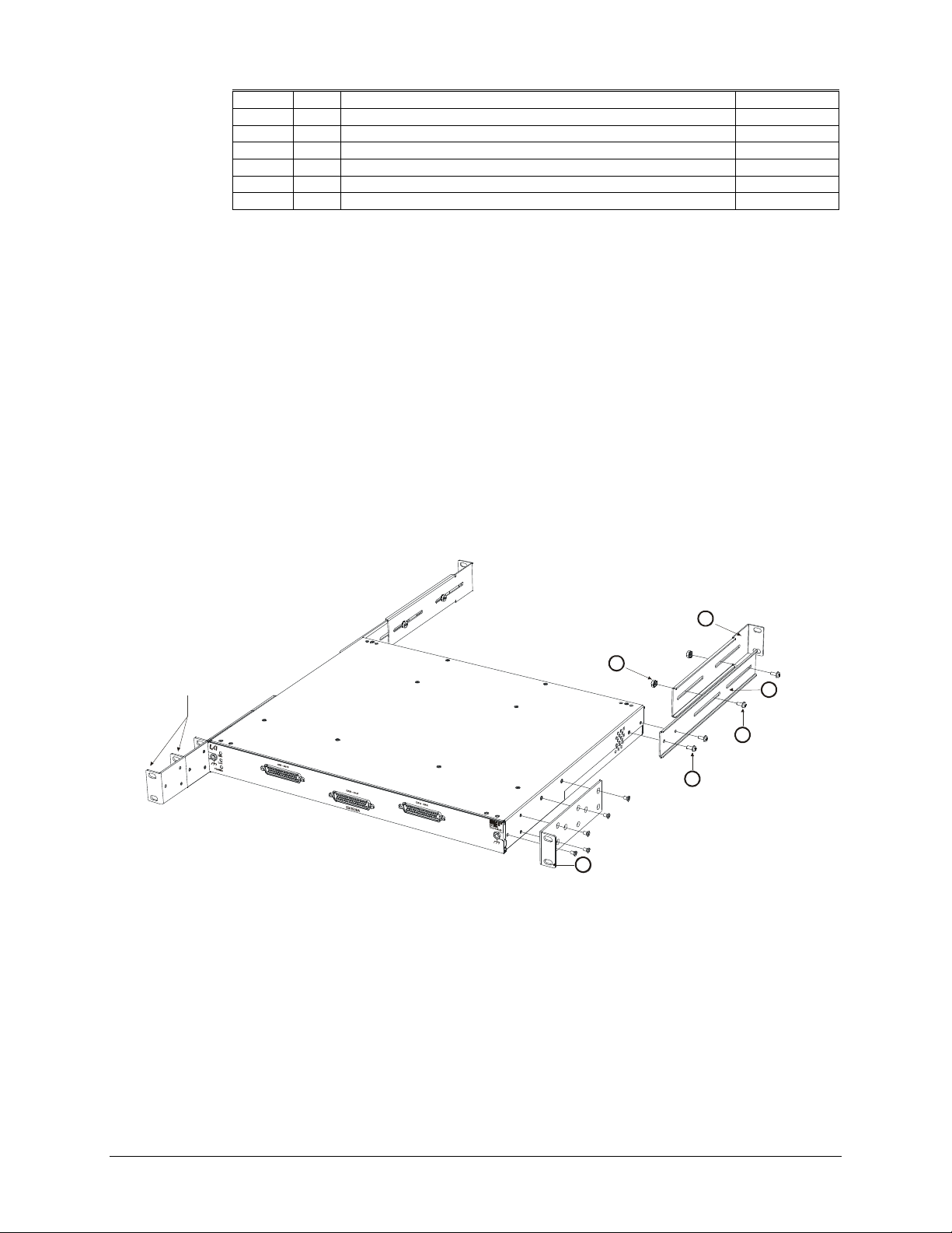
www.vtiinstruments.com
EX10xxA/EX10xxA-51C/RX10xx Preparation for Use 37
1 2 Rack Ear, EX10XXA
41-0482-009
2 2 Bracket, Unit Support, EX10XXA
41-0482-010
3 2 Bracket, Rear Rack Support, EX10XXA
41-0482-011
4
10
Screw, 6-32 x 3/8”, Flat Head Phillips, 82°, Stainless Steel
37-0173-037
5 2 Screw, 6-32 x 3/8” Pan Head Phillips, Sq Cone SEMS Zinc
37-0028-037
6 6 Screw, 8-32 x 3/8” Pan Head Phillips, Sq Cone SEMS Zinc
37-0073-037
7 4 Nut, Hex, KEPS, 8-32 Steel/Zinc
37-0200-832
Assembly Procedure
1) Place the chassis on a protected work surface with its input connectors facing front.
2) Using a #2 Phillips screwdriver, install the rack ears (P/N: 41-0482-009) on the front of the
EX10xxA using five (5) 6-32 X 3/8” flat head Phillips stainless steel screws (P/N: 37-0173-
037) for each rack ear. Note that the “Optional Mounting Locations” in Figure 2-1 allow the
EX10xxA to be installed in a rack either flush or recessed.
3) Next, attach the unit support brackets (P/N: 41-0482-010) to the EX10xxA using two (2) 6-32
x 3/8” pan head Phillips SEMS screws (P/N: 37-0028-037) for each bracket (see Figure 2-1).
4) Place the rear rack support brackets (P/N: 41-0482-011) on the inside of the unit support
brackets installed in step 3 and loosely secure them using two (2) 8-32 x 3/8” pan head Phillips
SEMS screws (P/N: 37-0073-037) and two (2) KEPS hex nuts (P/N: 37-0200-832). Loosely
installing the hardware will allow the rear support bracket to adjust to the proper length once
installed in a rack.
5) Place the EX10xxA in the desired rack slot and secure the front rack ears with hardware
provided with the rack. Once the front bracket are secured, slide the rear support brackets so
that they can be attached to the rack as well. After securing the rear support brackets, tighten
the screws and KEPS nuts installed in step 4.
OPTIONAL MOUNTING LOCATIONS
151x Per Side
2x Per Side
6 2x Per Side
2
1x Per Side
72x Per Side
31x Per Side
FIGURE 2-1: RACKMOUNT HARDWARE INSTALLATION DIAGRAM
Page 38
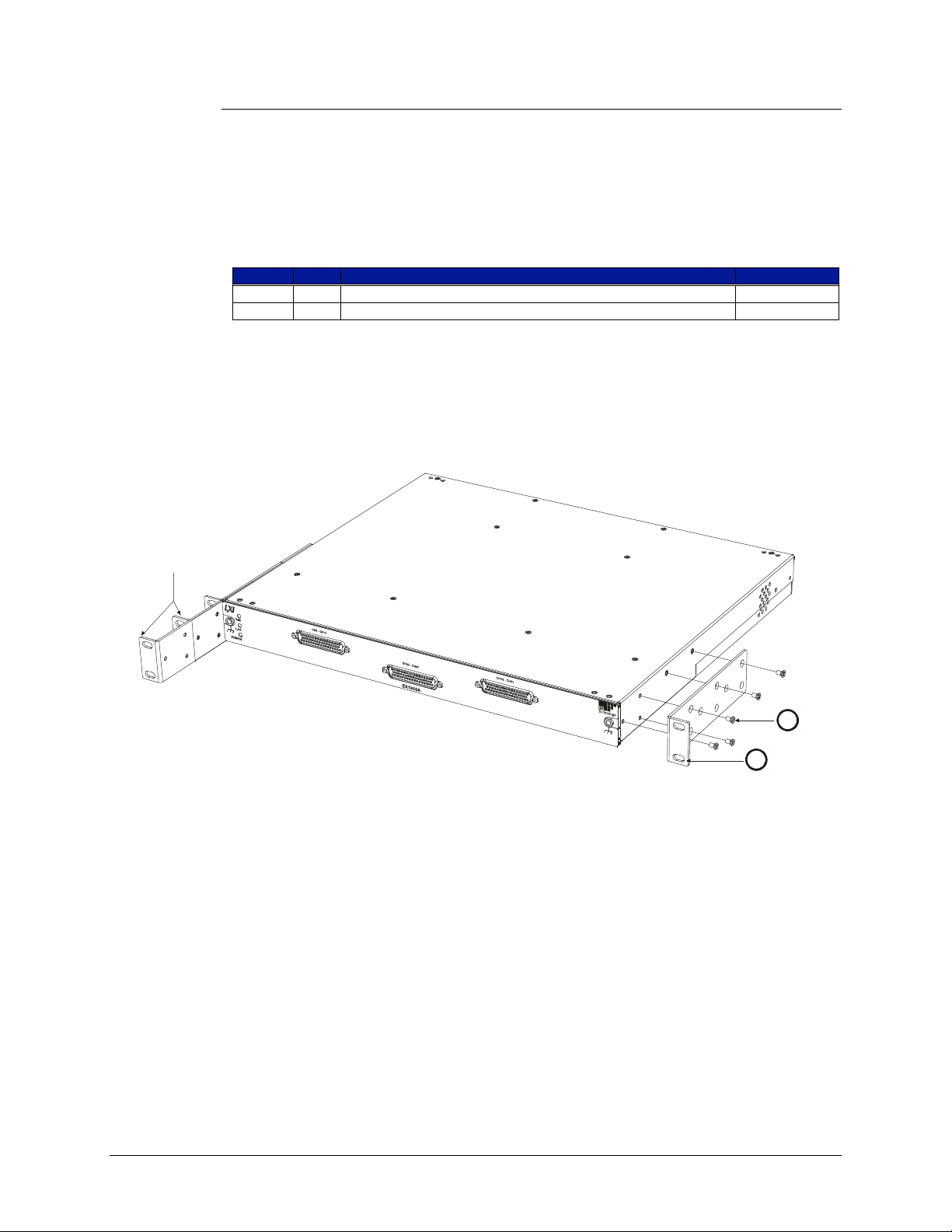
VTI Instruments Corp.
38 EX10xxA Preparation for Use
Rack Ear Installation Option
The rackmount installation option includes all the parts necessary to mount the EX10xxA to the
front of a standard test rack.
Required Tools
1) #2 Phillips screwdriver
Parts List
Item#
Qty
Description
VTI P/N
1 2 Rack Ear, EX10XXA
41-0482-009
2
10
Screw, 6-32 x 3/8", Flat Head Phillips, 82°, Stainless Steel
37-0173-037
Assembly Procedure
1) Place the chassis on a protected work surface with its input connectors facing front.
2) Using a #2 Phillips screwdriver, install the rack ears (P/N: 41-0482-009) on the front of the
EX10xxA using five (5) 6-32 x 3/8” flat head Phillips stainless steel screws (P/N: 37-0173-037)
for each rack ear. Note that the “Optional Mounting Locations” in Figure 2-2 allow the
EX10xxA to be installed in a rack either flush or recessed.
OPTIONAL MOUNTING LOCATIONS
1 1x Per Side
2 5x Per Side
FIGURE 2-2: RACK EAR INSTALLATION DIAGRAM
Page 39
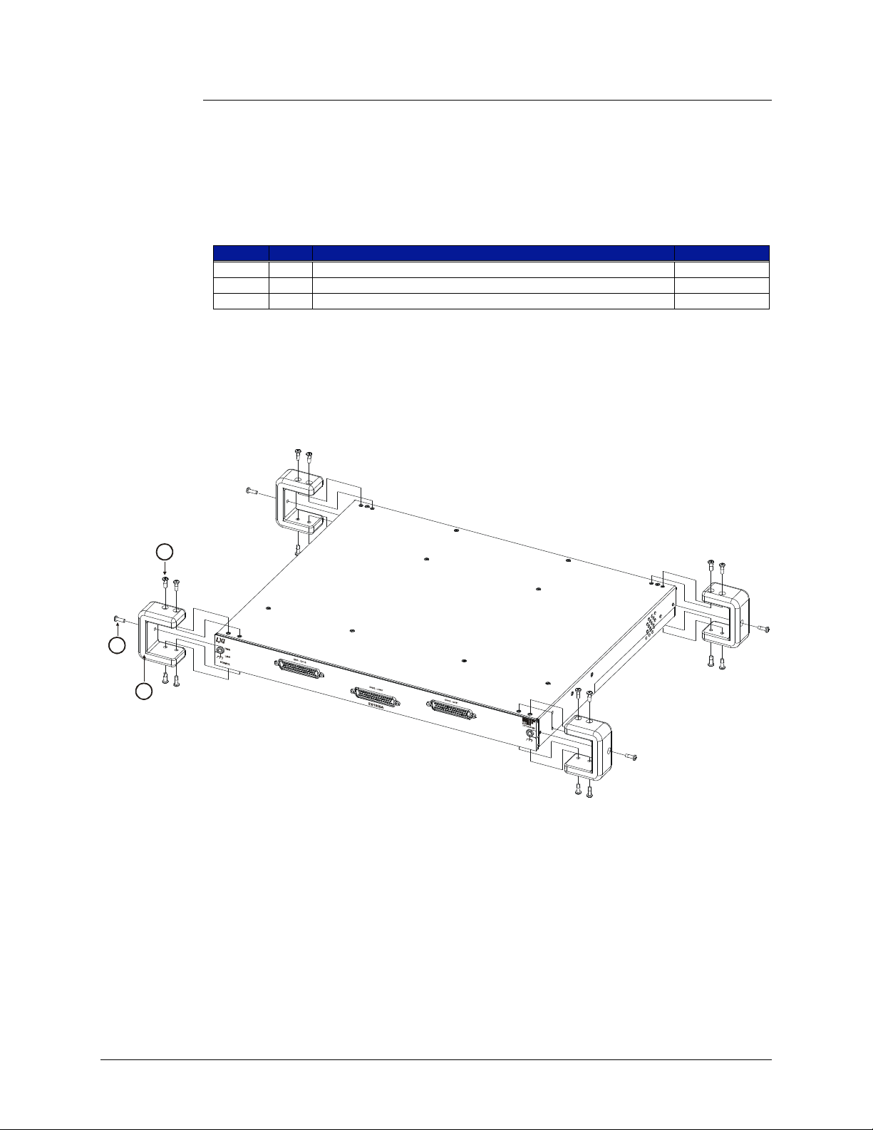
www.vtiinstruments.com
EX10xxA/EX10xxA-51C/RX10xx Preparation for Use 39
Tabletop Installation Option
The tabletop installation option can be used when the EX10xxA is will not be installed in a rack,
but will be employed as a bench top or desktop instrument.
Required Tools
1) #2 Phillips screwdriver
Parts List
Item#
Qty
Description
VTI P/N
1
16
Screw, 6-32 x 7/16”, Pan Head Phillips, Zinc
37-0044-044
2 4 Screw, 6-32 x 1/2”, Pan Head Phillips, Zinc
37-0044-050
3 4 Feet, Corner, Rubber, “U” Shaped
37-0281-201
Assembly Procedure
1) Place the chassis on a protected work surface with its input connectors facing front.
2) Using Figure 2-3, locate the installation locations for each rubber foot.
3) Using the #2 Phillips screw driver, install the four rubber feet using four (4) 6-32 x 7/16” pan
head Phillips screws to secure the top and bottom and one (1) 6-32 x 1/2” pan head Phillips
screw to secure side of each foot.
14x
2
1 Per Item
4 Total
3
4 Per Item
16 Total
FIGURE 2-3: TABLE TOP FEET INSTALLATION DIAGRAM
Page 40
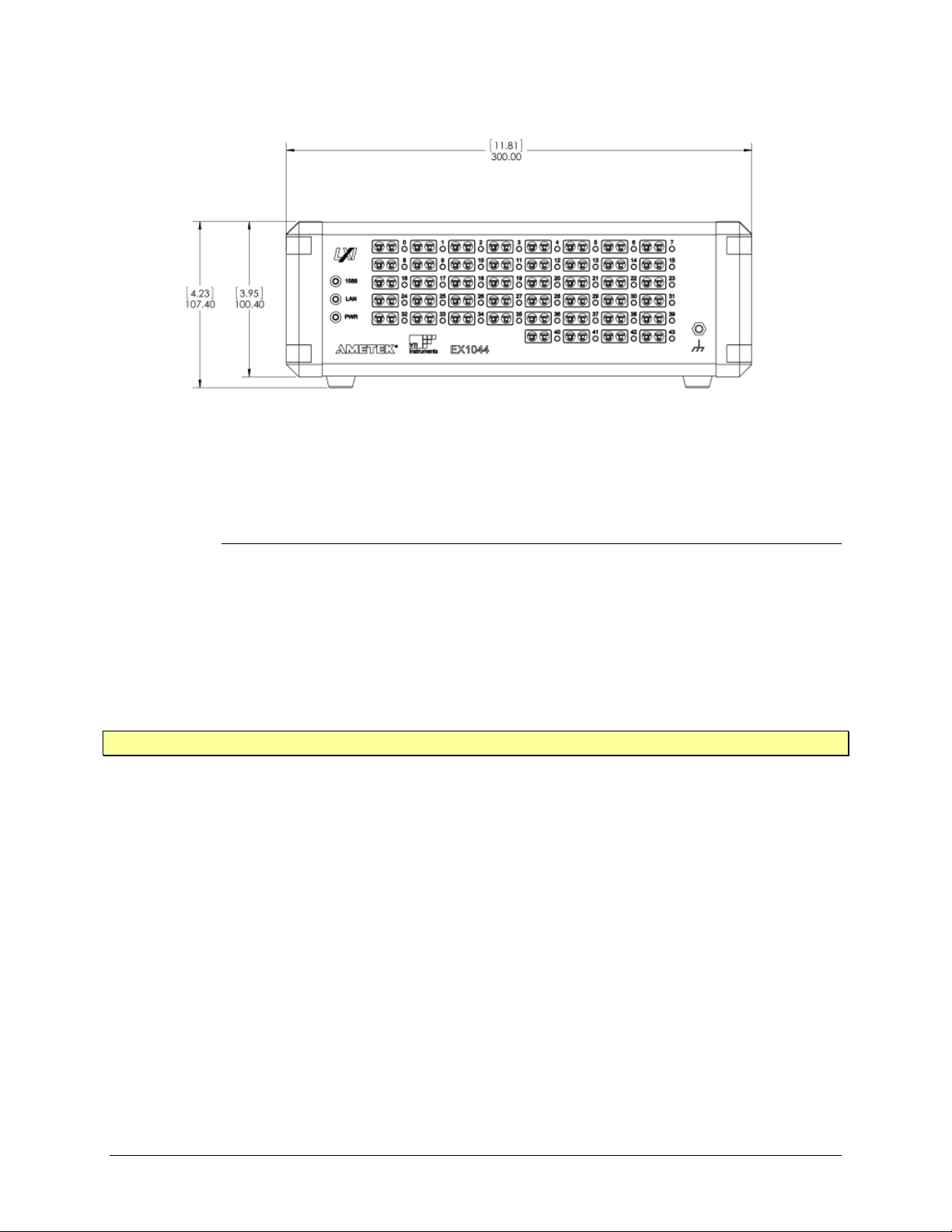
VTI Instruments Corp.
40 EX10xxA Preparation for Use
FIGURE 2-4: EX1044 TABLE TOP USAGE
Installation Option of RX10xx
Mechanical Accessories
1) Power Connector: 27-0673-315, CONN, MIL-C-26482-1, CABLE PLUG, SIZE 14, 15 WAY,
SOCKET
2) Ethernet Connector: 27-0926-008I, CONN, IP67, RJ-45, PL, 8POS, ST
3) Mounting Angle Bracket: 41-0604-012 (2 ea)
4) Screw, M6X10mm: 37-1901-010 (6 ea)
5) Cable Mount Bracket: 41-0604-013 (2 ea)
6) Screw, M3X6mm: 37-0223-006 (4 ea)
NOTE: Mechanical accessories need to order separately
Assembly Procedure
7) Mount option-I: 6X M6 tapped holes are provided at the bottom of the chassis as per Figure 2-3-1
for fixing on horizontal plate or with vibration mount.
8) Mount option-II: The System using Left and Right angle plates provided in the chassis.
9) Mount the unit to the protected area with mounting details provided as per Figure 2-3-1
10) Hole size in the mounting angle bracket is 6.5 mm (dia). Use 6 X M6 X 10mm LG, CAP FLANGE
HD, 10.9 STEEL SCREWS
Page 41
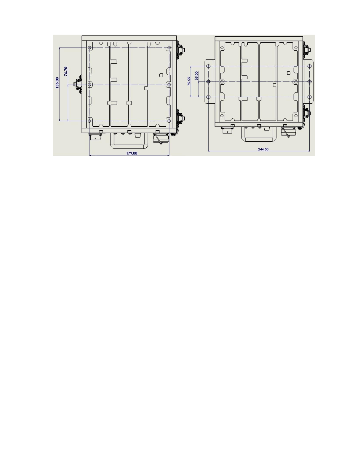
www.vtiinstruments.com
EX10xxA/EX10xxA-51C/RX10xx Preparation for Use 41
FIGURE 2-3-1: RX10XX CHASSIS MOUNTING DETAILS
11) Remove the Top Cover by opening 3 Latches on right and left side of chassis.
Page 42
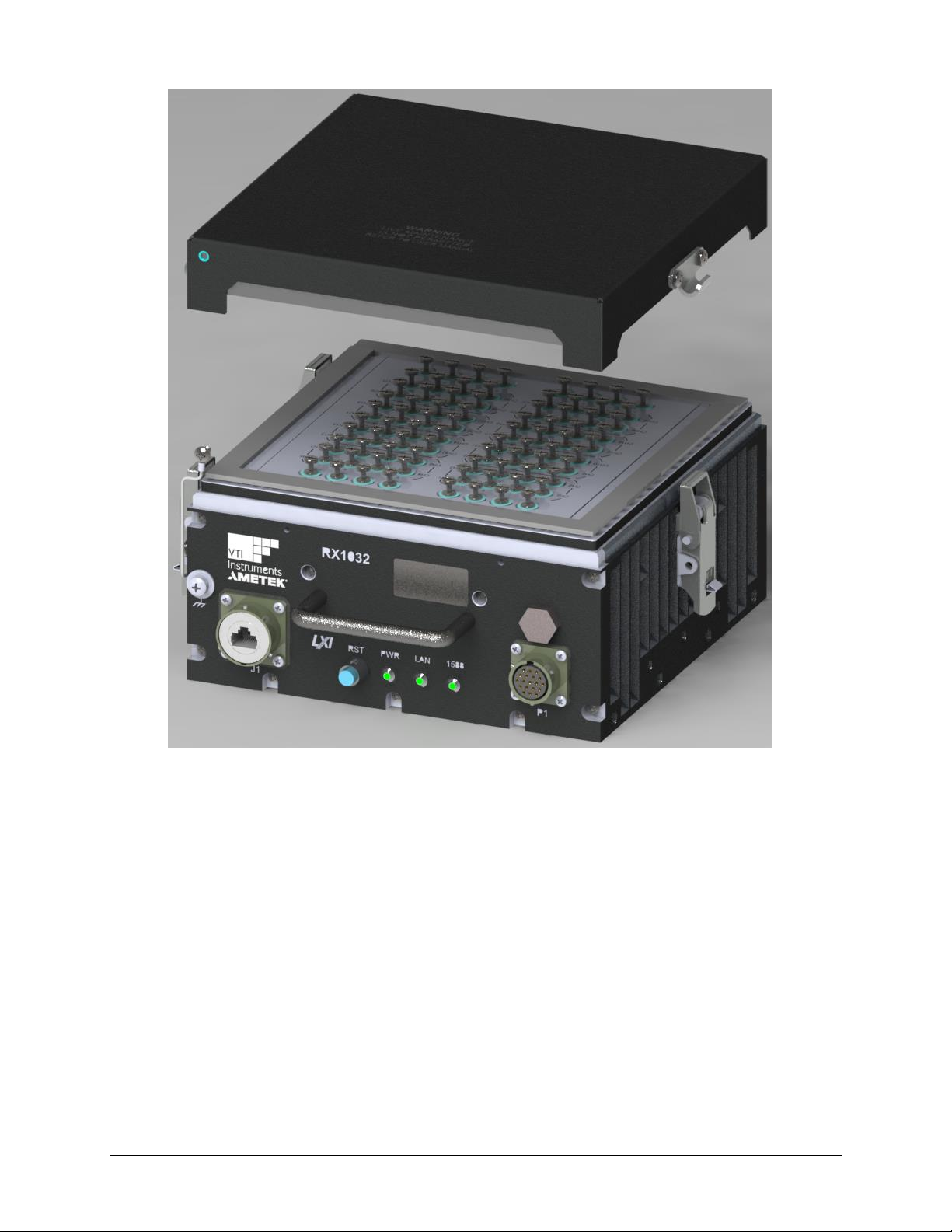
VTI Instruments Corp.
42 EX10xxA Preparation for Use
FIGURE 2-3-2: RX10XX CHANNEL SCREW TERMINAL PLATE VIEW
12) Unscrew the captive screws to inserts the thermocouple wires/ U - Lugs into it.
13) Fix the thermocouple 'U' Lugs into screw terminals. Each channel has S,+ & - signals screws (‘S’
for Shield, ‘+’ for Positive input, ‘-‘ for Negative input). Refer the below channel layout diagram of
screw terminals.
Page 43
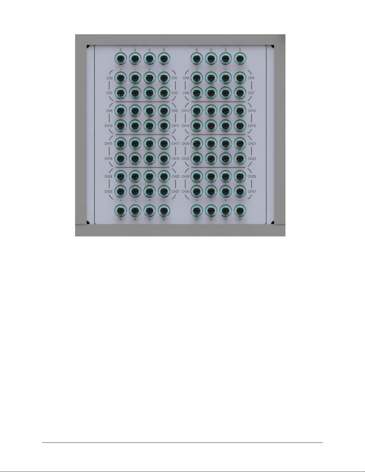
www.vtiinstruments.com
EX10xxA/EX10xxA-51C/RX10xx Preparation for Use 43
FIGURE 2-3-3: RX10XX CJC PLATE TOP VIEW DETAILS
14) Connect RJ45 Ethernet cable connector to J1 connector and other end to PC
15) Prepare P1 mating connector cable loom as per the "RX10xx Connections" Section
16) Connect P1 mating connector cable loom and other end +28V_IN and +28V_RET signals into
28V DC power supply. Power Supply should be capable of produce 2Amps min.
17) Power ON the supply.
18) Wait for 2min time to system boot.
19) Run the SFP application software and configure the channel as per requirement.
20) Wait for warm up time as mentioned in "WARMUP TIME" section
21) Start acquire the channel data
WARM-UP TIME
The specified warm-up time of the EX10xxA/EX10xxA-51C/RX10xx/EX1044 is 60 minutes. If,
however, the unit is being subjected to an ambient temperature change greater than 5 ºC, extra
stabilization time is recommended to achieve maximum performance.
SOFTWARE INSTALLATION
The fastest way to begin controlling an EX10xxA/EX10xxA-51C/RX10xx/EX1044 is to discover
the unit using VTI’s LAN Instrument Connection and Upgrade (or LInC-U) utility. To do this, the
following is required:
A PC or laptop computer
Page 44

VTI Instruments Corp.
44 EX10xxA Preparation for Use
A Microsoft™ Windows™ XP OS with Service Pack 2 (SP2) and Internet Explorer™ (IE)
An Internet connection
VTI’s LInC-U utility
The LInC-U Utility searches for all LAN-based VTI devices on the network and can be found on
the Distribution CD that shipped with the EX10xxA or may be downloaded from the
VTI Instruments corporate website. This utility leverages Apple’s Bonjour plug-in if it is installed
on the host PC, but, in its absence, uses the VXI-11 discovery protocol. This utility can also be used
to upgrade the EX10xxA’s driver and firmware. For more information on using the LInC-U utility,
please refer to its online Help file. For more information on discovering the EX10xxA, please refer
to Web Page Operation in Section 4.
LInC-U Installation
To install LInC-U as a discovery tool for the EX7000’s embedded webpage, insert the
VTI Instruments Corp. Drivers and Product Manuals CD into the host PCs CD-ROM and, using
Windows Explorer, navigate to the <CD-ROM Drive>:\EX Platforms Requisites directory. Next,
run the VTI_LInC-U_setup.exe program. Once installation begins, simply follow the on-screen
instructions.
NETWORK CONFIGURATION
By default, the EX10xxA/EX10xxA-51C/RX10xx/EX1044 will attempt to locate a DHCP server.
If one is found, the IP address assigned by the DHCP server will be assumed. Otherwise, after a
timeout of 20 seconds, the unit will attempt to obtain an IP address by using Auto IP.
Auto IP is a mechanism for finding an unused IP address in the range 169.254.X.Y where X is in
the range 1 - 254 and Y is in the range 0 - 255. The device will first attempt to obtain the specific
address 169.254.X.Y, where X and Y are the second-to-last and last octets of the device’s MAC
address. However, X will be set to 1 if it is 0 in the MAC address, and to 254 if it is 255 in the MAC
address. If this address is already in use, the unit will attempt to obtain other IP addresses in a
pseudorandom fashion until it finds one that is available.
To illustrate the Auto IP mechanism, Table 2-1 lists the Auto IP default address for some example
MAC addresses.
MAC Address
Auto IP Default Address
00:0D:3F:01:00:01
169.254.1.1
00:0D:3F:01:01:01
169.254.1.1
00:0D:3F:01:A3:28
169.254.163.40
00:0D:3F:01:FE:FE
169.254.254.254
00:0D:3F:01:FF:FE
169.254.254.254
TABLE 2-1: AUTO IP DEFAULT ADDRESS ASSIGNMENT
If a static IP address assignment is preferred, one can be optionally assigned via the embedded web
page interface. This is done by clicking the Network Configuration link, disabling DHCP, and
then assigning a static IP address. For more information, see Network Configuration in Section 4.
However, a much more convenient and recommended way to obtain the benefits of a static IP
address is to employ DHCP, but assign the instrument a reserved IP address in your company’s
DHCP server configuration. This reserved address, linked to the EX10xxA’s MAC address on the
DHCP server, would be assigned to the EX10xxA at power up initialization without having to
manually set it on the EX10xxA. The DHCP server configuration provides a centralized, controlled
database of assigned IP addresses, preventing accidental assignment of the same IP address to
multiple instruments. Consult your company’s Information Technology department for assistance.
Page 45

www.vtiinstruments.com
EX10xxA/EX10xxA-51C/RX10xx Preparation for Use 45
VXI-11 Device Discovery is also supported by the EX10xxA. This allows all EX1048s on a local
network to be found without knowledge of their MAC address or IP address with the use of a
broadcast message.
Reset button for EX10xxA/EX10xxA-51C
The reset button on the rear panel of the EX10xxA can be used to restore default network settings.
This is useful for recovery from an incorrect or unknown network configuration. To perform a
network reset:
1) Power off the EX10xxA.
2) Press and hold the reset button.
3) Power on the EX10xxA.
4) Continue to hold the reset button for at least 30 seconds.
5) Release the reset button.
The EX10xxA will power up as usual, but will use the default network configuration (DHCP)
instead of its previous settings.
NETWORK TROUBLESHOOTING
If an error occurs when trying to discover the EX10xxA (see Web Page Operation in Section 4 for
more information on discovery), it may be necessary to change the network settings for the
EX10xxA and the host PC. By using the following methodology, most network-related issues can
be resolved:
1) Restore the EX10xxA’s Default Network Settings
2) Determine PCs Network Settings
3) Set the EX10xxA to Auto IP or Set the EX10xxA to Static IP
4) Restore the Host PCs Network Settings
5) Using Multiple Network Cards
Restore the EX10xxA’s Default Network Settings
It may be the case that the EX10xxA is in an unknown network configuration. The EX10xxA can
be returned to its default state by pressing the Reset button located at the rear of the chassis.
1) Power off the EX10xxA.
2) Press and hold the reset button.
3) Power on the EX10xxA.
4) Continue to hold the reset button for at least 30 seconds.
5) Release the reset button.
Determine PCs Network Settings
1) Ensure that all host PC Ethernet connections are made that will be used while controlling the
EX10xxA. If the PC will be connected to a LAN, ensure that the LAN connection is made.
2) From Windows , navigate to Start→Settings→Network Connections.
3) Right click on the connection that will be used to communicate with the EX10xxA, then
select Properties (see Figure 2-4). Some PCs have multiple network connections, so it is
important to make certain that the connection used to communicate with the EX10xxA is
selected.
Page 46
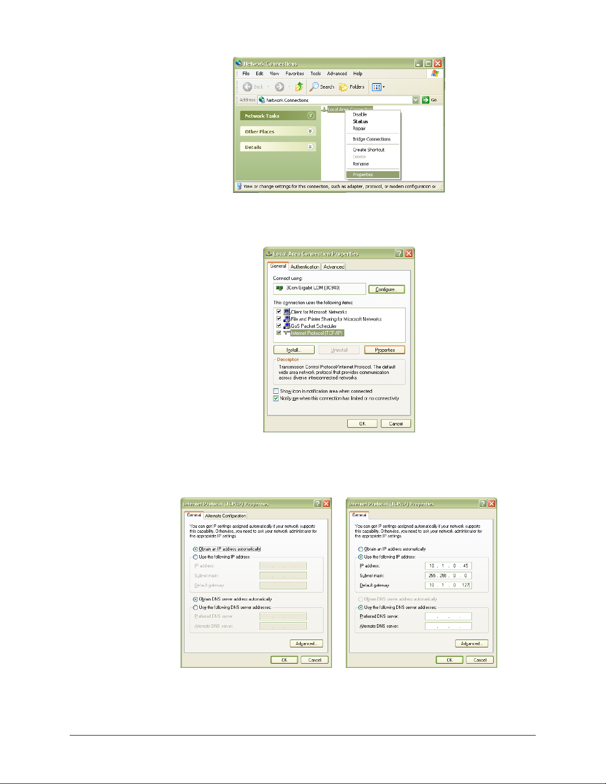
VTI Instruments Corp.
46 EX10xxA Preparation for Use
FIGURE 2-4: NETWORK CONNECTION PROPERTIES
4) Select Internet Protocol (TCP/IP), then click the Properties button as shown in Figure 2-5.
FIGURE 2-5: LOCAL AREA CONNECTION PROPERTIES DIALOG BOX
5) Determine if the PC is set to use auto or static IP. Figure 2-6 shows examples of both auto and
static IP address configurations.
FIGURE 2-6: DYNAMIC (LEFT) AND STATIC (RIGHT) IP ADDRESS CONFIGURATIONS
Page 47
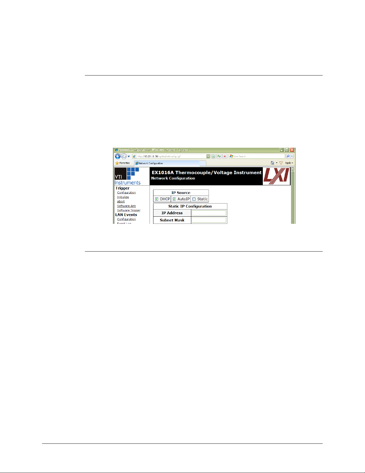
www.vtiinstruments.com
EX10xxA/EX10xxA-51C/RX10xx Preparation for Use 47
6) If set to use a static IP, record the IP address, subnet mask, and default gateway for use later.
Select Obtain an IP address automatically to establish a connection to the EX10xxA. Click
the OK button and proceed to Set the EX10xxA to Static IP. If set to use a dynamic IP, click
the OK button and proceed to Set the EX10xxA to Auto IP.
Set the EX10xxA to Auto IP
1) Remove all network connections from the PC except for the connection to the EX10xxA.
Wireless adapters should be disabled as well.
2) Apply power to the EX10xxA and wait for the LAN LED to turn green.
3) Discover EX10xxA using Bonjour as described in the Web Page Operation in Section 4. The
steps taken previously should ensure that discovery works.
4) Once connected to the EX10xxA, click on Network Configuration in the command menu.
5) Select DHCP and AutoIP in the IP Address Source field and ensure that Static IP is not
selected. Figure 2-7 shows the proper configuration. Click the Submit button to save all
changes.
FIGURE 2-7: EX10XXA SET TO USE AUTO IP
Set the EX10xxA to Static IP
1) Disconnect all network connections from the PC except for the connection between the PC
and the EX10xxA.
2) Apply power to the EX10xxA and wait for the LAN LED to turn green.
3) Discover EX10xxA using Bonjour as described in the Web Page Operation in Section 4. The
steps taken previously should ensure that discovery works.
4) Once connected to the embedded web interface, click on the Network Configuration link in
the command menu.
5) Select the Static checkbox in the IP Address Source field and ensure that DHCP and
AutoIP are not selected.
6) In the IP Address field, enter an appropriate IP address for the EX10xxA. Use the IP address
obtained the Determine PCs Network Settings.
7) step to determine the network address. The network address is the first three digits of the IP
address (10.1.0 in the example provided). The last digit of the IP address (the node), is a
number, 0 through 255, that is not currently assigned to any other device on the network.
Ensure that a unique IP address is assigned to the EX10xxA by consulting a network
administrator.
8) In the Subnet Mask field, enter the subnet mask in the Determine PCs Network Settings
9) step.
10) In the Gateway Address field, enter the same gateway address in the Determine PCs Network
Settings step.
11) Click Submit to save all changes made to the Network Configuration page.
Page 48
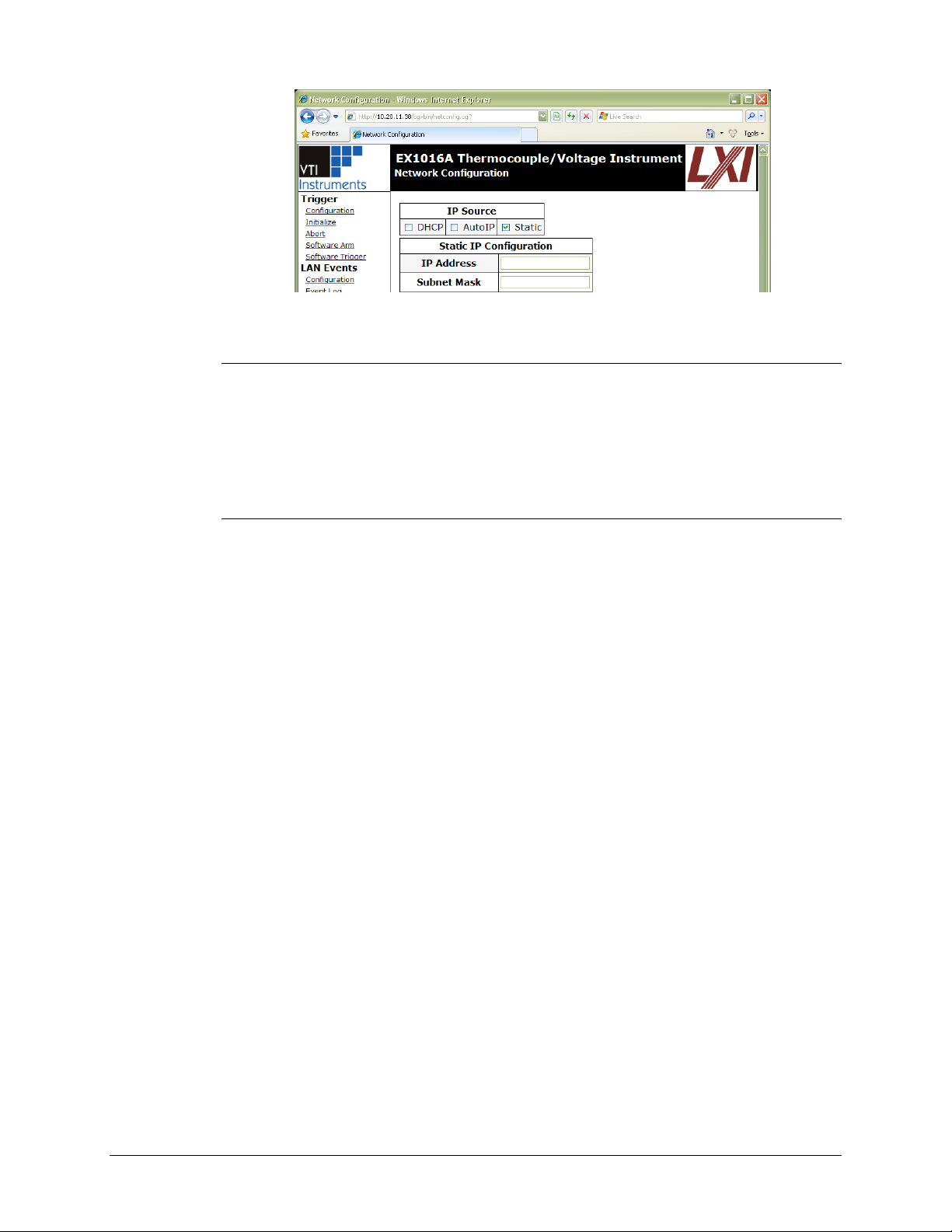
VTI Instruments Corp.
48 EX10xxA Preparation for Use
FIGURE 2-8: EX10XXA SET TO USE STATIC IP
Restore the Host PCs Network Settings
1) Power down the EX10xxA and reconnect it to the LAN in its desired location.
2) If the PC was originally set to use a static IP address, use the procedure in Determine PCs
Network Settings to change the PCs IP address back to its original state.
3) Power on the EX10xxA and wait for the LAN LED to turn solid green.
4) Discover the EX10xxA using VTI’s LInC-U as described in Web Page Operation in
Section 4.
Using Multiple Network Cards
When multiple network cards exist in a single PC, it may be necessary to define a static IP address
to both the host PC NIC card that will interface with the EX10xxA mainframe as well as the
EX10xxA itself. This process is only necessary if a DCHP server is not connected to the network to
which the device is connected and typically occurs when the NIC is connected directly to the
instrument.
The following process can be used to ensure proper functionality.
1) Navigate to Start → Settings → Network Connections.
Disable all network interfaces except the one that is connected to the EX10xxA
mainframe. This is done by right clicking on the interface, then selecting Disable.
Open the web page of the EX10xxA mainframe.
Click the IP Configuration link. A prompt may appear to log into the EX10xxA
mainframe.
Unselect DHCP and AutoIP and ensure that Static is selected.
Enter an IP address into the IP Address field. Although any valid network IP address can
be used, 192.168.1.2 is used in this example. For more information on valid IP addresses,
please consult with an IT administrator.
Set the Subnet Mask. For this example, the subnet mask is 255.255.255.0.
Page 49
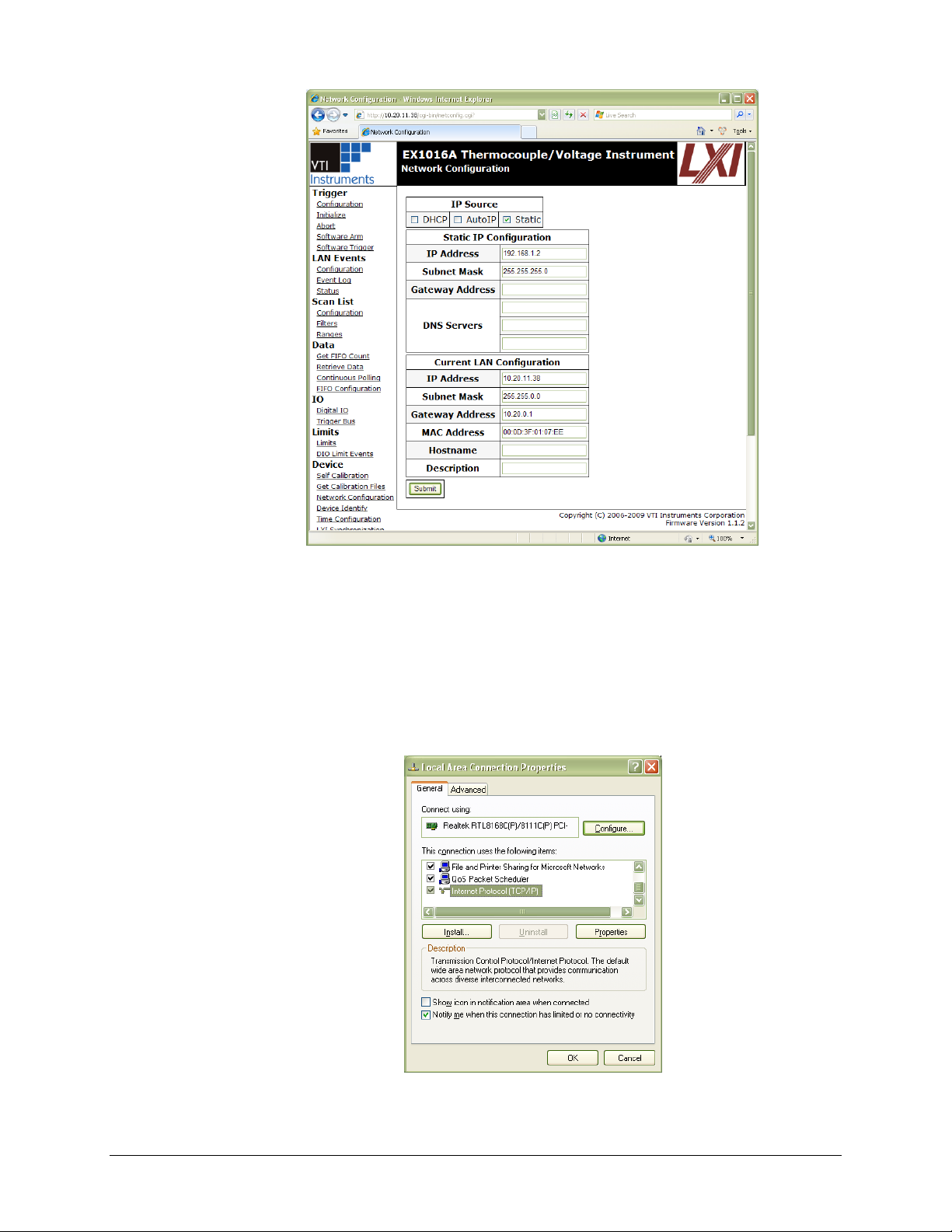
www.vtiinstruments.com
EX10xxA/EX10xxA-51C/RX10xx Preparation for Use 49
FIGURE 2-9: COMPLETED EX10XXA MAINFRAME STATIC IP CONFIGURATION
Click the Submit button. Once this is done, it is no longer possible to communication
with the EX10xxA mainframe. This is normal and is addressed in the following steps.
Set a static IP address for the NIC card by doing the following:
a) Navigate to Start → Settings → Network Connections.
b) Right click on the NIC card that the EX10xxA mainframe is connected to and select
Properties.
c) Select Internet Protocol (TCP/IP) and click Properties.
FIGURE 2-10: TCI/IP SELECTION
Page 50
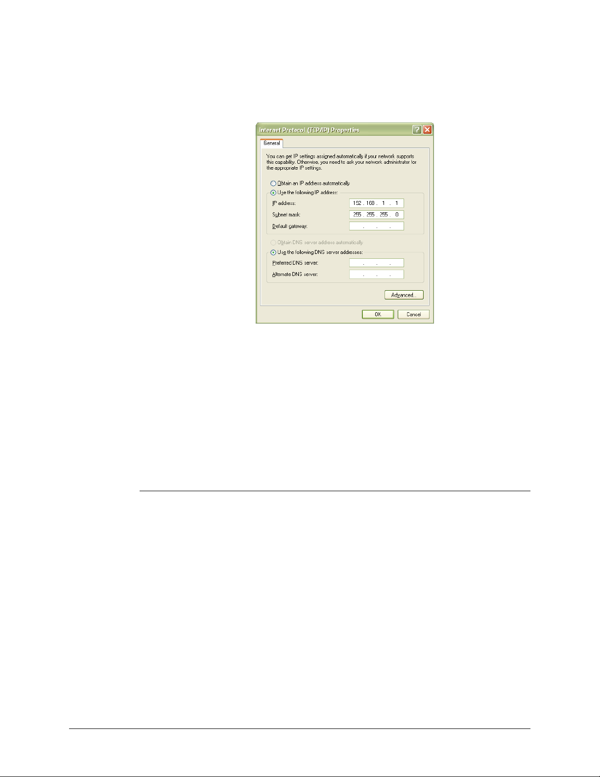
VTI Instruments Corp.
50 EX10xxA Preparation for Use
d) Click the Use the following IP address radio button.
e) Enter the desired IP address. If using the IP from the example above, 192.168.1.1 can be
used.
f) If not automatically completed after the IP address is entered, set the Subnet mask field
to 255.255.255.0.
FIGURE 2-11: COMPLETED NIC STATIC IP CONFIGURATION
g) Click OK to exit the network configuration properties.
TIME CONFIGURATION
The EX10xxA will initially be configured to receive its time through PTP (Precision Time Protocol).
The user can also set time using SNTP (Simple Network Time Protocol) or the time can be set
manually. The manual setting is necessary if the network environment is such that the unit cannot
reach the Internet. For more information, see Time Configuration in Section 4.
INPUT CONNECTIONS / WIRING
Thermocouple Connections
The EX10xxA employs an uncompensated (Cu-Cu) mini-thermocouple female jack as its input
connector. This connector provides a solid, reliable connection that is also easily changeable. Since
it is not thermocouple-type specific, different thermocouple types can be mixed throughout the unit
without hardware modification. The input jack is polarized and will only accept its mating connector
in one orientation. The mating connector is a standard mini-thermocouple male jack. A popular
source is the SMPW series from Omega Engineering. For specified accuracy performance, the input
connector must be of the same thermocouple type as the wire being connected.
Thermocouple wire is polarized, and it is critical to consider this polarity when connecting the
thermocouple wire to the thermocouple jack. For reference, the color designations and polarizations
of the most popular thermocouple types are listed in Table 2-2 for both ANSI (American) and IEC
(European) standards.
Page 51
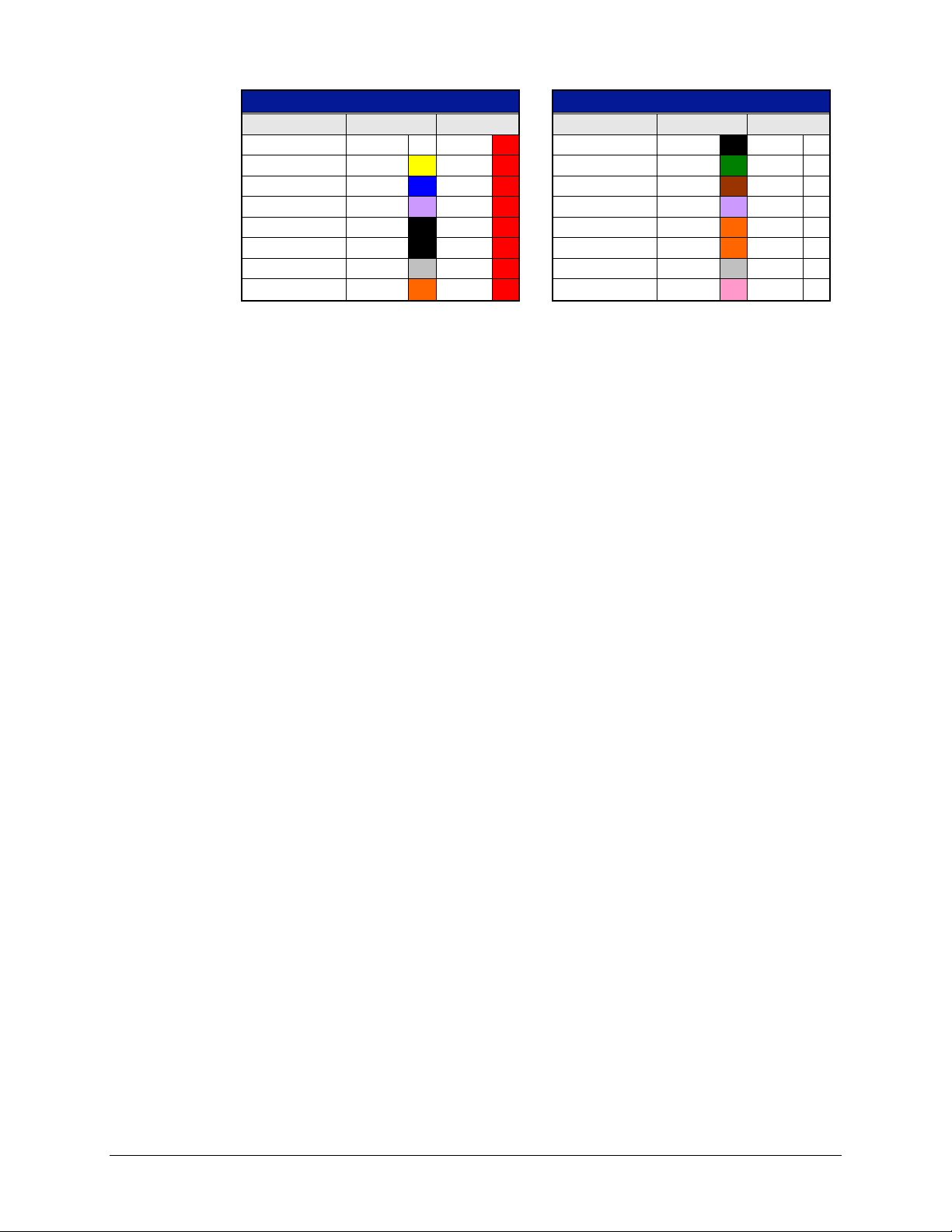
www.vtiinstruments.com
EX10xxA/EX10xxA-51C/RX10xx Preparation for Use 51
ANSI Thermocouple Standard
IEC Thermocouple Standard
Thermocouple
+
-
Thermocouple
+
-
Type J
White
Red
Type J
Black
White Type K
Yellow
Red
Type K
Green
White Type T
Blue
Red
Type T
Brown
White Type E
Violet
Red
Type E
Violet
White
Type S
Black
Red
Type S
Orange
White
Type R
Black
Red
Type R
Orange
White
Type B
Gray
Red
Type B
Gray
White
Type N
Orange
Red
Type N
Pink
White
TABLE 2-2: STANDARD THERMOCOUPLE REFERENCE DESIGNATIONS
In most applications, the length and gauge of the thermocouple wire do not affect the accuracy of
the measurement. Due to the high input impedance and lack of dynamic switching in the signal
conditioning circuitry of the EX10xxA, the resistance and capacitance of the thermocouple wire are
normally not important factors. If, however, maximum system accuracy is desired, the resistance of
the thermocouple wire must be considered as a system error source. As an example, 650 ft of
24 gauge type T wire has a resistance of about 500 Ω. Against the EX10xxA’s typical input bias
current of 7.5 nA, this creates a voltage error of:
V 3.75nA 7.5Ω 500
To convert this error to its representative temperature error, it is then divided by the slope of the
thermocouple characteristic at the temperature of interest. For example, the slope of the type T
characteristic at 0 ºC is 39 µV/ºC. The error at this point is then:
C 0.1CV/ 39V 3.75
This example demonstrates how to evaluate the potential error that a specific wire installation
represents. The user is encouraged to evaluate each individual application to ensure that the error is
within acceptable bounds. In general, best results will be achieved with the shortest and largest wire
that the physical requirements of the application can support.
The EX10xxA offers excellent noise rejection through its high common mode rejection and
selectable bandwidth limiting, which allows for high integrity, noise-free measurements with even
less-than-ideal wiring setups. However, some common instrumentation wiring practices can be used
to achieve or ensure maximum performance.
Shielded thermocouple wire can be used to raise the system’s rejection of electrical interference.
Shielded wire encloses the two thermocouple wires with a low impedance conductor that should be
terminated by the user to a convenient earth ground. The EX10xxA provides an external ground
stud that can be used for this purpose, but any earth ground point is acceptable.
Magnetic interference, which is present wherever high currents are flowing, is conversely decreased
by minimizing the loop area represented by the two thermocouple wires. That is, the wires should
be run closely together from the thermocouple junction to the connections in the thermocouple jack.
Fortunately, most thermocouple wire comes with a sheath that covers the two thermocouple
conductors, inherently creating a small loop area.
Many test applications involve the monitoring of a test article in a chamber, requiring the routing of
numerous types of signals through the chamber’s cable access ports. It is recommended that the
thermocouple wires be run through a separate port and conduit from cables carrying power or high
frequency signals.
Page 52
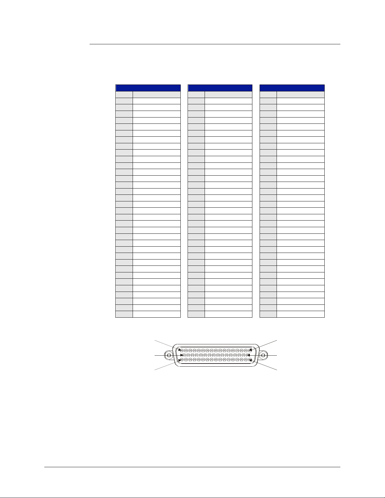
VTI Instruments Corp.
52 EX10xxA Preparation for Use
Voltage Connections
The EX1000A, EX1016A and EX1032A have 50-pin D-sub receptacles for the voltage input
channels. These channels are differential inputs and are mapped as pairs (see Table 2-3). The center
row of each 50-pin D-sub is connected to chassis GND. This allows for optimized shield termination
when using shielded pair wiring.
P1 Connector
P2 Connector
P3 Connector
Pin
Signal
Pin
Signal
Pin
Signal
1
CJC0_RETURN
1 CJC4_RETURN
1 CJC8_RETURN
2
CH07-HI
2 CH23-HI
2 CH39-HI
3
CH07-LO
3 CH23-LO
3 CH39-LO
4
CH06-HI
4 CH22-HI
4 CH38-HI
5
CH06-LO
5 CH22-LO
5 CH38-LO
6
CH05-HI
6 CH21-HI
6 CH37-HI
7
CH05-LO
7 CH21-LO
7 CH37-LO
8
CH04-HI
8 CH20-HI
8 CH36-HI
9
CH04-LO
9 CH20-LO
9 CH36-LO
10
CH03-HI
10
CH19-HI
10
CH35-HI
11
CH03-LO
11
CH19-LO
11
CH35-LO
12
CH02-HI
12
CH18-HI
12
CH34-HI
13
CH02-LO
13
CH18-LO
13
CH34-LO
14
CH01-HI
14
CH17-HI
14
CH33-HI
15
CH01-LO
15
CH17-LO
15
CH33-LO
16
CH00-HI
16
CH16-HI
16
CH32-HI
17
CH00-LO
17
CH16-LO
17
CH32-LO
34
CJC0_INPUT
34
CJC4_INPUT
34
CJC8_INPUT
35
CH15-LO
35
CH31-LO
35
CH47-LO
36
CH15-HI
36
CH31-HI
36
CH47-HI
37
CH14-LO
37
CH30-LO
37
CH46-LO
38
CH14-HI
38
CH30-HI
38
CH46-HI
39
CH13-LO
39
CH29-LO
39
CH45-LO
40
CH13-HI
40
CH29-HI
40
CH45-HI
41
CH12-LO
41
CH28-LO
41
CH44-LO
42
CH12-HI
42
CH28-HI
42
CH44-HI
43
CH11-LO
43
CH27-LO
43
CH43-LO
44
CH11-HI
44
CH27-HI
44
CH43-HI
45
CH10-LO
45
CH26-LO
45
CH42-LO
46
CH10-HI
46
CH26-HI
46
CH42-HI
47
CH09-LO
47
CH25-LO
47
CH41-LO
48
CH09-HI
48
CH25-HI
48
CH41-HI
49
CH08-LO
49
CH24-LO
49
CH40-LO
50
CH08-HI
50
CH24-HI
50
CH40-HI
TABLE 2-3: VOLTAGE CONNECTOR SIGNAL ASSIGNMENTS
Pin 1
Pin 34
Pin 18
Pin 17
Pin 50
Pin 33
FIGURE 2-12: VOLTAGE CONNECTOR PIN LOCATIONS
Pins 1 and 34 are used for connecting a remote thermistor to the internal signal conditioning circuits.
This is used when an external cold plate is being used for temperature measurement. The
recommended thermistor is U.S. Sensor P/N: PS103J2 or PS103J2-RoHS. This device is 10 kΩ at
25 °C with ±0.1 ºC initial accuracy and the 0 °C to 50 °C BETA is 3890. The thermistor path, within
the EX10xxA product, is single ended and designed to be connected to an electrically isolated
thermistor. The use of a grounded thermistor is not recommended.
Page 53
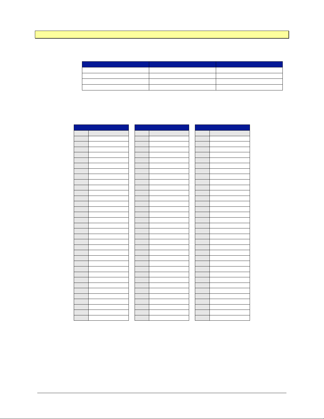
www.vtiinstruments.com
EX10xxA/EX10xxA-51C/RX10xx Preparation for Use 53
NOTE Pins 18 through 33 on P1, P2, and P3 are chassis ground pins.
The mating connector for the EX10xxA is a 50-pin D-sub male connector, and is available from the
following companies:
Manufacturer
Part Number
Description
Conec
163X11159X
Connector
Conec
165X13409XE
Backshell
NorComp
171-050-103L001
Connector
NorComp
977-050-020R121
Backshell
This is only a partial listing as there are many sources for D-sub connectors.
The EX1000A-51C have 50-pin D-sub receptacles for the voltage input channels. These channels
are differential inputs and are mapped as pairs (see Table 2-34).
P1 Connector
P2 Connector
P3 Connector
Pin
Signal
Pin
Signal
Pin
Signal
1
CH48-LO
1 CH49-LO
1 CH50-LO
2
CH07-HI
2 CH23-HI
2 CH39-HI
3
CH07-LO
3 CH23-LO
3 CH39-LO
4
CH06-HI
4 CH22-HI
4 CH38-HI
5
CH06-LO
5 CH22-LO
5 CH38-LO
6
CH05-HI
6 CH21-HI
6 CH37-HI
7
CH05-LO
7 CH21-LO
7 CH37-LO
8
CH04-HI
8 CH20-HI
8 CH36-HI
9
CH04-LO
9 CH20-LO
9 CH36-LO
10
CH03-HI
10
CH19-HI
10
CH35-HI
11
CH03-LO
11
CH19-LO
11
CH35-LO
12
CH02-HI
12
CH18-HI
12
CH34-HI
13
CH02-LO
13
CH18-LO
13
CH34-LO
14
CH01-HI
14
CH17-HI
14
CH33-HI
15
CH01-LO
15
CH17-LO
15
CH33-LO
16
CH00-HI
16
CH16-HI
16
CH32-HI
17
CH00-LO
17
CH16-LO
17
CH32-LO
34
CH48-HI
34
CH49-HI
34
CH50-HI
35
CH15-LO
35
CH31-LO
35
CH47-LO
36
CH15-HI
36
CH31-HI
36
CH47-HI
37
CH14-LO
37
CH30-LO
37
CH46-LO
38
CH14-HI
38
CH30-HI
38
CH46-HI
39
CH13-LO
39
CH29-LO
39
CH45-LO
40
CH13-HI
40
CH29-HI
40
CH45-HI
41
CH12-LO
41
CH28-LO
41
CH44-LO
42
CH12-HI
42
CH28-HI
42
CH44-HI
43
CH11-LO
43
CH27-LO
43
CH43-LO
44
CH11-HI
44
CH27-HI
44
CH43-HI
45
CH10-LO
45
CH26-LO
45
CH42-LO
46
CH10-HI
46
CH26-HI
46
CH42-HI
47
CH09-LO
47
CH25-LO
47
CH41-LO
48
CH09-HI
48
CH25-HI
48
CH41-HI
49
CH08-LO
49
CH24-LO
49
CH40-LO
50
CH08-HI
50
CH24-HI
50
CH40-HI
TABLE 2-4: VOLTAGE CONNECTOR SIGNAL ASSIGNMENTS
The Pin out on the 3 D-sub connectors will provide the connection for additional channels as detailed
below:
a) P1 Connector, Pin 1 and Pin 34 becomes channel 49
b) P2 Connector, Pin 1 and Pin 34 becomes channel 50
c) P3 Connector, Pin 1 and Pin 34 becomes channel 51
Page 54
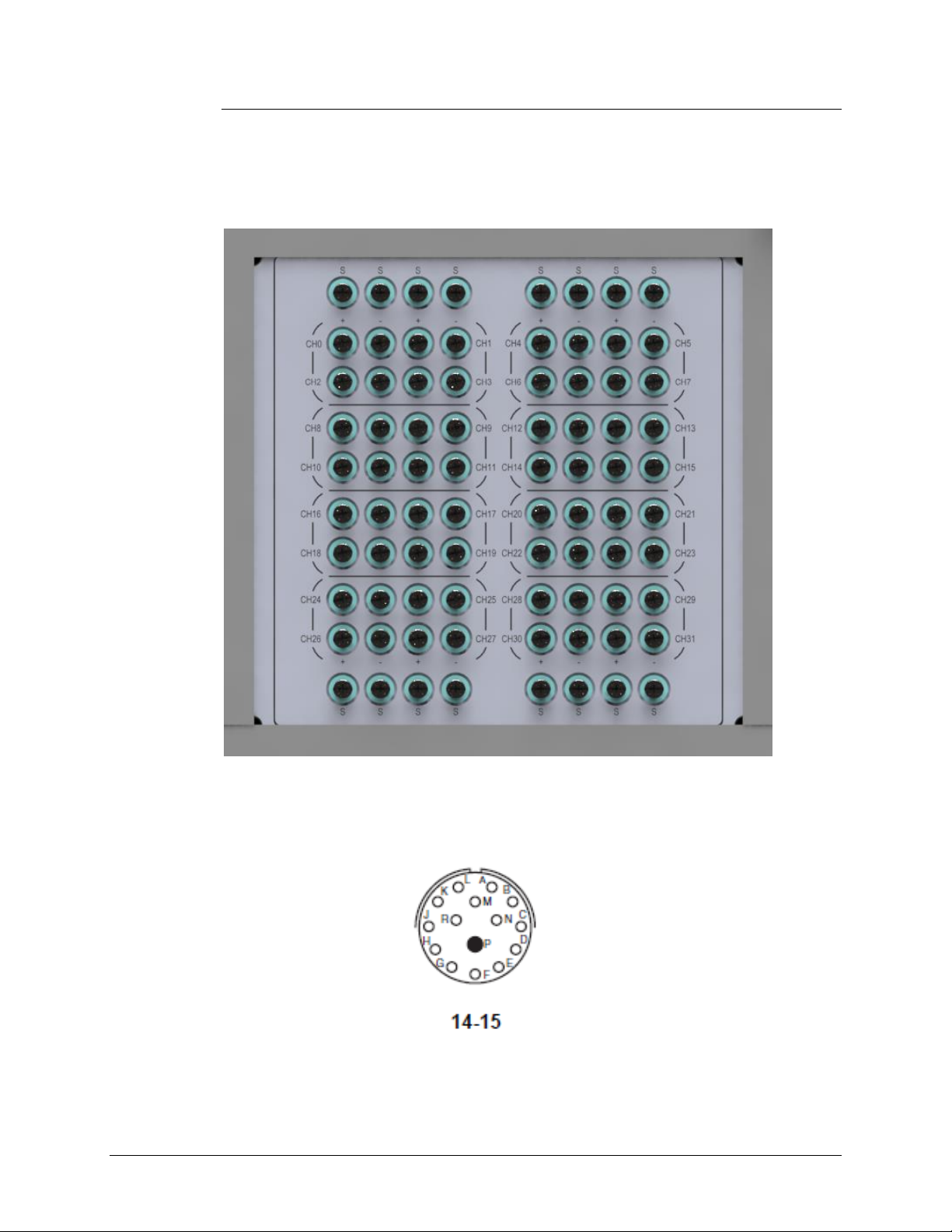
VTI Instruments Corp.
54 EX10xxA Preparation for Use
RX10xx Connections
In RX10xx, the channel wiring is via Screw Terminals and is brought out through a cable gland.
Refer to Figure 2-13.
The Power Lines and the other IO Pins are routed through a 13 Pin Circular Connector (P1), refer
to Figure 2-14 and Table 2-4.
FIGURE 2-13: CHANNEL SCREW TERMINAL PLATE SHOWING 32 CHANNELS ON RX10XX
FIGURE 2-14: 15 PIN CIRCULAR CONNECTOR ON RX10XX (P1)
Page 55
www.vtiinstruments.com
EX10xxA/EX10xxA-51C/RX10xx Preparation for Use 55
TABLE 2-5: 13 PIN CIRCULAR CONNECTOR SIGNAL ASSIGNMENTS IN RX10XX (P1)
NOTE: 22 AWG wire can be used for the P1 connector cable looming
ATTENTION - Important safety instructions for RX10xx input supply
THE FOLLOWING PIN CONNECTION TO BE CAREFULLY CONNECTED WITH EXTERNAL SUPPLY. ANY MISTAKE IN THE
CONNECTION MAY LEAD TO SYSTEM DAMAGE
Pin
Description
Remarks
P1/R
+28V_IN
+28V DC Power Input
P1/P
28V_RET
28V Return DC Power Input
P1/P
28V_RET
28V Return DC Power Input
P1/N
+28V_IN
+28V DC Power Input
P1/A
DMM_HI_OUT
Not to be Used (Factory Calibration Purpose)
P1/L
DMM_LO_OUT
Not to be Used (Factory Calibration Purpose)
P1/B
DAC0_OUT1
Not to be Used (Future Purpose)
P1/K
DAC0_OUT2
Not to be Used (Future Purpose)
P1/C
DAC1_OUT1
Not to be Used (Future Purpose)
P1/J
DAC1_OUT2
Not to be Used (Future Purpose)
P1/M
AGND
Not to be Used (Future Purpose)
P1/D
DIO1
General Purpose Digital I/O
P1/H
DIO2
General Purpose Digital I/O
P1/E
DIO3
General Purpose Digital I/O
P1/G
DIO4
General Purpose Digital I/O
P1/F
DGND
GND for General Purpose DIO
Pin
Description
P1/R
+28V_IN
P1/P
28V_RET
P1/P
28V_RET
P1/N
+28V_IN
Page 56

Page 57
www.vtiinstruments.com
EX10xxA Triggering 57
SECTION 3
BASIC OPERATION
INTRODUCTION
This section expands on the description of the EX10xxA’s / RX10xx’s features and explains how
to best use them.
ENGINEERING UNIT (EU) CONVERSION
Each EX10xxA/RX10xx input channel can be individually configured for one of eleven different
EU conversions. The selections and their definitions are:
Conversion
Parameter
Voltage
mV
Type J
J
Type K
K
Type T
T
Type E
E
Type S
S
Type R
R
Type B
B
Type N
N
User-defined 0
User0
User-defined 1
User1
TABLE 3-1: ENGINEERING UNIT CONVERSION SETTINGS
Voltage The instrument will return the raw voltage measured at its input
with units of volts (V). It is unaffected by the measured or input
CJC temperature for that channel.
Type J, K, T, E, S, R, B, N The instrument will return the compensated thermocouple
temperature measured at its input with units of temperature (ºC or
ºF). The thermocouple calculations are performed using the fullorder polynomial equations and coefficients from the NIST ITS90 Thermocouple Database.
User-defined 0, User-defined 1 The instrument will return the compensated thermocouple
temperature measured at its input with units of temperature (ºC or
ºF). The thermocouple calculations are performed using userdefined coefficients for the polynomial equations. More
information on this is given under User-defined Conversions.
The default selection is voltage.
Page 58

VTI Instruments Corp.
58 EX10xxA Triggering
NOTE In a mixed thermocouple system, it is very easy to accidentally mismatch the hardware setup and
the software configuration setup. Care is especially warranted, as the resultant errors may not be
large enough to obviously indicate a problem, but be significantly larger than the accuracy
specification of the instrument.
Linear Correction
The EX10xxA provides the capability to apply a linear transformation on all measurement data after
EU conversion. Each channel can be programmed with a gain and offset which are applied as
gain*(data-offset).
Gains default to 1.0 and offsets default to 0.0.
VOLTAGE MEASUREMENT RANGES
The EX10xxA provides ±0.067 V and ±0.1 V voltage measurement ranges on thermocouple
channels and voltage channels additionally provide ranges of ±0.01 V, ±1 V, and ±10 V. Voltage
measurement range is programmable on a per-channel basis.
EX10xxA-51C has only option for voltage channels in the following range ±0.01 V, ±1 V, and
±10 V. Voltage measurement range is programmable on a per-channel basis.
The default selection for voltage channels is the ±10 V range, while thermocouple channels default
to a range of ±67 mV.
HARDWARE FILTER
Each EX10xxA input channel can be individually configured with a hardware filter of 4 Hz, 15 Hz,
40 Hz, 100 Hz, 500 Hz, and 1 kHz cutoff frequency. Of the five settings, the 4 Hz setting is suitable
for the majority of temperature measurement applications. It offers sufficient response to pass
medium gauge thermocouple signals without distortion, while providing the highest degree of
(50/60) Hz common mode rejection. This setting also provides the lowest noise floor and is
recommended for all applications that do not require a higher bandwidth. For those that do, however,
the additional filter setting provides that capability. Their response will pass the output from even
the fastest fine-gauge thermocouples with little distortion.
The default selection is 4 Hz.
MEASUREMENT RANGE / INPUT PROTECTION
The specified input voltage range of the EX10xxA thermocouple channels is ±67 mV or ±100 mV
for voltage measurements. This level refers to the maximum differential voltage, or voltage that is
applied between the (+) and (–) input terminals, that can be measured without distortion. The
maximum common mode voltage, or voltage that is applied to the (+) and (–) inputs together, that
can be applied without causing out-of-specification distortion of the differential measurement is
±10 V. Application of voltage beyond these levels will result in incorrect measurements, but no
instrument damage, up to a maximum of ±35 V.
NOTE The application of voltages beyond ±35 V can permanently damage the EX10xxA.
Page 59
www.vtiinstruments.com
EX10xxA Triggering 59
The measurement range of the EX10xxA in terms of temperature is a function of its input voltage
range and the capabilities of the thermocouple sensors themselves. Specifically, the measurement
range of the EX10xxA for the standard thermocouple types is the following:
Type
Min (°C)
Max (°C)
Min (°F)
Max (°F)
J
-200
1200
-328
2192 K -200
1372
-328
2502 T -200
400
-328
752 E -200
900
-328
1652 S -50
1768
-58
3214 R -50
1768
-58
3214 B 250
1820
482
3308 N -200
1300
-328
2372
TABLE 3-2: EX10XXA MEASUREMENT RANGE
In addition to the standard thermocouple types, the EX10xxA can accept and measure a custom
thermocouple of any type. The effective measurement range in temperature is subsequently
determined by the input voltage range of the EX10xxA and the thermocouple transfer function of
the custom thermocouple.
In terms of voltage, the thermocouple connectors may only accept an input voltage of ±67 mV when
performing temperature conversion. When in voltage mode, these connectors can accept either
±0.067 V or ±0.1 V inputs. The voltage connectors may use either ±0.01 V, ±0.067 V, ±0.1 V,
±1.0 V, or ±10.0 V inputs for both EU temperature conversion or voltage measurements. When
temperature is selected, the instrument automatically switches the selected channel(s) to the ±67 mV
range. The EX1000A-TC is a special case where thermocouple inputs are used for voltage
measurement and may utilize all input ranges available to the voltage connectors. Table 1- provides
an overview of each models capabilities.
COLD JUNCTION COMPENSATION (CJC)
For highest accuracy and stability, the EX1000A-TC, EX1016A, EX1032A, EX1048A and RX1032
provide embedded isothermal input sections that are monitored by twelve precision thermistors
(based on Model#, number of thermistors may vary), one for every four thermocouple channels.
(Note, the EX1000A may utilize external thermistors as described in the Voltage Connections
section). To ensure that CJC information is current and time correlated with the input channels, CJC
channels are measured with every scan, providing a maximum time separation of less than 4 ms
between the input channel measurement and its associated CJC measurement. Table 3-3 shows the
association between the CJC and input channels.
CJC #
Channel
Input Channel
CJC0
48
0-3
CJC1
49
4-7
CJC2
50
8-11
CJC3
51
12-15
CJC4
52
16-19
CJC5
53
20-23
CJC6
54
24-27
CJC7
55
28-31
CJC8
56
32-35
CJC9
57
36-39
CJC10
58
40-43
CJC11
59
44-47
TABLE 3-3: CJC CHANNEL / INPUT CHANNEL RELATIONSHIP
Page 60
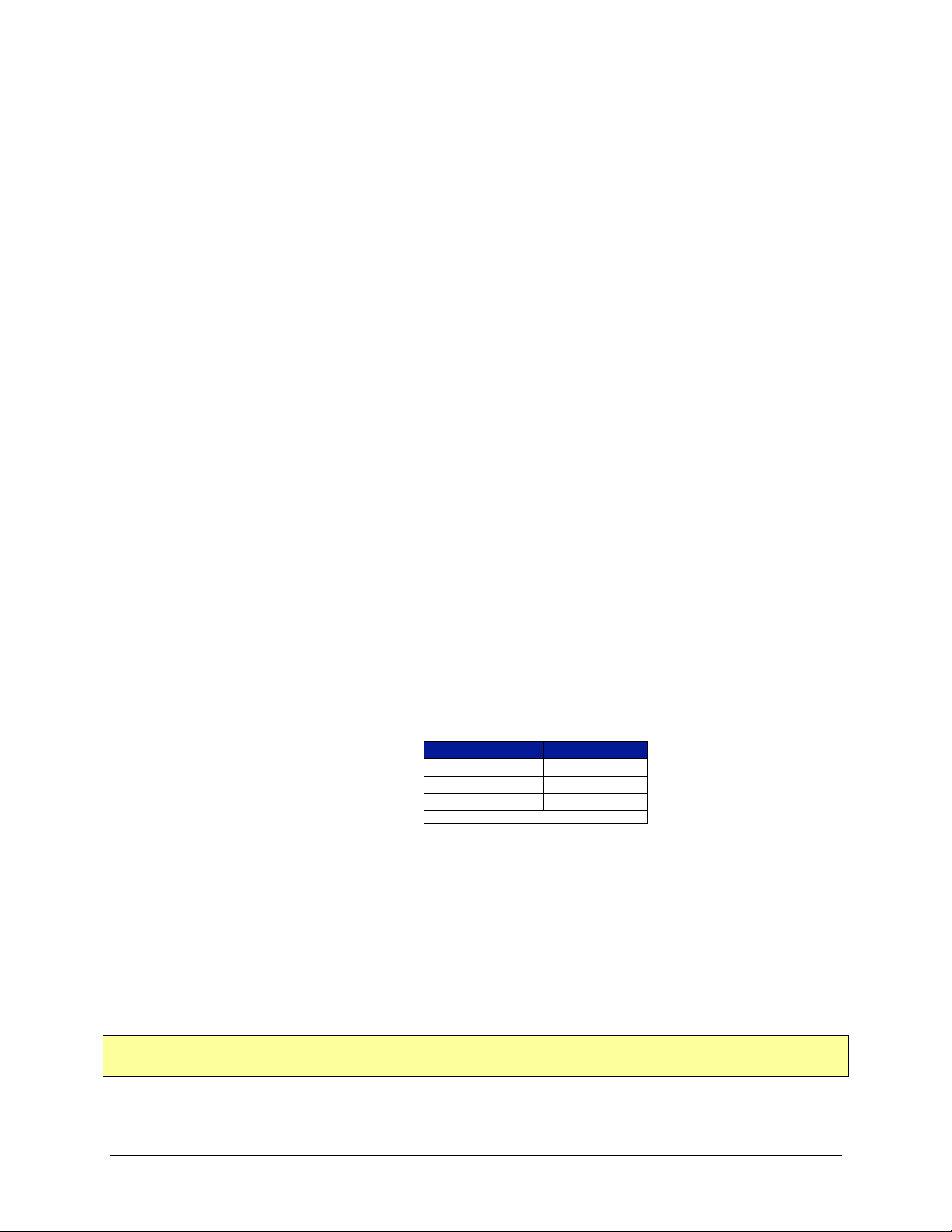
VTI Instruments Corp.
60 EX10xxA Triggering
The user has configuration control over the reporting of the measured CJC data. This control only
affects the display of their data, not the actual measurement of them. They are updated with every
scan, regardless of their reporting status. If they are reported, their values are provided with units of
ºC, unaffected by the °C/°F configuration setting of the input channels.
The EX10xxA also accommodates the use of an external cold junction that is maintained and
measured by the user. In this application, the cold junction temperature in ºC is entered into the
EX10xxA and enabled on a per channel basis. That is, the use of internal and user-defined CJC
inputs can be mixed throughout the unit. This control is unaffected by the °C/°F configuration setting
of the input channels.
The default selections are:
CJC reporting is disabled
User-defined CJC temperatures are 0.0
User-defined CJC temperatures are disabled for all channels
TEMPERATURE UNITS
The EX10xxA can output its temperature data with units of ºC or ºF. This is controlled on a global
basis, such that all input channels are configured with one setting. This selection applies to input
channel data only. CJC measurement data and the input values for external CJC temperatures are
fixed at ºC. Similarly, input channels configured for an EU conversion of voltage are unaffected by
this setting.
The default selection is °C.
SAMPLING RATE / NOISE PERFORMANCE
The EX10xxA can be configured for a sampling rate up to a maximum of 1 kSa/s, regardless of the
number of channels included in the scan list. The selected sampling rate refers to the frequency at
which the entire scan list is measured. As such, all channels are measured at the same sampling rate.
When the requested sampling rate is significantly less than 1 kSa/s, however, the EX10xxA
automatically takes and averages multiple samples. This offers improved noise performance, while
maintaining the requested data output rate. For example, 4096 readings of a K type thermocouple at
25 ºC are displayed with the following typical noise profiles at different selected sampling rates:
Sampling Rate*
Noise (ºCp-p)
≤200 Hz
0.01
500 Hz
0.19
1 kHz
0.37
*4 Hz filter applied
TABLE 3-4: TYPE T THERMOCOUPLE NOISE PROFILE VS. SAMPLING RATE
As implied by Table 3-4, the maximum averaging occurs once the sampling rate reaches 200 Hz
and represents the ultimate noise floor of the instrument. Decreasing the sampling rate further does
not result in a lower noise profile. In practice, the noise performance delivered by the EX10xxA is
a function of the slope of the thermocouple characteristic for the sensor being used. That is, type E
thermocouples (59 µV/ºC) will deliver inherently quieter measurements than type K thermocouples
(39 µV/ºC). However, the relative relationship between noise and sampling rate shown above will
be true for any thermocouple type. Consequently, for best instrument noise performance, the
sampling rate should be set as low as the data collection requirements allow.
NOTE The described averaging mechanism occurs only if the trigger model is configured with a TRIG
source of Timer or LXI alarm. For more details, see Maximizing Measurement Performance.
Page 61
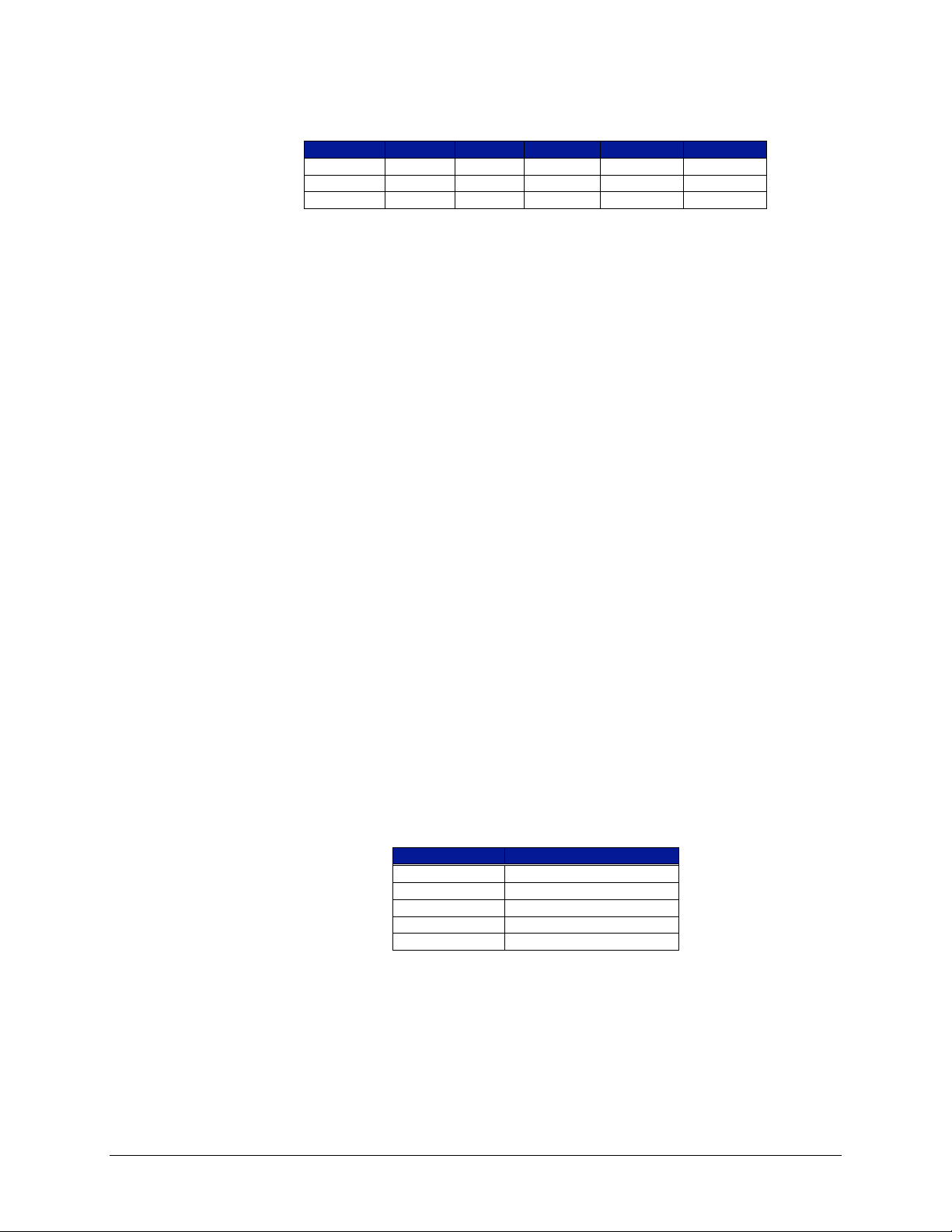
www.vtiinstruments.com
EX10xxA Triggering 61
For voltage channels, similar results are seen. After taking 512 readings at each input voltage at
varying frequencies, the following typical noise profile can be seen.
Scan Rate
±10.0 V
±1.0 V
±0.1 V
±0.067 V
±0.010 V
200 Hz
0.0005
0.00005
0.000005
0.0000035
0.000001
500 Hz
0.0009
0.00009
0.000009
0.000006
0.0000012
1 kHz
0.0019
0.00019
0.000019
0.000013
0.0000019
TABLE 3-5: VOLTAGE MEASUREMENT NOISE PROFILE VS. SAMPLING RATE
SCAN LIST CONFIGURATION
The EX10xxA can be configured to include from 1 to all 48 of its input channels in the scan list and
EX10xxA-51C can be configured to include from 1 to all 51 of its input channels in the scan list.
Because of the channel independence present in the EX10xxA/EX10xxA-51C design, there are no
accuracy, noise, or speed ramifications from the structure of the scan list. Its channel entries can
consequently be solely dictated by the user’s application requirements. A valid scan list consists of:
at least one channel
no more than 48 channels for EX10xxA
no more than 51 channels for EX10xxA-51C
no repeated channels
A scan list entered via the embedded web page interface will be scanned in sequential order from
the lowest to the highest numbered enabled channel. For greater control, channels can be added to
a scan list in any order (although the channels will be scanned in numeric order once the scan list is
executed).
Each EX10xxA input channel maintains its high input impedance and operational independence
from the other channels regardless of its inclusion in the scan list. That is, the connection or lack of
connection to a valid input signal of unscanned channels makes no difference.
SCAN LIST TIMING
Each scan sequence commences with the sequential measurement of the twelve CJC channels for
EX10xxA, regardless of the population of the scan list, the use of external CJC temperatures, or the
EU conversions employed on the input channels. The enabled scan list channels are then
individually measured. In order to provide the tightest time correlation possible between channel
measurements, the scan sequencer cycles through the scan list as fast as possible. Because of the
averaging mechanism discussed in Sampling Rate / Noise Performance, the exact timing between
channels depends on the selected sampling rate. For reference, the interchannel timings for different
sampling rates are the following:
Sampling Rate
Interchannel Timing (µs)
1 kHz
16.66666666
500 Hz
33.33333333
400 Hz
41.66666666
300 Hz
55.55555555
≤200 Hz
83.33333333
TABLE 3-6: INTERCHANNEL TIMING VS. SAMPLING RATE
Applications that require maximum time correlation of transient signals will benefit from the
following suggestions to configure the unit for maximum speed:
set a sampling rate of 1 kSa/s
eliminate unneeded channels from the scan list
employ the 1 kHz setting of the hardware filter
Page 62

VTI Instruments Corp.
62 EX10xxA Triggering
SELF-CALIBRATION
In order to deliver high measurement accuracy over a wide ambient operating temperature range,
the EX10xxA provides the ability to perform an instrument self-calibration. During self-calibration,
the input signal conditioning paths are disconnected from the input jacks and connected instead to
a calibration bus that is driven by an internal calibration source. Through measurement of the
conditioning paths at multiple calibration source points, software compensation for circuitry drift
since the last full calibration is conducted. Once self-calibration is performed, the Thermocouple
Accuracy in Table 1-2 is valid for 7 days and over a ±5 ºC ambient temperature change. Note,
however, that the unit must still undergo a full calibration at least once a year, regardless of the use
of self-calibration.
Self-calibration should be conducted as often as practical, especially if the ambient environment has
changed significantly since the previous calibration. However, fast ambient environmental changes
should ideally be followed by a period of thermal stabilization before conducting self-calibration to
allow the internal circuitry to stabilize to a new thermal operating condition. The self-calibration
process completes quickly and does not require removal of the actual input connections, making it
convenient to run often.
Similarly, self-calibration should only be performed after the EX10xxA has been allowed to warmup from a cold start for at least 60 minutes. To protect the user, the instrument will return a warning
if self-calibration is initiated prior to the completion of this warm-up time. However, it is only a
warning, and it can be overridden by repeating the calibration function call. An override would be
completely acceptable, for example, in cases where a) the unit is already fully warmed-up and is
quickly moved from one physical location to another or b) instrument line power is briefly lost due
to a facility power outage.
Self-calibration does not overwrite, modify, or take the place of the instrument’s nonvolatile
calibration constants generated by a full calibration. Instead, it generates an additional set of
calibration constants that are applied to the measurement calculation after the full calibration
constants. By default, self-calibration data is volatile, meaning that it is not saved through instrument
resets or power cycles. This ensures that the instrument always initializes with calibration constants
generated by a full calibration. This feature is particularly important when the instrument is being
shared among multiple users. Each user is consequently sheltered from the actions of others.
Despite having the ability to conduct self-calibration at any time, there may be user applications that
require the use of self-calibration, but demand that it create nonvolatile data. The EX10xxA supports
that operation as well. Once self-calibration is performed, the data can be stored to nonvolatile
memory through a separate function. Similarly, previously stored self-calibration data can be loaded
or cleared from nonvolatile memory.
Self-calibration offers a convenient way to mitigate the effects of time and temperature on the signal
conditioning circuitry of the EX10xxA, resulting in significant performance improvement.
However, it cannot compensate or correct for cold junction thermal stabilization errors that are
created by excessive external sources of heat/cold or a population change of input connectors that
is not followed by a thermal equilibrium delay. Similarly, any error created from the resistive drop
of very long thermocouple wires is outside of the calibration loop and is not eliminated. For more
details, see Maximizing Measurement Performance
Self-calibration operations can be performed through the embedded web page or instrument driver
interfaces. For web page operations, see Self-calibration in Section 4. For programming operations,
see Performing Self-Calibration in Section 5.
NOTE EX1044 system requires hard reboot after self-calibration process so that instrument will be
calibrated values gets loaded upon reboot.
Page 63

www.vtiinstruments.com
EX10xxA Triggering 63
NOTE Self calibration is not applicable for RX1032 since during factory calibration process each
instrument will be calibrated in precise manner and calibrated data gets stored in the instrument
memory. The instrument has to be sent to factory to perform subsequent calibration after the initial
calibration date is expired. Refer below section for Dynamic Calibration in RX1032
DYNAMIC CALIBRATION IN RX1032
The dynamic calibration should be conducted to calibrate the measurement drift due to the
temperature change. For every measurement scan, the values are adjusted based on the system
internal temperature.
The initial calculated Voltage and Temperature coefficients are stored into the RX1032
system.
At every measurement the measured values are calibrated dynamically using the stored
coefficients.
Based on the present temperature of the system, the values are calibrated and reported.
OPEN TRANSDUCER DETECTION / LIMITS
The EX10xxA provides two unique sets of programmable limits that are used for open transducer
detection as well as general purpose input channel monitoring. These limits, termed limit set 0 and
limit set 1, are programmable on a per channel basis. Limit conditions are evaluated with each
completed scan and are updated with a maximum latency of 25 ms.
Each limit set has an upper and lower limit value, and limit evaluations can be done against either
or both values. The output of limit evaluations is presented in three forms. The operation of the front
panel LEDs is tied to the upper and lower limit values of limit set 0. The operation of the digital I/O
port can be optionally linked to any combination of the upper and lower limit values of either or
both limit sets. Finally, this information is accessible through the instrument driver.
Because of its linkage to the front panel LEDs and the typical use of these LEDs as open transducer
detection, limit set 0 has a unique operating feature not present in limit set 1. By default, the values
in limit set 0 are set automatically, based on the EU conversion and units selection for each channel.
Specifically, the upper and lower limit values are set to the upper and lower values of the EX10xxA
measurement range, as specified in Table 3-2. If desired, this automatic operation can be disabled,
allowing the manual setting of the limit values. In manual operating mode, the limit values remain
constant through EU conversion and unit changes. Limit set 1 operates in manual mode only.
As previously mentioned, limit evaluations can be linked to the operation of the digital I/O port.
This is called a DIO Limit Event. For more information, see Digital I/O and DIO Limit Events.
The clearing of limit conditions is slightly different for each presentation mechanism. The front
panel LEDs always operate in a latch configuration, meaning that a channel’s LED remains
illuminated even if subsequent channel readings within an acquisition sequence are not out of limit.
This behavior is critical to identifying an open thermocouple that is intermittent in its failure.
Clearing is done at the beginning of a new acquisition. DIO Limit Events can be programmed to
operate in latch or non-latch mode. In either case, they are also cleared at the beginning of a new
acquisition. Finally, the instrument driver provides information on the accumulated limit status and
is cleared at the beginning of a new acquisition. The default values for each limit set are their
maximum values.
DIGITAL I/O AND DIO LIMIT EVENTS
The EX10xxA/EX10xxA-51C/EX1044 features an 8-channel digital I/O port on the rear panel of
the instrument. This port can be used as an arm/trigger source, for presentation of limit evaluation
Page 64
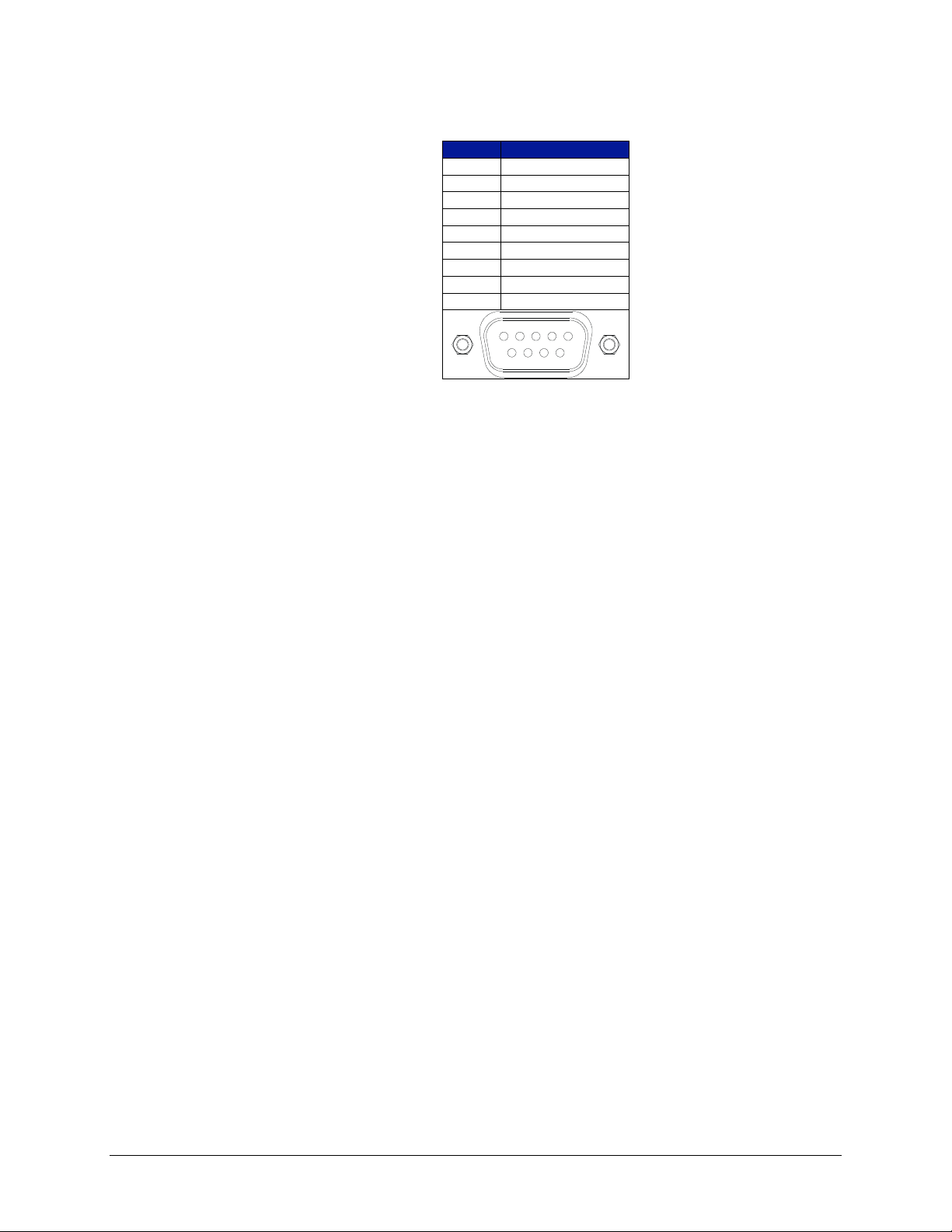
VTI Instruments Corp.
64 EX10xxA Triggering
information, and as a general purpose output device. The digital I/O connector is a standard DB-9
with the following pin assignment:
Pin
Function
1
DIO Channel 0
2
DIO Channel 1
3
DIO Channel 2
4
DIO Channel 3
5
DIO Channel 4
6
DIO Channel 5
7
DIO Channel 6
8
DIO Channel 7
9
GND
1 2 3 4 5
6 7 8 9
TABLE 3-7: DIGITAL I/O CONNECTOR & PIN ASSIGNMENT
As a general purpose output device, each DIO channel can be independently programmed with
regards to its output functionality and its static level to assume when enabled as an output. When
not enabled as an output, a channel becomes tri-stated, preventing conflict with other potential
voltage drivers. Reference the port’s electrical specifications in Table 3-8 for voltage tolerance
limits and output drive capabilities. Regardless of output functionality, each channel provides
constant input functionality. That is, the input level on each channel can be accessed without a
specific enable function call. Moreover, the base functionality of the DIO channels is not affected
by triggering, scanning, or any other instrument process. Unless linked to a limit condition, as
discussed below, its operation is completely autonomous.
When enabled as an output, each channel also has the ability to generate a 1 µs pulse upon command.
An example application of this pulse is to use the EX10xxA to externally trigger another piece of
test equipment. The specific operation of the pulse depends on the static level programmed for that
channel. When a channel is programmed with a static level of high, the pulse will be low-going.
When a channel is programmed with a static level of low, the pulse will be high-going. Each pulse
generation requires a separate function call.
For expanded and more automated operation, each DIO channel can be independently linked to one
or multiple limit conditions on one or more input channels. This is termed a DIO Limit Event. For
example, DIO channel 0 can be programmed to go high when the upper limit of set 0 for channel 2
or the lower limit of set 1 for channel 1 is exceeded. When linked as a limit event, a DIO channel
will be cleared at the beginning of a new acquisition. Its state will then be updated with each scan
according to the programmed limit evaluations. By default, the cleared state is low, but can be set
on a per channel basis to be high through the use of the Invert setting. Similarly, the default operation
of each channel is non-latch mode, but can be set on a per channel basis to be latch mode. In latch
mode, a transition out of the cleared state would remain, regardless of future limit evaluations, until
it is cleared at the beginning of a new acquisition.
It is important to note that the control of the DIO channels through DIO Limit Event assignment
does not lock out control through the direct output mechanism. For example, even if a DIO channel
has been set high by a DIO Limit Event, it could be asynchronously set low through direct output
control. Because limits can only be evaluated as fast as data is being acquired, there could be an
application that employs a slow sampling rate but requires the DIO channel to be reset sooner than
the normal limit evaluation mechanism would do it. The direct DIO control provides this capability.
Use of that control does not alter or disable the limit event mechanism controls; it simply
asynchronously alters the level of the DIO channel output. Upon the next scan (and subsequent limit
evaluation), the DIO channel will be updated normally per its DIO Limit Event configuration. In
general, however, an application will employ only one control mechanism. For that reason, if a DIO
Page 65
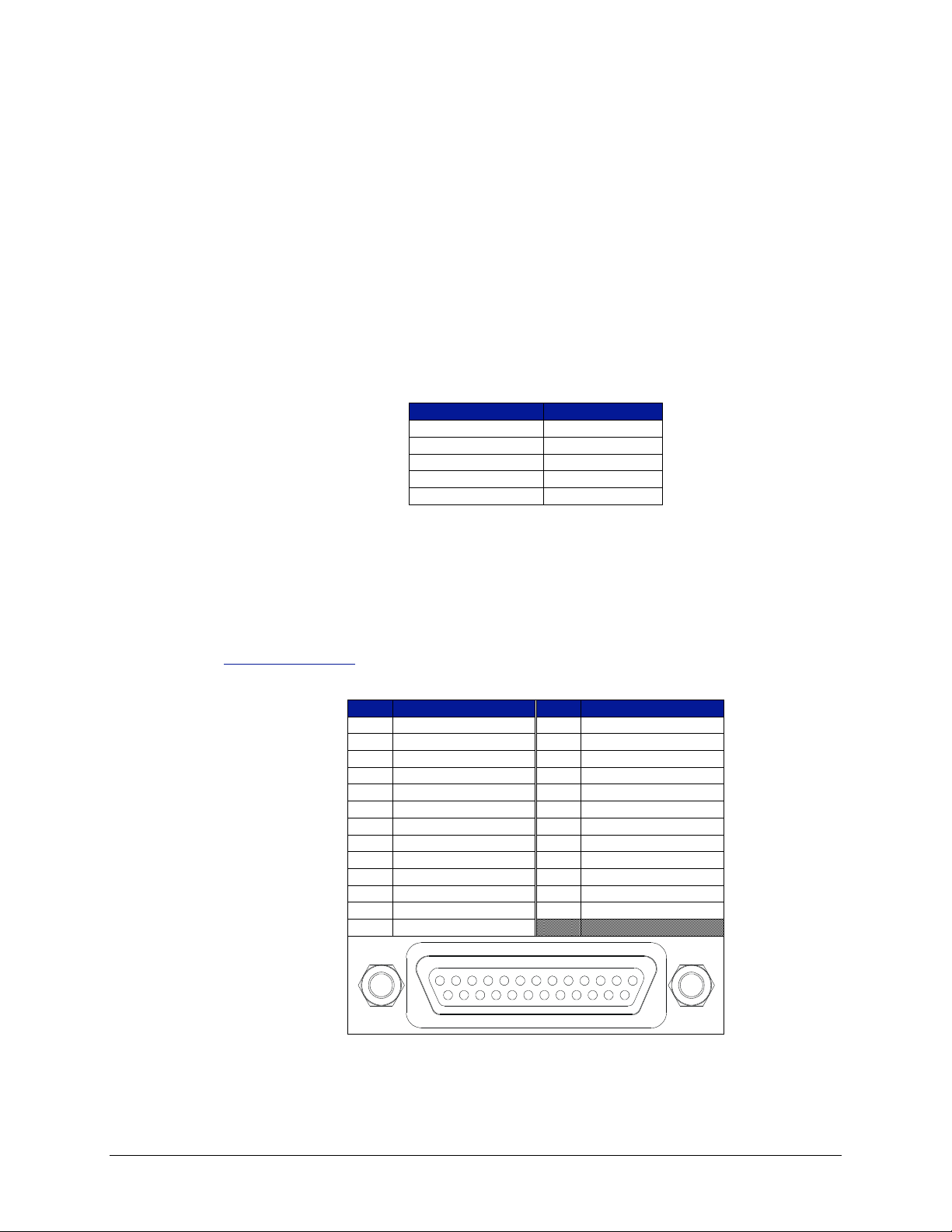
www.vtiinstruments.com
EX10xxA Triggering 65
channel is linked as a DIO Limit Event, this is noted in the direct control mechanism as a pseudowarning to guard against accidental use.
The default selections for each DIO channel are:
output enable is off
output level is 0
The default selections for DIO Limit Events are:
all channels are disabled
invert is off
latch is off
The electrical specifications for the digital I/O port are provided in Table 3-8. Particular note should
be given to the V
INPUT
specification of -0.5 V to 5.5 V. Exceeding that value with an external voltage
source, even though a resistance, could permanently damage the EX10xxA.
Characteristic
Value
V
INPUT
-0.5 V to 5.5 V
VIH
2 V min
V
IL
0.8 V max
VOH (IOH = -32 mA)
2 V min
VOL (IOL = 64 mA)
0.55 V max
TABLE 3-8: DIGITAL I/O PORT ELECTRICAL SPECIFICATIONS
LXI TRIGGER BUS
The EX10xxA series provides an LXI compatible trigger bus connector set on the rear panel of the
instrument. Both connectors have the same pin assignments and are wired in parallel. For more
information on the LXI Trigger Bus and creating an appropriate cable, please visit
www.lxistandard.org and refer to LXI Standard Revision 1.2 and LXI Trigger Bus Cable and
Terminator Specifications Rev 1.1.
Pin
Function
Pin
Function
1
+3.3 V
14
RP_TRIG_P0
2
GND
15
RP_TRIG_N0
3
RP_TRIG_P1
16
RESERVED
4
RP_TRIG_N1
17
RP_TRIG_P2
5
GND
18
RP_TRIG_N2
6
RP_TRIG_P3
19
GND
7
RP_TRIG_N3
20
RP_TRIG_P4
8
GND
21
RP_TRIG_N4
9
RP_TRIG_P5
22
GND
10
RP_TRIG_N5
23
RP_TRIG_P6
11
RESERVED
24
RP_TRIG_N6
12
RP_TRIG_P7
25
RESERVED
13
RP_TRIG_N7
1 2 3 4 5 6 7 8 9 10 11 12 13
14 15 16 17 18 19 20 21 22 23 24 25
TABLE 3-9: TRIGGER BUS CONNECTOR PIN ASSIGNMENT
Page 66
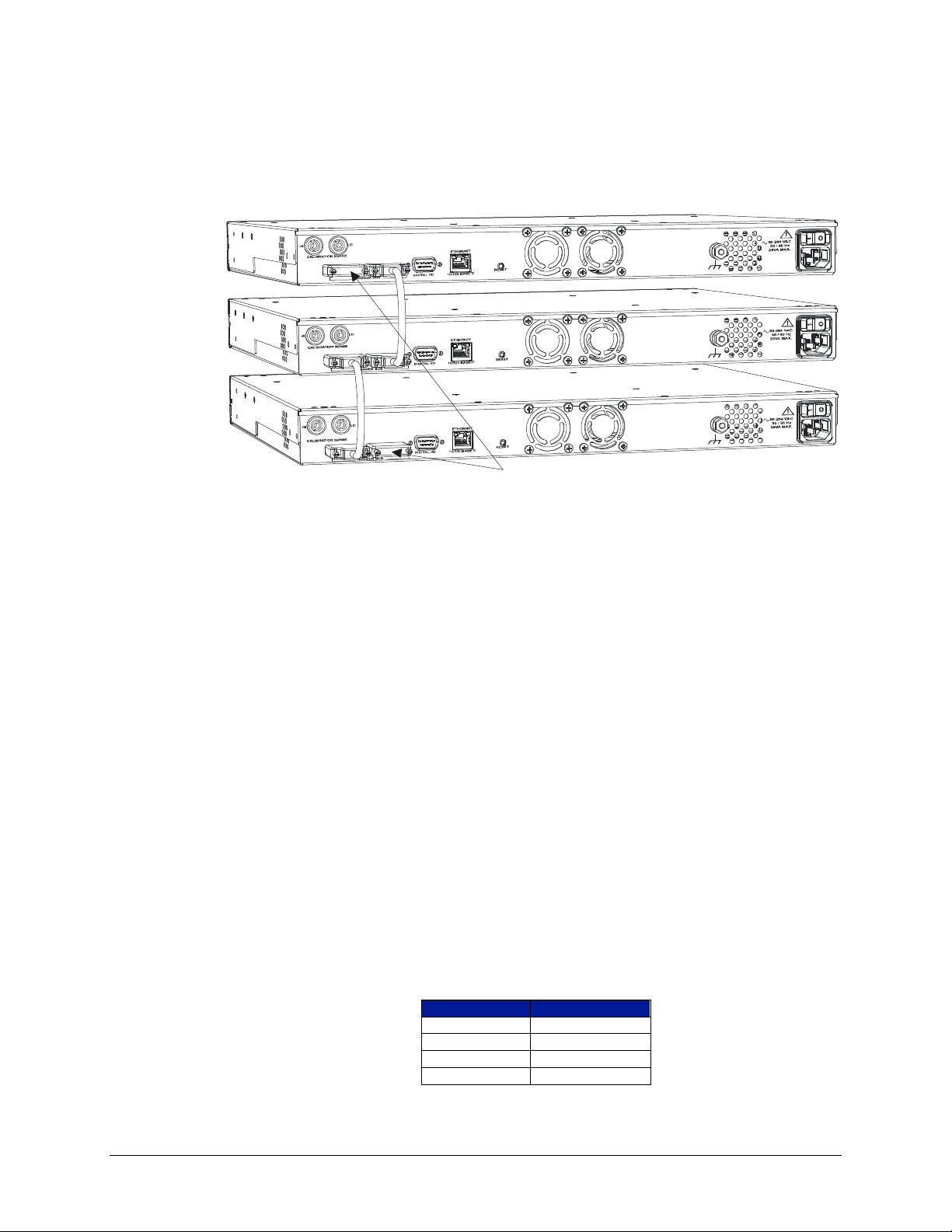
VTI Instruments Corp.
66 EX10xxA Triggering
For proper operation, each trigger bus connector must be populated with either a cable or a
termination. Since the two connectors per unit are in parallel, they are electrically equivalent with
respect to receiving the cable or termination. VTI Instruments P/N: 70-0304-000 provides two
termination assemblies, which is sufficient to connect any number of instruments, since a
termination is only needed at each end. An example of a three-unit trigger bus installation is shown
in Figure 3-1.
Trigger Bus
Terminators
FIGURE 3-1: TRIGGER BUS CABLING EXAMPLE
As a general purpose output device, each VTB channel can be independently programmed with
regards to its output functionality and its static level to assume when enabled as an output. When
not enabled as an output, a channel becomes tri-stated, preventing conflict with other potential
voltage drivers. Regardless of output functionality, each channel provides constant input
functionality. That is, the input level on each channel can be accessed without a specific enable
function call. Moreover, the base functionality of the VTB channels is not affected by triggering,
scanning, or any other instrument process.
When enabled as an output, each channel also has the ability to generate a 1 µs pulse upon command.
The specific operation of the pulse depends on the static level programmed for that channel. When
a channel is programmed with a static level of high, the pulse will be low-going. When a channel is
programmed with a static level of low, the pulse will be high-going. Each pulse generation requires
a separate function call.
A common application of the pulse generation is multiple-unit synchronization. Referring to
Figure 3-1 above, each unit can be configured to trigger on the same VTB channel. Then one unit
is selected as a master and is used to output a signal on the designated VTB channel line, serving as
a common trigger source for all three instruments.
The default selections for each VTB channel are:
output enable is off
output level is 0
The electrical specifications for the trigger bus are provided in Table 3-10.
Characteristic
Value
Logic Type
M-LVDS Type 2
V
IT+
150 mV max
V
IT-
50 mV min
VOS
1 V typical
TABLE 3-10: TRIGGER BUS ELECTRICAL SPECIFICATIONS
Page 67

www.vtiinstruments.com
EX10xxA Triggering 67
In addition to a single-master/multiple-slaves configuration, the LXI Trigger Bus can be configured
in Wired-OR mode. This mode allows multiple instruments to bring an LXI Trigger Bus channel to
a “1” state. The channel will only go back to “0” when all instruments have released it. This is useful
if multiple instruments in parallel operation must all complete before another instrument can begin
its operations. Each channel is programmable as to whether it is in Wired-OR or Master-Slave mode.
When an LXI Trigger Bus channel is configured for Wired-OR mode, exactly one instrument on the
bus must provide a bias on the channel. This is what allows the channel to fall deterministically back
to a “0” state when all other devices release it. Each channel is programmable as to whether it will
provide the Wired-OR Bias when it is in Wired-OR mode. default selections:
Wired-OR mode is off
Wired-OR Bias mode is off
LOCKING
By default, the EX10xxA allows unrestricted operation from multiple hosts, both through the web
page and instrument driver interfaces. While this offers a high level of user flexibility, there are
instances where protected operation is desirable, if not required. For these applications, the
EX10xxA can be “locked,” meaning that it will accept function calls from only the host IP address
that issued the lock function. With the EX10xxA in this mode, other host connections that attempt
to make calls will be denied.
By design, the locking mechanism is able to be overridden by a secondary host that issues a break
lock command. Thus, the lock provides a warning to other users that the unit is in a protected
operation state, but not absolute security. This allows for instrument recovery if the locking IP
address would become disabled.
Self-calibration requires the acquisition of a lock prior to its initiation.
TRIGGERING
The EX10xxA supports a full function trigger model with a separate arm source and trigger source
event structure. For a complete explanation of the trigger model, see Error! Reference source not
found.. In summary, an acquisition sequence is enabled with a trigger initialize command. Scanning
is then initiated upon the receipt of the programmed arm source event followed by the receipt of the
programmed trigger source event. Trigger and arm source events can be independently programmed
from a variety of sources including Immediate, Timer, Digital I/O, the LXI Trigger Bus, and LXI
alarms.
DATA FORMAT
By default, the data returned during data retrieval is limited to the channel readings and the absolute
time of scan initiation. If enabled, the EX10xxA can also return the measured CJC temperatures and
the delta timestamp of each channel reading from the scan initiation time.
ACQUIRING DATA
In general, the acquisition and retrieval of data on the EX10xxA are conducted with discrete
commands that are often separated in time to a large degree. The EX10xxA utilizes a 14 MB FIFO
memory storage to buffer acquisition data prior to retrieval. This reading buffer is cleared upon
receipt of the trigger initialize command in preparation for reading storage. Then, upon fulfillment
of the programmed trigger model conditions, the EX10xxA initiates the scanning of the channel
configuration that is defined in the scan list. It continues scanning and storing the acquisition data
until the trigger and arm count quantities are reached or the acquisition is aborted. At that point,
scanning ceases, and the trigger model is returned to the INIT layer.
Page 68
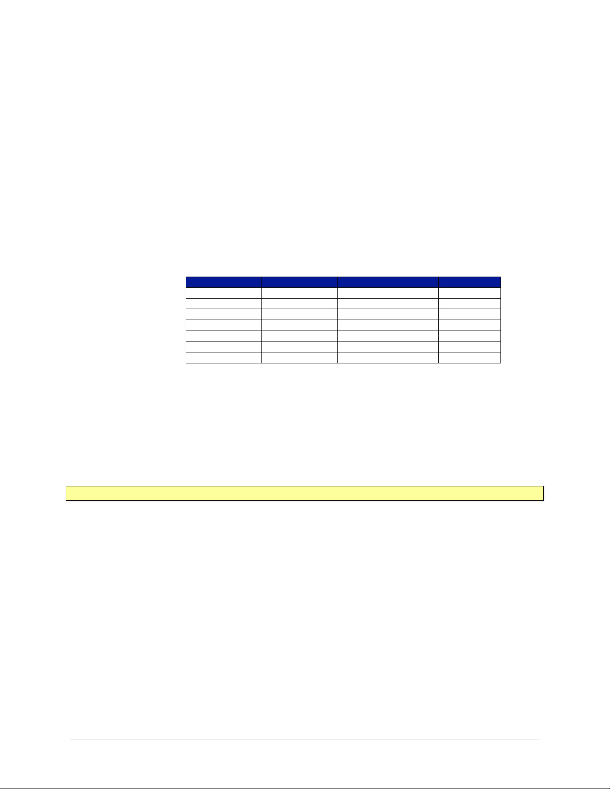
VTI Instruments Corp.
68 EX10xxA Triggering
The amount of scans that can be buffered within the memory is dependent on the number of channels
in the scan list and the requested data format. For this reason, very long scan sequences (in terms of
count) will benefit from a minimization of the data format, so as to maximize the number of scans
that can be stored. Specifically, the number of scans that can be buffered (Page_Count) is determined
by the following formula:
ReportingTimestamp_24zeChannel_Si
ReportingTimestamp_24l_SizeCJC_Channe
ingCJC_Report21l_CountCJC_Channe
l_SizeCJC_Channel_CountCJC_ChannezeChannel_SiuntChannel_Co29Page_Size
Page_Size / 14680064Page_Count
where: Channel_Count 1-48 (number of channels in scan list)
CJC_Reporting 0 or 1 (1 = YES, 0 = NO)
Timestamp_Reporting 0 or 1 (1 = YES, 0 = NO)
Page_Count sizes for some typical configurations are the following:
Channel_Count
CJC_Reporting
Timestamp_Reporting
Page_Count
1 0 0
152916
16 0 0
94101
32 0 0
66726
48 0 0
51689
48 1 0
44216
48 0 1
38630
48 1 1
32477
TABLE 3-11: EXAMPLE PAGE COUNT SIZES
If the reading buffer fills to its maximum capacity during scanning, the behavior with regards to
additional readings is governed by the setting of the instrument’s blocking mode. With blocking
mode enabled, additional readings are discarded, leaving the contents of the buffer intact. With
blocking mode disabled, the buffer becomes circular, in that additional readings overwrite the oldest
readings.
The default selection for blocking mode is disabled.
NOTE The reading buffer memory is volatile and is cleared upon an instrument reset or power cycle.
RETRIEVING DATA
In general, acquisition data is retrieved from the EX10xxA upon the completion of the acquisition.
This mode of operation is fully supported by the embedded web page as well as the instrument
driver. In addition, data retrieval in the midst of an acquisition sequence is supported by the
instrument driver. In either case, retrieved data is fully calibrated and compensated by the EX10xxA
and output directly in the requested units. No post-acquisition user manipulations are required. Data
can be retrieved one page (scan) at a time or downloaded in multiple page blocks up to the maximum
number of pages that exist on the instrument at the time of retrieval. In order to provide the
maximum reading buffer capacity for future acquisitions, data is deleted from the FIFO memory
upon retrieval.
Applications may retrieve data from this FIFO using either the Read FIFO or Streaming Data
interfaces. Please refer to the Retrieving Data (Read FIFO and Streaming Data) section for further
details. Once data is retrieved from the FIFO, via either method, it is no longer kept within the FIFO.
Page 69

www.vtiinstruments.com
EX10xxA Triggering 69
USER-DEFINED CONVERSIONS
The EX10xxA nominally accepts standard thermocouple types and performs its thermocouple
calculations using polynomial coefficients from the NIST ITS-90 Thermocouple Database. In some
applications, however, a user may want to override the embedded coefficients with a user-defined
coefficient set. One reason to do this is if the transfer function of the specific thermocouple being
used has been completely characterized to an accuracy level that exceeds standard thermocouple
limits of error. Another reason to do this is if a non-standard thermocouple is used. Up to two unique
sets of coefficients can be entered. Specifically, the use of custom thermocouple equations requires
the user to know or generate the coefficients for two conversion polynomials.
The forward conversion polynomial is used to convert a CJC temperature into a compensating cold
junction voltage and has the form of:
12
12
2
2
1
10
*** tctctccE
where E is in volts, t is in ºC, and c0 - c12 are the coefficients.
The inverse conversion polynomial is used to convert a compensated input voltage into temperature
and has the form of:
12
12
2
2
1
10
*** EdEdEddt
where E is in volts, t is in ºC, and d0 - d12 are the coefficients.
The default values for the coefficients are 0.0.
NOTE The entry of user-defined coefficients does not automatically enable their use. The enabling is done
by setting the EU conversion to User0 or User1.
Page 70
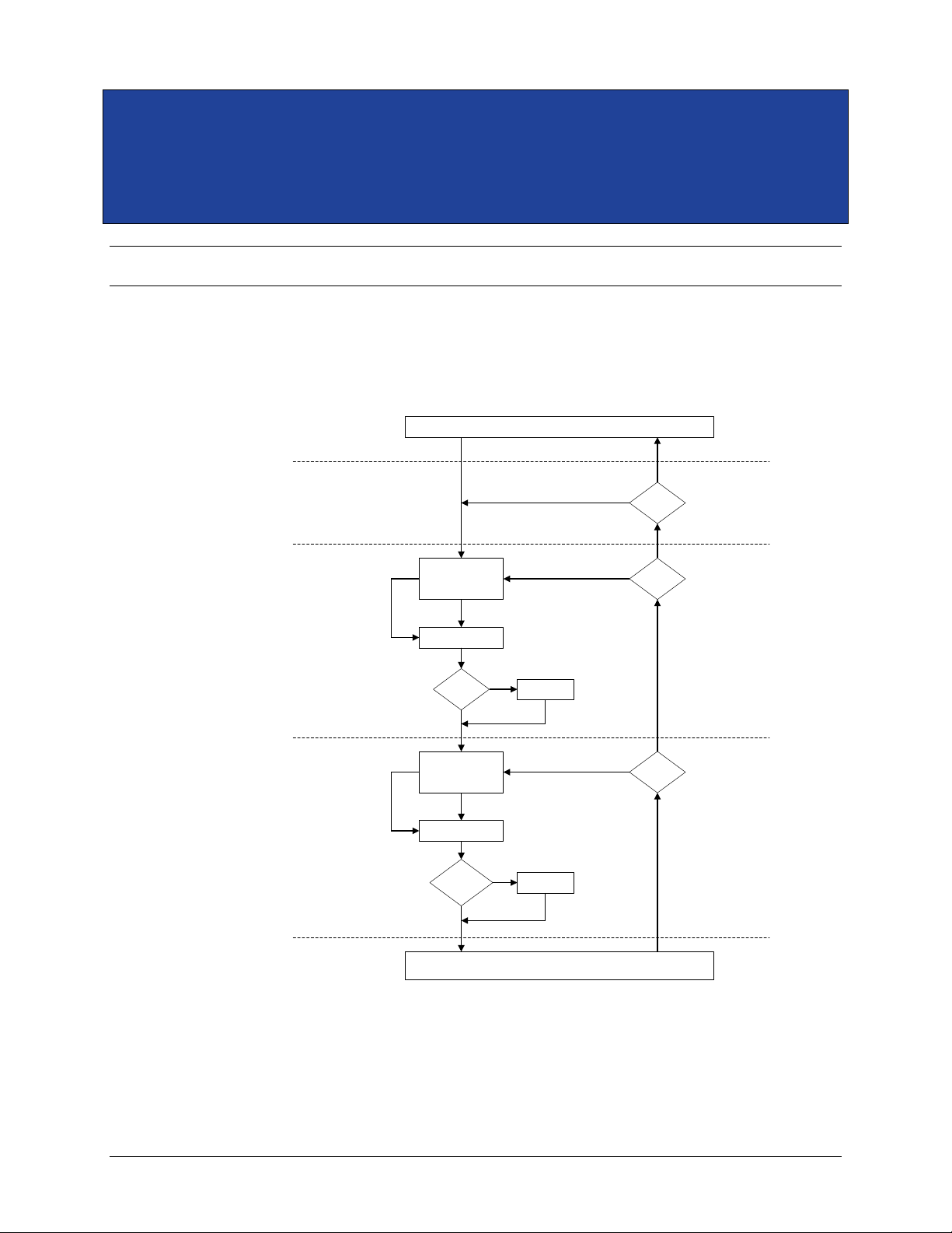
VTI Instruments Corp.
70 EX10xxA Triggering
SECTION 4
TRIGGERING
OVERVIEW
The EX10xxA supports a full function trigger model with a separate arm source and trigger source
event structure. The trigger model is based on the industry standard SCPI 1999 Trigger Subsystem
and is diagramed in Figure 4-2.
IDLE
IDLE
LAYER
ARM
LAYER
TRIG
LAYER
INIT
LAYER
DEVICE
LAYER
Init
Continuous?
No
Init
Yes
Wait for
ARM Event
ARM Delay
ARM Event
ARM:Count > 0
or
ARM:Count:Inf?
No
Yes
Software Arm
ARM:COUNT:INF?
Decrement
ARM:COUNT
No
Yes
TRIG:Count > 0
or
TRIG:Count:Inf?
No
Wait for
TRIG Event
TRIG Delay
TRIG Event
Software Trigger
TRIG:COUNT:INF?
Yes
Yes
RUN SCAN LIST
Decrement
TRIG:COUNT
No
FIGURE 4-2: EX10XXA TRIGGER MODEL
Page 71

www.vtiinstruments.com
EX10xxA Triggering 71
The trigger model is sectioned into five layers: IDLE, INIT, ARM, TRIG, and DEVICE. The
EX10xxA reset condition places it in the IDLE state. A trigger initialize command begins the
acquisition sequence by transitioning the instrument through the INIT layer into the ARM layer. As
this occurs, the reading buffer memory is cleared, and all enabled limit events are reset to their
default states.
Upon entering the ARM layer, the ARM Count is reset to its specified value. The instrument remains
in the ARM layer until the specified ARM event occurs or a Software Arm is issued. Once that
occurs, the specified ARM Delay is waited, the ARM Count is decremented, and the instrument
transitions into the TRIG layer.
Upon entering the TRIG layer, the TRIG Count is reset to its specified value. The instrument
remains in the TRIG layer until the specified TRIG event occurs or a Software Trigger is issued.
Once that occurs, the specified TRIG Delay is waited, the TRIG Count is decremented, and the
instrument transitions into the DEVICE layer.
In the DEVICE layer, the scan list is measured, calibrated, and stored into local memory. In addition,
limit evaluation is conducted, and enabled limit event states are updated.
If the TRIG Count remains nonzero, the instrument stays in the TRIG layer until the specified TRIG
event (and subsequent device action) occurs enough times to decrement it to zero. Once the TRIG
Count reaches zero, the instrument then evaluates the remaining ARM Count and repeats the ARM
layer action if it is nonzero. However, since each transition into the TRIG layer resets the TRIG
Count, each additional ARM layer action results in the full specified number of TRIG Count actions
through the TRIG layer and DEVICE layer.
Once the ARM Count reaches zero, the instrument transitions back into the INIT layer. If Init
Continuous mode is enabled, the ARM layer is automatically reentered without the issuance of a
trigger initialize command. However, unlike with a trigger initialize, enabled limit events are not
reset, and the reading buffer memory is not cleared. Conversely, if Init Continuous mode is disabled,
the instrument is returned to the IDLE layer and requires the issuance of a new trigger initialize
command to begin a new acquisition sequence.
EVENTS
There are two events that control the progress through the trigger model: the ARM event and the
TRIG event. Each of these events can be programmed independently to be activated from any
combination of the Trigger Bus, Digital I/O port, LAN events, internal system timer, and LXI alarm.
In addition, the Trigger Bus, Digital I/O port, and timer can be programmed to be Immediate,
creating a permanent satisfaction of the event monitor. Each event monitor can also be bypassed on
command with the issuance of a Software Arm or Software Trigger, as appropriate. Software Arms
and Software Triggers are always enabled, regardless of the other programmed event sources.
The Digital I/O port and the Trigger Bus monitor the digital hardware ports on the rear panel of the
instrument. An event can be controlled by any combination of the eight channels of each port.
Moreover, each channel can be independently programmed to monitor a transition edge or a level.
LAN Events are triggered through the eight LAN Event channels via Ethernet packets
(UPD/multicast or TCP messages). They are configured in a manner similar to the Digital I/O port
and Trigger Bus. These events can occur in “past time”, “now”, or “future time”. “Past time” events
have an IEEE 1588 time that occurred in the past. They function essentially as an immediate (or
“now” event), but, unlike the “Now” event, provide both sent and received information for
debugging purposes. “Now” events have a IEEE 1588 time of “0”, indicating that the event will
occur immediately after it is received). Because they have a time of “0”, the event log will only
identify when this event was received. “Future time” events have an IEEE 1588 time that has not
yet occurred. Because these events occur in the future, they can be prepared for an provide a better
response time than either “past” or “now” events. For more information on LAN Events, please see
the LAN Events Menu in Section 4.
Page 72
VTI Instruments Corp.
72 EX10xxA Triggering
The instrument’s internal system timer generates ticks at the specified timer interval, where each
tick represents a unique event. For example, a TRIG event source set to Timer at a timer interval of
0.005 s will generate internal triggers at a rate of 200 Hz.
The LXI alarm is specified by IVI 3.15, IVILxiSync specification. Similar to the timer, the LXI alarm
will cause an event, but these events are based on IEEE 1588 time and always occur at the preprogrammed time. The alarm period can be set for this event as well, allowing the LXI alarm to fire
repeatedly at a defined interval.
As previously mentioned, an event condition can be designated to be any combination of Trigger
Bus channel transitions or levels, Digital I/O channel transitions or levels, and Timer ticks. If
multiple sources for an ARM event are specified, they are logically combined as follows:
ARM event = [(Timer tick event) AND (LXI alarm event) AND (LAN event) AND (Digital I/O event) AND (Trigger
Bus event)]
If multiple sources for a TRIG event are specified, they are logically combined as follows:
TRIG event = [(Timer tick event) AND (LXI alarm event) AND (LAN event) AND (Digital I/O event) AND (Trigger
Bus event)]
Within each digital hardware port (and LAN events), it is also possible to select multiple channels
and multiple conditions for a specific channel. In that case, they are logically combined as follows:
Digital I/O event = (Ch 7 events) AND (Ch 6 events) … AND (Ch 0 events)
Finally, within each channel, the four event conditions of Pos. Edge, Neg. Edge, Pos. Level, and
Neg. Level are OR’ed together.
As an example, if a Digital I/O event is specified to be a combination of a Pos. Level on channel 3,
a Pos. Edge on channel 6, and a Neg. Edge on channel 6, the event will be satisfied when a Pos.
Level on channel 3 occurs simultaneously with a Pos. Edge or a Neg. Edge transition on channel 6.
While the Digital I/O event structure was used as an example, the Trigger Bus event structure
operates in the same manner.
NOTE The extensive flexibility of the trigger model system permits the creation of very specialized trigger
conditions, which is a powerful application tool. However, it also permits the creation of trigger
conditions that would be very difficult to satisfy in practice. For example, if edge conditions are
specified on multiple digital hardware channels, the edges must occur within 25 ns of each other to
be recognized as having occurred simultaneously. Similarly, the timer source should not be
combined with any digital hardware edge conditions.
MAXIMIZING MEASUREMENT PERFORMANCE
As explained in Sampling Rate / Noise Performance in Section 3, the EX10xxA takes advantage of
a sampling rate setting of less than 1 kSa/s to acquire and average multiple samples. This offers
improved noise performance, while maintaining the requested data output rate. However, the trigger
model must be configured in a specific manner to allow this to occur. Specifically, the TRIG event
source must be configured for Timer or LXI alarm must be enabled and configured. This is critical,
because only under this condition does the EX10xxA know exactly the rate and timing of the trigger
events. That is, it knows the available time in which to complete the acquisition and consequently
how many samples it can average and still complete the entire scan list. With any other trigger
source, the triggers can occur at any time. In that case, the EX10xxA completes the scan list in
minimum time and does not average.
Page 73

www.vtiinstruments.com
EX10xxA Triggering 73
If the desired trigger model configuration requires the use of the digital I/O port and/or the trigger
bus, it is thus best to configure the ARM source for the required digital event, leaving the TRIG
source as Timer. The TRIG source should be changed from Timer only in the situation where
triggering is required on a two-stage digital event. An example of this is arming on a digital I/O
channel level and then triggering on a trigger bus channel edge.
MAXIMUM TRIGGER RATE
The ability to configure the TRIG event source to be an external event such as a Digital I/O channel
level or a Trigger Bus channel edge is a powerful test feature, allowing measurements to be precisely
correlated with external events. External events, however, could nominally be generated at a rate far
faster than the EX10xxA can completely and correctly execute the DEVICE layer. To prevent the
instrument from being overdriven, the trigger model contains an internal pacer timer. Once the
trigger event has been satisfied, this timer disables the recognition of all trigger events for a time
period of 1 ms. Trigger events that occur during this 1 ms period are ignored, not buffered. This is
similar in concept to the fact that, for example, additional ARM events are ignored if the trigger
model is not specifically waiting for an ARM event. Due to this action, triggering the EX10xxA
with a burst of external pulses that exceeds 1 kHz will result in not only fewer readings than trigger
events, but also a reading rate that is potentially far less than the maximum rate.
Consider an example in which the trigger model is set to the following configuration:
Init Continuous Disabled
Timer Interval 0.1
Arm Source Immediate
Arm Count 1
Arm Delay 0
Trig Source DIO Channel 0 Positive Edge
Trig Count 1
Trig Delay 0
Once initialized, the EX10xxA is driven by a burst of 100 positive edge transitions at a rate of
1.5 kHz. At 1.5 kHz, the time between trigger events is 990 µs. Since this time is less than 1 ms,
every other trigger event will be ignored. Consequently, this burst will generate 50 readings at a rate
of 750 Hz. Note that the actual reading output rate is far less than the 1 kSa/s maximum rate. To
achieve the maximum output rate, the TRIG event source should be set to Immediate or Timer (with
a Timer Interval of 0.001).
Page 74

Page 75
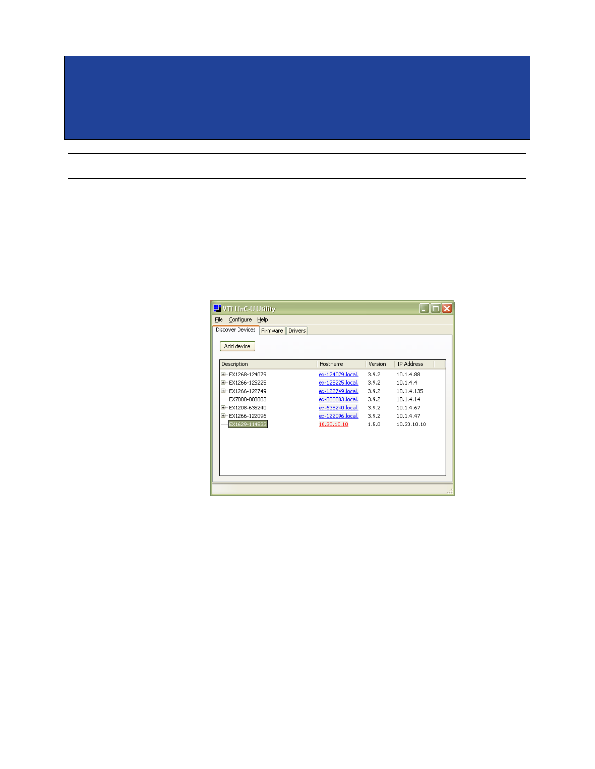
www.vtiinstruments.com
EX10xxA Web Page Operation 75
SECTION 5
WEB PAGE OPERATION
INTRODUCTION
To open the embedded web page, start the LInC-U utility by navigating to Start → Programs →
VTI Instruments Corporation → LInC-U Utility → LInC-U Utility. Once the utility is run,
LInC-U will scan the network to discover all LAN-based VTI instruments. Once the scan is
complete, the Discovery Devices tab will appear and show the instruments that were discovered, as
shown in Figure 5-1. To open the web page, click on the hostname hyperlink on the Discover
Devices tab. The IP address of the EX10xxA can also be viewed from this window as well as its
firmware version.
FIGURE 5-1: LINC-U DISCOVERY TAB WITH EX10XXA SELECTED
Alternatively, the EX10xxA may also be discovered using Internet Explorer’s Bonjour for Windows
plug-in. The IP address of the EX10xxA can also be entered into the address bar of any web browser
to view the embedded web page. By default, the EX10xxA will first attempt to use DHCP to set its
IP Address. If DHCP is not available on the network it is connected to, it will instead use Auto IP.
Determining the Auto IP address is discussed in the Network Configuration discussion in Section 2.
Other discovery methods, such as VXI-11, can be used as well.
GENERAL WEB PAGE OPERATION
When initial connection is made to the EX10xxA, the instrument home page appears. This page
displays instrument-specific information including:
Vendor
Serial number
Description
Page 76
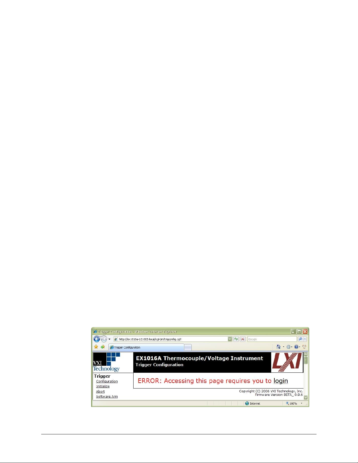
VTI Instruments Corp.
76 EX10xxA Web Page Operation
LXI Information
Hostname
MAC Address
Netmask
Instrument Address String
Firmware version
Date of last full calibration
Presence of nonvolatile self cal data
Error status
IEEE 1588 PTP Time
This page is accessible from any other instrument page by clicking on the instrument name in the
web page header.
All of the configuration, data acquisition, and data retrieval features available through the web page
are accessed through the EX10xxA command menu that is displayed on the left hand side of every
internal web page. The entries on the command menu represent three types of pages:
Status This type of page performs no action and accepts no entries. It provides
operational status and information only. The EX10xxA Main page is an
example of a status page.
Action This type of page initiates a command on the instrument, but does not
involve parameter entry. The Trigger…Initialize page is an example of
an action page.
Entry This type of page displays and accepts changes to the configuration
controls of the instrument. The Scan List…Configuration page is an
example of an entry page.
Use of the entry-type web pages in the EX10xxA are governed by a common set of operational
characteristics:
Each page contains two standard buttons: Apply.
Pages initially load with the currently-entered parameters or selections displayed.
Changes that are made after the initial load are not accepted until the Apply button is clicked.
Once the Apply button is clicked, the page will reload, showing the new state of the page.
Navigation through a parameter screen is done with the Tab key. The Enter key has the same
function as clicking the Apply button and cannot be used for navigation.
When accessing an action or entry page for the first time during a session, an Error page will appear.
To clear this error, click on the login link. The Login page will appear. In the Password field, enter
ex1048.
FIGURE 5-2: LOGIN ERROR PAGE
Page 77
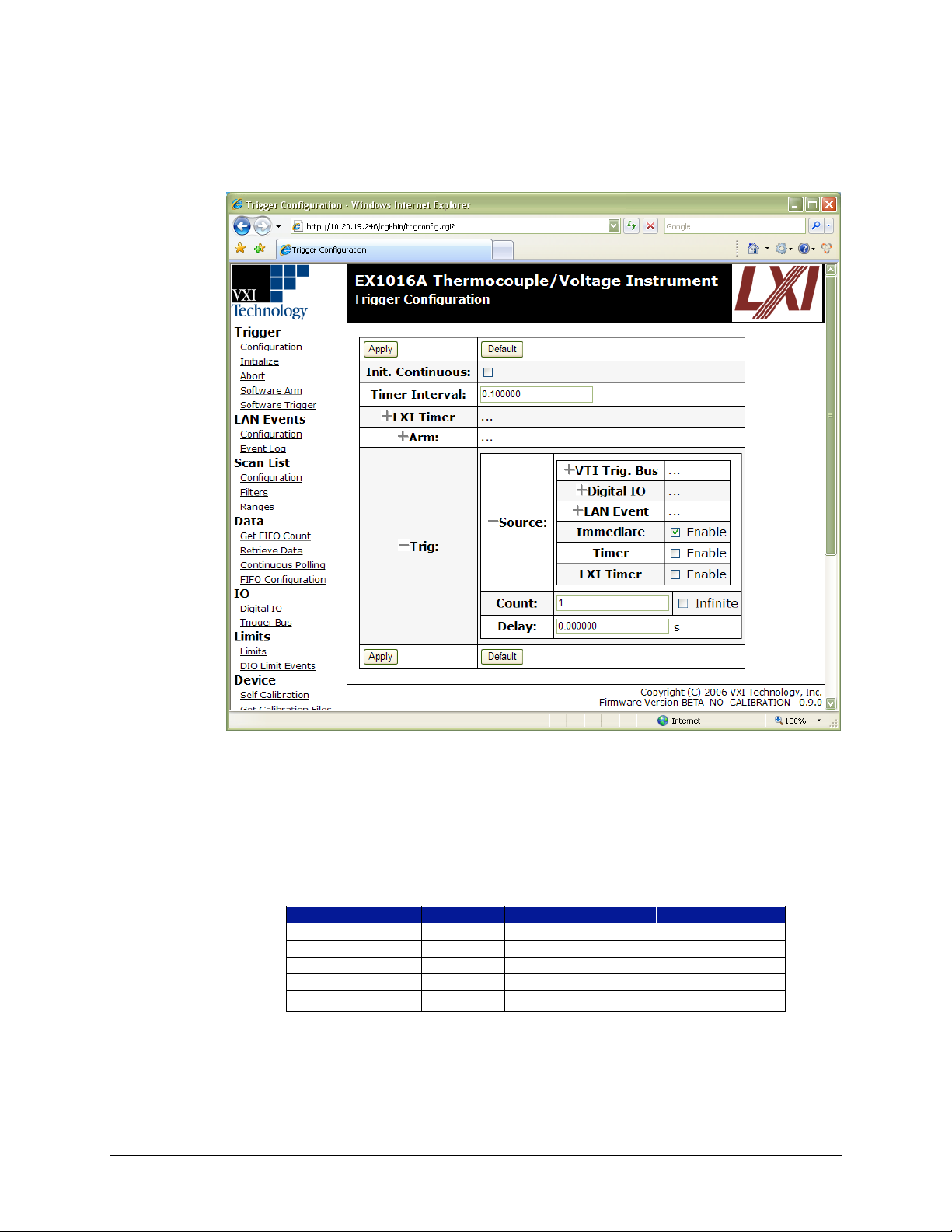
www.vtiinstruments.com
EX10xxA Web Page Operation 77
TRIGGER MENU
The Trigger menu is used to configure and operate the EX10xxA’s trigger system.
Configuration
FIGURE 5-3: TRIGGER PAGE
This entry page is used to configure the arm and trigger sources of the EX10xxA. The page is
designed with a collapsible and expandable menu structure that is retained between page visits. This
allows the user to expose only as much as the trigger system as needed, making navigation through
the configuration options easier. Detailed information on triggering is provided in Error! Reference
source not found.. Most of the controls on this page are checkboxes to enable different levels of
functionality. The rest are parameter entry fields that have the following valid input ranges:
Parameter
Min
Max
Resolution
Timer Interval (s)
0.001
4294
0.000001
Arm Count
1
(231-1)
1
Arm Delay (s)
0
4294
0.000001
Trig Count
1
(231-1)
1
Trig Delay (s)
0
4294
0.000001
TABLE 5-1: TRIGGER CONFIGURATION PARAMETER RANGES
In addition to the two standard buttons, this page also provides a Default button. This button
provides a one-click method of returning all trigger configuration parameters to their reset values.
Page 78

VTI Instruments Corp.
78 EX10xxA Web Page Operation
It should be noted that the use of this button does not eliminate the need to click the Apply button
to accept the changes.
Initialize
Clicking on this link will begin an acquisition, transitioning the trigger model from the IDLE layer
to the ARM layer. This command clears the FIFO reading memory and resets all limit indications.
Abort
Clicking on this link will abort the current acquisition and returns the trigger model to the IDLE
layer. Once an acquisition has begun, most commands are not accessible. The abort command is
used to prematurely end the acquisition in order to make configuration changes. Acquired data is
not affected by the issuance of an abort.
Software Arm
Clicking on this link will perform a software arm of the trigger model. Software arms are always
enabled as an ARM source and can be used to perform a bypass of the configured ARM source. The
software arm applies at the time it is issued and will be ignored if the system is not waiting for an
ARM event. The issuance of a software arm has no effect on the ARM source configuration.
Software Trigger
Clicking on this link will perform a software trigger of the trigger model. Software triggers are
always enabled as a TRIG source and can be used to perform a bypass of the configured TRIG
source. The software trigger applies at the time it is issued and will be ignored if the system is not
waiting for a TRIG event. The issuance of a software trigger has no effect on the TRIG source
configuration.
LAN EVENTS MENU
LAN events are used for device communication over Ethernet. The LAN events menu is used to
configure the EX10xxA’s LAN event arm and trigger lines.
Configuration
This entry page is used to define how the EX10xxA responds to LAN events. Each LAN event
trigger line can be set to arm or trigger on a packet with the same event ID as specified in the Event
ID field (default values shown below). Note that each line can arm or trigger on different LAN
events (i.e. LAN event line LAN0 could arm on Event ID LAN1, but trigger on Event ID LAN3).
Additionally, the user can use the Filter field to specify which network hosts are allowed to trigger
the LAN event line. The format of this field should be “hostname:port”. When the hostname is set
to blank or “” (default), the EX10xxA will accept all UDP and TCP packets on port 5044. If set to
“ALL”, the instrument will allow multicast UDP packets.
From this page, the user can also set the instrument’s LAN Domain and configure the LAN event
log. By clicking on the Log Enable checkbox, the EX10xxA will record LAN events as they occur.
The Log Overflow Mode radio buttons affect how the log buffer will operate once it becomes full.
If Overwrite Old is selected, the existing log will be overwritten by new LAN events, while
selecting Ignore New will ignore all LAN events that occur after the buffer is full.
Page 79
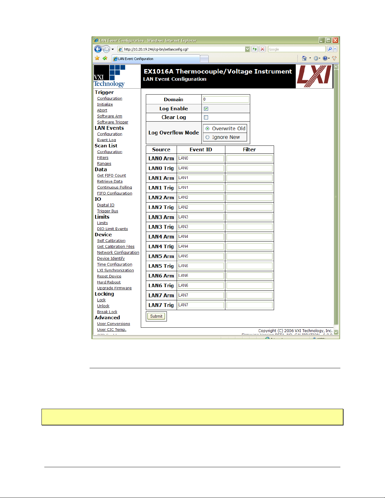
www.vtiinstruments.com
EX10xxA Web Page Operation 79
FIGURE 5-3: LAN EVENT CONFIGURATION PAGE
Event Log
This status page allows the user to view the LAN event log, when enabled. The data is provided in
a line-by-line manner. Clicking the Get Next Line link allows the user to view the next
chronological LAN event. The Clear Text Field link erases the LAN event that is currently being
displayed.
NOTE Once an event log entry is viewed from this page, it can no longer be accessed through the instrument
driver as it is immediately erased after being viewed.
Page 80
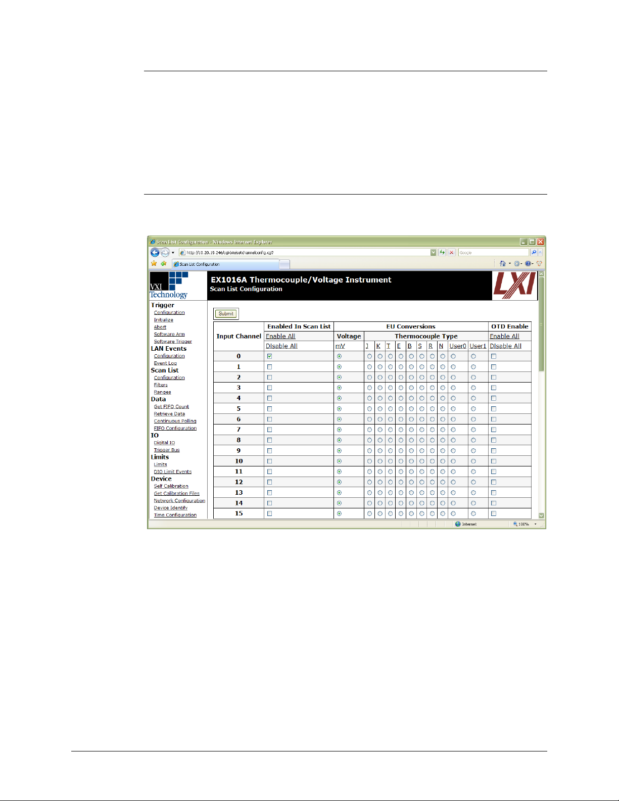
VTI Instruments Corp.
80 EX10xxA Web Page Operation
Status
This status page shows the trigger and arm states for all eight LAN event lines. If a “0” is shown in
the state field, the associated LAN event line is in a low state. If a “1” is shown, the line is in a high
state.
SCAN LIST MENU
The Scan List menu is used to configure the EX10xxA input channels with regards to scan list
inclusion, EU conversion, and hardware filter setting.
Configuration
This entry page is used to define the channel scan list and the EU conversion setting for each
channel. An example of this page is shown Figure 5-4.
FIGURE 5-4: SCAN LIST CONFIGURATION PAGE
This screen displays that currently channel 0 is enabled in the scan list and is set to perform voltage
measurements. Channels are enabled or disabled in the scan list by toggling the appropriate
checkbox. Additionally, all channels can simultaneously be enabled or disabled by clicking on the
Enabled or Disabled link. If the channel is a voltage channel, the Voltage radio box will be selected.
For thermocouple channels, the EU conversion is set by clicking the appropriate radio button under
the desired conversion type. Additionally, all channels can simultaneously be set to the same
conversion type by clicking on the appropriate link. It should be noted that the use of these links
does not eliminate the need to click the Apply button to accept the changes. The user can also
enable/disable OTD on either a per channel or global basis form by using the OTD Enable check
boxes.
Page 81

www.vtiinstruments.com
EX10xxA Web Page Operation 81
Filters
This entry page is used to define the hardware filter setting for each channel. Each channel’s
hardware filter is set by clicking the appropriate radio button under the desired frequency value.
Additionally, all channels can simultaneously be set to the same frequency value by clicking on the
appropriate link. It should be noted that the use of these links does not eliminate the need to click
the Apply button to accept the changes.
Ranges
This entry page is used to define the each channel’s input voltage range. Each channel’s voltage
range is set by clicking the appropriate radio button under the voltage range value. It should be noted
that the use of these links does not eliminate the need to click the Apply button to accept the changes.
DATA MENU
The Data menu is used to retrieve data from the EX10xxA as well as configure the format of the
data to be acquired.
Get FIFO Count
This status page displays how many pages (scans) worth of acquisition data have yet to be retrieved.
Retrieve Data
This action page extracts and displays one page (scan) worth of acquisition data on a first-in, firstout (FIFO) basis. If this page is invoked when the FIFO is empty, an error is returned. In order to
provide the maximum reading buffer capacity for future acquisitions, data is deleted from the FIFO
memory upon retrieval.
Continuous Polling
This action page is used to continuously trigger and retrieve one page (scan) of data from the
EX10xxA at a refresh rate of approximately once every three seconds. It is very useful for general
data monitoring, installation debugging, and instrument control familiarization. It cannot, however,
be used to test the trigger system, as it must alter the trigger configuration settings in order to acquire
data. Once continuous polling is initiated, it can be stopped by clicking the Stop Polling button or
a link to another page. Using the button preserves the most recent data screen.
NOTE Use of the Continuous Polling page alters the trigger configuration settings. Any previously entered
configuration settings must be reentered.
FIFO Configuration
This entry page is used to control the data format and overflow behavior of the FIFO memory.
The Report CJC Temperatures control enables the reporting of the CJC temperatures in the
acquisition data. This control does not affect their measurement, only the display of the data. The
CJC temperatures are taken with every scan, regardless of this control. Reported CJC temperatures
are always in units of ºC, regardless of the Temperature Units selection.
The Report Timestamps control enables the reporting of delta timestamps per channel in the
acquisition data. The timestamp represents the time, in increments of 100 ns, between the specific
channel measurement and the scan initiation time.
The Temperature Units selection controls whether the input channel data is returned in units of ºC
or ºF. This setting has no effect on the reported CJC data or data for input channels that are
configured for an EU conversion of mV.
Page 82

VTI Instruments Corp.
82 EX10xxA Web Page Operation
The Blocking Mode control governs the system behavior if the reading buffer fills to its maximum
capacity during scanning. With blocking mode enabled, additional readings are discarded, leaving
the contents of the buffer intact. With blocking mode disabled, the buffer becomes circular, in that
additional readings overwrite the oldest readings.
IO MENU
The IO menu is used to receive and output data through the digital I/O port and trigger bus of the
EX10xxA.
Digital IO
This entry page is used to monitor the state of the 8-channel digital I/O port and control it as a
general purpose output device. Each DIO channel can be independently programmed with regards
to its output functionality, its static level to assume when enabled as an output, and pulse operation.
The Input State status section displays the measured digital level (0 or 1) of the DIO channels each
time the page is accessed or refreshed. The information does not update automatically on an input
level transition or on a timer. Consequently, it should only be used to monitor static or slowly
changing levels. The input monitoring functionality operates regardless of the state of the Output
Enable control.
The Output State control provides a pull-down selection in which the output level of each DIO
channel is specified. This setting represents the level that the channel will assume if/when enabled
as an output. When a channel is not enabled, this selection has no effect.
The Output Enable control enables each DIO channel as an output. Once enabled, a channel will
assume the level specified in the Output State control. When not enabled as an output, a channel
becomes tri-stated.
NOTE Before specifying a DIO channel as an output, ensure that no other active voltage drivers are
connected to the channel. Otherwise, incorrect operation or instrument damage could result.
The Pulse control is used to generate a single-shot 1 µs pulse. The specific operation of the pulse
depends on the static level programmed for that channel. When a channel is programmed with a
static level of high, the pulse will be low-going. When a channel is programmed with a static level
of low, the pulse will be high-going. Each pulse generation requires a separate command. This
control is only valid when the channel is enabled as an output. Normally, pulse operation is used
once a channel’s static output level is already defined. However, if selections are applied together
to change the output state and output a pulse, the channel will first assume the new output state and
then output the appropriate pulse.
The Limit Event status section indicates (Y or N) the linkage of any DIO channels to a limit
evaluation condition. When linked, the output state of a channel will be primarily controlled by the
limit conditions specified in the DIO Limit Events page. The linkage is noted here, because
channels linked as DIO Limit Events are normally not used as direct control outputs. However,
direct output control is not disabled and can be used to asynchronously reset a linked channel.
Trigger Bus
This entry page is used to monitor the state of the 8-channel trigger bus (VTB) and control it as a
general purpose output device. Each VTB channel can be independently programmed with regards
to its output functionality, its static level to assume when enabled as an output, and pulse operation.
Page 83

www.vtiinstruments.com
EX10xxA Web Page Operation 83
The Input State status section displays the measured digital level (0 or 1) of the VTB channels each
time the page is accessed or refreshed. The information does not update automatically on an input
level transition or on a timer. Consequently, it should only be used to monitor static or slowly
changing levels. The input monitoring functionality operates regardless of the state of the Output
Enable control.
The Output State control provides a pull-down selection in which the output level of each VTB
channel is specified. This setting represents the level that the channel will assume if/when enabled
as an output. When a channel is not enabled, this selection has no effect.
The Output Enable control enables each VTB channel as an output. Once enabled, a channel will
assume the level specified in the Output State control. When not enabled as an output, a channel
becomes tri-stated.
NOTE Before specifying a VTB channel as an output, ensure that no other active voltage drivers are
connected to the channel. Otherwise, incorrect operation or instrument damage could result.
The Pulse control is used to generate a single-shot 1 µs pulse. The specific operation of the pulse
depends on the static level programmed for that channel. When a channel is programmed with a
static level of high, the pulse will be low-going. When a channel is programmed with a static level
of low, the pulse will be high-going. Each pulse generation requires a separate command. This
control is only valid when the channel is enabled as an output. Normally, pulse operation is used
once a channel’s static output level is already defined. However, if selections are applied together
to change the output state and output a pulse, the channel will first assume the new output state and
then output the appropriate pulse.
LIMITS MENU
The Limits menu is used to configure the limit condition evaluation system of the EX10xxA.
Limits
This entry page is used to specify the values for the two programmable limit sets. These limits,
termed limit set 0 and limit set 1, are programmable on a per channel basis. Only one set of limits
is displayed at a time on the page. Navigation between the sets is provided by the Set control, a pulldown selection.
By default, the values in limit set 0 are set automatically, based on the EU conversion and units
selection for each channel. Specifically, the upper and lower limit values are set to the upper and
lower values of the EX10xxA measurement range, as specified in Table 3-2. For example, if input
channel 0 is configured for an E type conversion and a units selection of ºC, its upper and lower
limit values will be +900 and -200, respectively. To override the automatic setting and set the values
manually, check the Manual checkbox and enter new values. Values can be entered in decimal or
scientific notation, but will always be displayed in scientific notation. Limit set 1 operates in manual
mode only.
NOTE Limit sets operating in manual mode do not automatically adjust for changes in EU conversion or
units selection. For proper operation, limit values should be set after EU conversion and units
selections are made and reset upon subsequent configuration changes.
DIO Limit Events
This entry page is used to link one or multiple limit conditions to the operation of a channel on the
digital I/O port. Nominally, the results of limit set 0 evaluations are represented in the front panel
LEDs, and the results of both limit set evaluations are accessible through the instrument driver. The
DIO limit event mechanism offers the additional ability to precisely control a DIO channel through
the limit evaluations on one or more input channels.
Page 84
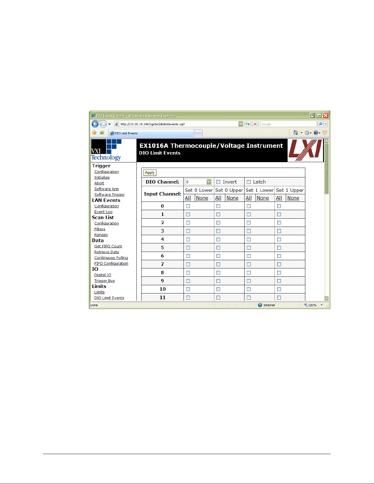
VTI Instruments Corp.
84 EX10xxA Web Page Operation
DIO limit events are programmable on a per channel basis; that is, each of the 8 DIO channels can
be configured with a unique set of operational characteristics. Only one DIO channel’s limit event
controls is displayed at a time on the page. Navigation between the DIO channels is provided by the
DIO Channel control, a pull-down selection.
The linkage of a DIO channel to a specific limit condition on a specific input channel is done by
checking the appropriate checkbox. Multiple selections are allowed and are logically OR’ed
together. For example, Figure 5-5 shows that DIO channel 0 is linked to limit conditions on input
channels 0, 3, and 5. Specifically, DIO channel 0 will transition if any of the four specified limits is
exceeded.
FIGURE 5-5: DIO LIMIT EVENTS PAGE
To ease data entry in complex configurations, the All and None links can be used to enable or disable
a limit set value across all input channels. It should be noted that the use of these links does not
eliminate the need to click the Apply button to accept the changes.
The DIO limit events and the scan list configuration controls are autonomous. That is, specifying a
limit condition in DIO Limit Events does not automatically enable it in the scan list. Similarly,
removing an input channel from the scan list does not automatically remove it as a linked limit
condition. DIO limit event linkages to unscanned channels do not cause an error condition and are
simply ignored in the evaluation.
Page 85

www.vtiinstruments.com
EX10xxA Web Page Operation 85
When linked as a limit event, a DIO channel will be cleared at the beginning of a new acquisition.
Its state will then be updated with each scan according to the programmed limit evaluations. By
default, the cleared state is low, but can be set on a per channel basis to be high through the selection
of the Invert checkbox. Similarly, the default operation for each channel is non-latch mode, but can
be set on a per channel basis to be latch mode through the selection of the Latch checkbox. In latch
mode, a transition out of the cleared state would remain, regardless of future limit evaluations, until
it is cleared at the beginning of a new acquisition.
DEVICE MENU
The Device menu is used to perform advanced configuration operations on the EX10xxA/E.
Self-calibration
This action page is used to perform operations related to self-calibration. As discussed in
Self-calibration in Section 3, the measurement performance of the EX10xxA is significantly
improved through the periodic use of self-calibration. The self-calibration process completes
quickly and does not require removal of the actual input connections or the use of external
equipment, making it convenient to run often. In order to take full advantage of the self-calibration
system, it is important to understand how the self-calibration constants are generated, used, and
stored.
Self-calibration does not overwrite, modify, or take the place of the instrument’s nonvolatile
calibration constants generated by a full calibration. Instead, it generates an additional set of
calibration constants that are applied to the measurement calculation after the full calibration
constants. When self-calibration is performed, it places its calculated data in volatile memory. This
data is termed the “current self cal data” and is used automatically by the instrument. No additional
command is necessary. Because it is in volatile memory, however, it will be cleared upon an
instrument reset or power cycle. There is the ability, however, to store the current self cal data into
nonvolatile memory.
In order to perform a self-calibration, a lock on the instrument must first be acquired. For more
information on locking, refer to the Locking Menu description in this section. If self-calibration is
attempted without the acquisition of a lock, an error message will be displayed. Within this page,
the self-calibration process is initiated by clicking on the Perform Self Calibration button. Once
started, the page will confirm the initiation of the calibration process and then continuously refresh
with a percentage completion status until completed. Once the completion status reaches 100%, the
self-calibration process is complete.
To protect the user from performing a self-calibration while the instrument is warming up, a warning
message will be issued and calibration will not be performed if self-calibration is attempted before
the EX10xxA has been powered on continuously for 60 minutes. This is only a warning, however,
and it can be overridden with the Override Self Calibration Uptime button that appears when this
warning is triggered. In general, this option should not be used, as performing self-calibration prior
to complete instrument warm-up could result in degraded measurement performance. However, it
would be appropriate to utilize the override in the case where the unit has actually been warmed up,
but has simply been subjected to a quick power cycle or reboot.
As noted above, the self-calibration operation places its calculated data in volatile memory, termed
“current self cal data.” Once present, it can be cleared by utilizing the Clear Current Self Cal Data
button. This operation clears the volatile data, but does not affect any self cal data that is stored in
nonvolatile memory.
Page 86

VTI Instruments Corp.
86 EX10xxA Web Page Operation
Despite having the ability to conduct self-calibration at any time, there may be user applications that
require the use of self-calibration, but demand that it create non-volatile data. The Store Current
Self Cal Data As Nonvolatile button saves the current self cal data to nonvolatile memory, enabling
it to be loaded upon instrument power cycle and reset. If this button is pressed when no current self
cal data is present, an error is generated. Since the existence of nonvolatile self cal data represents
a permanent (although revocable) change from the factory calibration settings, its presence is noted
on the EX10xxA Main and Self Calibration pages.
Previously saved nonvolatile self cal data can be cleared through the use of the Clear Nonvolatile
Self Cal Data button. This operation does not clear the current self cal data, only that in nonvolatile
memory. If this button is pressed when no nonvolatile self cal data is present, an error is generated.
Alternatively, previously saved nonvolatile self cal data can be loaded as the current self cal data
through the use of the Load Nonvolatile Self Cal Data button. If current self cal data previously
existed, it is simply overwritten and need not be cleared in advance. If this button is pressed when
no nonvolatile self cal data is present, an error is generated.
The ability to conduct a self-calibration is not affected by the existence of current self cal data or
nonvolatile self cal data. A performed self-calibration will simply overwrite any current self cal data
that already existed. It is not necessary to utilize the Clear Current Self Cal Data button prior to
performing a new self-calibration. Similarly, the ability to store current self cal data as nonvolatile
is not affected by the existence of previously saved nonvolatile data. The old data is simply
overwritten and need not be cleared in advance.
NOTE As part of the self-calibration process, the EX10xxA is reset, returning all configuration parameters
to their default values. This reset also clears all volatile self-calibration data.
NOTE EX1044 system requires hard reboot after self-calibration process so that instrument will be
calibrated values gets loaded upon reboot.
NOTE Self calibration is not applicable for RX10xx since during factory calibration process each
instrument will be calibrated in precise manner and calibrated data gets stored in the instrument
memory. The instrument has to be sent to factory to perform subsequent calibration after the initial
calibration date is expired Refer below section for Dynamic Calibration in RX1032
Dynamic Calibration in RX1032
The dynamic calibration should be conducted to calibrate the measurement drift due to the
temperature change. For every measurement scan, the values are adjusted based on the system
internal temperature.
The initial calculated Voltage and Temperature coefficients are stored into the RX1032
system.
At every measurement the measured values are calibrated dynamically using the stored
coefficients.
Based on the present temperature of the system, the values are calibrated and reported.
Get Calibration Files
This action page allows the user to download calibration data directly from the instrument. The
“Factory Calibration”, “Self Calibration”, and “Non-Volatile Self Calibration” links become active
after a calibration of that type has been performed. Once the link is clicked, an XML file will be
downloaded which contains the current calibration data for that type.
Page 87

www.vtiinstruments.com
EX10xxA Web Page Operation 87
Network Configuration
This entry page is used to change the network configuration of the EX10xxA. By default, the
EX10xxA will attempt to locate a DHCP server. If one is found, the IP address assigned by the
DHCP server will be assumed. Otherwise, after a timeout of 20 seconds, the unit will attempt to
obtain an IP address by using Auto IP.
Auto IP is a mechanism for finding an unused IP address in the range 169.254.X.Y where X is in
the range 1 through 254 and Y is in the range 0 through 255. The device will first attempt to obtain
the specific address 169.254.X.Y, where X and Y are the second-to-last and last octets of the
device’s MAC address. However, X will be set to 1 if it is 0 in the MAC address, and to 254 if it is
255 in the MAC address. If this address is already in use, the unit will attempt to obtain other IP
addresses in a pseudorandom fashion until it finds one that is available.
To illustrate the Auto IP mechanism, Table 5-2 lists the Auto IP default address for some example
MAC addresses.
MAC Address
Auto IP Default Address
00:0D:3F:01:00:01
169.254.1.1
00:0D:3F:01:01:01
169.254.1.1
00:0D:3F:01:A3:28
169.254.163.40
00:0D:3F:01:FE:FE
169.254.254.254
00:0D:3F:01:FF:FE
169.254.254.254
TABLE 5-2: AUTO IP DEFAULT ADDRESS ASSIGNMENT
If a static IP address assignment is preferred, one can be optionally assigned via this page. Click on
the Disabled radio button and then assign a static IP address. Following any changes, a Hard
Reboot must be conducted to activate them. The network configuration settings are stored in
nonvolatile memory and are unaffected by the Reset Device or Hard Reboot commands.
However, a much more convenient and recommended way to obtain the benefits of a static IP
address is to employ DHCP, but assign the instrument a reserved IP address in your company’s
DHCP server configuration. This reserved address, linked to the EX10xxA’s MAC address on the
DHCP server, would be assigned to the EX10xxA at power up initialization without having to
manually set it on the EX10xxA. The DHCP server configuration provides a centralized, controlled
database of assigned IP addresses, preventing accidental assignment of the same IP address to
multiple instruments. Consult your company’s Information Technology department for assistance.
VXI-11 Device Discovery is also supported by the EX10xxA. This allows all EX1048s on a local
network to be found without knowledge of their MAC address or IP address with the use of a
broadcast message.
Device Reset button
The device reset button on the rear panel of the EX10xxA can be used to restore default network
settings. This is useful for recovery from an incorrect or unknown network configuration. To
perform a network reset:
1) Power off the EX10xxA.
2) Press and hold the reset button.
3) Power on the EX10xxA.
4) Continue to hold the reset button for at least 30 seconds.
5) Release the reset button.
The EX10xxA will power up as usual, but will use the default network configuration (DHCP)
instead of its previous settings.
Page 88
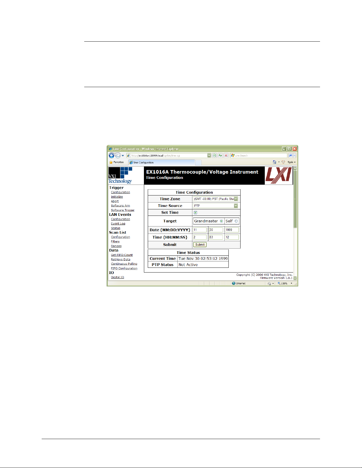
VTI Instruments Corp.
88 EX10xxA Web Page Operation
Device Identify
This action page provides the instrument’s identification information: the IP Address, Hostname,
MAC Address, and the status of the Indicator LED. By clicking the Identify button, the LAN LED
will flash green in order for the user can identify which instrument is being commanded. To return
the LED to its normal mode of operation, click on the Stop Identify button.
Time Configuration
This entry page is used to change the time configuration of the EX10xxA. As the EX10xxA has no
notion of “wall clock” or calendar time and no battery-backed clock or any other mechanism to
retain time between reboots and power-cycles, the time must be set by the user. By default, the
instrument’s time and date at power-up are midnight, January 1, 1999 (as defined by the
microcontroller). Three time source options are provided: PTP (Precision Time Protocol or
IEEE 1588 synchronization), SNTP (simple network time protocol), or manual. The default time
source is PTP.
FIGURE 5-6: TIME CONFIGURATION PAGE - PTP
Time Zone: allows the user to select an appropriate time zone.
Time Source: allows the user to set the EX10xxA’s date by entering the month (MM), day
(DD), and year (YYYY), respectively.
Set Time: for the PTP and Manual Time Source, allows the user to set the EX10xxA time
by entering the hour (HH), minute (MM), and second (SS), respectively. If the EX10xxA is
set as an IEEE 1588 Master, the hour should be entered using the 24-hour format.
NTP Servers: for the SNTP Time Source, allows the use to add/remove/save NTP servers to
which the EX10xxA will synchronize its time.
Time Status: this section of the web page provides the mainframe’s current time
configuration settings.
Using PTP Time
To configure the EX10xxA to use PTP time as the clock source:
1) Set Time Source to PTP. The page will change so that it can be configured.
2) Click Submit to start using PTP time.
Page 89
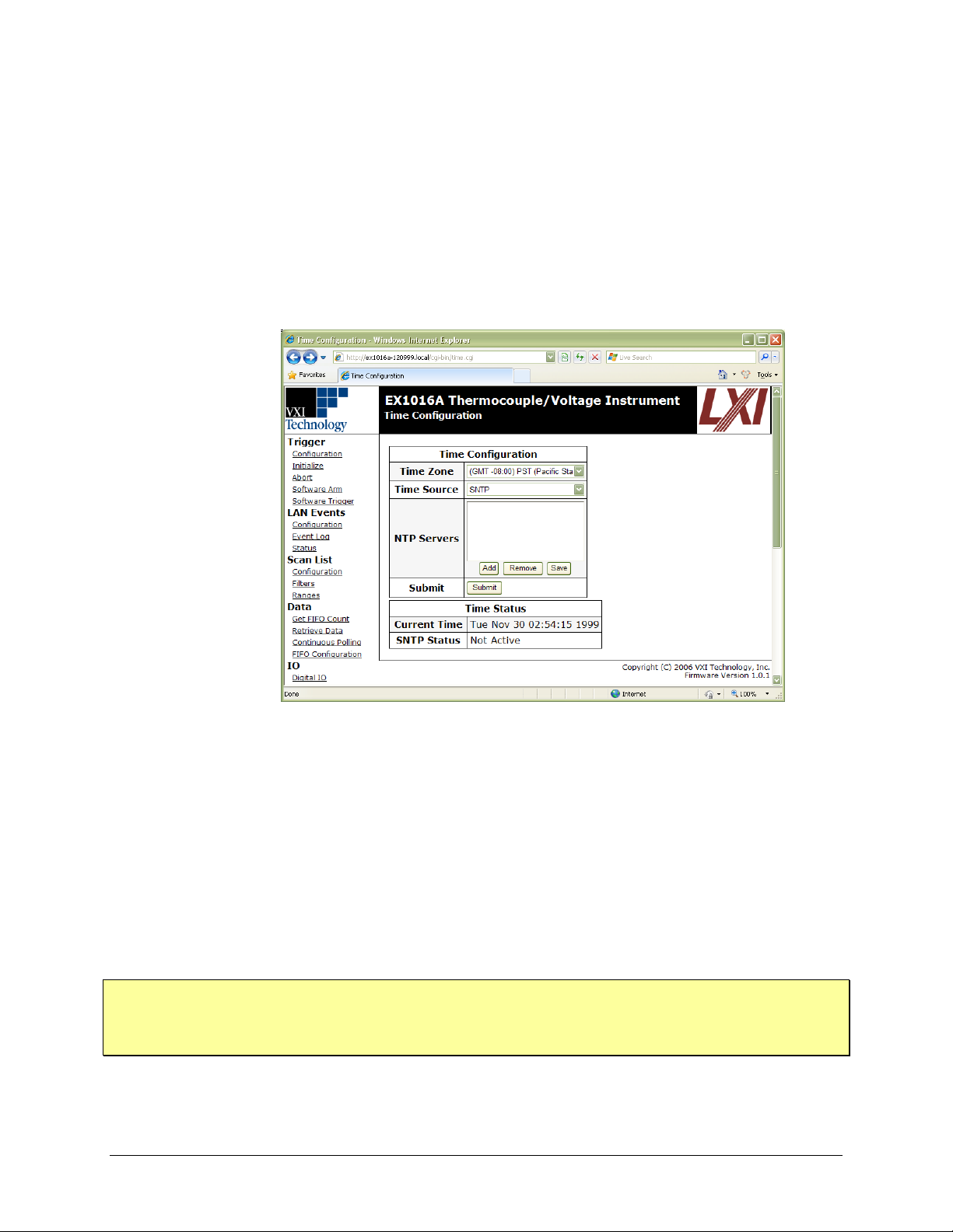
www.vtiinstruments.com
EX10xxA Web Page Operation 89
If a PTP master clock does not exist on the network, an LXI device on the network will begin serving
as the PTP time master. The Time Configuration page allows for PTP time to be set manually.
From the Time Configuration page, select the Set Time checkbox, then select the Grandmaster
radio button from the Target field, and then configure the time by hand. Note that the Time field
should be completed using a 24-hour format.
To use the EX10xxA as the PTP clock that will serve time on the LXI network, select the Self radio
button in the Target field. The EX10xxA then becomes the PTP master clock. While this ensures
measurement synchronicity between the units that to this clock, the overall timestamp accuracy is
not as accurate because of the time’s hand-set nature. For higher overall timestamp accuracy, use a
PTP master clock that is synchronized to a global time source like, such as GPS.
Using SNTP/NTP Time
FIGURE 5-7: TIME CONFIGURATION PAGE - SNTP
By selecting SNTP from the Time Source menu, the EX10xxA can be synchronized with an SNTP
server. The Time Zone drop menu allows the user to select the local time zone. SNTP, or NTP
(Network Time Protocol), servers are specified in the NTP Servers field, by IP address or hostname.
Once configured, the user must click Submit in order for the changes to take effect.
To configure the EX10xxA to use NTP time as its clock source:
1) Select SNTP from the Time Source field. The page will change so that it can be configured.
2) Add/Remove NTP servers use the appropriate buttons until the EX10xxA is configured to
communicate to the desired server(s).
3) Click the Save button to save the server configuration.
4) Click Submit to begin using NTP time.
NOTES 1) If the Submit button is clicked before saving an NTP configuration, the EX10xxA will start
using NTP time, but will use the last previously saved server configuration.
2) Specifying SNTP or NTP servers by hostname requires that the instrument has DNS, either by
DHCP or Static IP.
Page 90
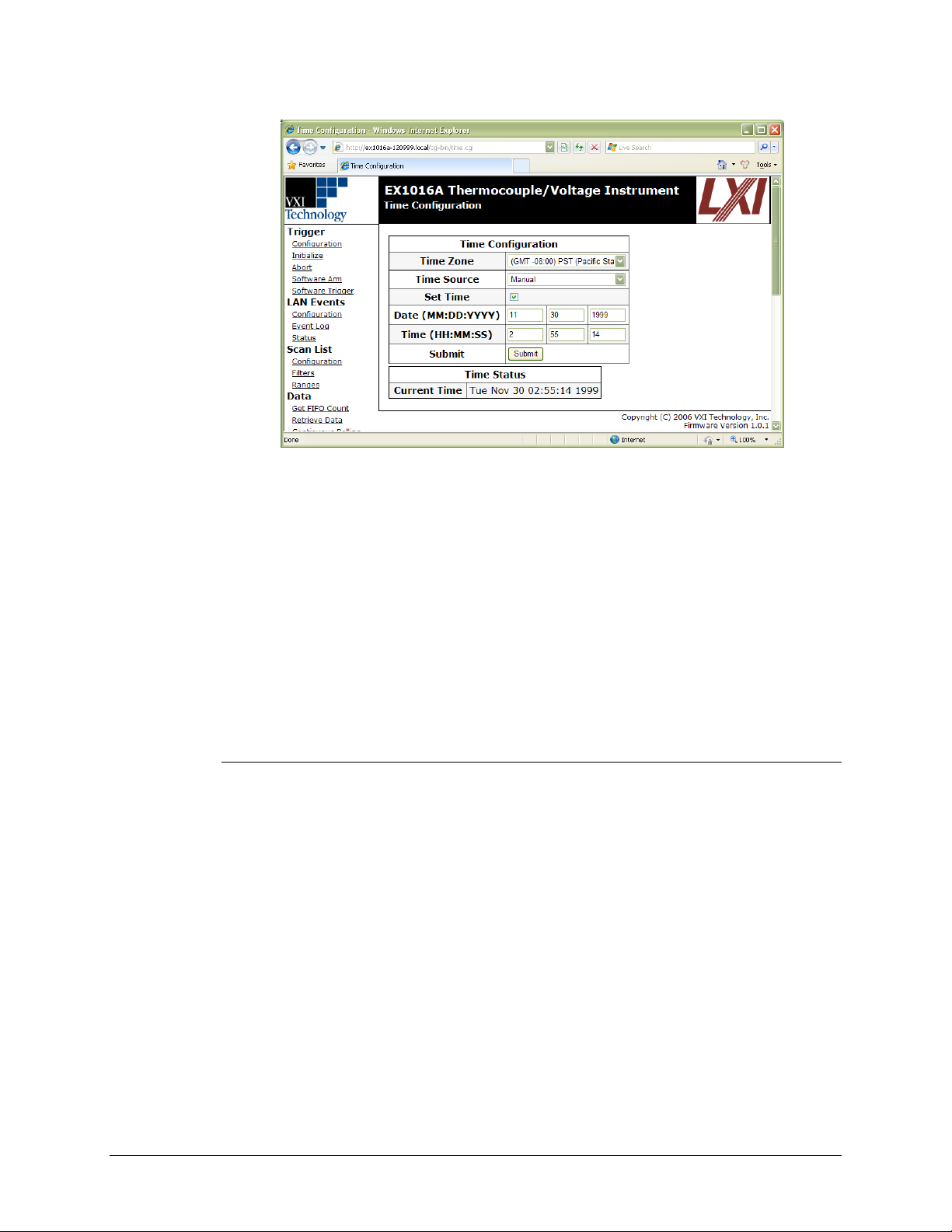
VTI Instruments Corp.
90 EX10xxA Web Page Operation
Using the Manual Time Setting
FIGURE 5-8: TIME CONFIGURATION PAGE - MANUAL
If a PTP master or an SNTP server is not available, time can be configured manually by the user by
selecting Manual in the Time Source drop menu. Note, manually set time sources are not very
accurate and that this configuration should only be used if timestamp accuracy is not vital to a
measurement.
To use a manually set time source:
1) Select Manual from the Time Source field. The page will change so that it can be
configured.
2) Select the Set Time checkbox.
3) Enter the required data into the Date and Time fields that appear. Note that the Time field
should be entered using the 24-hour format.
4) Click the Submit button to begin using the manual time source.
LXI Synchronization
This status page displays the EX10xxAs IEEE 1588 status. The PTP Grandmaster Clock MAC
field indicates the MAC address of the device on the network to which all other IEEE 1588
compliant devices are synchronized. The PTP Parent Clock MAC field identifies the MAC address
of the device to which the EX10xxA is synchronized. On a LAN that consists of multiple subnets,
this indicates the MAC address of the parent clock on that particular subnet. The PTP State field
shows the EX10xxA state: master, slave, faulty, disabled, passive, or unlocked.
Two types of wall clock time are available as well. The Current PTP Time field indicates the
number of seconds since midnight January 1, 1970 UTC (coordinated universal time). The local
time can be viewed by observing the Current Local Time field.
The Grandmaster Traceability to UTC indicates how the grandmaster is synchronized to the
UTC. The values provide an indicator of how closely synchronized the grandmaster is to UTC time
(see Table 5-3). The Domain field displays the instrument’s PTP subdomain. Typically, this
indicator is _DFLT. The final field, Wired-OR Bias, indicates whether the Wired-OR Bias for each
LXI trigger line (LXI0 through LXI7) is enabled or disabled.
Page 91
www.vtiinstruments.com
EX10xxA Web Page Operation 91
Value
Clock Source
UTC Synchronization
ATOM
UTC Atomic Clock
Less than 100 ns
GPS
GPS Receiver
Less than 100 ns
NTP
Network Time Protocol
Less than 50 ms
HAND
Manually/Automatically Set
Less than 10 s
INIT
User Defined
Not specified
DFLT
None
None
TABLE 5-3: UTC GRANDMASTER CLOCK IDENTIFIERS
Please note, the Current Variance of Parent field is not currently supported by the EX10xxA.
Reset Device
This action page is used to return all of the EX10xxA’s acquisition configuration parameters to their
default values. It is most commonly used to return the instrument to a known configuration state
prior to the initiation of a new test sequence. Specific affected configuration parameters and their
reset values are documented in Table 6-1. With regards to self-calibration data, an instrument reset
will clear the current self cal data and then load, if it exists, the nonvolatile self cal data as the current
self cal data. For more information on the generation and use of this data, refer to the
Self-calibration page description in this section.
NOTE An instrument reset clears the FIFO reading memory. All desired acquisition data must be retrieved
from the FIFO prior to the issuance of this command.
Hard Reboot
This action page is used to perform a complete instrument reboot, equivalent to that which occurs
when the instrument is power cycled. It is most commonly used to accept changes that are made to
the network configuration or time configuration settings. In addition, it is suggested that a reboot be
performed before conducting a firmware upgrade. Finally, it can be used to perform instrument
recovery if the unit is suspected to be in a failed firmware state.
Upgrade Firmware
This action page is used to upgrade the embedded firmware of the EX10xxA. Prior to initiating the
firmware upgrade process, a new, uncompressed firmware image must be obtained from
VTI Instruments and be accessible from the computer that is connected to the EX10xxA. Unless
specifically noted by VTI Instruments, firmware upgrades do not alter the calibration of the
EX10xxA.
NOTE Do not power cycle the EX10xxA during the firmware upgrade process. If power is lost during the
upgrade, the instrument may be put into an inoperable state, requiring return to the factory. An
uninterruptible power supply may be used to avoid this risk.
Perform the following steps to conduct a firmware upgrade:
1) Perform a Hard Reboot or a power cycle.
2) Connect to the EX10xxA via the embedded web page.
3) Click on the Upgrade Firmware link.
4) Click on the Proceed button.
5) Click on the Browse button and select the firmware image file to be uploaded to the instrument.
6) Click the Upload button to initiate the upgrade process.
NOTE Once the upgrade process is initiated, do not attempt to reconnect to the instrument. Wait until the
process is complete, as described below, before reconnecting.
Page 92

VTI Instruments Corp.
92 EX10xxA Web Page Operation
The process takes approximately 5 minutes to complete. Once the instrument has rebooted,
reconnect and confirm on the EX10xxA Main page that the firmware revision level has been
properly updated.
LOCKING MENU
The Locking menu is used to acquire, release, and break a lock on the EX10xxA’s acquisition
system.
Lock
This action page attempts to acquire a lock. It is good practice to lock the instrument whenever
protected operation is desired, but it is mandatory in order to perform self-calibration. If the
EX10xxA has been previously locked by another host, the lock will fail, and an error message will
be returned.
Unlock
This action page attempts to release a previously acquired lock. It will only release a lock that was
acquired by the same host. It will not release a lock acquired by a different host. In that case, the
unlock will fail, and an error message will be returned. An error message is also returned if the
unlock command is issued when the instrument is not in the locked state.
Break Lock
This action page breaks the lock on the EX10xxA, regardless of the host that originally acquired it.
It does not automatically acquire a lock in the same operation. If desired, that must be done with a
separate Lock command.
ADVANCED MENU
The Advanced menu is used to configure the EX10xxA to employ user-defined thermocouple
polynomial equations or utilize user-defined CJC temperatures. Neither of these functions is
required for normal operation with standard thermocouples.
User Conversions
This entry page is used to enter user-defined thermocouple polynomial coefficients. Up to two
unique sets of coefficients can be entered. For more details, see User-defined Conversions in
Section 3. The entry of user-defined coefficients does not automatically enable their use. The
enabling is done by setting the EU conversion to User0 or User1 in the Scan List…Configuration
page.
User CJC Temp
This entry page is used to enter and enable user-defined CJC temperatures. Each channel can be
associated with a unique value and be independently enabled with regards to its use. If enabled, the
user-defined CJC temperature will be used in the thermocouple calculations instead of the internally
measured one. The entry of external CJC values and their enabling are disjoint functions. That is,
the entry of a value does not automatically enable its use, and the disabling of a previously enabled
channel does not clear the value. All entries must be in units of ºC.
NOTE This feature must be used with care, as the input channel data contains no indication that it was
calculated with an external CJC value instead of an internal one.
Page 93

www.vtiinstruments.com
EX10xxA Web Page Operation 93
CONFIGURATION EXAMPLES
Example #1
This example demonstrates a typical setup sequence for a static monitoring application with an
alarm. The requirements of the application are:
Input connections are five type J thermocouples connected to channels 0-4 and five type K
thermocouples connected to channels 5-9.
The temperatures to be monitored are slow-moving, such that the 4 Hz filter frequency is
suitable.
Measurement data is required to be in units of ºF.
CJC temperature reporting is desired.
Data is to be acquired at a rate of 20 readings/second whenever DIO Channel 0 is high.
Once initiated, the test should continue until aborted.
DIO Channel 1 is to be used as an alarm indication, in which it needs to transition high and
stay high if any of the 10 input channels exceeds 100 ºF.
The exact steps to be performed to satisfy this application are:
Configure the Scan List
The scan list is configured with the Scan List…Configuration page. Click the Disabled link to
clear all previously enabled channels and then check the checkboxes of channels 0 through 9. With
the appropriate radio button, set the EU conversion of channels 0 through 4 to J and channels 5
through 9 to K. Click the Apply button to accept the changes.
Configure the Filter Frequencies
The filters are configured with the Scan List…Filters page. Click the 4 Hz radio button for channels
0 through 9. Alternatively, since all enabled channels require the same filter setting, the 4 Hz link
can be used to simultaneously set all channels. Click the Apply button to accept the changes.
Configure the FIFO
The FIFO is configured with the Data…FIFO Configuration page. Select the Temperature Units
selection of F. Check the Report CJC Temperatures checkbox. Click the Apply button to accept
the changes.
Configure the Trigger Model
The trigger model is configured with the Trigger…Configuration page. Click the Default button.
Expand the Arm branch to expose the Arm source. Deselect any currently checked sources. Expand
the Digital IO branch and select Pos. Level of DIO Channel 0. Within the Trig source, select Timer.
Enter a Timer Interval of 0.05. Check the Init Continuous checkbox. Click the Apply button to
accept the changes.
Configure the Limit System
Limit conditions are configured with the Limits…Limits page. Using the Set pull-down selection,
select Set: 0. For channels 0-9, check the Manual checkbox and enter an upper limit value of 100.
Click the Apply button to accept the changes. These limit conditions are linked to the DIO channel
through the Limits…DIO Limit Events page. Using the DIO Channel pull-down selection, select
DIO Channel: 1. Check the Set 0 Upper checkboxes for Input Channels 0-9. Check the Latch
checkbox. Click the Apply button to accept the changes.
Initiate the Trigger Model
The acquisition sequence is initiated with the Trigger…Initialize page.
Page 94

VTI Instruments Corp.
94 EX10xxA Web Page Operation
Example #2
This example demonstrates a typical setup sequence for a transient monitoring application with an
alarm. The requirements of the application are:
Input connections are 48 type E thermocouples connected to channels 0 through 47.
The temperatures to be monitored are transient in nature, such that the 1 kHz filter frequency
is suitable.
Measurement data is required to be in units of ºC.
Timestamp reporting is desired, but CJC temperature reporting is not.
Data is to be acquired at a rate of 1000 readings/second for 10 seconds, triggered by a positive
edge transition on channel 0 of the trigger bus.
Once the 10 seconds of data is collected, the test is complete.
DIO Channel 7 is to be used as an alarm indication, in which it needs to transition low if any
of the 48 channels exceeds 50 ºC.
The exact steps to be performed to satisfy this application are:
Configure the Scan List
The scan list is configured with the Scan List…Configuration page. Click the Enabled link to
enable all 48 channels. Since all channels require the same EU conversion, click the E link. Click
the Apply button to accept the changes.
Configure the Filter Frequencies
The filters are configured with the Scan List…Filters page. Since all channels require the same
filter setting, click the 1 kHz link. Click the Apply button to accept the changes.
Configure the FIFO
The FIFO is configured with the Data…FIFO Configuration page. Select the Temperature Units
selection of C. Uncheck the Report CJC Temperatures checkbox. Check the Report Timestamps
checkbox. Click the Apply button to accept the changes.
Configure the Trigger Model
The trigger model is configured with the Trigger…Configuration page. Click the Default button.
Expand the Arm branch to expose the Arm source. Deselect any currently checked sources. Expand
the VTI Trig. Bus branch and select Pos. Edge of VTB Channel 0. Within the Trig source, select
Timer. Set a TRIG Count of 10000. Enter a Timer Interval of 0.001. Uncheck the Init
Continuous checkbox. Click the Apply button to accept the changes.
Configure the Limit System
Limit conditions are configured with the Limits…Limits page. Using the Set pull-down selection,
select Set: 0. For channels 0-47, check the Manual checkbox and enter an upper limit value of 50.
Click the Apply button to accept the changes. These limit conditions are linked to the DIO channel
through the Limits…DIO Limit Events page. Using the DIO Channel pull-down selection, select
channel 7. Since all channels are required in the limit evaluation, click the Set 0 Upper All link.
Check the Invert checkbox. Uncheck the Latch checkbox. Click the Apply button to accept the
changes.
Initiate the Trigger Model
The acquisition sequence is initiated with the Trigger…Initialize page.
Page 95

www.vtiinstruments.com
EX10xxA Programming 95
SECTION 6
PROGRAMMING
PROGRAMMING SEQUENCE
The EX10xxA instrument driver is a VXI plug&play driver that is composed of top-level
C functions. The Figure 6-1 describes the typical steps performed in programming an acquisition
sequence on the EX10xxA. While the flow chart implies an order dependence to the functions, none
truly exists. Each function operates in a disjoint manner. The flow chart, however, does present a
logical flow of operations. For many applications, some of the detailed steps would not be required,
either because the default parameters are sufficient or the associated functionality is simply not
required.
Step 1
Configure the Scan List
Configure the EU Conversions
Configure the
Advanced Conversion Options
Configure the Filter Frequencies
Configure the FIFO
Configure the Limit System
Configure the Digital I/O System
Configure the Trigger Model
Initiate the Trigger Model
Step 2
Step 3
Step 4
Step 5
Step 6
Step 7
Step 8
Step 9
Retrieve Acquired Data
Trigger Event
Step 11
Configure the Trigger BusStep 10
FIGURE 6-1: PROGRAMMING SEQUENCE DIAGRAM
Page 96

VTI Instruments Corp.
96 EX10xxA Programming
DEFAULT SETTINGS
The default instrument settings after an instrument reset or a power cycle are listed in Table 6-1.
Many programming applications do not require parameter changes from the default settings and can
be made far simpler by the elimination of redundant commands. The EX10xxA can be returned to
the reset state at any time by calling the vtex10xxA_reset function.
TRIGGER CONFIGURATION RESET VALUES
CONFIGURATION PARAMETER
RESET VALUE
Init Continuous
Disabled
Timer Interval (seconds)
0.1
Arm Source
Immediate
Arm Count
1
Arm Delay (seconds)
0
Trig Source
Timer
Trig Count
1
Trig Delay (seconds)
0
SCAN LIST CONFIGURATION RESET VALUES
CONFIGURATION PARAMETER
RESET VALUE
Scan List (enabled channels)
0
EU Conversions
mV (voltage)
Filter (hertz)
4.0
FIFO CONFIGURATION RESET VALUES
CONFIGURATION PARAMETER
RESET VALUE
CJC Temperature Reporting
Disabled
Timestamp Reporting
Disabled
Temperature Units
C
Blocking Mode
Disabled
DIGITAL I/O CONFIGURATION RESET VALUES
CONFIGURATION PARAMETER
RESET VALUE
Output State
0
Output Enable
Disabled
TRIGGER BUS CONFIGURATION RESET VALUES
CONFIGURATION PARAMETER
RESET VALUE
Output State
0
Output Enable
Disabled
LIMITS CONFIGURATION RESET VALUES
CONFIGURATION PARAMETER
RESET VALUE
Lower Limit of Limit Set 0
-0.066
Upper Limit of Limit Set 0
0.066
Limit Set 0, Manual
Disabled
Lower Limit of Limit Set 1
-1e+38
Upper Limit of Limit Set 1
1e+38
DIO Limit Events
Disabled
DIO Limit Events, Invert
Disabled
DIO Limit Events, Latch
Disabled
DEVICE CONFIGURATION RESET VALUES
CONFIGURATION PARAMETER
RESET VALUE
Current Self Cal Data
Cleared
Network Configuration
Unaffected
Time Configuration
Unaffected
Lock
Unaffected
TABLE 6-1: DEFAULT SETTINGS
Page 97

www.vtiinstruments.com
EX10xxA Programming 97
ADVANCED CONFIGURATION RESET VALUES
CONFIGURATION PARAMETER
RESET VALUE
User-defined Conversion Coefficients
0
User-defined CJC Temperatures (values)
0
User-defined CJC Temperatures (enable)
Disabled
TABLE 6-1 (CONTINUED): DEFAULT SETTINGS
EX10XXA BACKWARD COMPATIBILITY
If an EX10xxA will replace an EX1048 in a test station, the existing program can be easily modified
to work seamlessly with the EX10xxA. By replacing all references of “vtex1048” with “vtex10xxA”
and using the EX1048 rev 2 plug&play driver , the EX10xxA can utilize the existing code. Likewise,
user applications developed for the EX10xxA can function with the EX10xxA hardware by loading
existing EX10xxA firmware.
While EX10xxA plug&play driver is functionally compatible with the EX1048 driver, some notable
programming differences arise due to hardware/firmware difference. For example, if an application
utilizes the high-speed streaming interface, minor application modification are needed in order to
get the correct time stamps from EX10xxA products.
EX10xxA plug&play driver has “vtex10xxA” prefix, while EX1048 has “vtex1048” prefix.
The time stamp data obtained from high-speed, streaming interface shall have a unit of
nanoseconds (ns) with EX10xxA products while they are microseconds (µs) with EX1048.
The nanosecond time stamp is required by LXI Class A specification. Alternatively, the user
can use new vtex10xxA_enable_streaming_dataEx function with legacy_mode = TRUE to
obtain the microseconds time stamp. When the user uses the EX1048 rev 2 plug&play driver
with EX1048A, the time stamp will be returned in microseconds.
The ID string returned by will be “EX1048A”, “EX1032A”,”EX1016A” or “EX1000A”
instead of “EX1048”.
EX10xxA IVI-COM driver will have “VTEX10xxA” as an instrument specific interface
prefix, while EX1048 IVI-COM driver has “VxiTechEX1048”.
EX10xxA IVI-C driver API has “vtiex10xxA” as a function prefix while EX1048 IVI-C
driver has “vtiex1048” as function prefix.
The EX10xxA driver, however, does not support the EX1048.
GENERAL COMMANDS / QUERIES
These commands are used for general instrument setup and communication. Details on full
command syntax are provided in Section 6.
Initializing the device
The vtex10xxA_init function is used to establish communication with the EX10xxA and must be
performed before any other command. The key parameter of this function is the IP address of the
EX10xxA to which to connect. Also specified within this function are options to confirm the identity
of the connected instrument and to reset the instrument upon connecting. The output of this function
is the session handle assigned to the connection, which is a unique identifier necessary in all
subsequent communications. Consequently, sessions to multiple instruments can be opened within
the same application, each uniquely identified by their session handle.
The vtex10xxA_revision_query function is used to obtain the release revisions of the instrument
driver and the embedded firmware of the connected EX10xxA.
The vtex10xxA_close function is used to terminate an established communication link with the
EX10xxA and should be performed at the conclusion of the test application. Part of its execution is
the unlocking of the instrument, leaving it in the proper state for the next application.
Page 98
VTI Instruments Corp.
98 EX10xxA Programming
Resetting the device
The vtex10xxA_reset function is used to return all of the EX10xxA’s acquisition configuration
parameters to their default values. It is most commonly used to return the instrument to a known
configuration state prior to the initiation of a new test sequence. Specific affected configuration
parameters and their reset values are documented in Table 6-1. With regards to self-calibration data,
an instrument reset will clear the current self cal data and then load, if it exists, the nonvolatile self
cal data as the current self cal data. For more information on the generation and use of this data,
refer to the Performing Self-Calibration description in this section.
NOTE An instrument reset clears the FIFO reading memory. All desired acquisition data must be retrieved
from the FIFO prior to the issuance of this function.
Performing Self-Calibration
As discussed in Self-calibration in Section 3, the measurement performance of the EX10xxA is
significantly improved through the periodic use of self-calibration. The self-calibration process
completes quickly and does not require removal of the actual input connections or the use of external
equipment, making it convenient to run often. In order to take full advantage of the self-calibration
system, it is important to understand how the self-calibration constants are generated, used, and
stored.
Self-calibration does not overwrite, modify, or take the place of the instrument’s nonvolatile
calibration constants generated by a full calibration. Instead, it generates an additional set of
calibration constants that are applied to the measurement calculation after the full calibration
constants. When self-calibration is performed, it places its calculated data in volatile memory. This
data is termed the “current self cal data” and is used automatically by the instrument. No additional
function is necessary. Because it is in volatile memory, however, it will be cleared upon an
instrument reset or power cycle. There is the ability, however, to store the current self cal data into
nonvolatile memory.
In order to perform a self-calibration, a lock on the instrument must first be acquired. For more
information on locking, refer to the Acquiring a Lock description in this section. If self-calibration
is attempted without the acquisition of a lock, an error will be generated. The self-calibration process
is initiated with the vtex10xxA_self_cal_init function. Once started, its percentage completion
status is accessible through the vtex10xxA_self_cal_get_status query. Other than this status check,
additional instrument driver calls should not be performed during self-calibration. Once the
completion status reaches 100%, the self-calibration process is complete.
To protect the user from performing a self-calibration while the instrument is warming up, an error
will be generated and calibration will not be performed if self-calibration is attempted before the
EX10xxA has been powered on continuously for 60 minutes. This is only a warning, however, and
it can be overridden. In general, this option should not be used, as performing self-calibration prior
to complete instrument warm-up could result in degraded measurement performance. However, it
would be appropriate to utilize the override in the case where the unit has actually been warmed up,
but has simply been subjected to a quick power cycle or reboot. Details on the override mechanism
are provided in the vtex10xxA_self_cal_init function description in Section 6.
NOTE The self-calibration uptime requirement is in place to protect the measurement integrity of the
instrument and should only be overridden with caution. In order to ensure that the override is
intentional, it is strongly recommended that user intervention be required in the software application
to employ it.
As noted above, the self-calibration operation places its calculated data in volatile memory, termed
“current self cal data.” Once present, it can be cleared by utilizing the vtex10xxA_self_cal_clear
function. This operation clears the volatile data, but does not affect any self cal data that is stored in
nonvolatile memory.
Page 99

www.vtiinstruments.com
EX10xxA Programming 99
Despite having the ability to conduct self-calibration at any time, there may be user applications that
require the use of self-calibration, but demand that it create nonvolatile data. The
vtex10xxA_self_cal_store function saves the current self cal data to nonvolatile memory, enabling
it to be loaded upon instrument power cycle and reset. If this function is sent when no current self
cal data is present, an error is generated. Since the existence of nonvolatile self cal data represents
a permanent (although revocable) change from the factory calibration settings, its presence is able
to be ascertained with the vtex10xxA_self_cal_is_stored query.
Previously saved nonvolatile self cal data can be cleared through the use of the
vtex10xxA_self_cal_clear_stored function. This operation does not clear the current self cal data,
only that in nonvolatile memory. If this function is sent when no nonvolatile self cal data is present,
an error is generated. Alternatively, previously saved nonvolatile self cal data can be loaded as the
current self cal data through the use of the vtex10xxA_self_cal_load function. If current self cal
data previously existed, it is simply overwritten and need not be cleared in advance. If this function
is sent when no nonvolatile self cal data is present, an error is generated.
The ability to conduct a self-calibration is not affected by the existence of current self cal data or
nonvolatile self cal data. A performed self-calibration will simply overwrite any current self cal data
that already existed. It is not necessary to utilize the vtex10xxA_self_cal_clear function prior to
performing a new self-calibration. Similarly, the ability to store current self cal data as nonvolatile
is not affected by the existence of previously saved nonvolatile data. The old data is simply
overwritten and need not be cleared in advance.
NOTE As part of the self-calibration process, the EX10xxA is reset, returning all configuration parameters
to their default values.
NOTE Self calibration is not applicable for RX10xx since during factory calibration process each
instrument will be calibrated in precise manner and calibrated data gets stored in the instrument
memory. The instrument has to be sent to factory to perform subsequent calibration after the initial
calibration date is expired. Refer below section for RX1032 Dynamic Calibration
NOTE EX1044 system requires hard reboot after self-calibration process so that instrument will be
calibrated values gets loaded upon reboot.
Dynamic Calibration in RX1032
The dynamic calibration should be conducted to calibrate the measurement drift due to the
temperature change. For every measurement scan, the values are adjusted based on the system
internal temperature.
The initial calculated Voltage and Temperature coefficients are stored into the RX1032
system.
At every measurement the measured values are calibrated dynamically using the stored
coefficients.
Based on the present temperature of the system, the values are calibrated and reported.
Acquiring a Lock
By default, the EX10xxA allows unrestricted operation from multiple hosts. While this offers a high
level of user flexibility, there are instances where protected operation is desirable, if not required.
For these applications, the EX10xxA can be “locked,” meaning that it will accept functions from
only the host IP address that issued the vtex10xxA_lock function. With the EX10xxA in this mode,
other host connections that attempt functions will be denied. Self-calibration, in fact, requires the
acquisition of a lock prior to its initiation.
Page 100

VTI Instruments Corp.
100 EX10xxA Programming
Once a lock has been acquired, it is released with the vtex10xxA_unlock function. The lock status
is not affected by the vtex10xxA_reset function, and it cannot be used to release a lock.
By design, the locking mechanism is able to be overridden by a secondary host that issues a
vtex10xxA_break_lock function. Thus, the lock provides a warning to other users that the unit is
in a protected operation state, but not absolute security. This allows for instrument recovery if the
locking IP address would become disabled. Breaking a lock, however, does not automatically
acquire it. That must be done with a separate vtex10xxA_lock function.
The lock status of the instrument is queried with the vtex10xxA_check_lock query. The response
to the query not only indicates whether the unit is locked, but also if the lock is owned by the issuer
of the query.
CONFIGURE THE SCAN LIST
The scan list is defined with the vtex10xxA_set_scanlist function. The EX10xxA can be configured
to include from 1 to all 48 of its input channels in the scan list. A valid scan list consists of:
at least one channel
no more than 48 channels
no repeated channels
The channels in the scan list can be listed in any order, but will be scanned in numerical order when
the scan list is executed.
Example #1: This code block configures a five-channel scan of channels 0 through 4 in sequential
order.
ViInt32 channels[5] = { 0, 1, 2, 3, 4 };
vtex10xxA_set_scanlist(vi, channels, 5);
Example #2: This code block configures a five-channel scan of channels 0 through 4 in reverse
order.
ViInt32 channels[5] = { 4, 3, 2, 1, 0 };
vtex10xxA_set_scanlist(vi, channels, 5);
The current scan list is queried with the Vtex10xxA_get_scanlist function.
CONFIGURE THE EU CONVERSIONS
The EU conversion for each thermocouple channel is configured with the
vtex10xxA_set_channel_conversion function. A channel’s EU conversion can be configured
regardless of its inclusion in the scan list, and multiple channels can be assigned to a specific
conversion type within one function. However, each unique conversion type must be set with a
separate function.
Example: This code block configures channels 0 through 4 for thermocouple type E and channels 5
through 8 for thermocouple type T.
#define TYPE_E 0x04
#define TYPE_T 0x03
ViInt32 e_channels[5] = { 0, 1, 2, 3, 4 };
vtex10xxA_set_channel_conversion(vi, e_channels, 5, TYPE_E);
ViInt32 t_channels[4] = { 5, 6, 7, 8 };
vtex10xxA_set_channel_conversion(vi, t_channels, 4, TYPE_T);
The current EU conversion assignment for any channel is queried with the
vtex10xxA_get_channel_conversion query.
 Loading...