


User Guide
MCU-V Plus
MCU-8

1. Initial Setup of VTEL MCU-V
Note: The initial setup involves using the infrared remote controller to navigate
and enter information. After that the VTEL MCU-V is most easily accessed via
an Internet browser (Microsoft Internet Explorer required)
1. Plug in IR receiver
2. Plug in IP network
3. Plug in power adapter
4. Plug in a computer screen (after initial network setup, the monitor can be removed and
access to MCU will be remote via Internet browser)
5. Turn on power (red button)
5.
2.1.
4.3.
When setting up the network for the MCU the first time, you will use
the handheld controller. After the network (IP address) is established
for the VTEL MCU V, you can use your Internet browser to make
more convenient changes.
Use the center Menu button to bring up “Settings” then “Network”
then “System”.

1. Initial Setup of VTEL MCU-8
Note: The initial setup involves using the infrared remote controller to navigate
and enter information. After that the VTEL MCU-8 is most easily accessed via
an Internet browser (Microsoft Internet Explorer required)
1. Plug in IR receiver (two plugs)
2. Plug in IP network
3. Plug in power
4. Plug in a computer screen (after initial network setup, the monitor can be removed and
access to MCU will be remote via Internet browser)
5. Turn on power
4.
3.
1.
2.
When setting up the network for the MCU the first time, you will use
the handheld controller. After the network (IP address) is established
for the VTEL MCU-8, you can use your Internet browser to make
more convenient changes.
Use the center Menu button to bring up “Settings” then “Network”
then “System”.

2. Typical example of MCU operation
This is a typical display on an IPanel in a multipoint call via the MCU.
• On the right side of the screen there are three participants in this example (presented in 2x2 format).
There may be a total of five active interactive videoconferencing participants.
• There will be a black box in the display. This is a good place to move your local PIP window.
This permits you to have local camera control during the conference.
• Note: there is no remote camera control in a multipoint call. Each site is responsible for the optimum
position of their cameras.
• On the left portion of the screen is a PowerPoint presentation shared by one of the active participants.
This is the H.239 data sharing function.
• There is a yellow box around one of the participants. This means that person is currently talking.
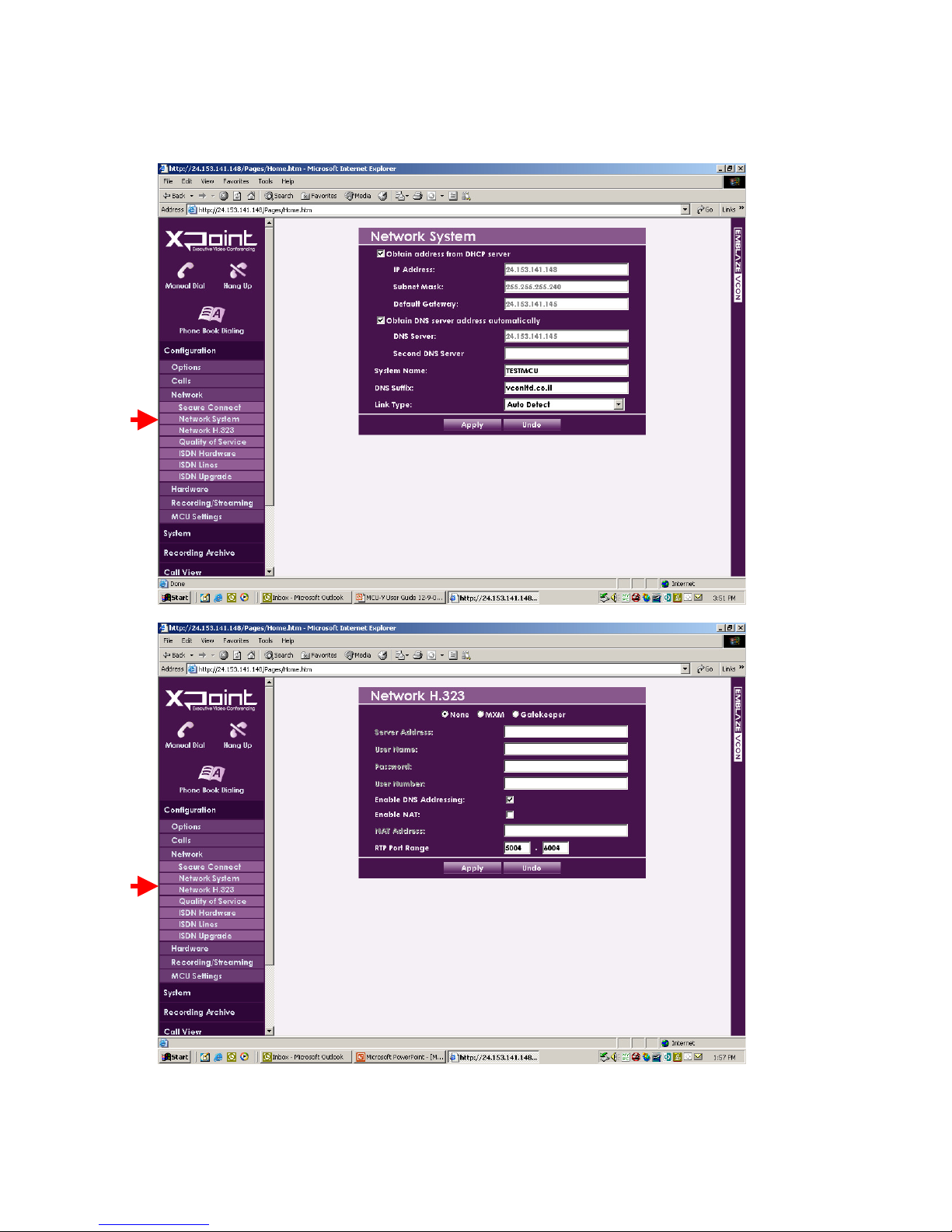
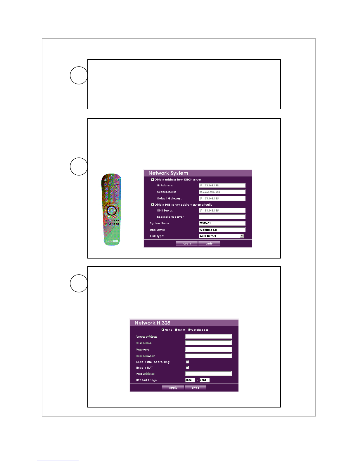
3. Network Settings
This is the screen shot via the Internet browser. It may
look different from the initial set of screens displayed
when using the handheld controller. At initial network
setup select “settings”, then “network”, then “system”.
Fill out the network settings.
Once the MCU network is established with
its IP address, you can access all the controls via
an Internet browser by http://(IP address)

4. Remote Operation of MCU
Once you have an IP address for the MCU, you
can use any Microsoft Internet Explorer browser
to gain live controls of the bridge.
Note: The
default
password is
blank.
Note: this is also the “home page” for any streaming viewer.
They would use their browser and go to the MCU (same IP
Address). Then, they would click on “View Stream”.
This is what a streaming viewer sees (example is of three active sites).
There is about a 12 second delay from live action to image/sound
presented on streaming sites.

5. MCU call control and display control
You can manually dial out to remote sites
or you can have them dial into the MCU
*These are the default recommended settings
Layout: (experiment with these settings while in a
test call with three to five endpoints)
Auto - MCU presents participant pictures
(recommended mode)
2X2 - Pictures are in four equal quadrants
5+1 - One large pane surrounded by smaller
panes
Answer Mode:
Accept All - any incoming call accepted
Manual* - Calls must be manually answered
from the MCU itself
Reject All - No incoming calls are accepted
Highlight Designated Speaker - there is a yellow
box around the speaker’s window
Names Overlay - Displays the remote site’s name
*Calls cannot be manually answered from the web interface,
you must have a display attached to the MCU and use its
remote control to accept the call!

6. Setup of Recording and Streaming
This is how you direct a
recording to the internal
hard disk in the MCU or
to an external USB
drive. This is where you limit the number
of streaming (passive viewing)
sites. The more streaming sites
permitted the more network
bandwidth required.
From the “Recording/Streaming” tab you can
start and stop streaming and recording

7. Recording and Streaming (continued)
Example: here the MCU is streaming and it is also
recording to its internal hard drive.
Going to the “recording archive” you can
see the all of the recordings on the MCU’s
hard drive. These are .wmv files.
Note: Select ‘All’ to display all recordings on
the MCU or select another option to filter the
results accordingly.

8. Moving Recording Files
You can copy a recording file and move it onto your
remote computer (the computer you’re using to control
the MCU via the Internet browser).
Just “right click” on the recording you want and then select
“save Target As…”
Now, select a location on your remote
computer to download the recording
from the MCU.
You can distribute the file to others as
an email attachment or to a public source
of information (.wmv file)

MCU Network Setup for Public Internet
• The MCU is designed to videoconference over the public Internet. If possible, it is recommended
that you assign the MCU a static IP address outside your firewall.
• This will only have to be done once at initial system installation.
• This decision tree flow chart covers all of the common network configuration conditions. Go to the
next page for the detailed step-by-step actions required (items A, B, and C)
Is there a
Firewall?
NO YES
Does network
A
use DHCP?
IPanel Settings
• IP Address
• Subnet Mask
• Default Gateway
• Preferred DNS Server
• Alternate DNS Server
Modem internal addresses
Source: ISP
B
Does network
use DHCP?
YESNO
YES NO
A
IPanel Settings
• IP Address
• Subnet Mask
• Default Gateway
• Preferred DNS Server
• Alternate DNS Server
Firewall internal addresses
Source: Network admin
Configure Firewall for Videoconferencing
• Open 1720 TCP port (incoming)
• Open 1718, 1719 UDP ports (incoming)
• Open 5004-6004 TCP and UDP ports
(outgoing/incoming)
B
OK
• Forward traffic to MCU
Does firewall do NAT?
YES
Enable NAT
on MCU
NO
C
MCU Network Setup for Public Internet
By default, your MCU is setup to use automatic IP detection (DHCP) on
its Ethernet port. If your internal network is configured to use DHCP
A
(which is the most common case) then simply plug a network cable into
the port on the MCU. You may will need to attach a monitor to the MCU
initially to verify/discover the IP address (in “Settings”-> ”Network”->
“System”).
• Once you have this information, ensure a monitor is attached to the
MCU and the remote is plugged in. Using the handheld, press the
center Menu button to bring up “Settings” then “Network” then
“System”.
• Use the handheld to fill out the IP information (see sections 1 and 3 of
this manual).
B
C
Bring up the MCU ’s Network H.323 settings (by going to Configuration>Network->Network {or IP} ->Network H.323). Check the "Enable NAT"
box and enter your public/external IP address in the “NAT Address” box
(you may have to ask your ISP/Network Administrator for this address).
Press “Apply" to apply the new settings.
 Loading...