

Page 1
MP252 Multimedia Home Gateway 13. Remote MP252 Management
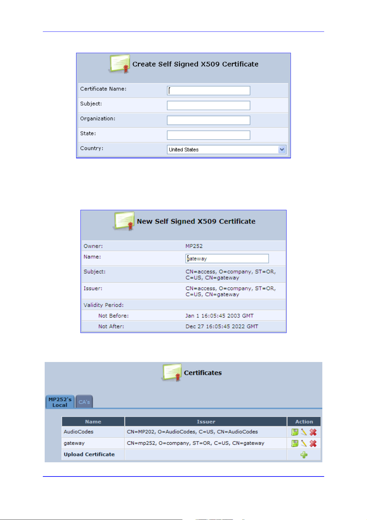
Figure 13-5: Create Self Signed X509 Certificate Screen
c. Enter the fields as required, and then click Generate; a message appears notifying
you that MP252 is generating the certificate.
d. After a few moments, click Refresh; the 'New Self Signed X509 Certificate' screen
appears.
Figure 13-6: New Self Signed X509 Certificate Screen
e. Click OK; the new certificate appears listed in the 'Certificates' screen.
Figure 13-7: Newly Created Self-Signed Certificate
Version 3.4.0 201 June 2011
Page 2
User's Manual
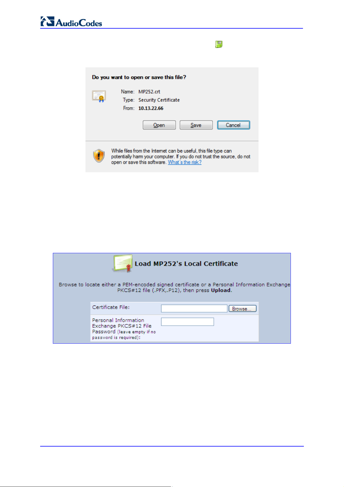
f. In the 'Certificates' screen, click the Download icon corresponding to the new
self-signed certificate that you created; the 'File Download' window appears.
Figure 13-8: File Download Window
g. Click Save, and then browse to the folder to where you want to save the file; the file
is saved as a *.crt file.
3. Configure the Apache server, by configuring the SSLCACertificateFile parameter to
point to the location where the certificate file is located. Since this is a self-signed
certificate, you are also considered the CA.
4. Load the self-signed certificate to MP252:
a. In the 'Certificates' screen, click the Upload Certificate link; the ‘Load MP252’s
Local Certificate’ screen appears.
Figure 13-9: Load MP252’s Local Certificate
b. Click Browse, locate the certification file that you created, and then click Upload to
load the file.
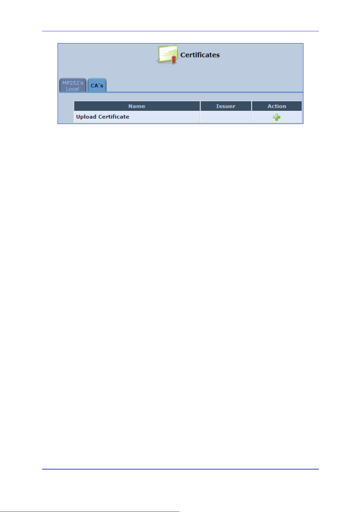
5. Load the CA’s certificate to MP252:
a. Select the CA’s tab; the ‘CA’s’ screen appears.
Figure 13-10: CA's Certificates Page
MP252 Multimedia Home Gateway 202 Document #: LTRT-23504
Page 3
MP252 Multimedia Home Gateway 13. Remote MP252 Management
Version 3.4.0 203 June 2011
Page 4
User's Manual
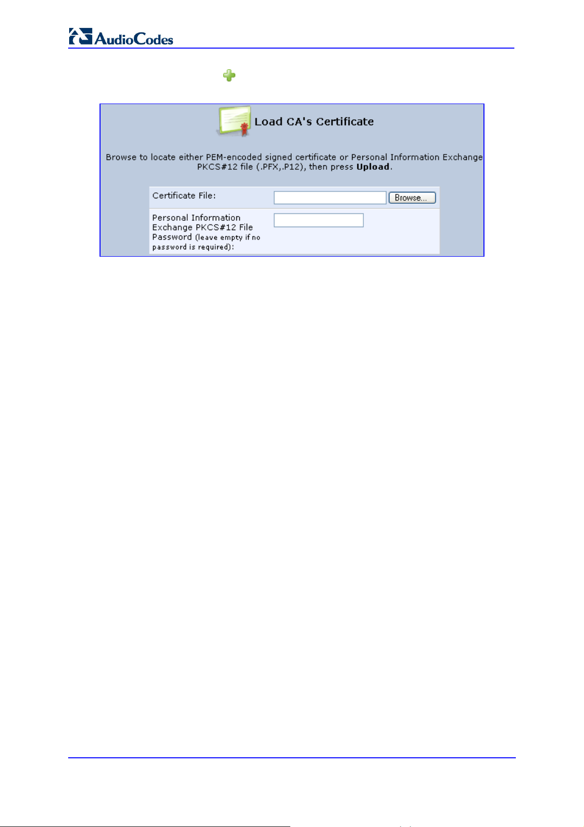
b. Click the New icon; the ‘Load CA’s Certificate’ screen appears.
Figure 13-11: Load CA's Certificate Page
c. Click Browse, locate the CA certification file that you created, and then click
Upload to load the file.
6. Configure the Apache server, using the following parameters:
• SSLCACertificateFile: Set the path to the CA’s certificate.
• SSLCertificateFile: Set the path to your signed certificate.
• SSLCertificateKeyFile: Set the path to your private key.
MP252 Multimedia Home Gateway 204 Document #: LTRT-23504
Page 5

MP252 Multimedia Home Gateway 13. Remote MP252 Management
13.4 Remote Configuration and Management Interfaces
MP252 supports the following remote configuration and management interfaces:
Web server (GUI) over HTTP/HTTPS
TR-069 and TR-104
SNMP
Syslog
Firmware or configuration file download through HTTP/HTTPS and FTP/TFTP
CLI over Telnet/SSH
The table below lists the possible operations over these different interfaces:
Table 13-5: Operations per Configuration/Management Interface
Operation Web GUI TR-069 SNMP Syslog File D/L CLI
Configuration Update
Firmware Upgrade
Status Monitoring
Debugging and
Diagnostics
Service providers can choose to combine several management interfaces, for example,
automatic file download for configuration and firmware updates plus SNMP for alarms.
Yes Yes Yes No Yes Yes
Yes Yes Yes No Yes Yes
Yes Yes Yes No No Yes
Yes No No Yes No Yes
13.4.1 Embedded Web Server
MP252 provides an embedded Web server with a rich Graphical User Interface (GUI). The
Web server can be accessed from the local LAN interface (e.g. by the home user) or from the
WAN interface (e.g. by the service provider support personnel). The Web GUI provides easy
and intuitive configuration of all MP252 parameters (i.e., VoIP, network interfaces, security,
QoS and advanced system settings). In addition, the Web GUI provides status monitoring
pages, diagnostic pages and enabled firmware upgrade.
Typically, service providers do not want to configure each MP252 manually and therefore,
they do not use the Web server in live deployments. However, the Web server is still useful
for:
Trying different configurations in the lab during the integration phases
Creating mass-configuration template files
Debugging special customer problems (by accessing the Web server from the WAN
interface)
Since the Web server allows all configuration and management operations, it is important to
protect it. The following security measures are available:
The Web server is user and password protected. Several users can be defined. A
special user with limited-access (only to the 'Quick Setup' screen) can be defined.
The access to the Web server can be blocked from the WAN and/or LAN interfaces.
Access to the Web server can be limited to specific IP addresses.
Secured HTTP (HTTPS) is supported. It is possible to enable HTTPS-only, if required.
Version 3.4.0 205 June 2011
Page 6
User's Manual
The HTTP and/or HTTPS port can be modified (from the default 80 and 8080).
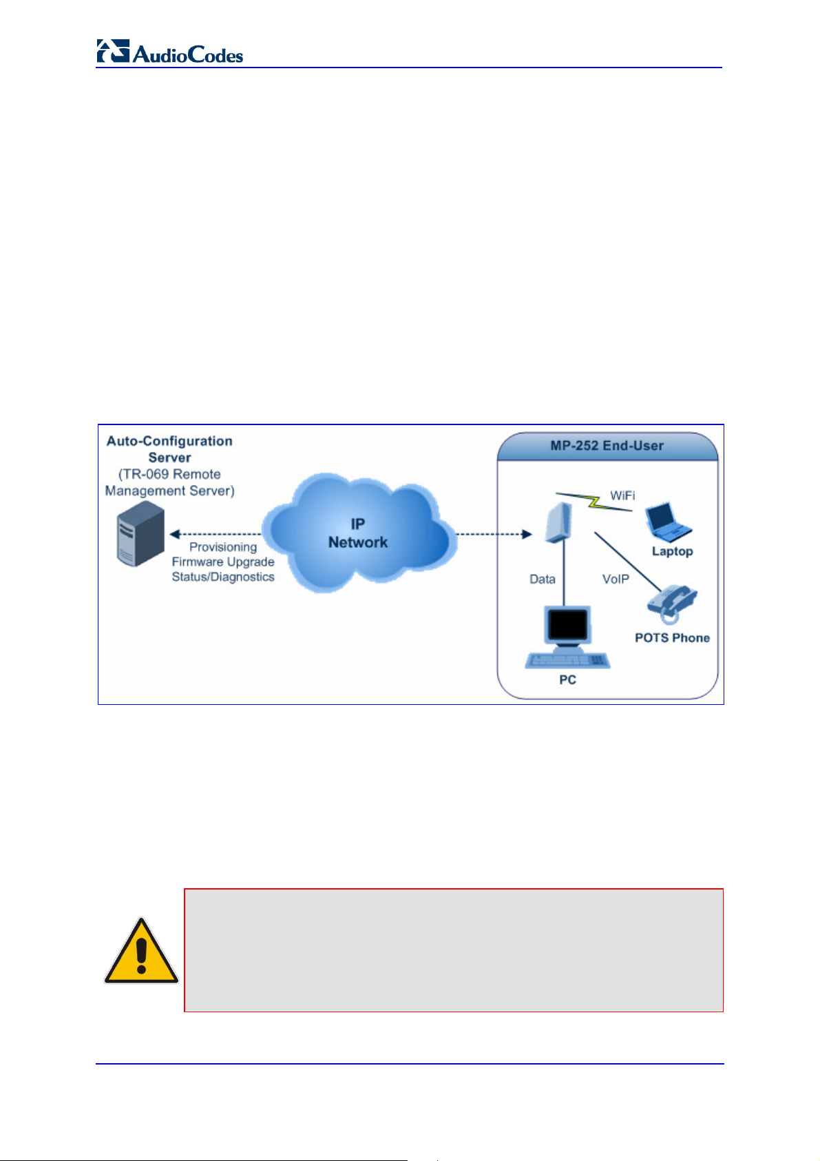
13.4.2 TR-069 and TR-104 CPE WAN Management Protocol
TR-069 is a WAN management protocol intended for communication between Customer
Premise Equipment (CPE) or residential devices (such as MP252), and an
Auto-Configuration Server (ACS), residing on the service provider's side. It defines a
mechanism that encompasses secure auto configuration of CPE, and also incorporates
other CPE management functions into a common framework. In simpler terms, TR-069 is a
protocol that enables remote server management of theMP252. Such a protocol is useful, for
example, for remotely and securely controlling MP252 by the CPE provider. The standard is
published by the DSL Forum. TR-069 runs over SOAP/HTTP and enables device
configuration, management (including firmware upgrade), and status monitoring. TR-104 is
an extension of TR-069 for VoIP configuration and monitoring.
The TR standards are published by the DSL forum:
TR-069: http://www.broadband-forum.org/technical/download/TR-069.pdf
TR-104: http://www.broadband-forum.org/technical/download/TR-104.pdf
Figure 13-12: TR-069 CPE WAN Management Protocol
The TR-069 protocol allows an ACS to provision a CPE or collection of CPE based on a
variety of criteria. The provisioning mechanism includes specific provisioning parameters
and a general mechanism for adding vendor-specific provisioning capabilities as needed.
The provisioning mechanism allows CPE provisioning at the time of initial connection to the
broadband access network, and the ability to re-provision at any subsequent time. This
includes support for asynchronous ACS-initiated re-provisioning of CPE. TR-069 defines
several Remote Procedure Call (RPC) methods, as well as a large number of parameters,
which may be set or read. Some of these methods and parameters are defined as
mandatory.
Notes:
• MP252 was tested for interoperability with two ACS vendors – Motive and
FriendlyTR69. Working with other ACS types may require specific
interoperability effort.
• The parameter values in the subsequent tables are sample values only
taken from an ACS.
MP252 Multimedia Home Gateway 206 Document #: LTRT-23504
Page 7

MP252 Multimedia Home Gateway 13. Remote MP252 Management
The method used to assign an address to the
The IP address of the default gateway for this
On creation of a WANIPConnection instance,
13.4.2.1 Configuring MP252 via TR-069 and TR-104
TR-069 allows basic configuration of MP252. The configuration is defined in a hierarchical
13.4.2.1.1 Configuring the WAN Interface
Table 13-6: InternetGatewayDevice.WANDevice.i.WANConnectionDevice.i.WANIPConnection.i
tree-like structure according to the TR-069 standard.
TR-069/TR-104
Parameter
Configuration File
Parameter
AddressingType mt_cwmp_param_wan_con
n_ip_addressing_type_get/
set
ConnectionStatus mt_cwmp_param_wan_con
n_ip_status_get
ConnectionType mt_cwmp_param_wan_con
n_ppp_type_get
Description
WAN side interface of the CPE for this
connection:
“DHCP”
“Static”
Current status of the connection:
“Unconfigured”
“Connecting”
“Connected”
“PendingDisconnect”
“Disconneting”
“Disconnected”
Specifies the connection type of the
connection instance:
“Unconfigured”
“IP_Routed”
“DHCP_Spoofed”
“PPPoE_Bridged”
“PPPoE_Relay”
“PPTP_Relay”
“L2TP_Relay”
DefaultGateway mt_cwmp_param_wan_con
n_ip_default_gateway_get/
set
DNSEnabled mt_cwmp_param_wan_con
n_ip_dns_enabled_get/set
DNSOverrideAllowed mt_cwmp_param_wan_con
n_ip_dnsoverrideallowed_
get/set
DNSServers mt_cwmp_param_wan_con
n_xxx_dnsservers_get/set(
i)
Enable mt_cwmp_param_wan_con
connection. This parameter is configurable
only if the AddressingType is Static.
Whether or not the device should attempt to
query a DNS server across this connection.
Whether or not a manually set, non-empty
DNS address can be overridden by a DNS
entry received from the WAN.
Comma-separated list of DNS server IP
addresses for this connection. Support for
more than three DNS Servers is optional.
Enables or disables the connection instance.
n_xxx_enable_get/set(1)
it is initially disabled.
ExternalIPAddress mt_cwmp_param_wan_con
n_xxx_externalip_get(i)
The external IP address used by NAT for this
connection. This parameter is configurable
only if the AddressingType is Static.
Version 3.4.0 207 June 2011
Page 8

User's Manual
PortMappingNumberOf
separated list indicating the types of
If less than or equal to 100, in percentages of
TR-069/TR-104
Parameter
Configuration File
Parameter
MaxMTUSize mt_cwmp_param_wan_con
n_ip_max_mtu_size_get/se
t( i)
Name mt_cwmp_param_wan_con
n_xxx_name_get/set(i)
NATEnabled mt_cwmp_param_wan_con
n_xxx_nat_enabled_get/set
(i )
-
Entries
PossibleConnectionTy
-
pes
RouteProtocolRx mt_cwmp_param_wan_con
n_xxx_route_protocol_rx_
get/set
Description
The maximum allowed size of an Ethernet
frame from LAN-side devices.
User-readable name of this connection.
Indicates if NAT is enabled for this connection.
Total number of port mapping entries.
A commaconnections possible for this connection
instance. Each element of the list is an
enumeration of:
“Unconfigured”
“IP_Routed”
“IP_Bridged”
Defines the Rx protocol to be used:
“Off”
“RIPv1” (Optional)
“RIPv2” (Optional)
“OSPF” (Optional)
RSIPAvailable mt_cwmp_param_wan_con
n_xxx_rsip_available_get(i)
ShapingRate -
SubnetMask lan_host_config_managem
ent_get/set
rg_conf dhcps/ netmask
SpecVersion “”
Uptime -
13.4.2.1.2 Configuring the LAN Interface
Indicates if Realm-specific IP (RSIP) is
available as a feature on MP252.
Rate to shape this connection’s egress traffic
to.
the rate of the highest rate-constrained layer
over which the packet travels on egress. The
rate is limited over the window period
specified by ShapeWindow.
If greater than 100, in bits per second.
A value of -1 indicates no shaping.
Subnet mask of the WAN interface. This
parameter is configurable only if the
AddressingType is Static.
Currently, 1.0 is the only available version.
The time in seconds that this connection has
been up.
Table 13-7: InternetGatewayDevice.LANDevice.i.LANEthernetInterfaceConfig
MP252 Multimedia Home Gateway 208 Document #: LTRT-23504
Page 9

MP252 Multimedia Home Gateway 13. Remote MP252 Management
TR-069/TR-104
Parameter
Configuration File
Parameter
Enable device_eic_enable_get/set
MACAddress device_mac_address_get
MaxBitRate device_max_bit_rate_get
Status device_status_get
Description
Enables or disables this interface.
The physical address of the interface.
The maximum upstream and downstream
bit rate available for this connection:
“10”
“100”
“1000”
“Auto”
The status of the interface:
“Up”
“NoLink”
“Error”
“Disabled”
Version 3.4.0 209 June 2011
Page 10

User's Manual
Table 13-8: InternetGatewayDevice.LANDevice.i.LANHostConfigManagement
TR-069/TR-104
Parameter
AllowedMACAddres
ses
Configuration File
Parameter
allowed_mac_addresses_g
et/set
DHCPLeaseTime dhcp_lease_time_get/set
DHCPRelay dhcp_relay_get/set
DHCPServerEnable lan_host_config_managem
ent_get/set
rg_conf dhcps/enable
DNSServers dhcps_dns_servers_get/se
t
DomainName domain_name_get/set
Description
Represents a comma-separated list of
hardware addresses that are allowed to
connect to this connection if
MACAddressControlEnabled is 1 for a
given interface.
Specifies the lease time in seconds of client
assigned addresses. A value of -1
indicates an infinite lease.
Determines if the DHCP server performs
the role of a server (0) or a relay (1) on the
LAN interface.
Enables or disables the DHCP server on
the LAN interface.
Comma-separated list of DNS servers
offered to DHCP clients. Support for more
than three DNS Servers is optional.
Sets the domain name for clients on the
LAN interface.
IPRouters ip_routers_get/set
MaxAddress lan_host_config_managem
ent_get/set
rg_conf dhcps/end_ip
MinAddress lan_host_config_managem
ent_get/set
rg_conf dhcps/start_ip
SubnetMask lan_host_config_managem
ent_get/set
rg_conf dhcps/ netmask
Comma-separated list of IP addresses of
routers on this subnet. Also known as
default gateway. Support for more than one
Router address is optional.
Specifies the last address in the pool to be
assigned by the DHCP server on the LAN
interface.
Specifies the first address in the pool to be
assigned by the DHCP server on the LAN
interface.
Specifies the client’s network subnet mask.
MP252 Multimedia Home Gateway 210 Document #: LTRT-23504
Page 11

MP252 Multimedia Home Gateway 13. Remote MP252 Management
13.4.2.1.3 Configuring VoIP via TR-104
Table 13-9: InternetGatewayDevice.Services.VoiceService.i.Capabilities
TR-069/TR-104
Parameter
ButtonMap
DSCPCoupled
EthernetTaggingCou
pled
FaxPassThrough
Configuration File
Parameter
- Support for a configurable button map. A true
value indicates support for a configurable
button map via the
VoiceService.{i}.VoiceProfile.{i}.ButtonMap
object.
- A true value indicates that the CPE is
constrained such that transmitted call control
packets use the same DSCP marking as
transmitted RTP packets.
If the value is true, the CPE must not support
the DSCPMark parameter for call control.
- A true value indicates that the CPE is
constrained such that transmitted call control
packets use the same Ethernet tagging (VLAN
ID Ethernet Priority) as transmitted RTP
packets.
If the value is true, the CPE must not support
the VLANIDMark or EthernetPriorityMark
parameters within a call control object (e.g.,
SIP, MGCP, or H323).
- Support for fax pass-through. A true value
indicates support for the parameter
VoiceService.{i}.VoiceProfile.{i}.FaxPassThro
ugh. (True if
voip/audio/fax/fax_transport_mode equals
Bypass)
Description
FaxT38
MaxLineCount voip/num_of_fxs_lines
MaxProfileCount
MaxSessionCount
MaxSessionsPerLin
e
Version 3.4.0 211 June 2011
- Support for T.38 fax. A true value indicates
support for the object
VoiceService.{i}.VoiceProfile.{i}.FaxT38.
Maximum number of lines supported across all
profiles.
- Maximum number of distinct voice profiles
supported.
- Maximum number of voice sessions supported
across all lines and profiles. (This might differ
from MaxLineCount if each line can support
more than one session for CPE provided
conference calling. This value can be less than
the product of MaxLineCount and
MaxSessionsPerLine.)
- Maximum number of voice sessions supported
for any given line across all profiles. A value
greater than one indicates support for CPE
provided conference calling.
Page 12

User's Manual
TR-069/TR-104
Parameter
ModemPassThrough
NumberingPlan
PSTNSoftSwitchOve
Configuration File
Parameter
- Support for modem pass-through. A true value
- Support for a configurable numbering plan. A
- A true value indicates MP252 is capable of
r
Regions pkg\mgt\lib\mgt_regiona
l_settings.c
slic_dsp_general_and_r
egional_settings_param
s_array
Description
indicates support for the parameter
VoiceService.{i}.VoiceProfile.{i}.ModemPassT
hrough.
true value indicates support for a configurable
numbering plan via the
VoiceService.{i}.VoiceProfile.{i}.NumberingPla
n object.
supporting the PSO_Activate Facility Action,
which allows a call to be switched to a PSTN
FXO.
Note: Currently, this parameter is not
supported.
Comma-separated list of geographic regions
supported by MP252. Each item in the list
must be an alpha-2 (two-character alphabetic)
country code as specified by ISO 3166.
An empty list indicates that MP252 does not
support region-based customization.
Note: This format is currently not supported.
RingGeneration
RTCP
RTPRedundancy
- Support for ring generation. A true value
- Support for RTCP.
- Support for RTP payload redundancy as
SignalingProtocols voip/signalling/protocol
indicates support for control of ring generation
via the
VoiceService.{i}.VoiceProfile.{i}.Line.{i}.Ringer
object.
A true value also indicates that the
RingDescriptionsEditable,
PatternBasedRingGeneration and
FileBasedRingGeneration parameters in this
object are present.
defined in RFC 2198. A true value indicates
support for
VoiceService.{i}.VoiceProfile.{i}.RTP.Redunda
ncy.
Signal protocol:
“SIP”
“MGCP”
Each entry can be appended with a version
indicator in the form “/X.Y”. For example:
“SIP/2.0”.
Note: Only one protocol is supported at a time.
SRTP
- Support for SRTP.
Note: Currently, SRTP is not supported.
MP252 Multimedia Home Gateway 212 Document #: LTRT-23504
Page 13

MP252 Multimedia Home Gateway 13. Remote MP252 Management
TR-069/TR-104
Parameter
ToneGeneration
VoicePortTests
Configuration File
Parameter
- Support for tone generation. A true value
- Support for remotely accessible voice-port
Table 13-10: InternetGatewayDevice.Services.VoiceService.i.Capabilities.Codecs
TR-069/TR-104
Parameter
Configuration File
Parameter
Codec voip/codec/i/name
EntryID voip/codec/i/
Description
indicates support for the object
VoiceService.{i}.VoiceProfile.{i}.Tone.
A true value also indicates that the
ToneDescriptionsEditable,
PatternBasedToneGeneration and
FileBasedToneGeneration parameters in this
object are present.
tests. A true value indicates support for the
VoiceService.{i}.PhyInterface.{i}.Tests object.
Description
Identifier of the type of codec.
Unique identifier for each entry in the table.
PacketizationPeriod voip/codec/i/ptime
Comma-separated list of supported
packetization periods (in milliseconds), or
continuous ranges of packetization periods.
Ranges are indicated as a hyphen-separated
pair of unsigned integers.
For example:
“20” indicates a single discrete value.
“10, 20, 30” indicates a set of discrete
values.
“5-40” indicates a continuous inclusive
range.
“5-10, 20, 30” indicates a continuous
range in addition to a set of discrete
values.
A range must only be indicated if all values
within the range are supported.
Note: Currently, only a single ptime per
codec is supported.
Version 3.4.0 213 June 2011
Page 14

User's Manual
Table 13-11: InternetGatewayDevice.Services.VoiceService.i.VoiceProfile
TR-069/TR-104
Parameter
Configuration File
Parameter
DTMFMethod voip/out_of_band_dtmf
Enable
Name
- Enables or disables all lines in this profile, or
- String to easily identify the profile instance.
Description
Method by which DTMF digits must be
passed:
“InBand”
“RFC2833”
“SIPInfo
places it into a quiescent state:
“Disabled”
“Quiescent”
“Enabled”
On creation, a profile must be in the Disabled
state.
In the Quiescent state, in-progress sessions
remain intact, but no new sessions are
allowed. Support for the Quiescent state in a
MP252 is optional. If this parameter is set to
“Quiescent” in a MP252 that does not support
the Quiescent state, it must treat it the same
as the Disabled state.
Note: Currently, this is not supported.
NumberOfLines voip/num_of_fxs_lines
Table 13-12: InternetGatewayDevice.Services.VoiceService.i.VoiceProfile.i.SIP
TR-069/TR-104
Parameter
Configuration File
Parameter
OutboundProxy voip/
signalling/sip/sip_outbou
nd_proxy/addr
Number of instances of Line within this
VoiceProfile.
Description
Host name or IP address of the outbound
proxy. If a non-empty value is specified, the
SIP endpoint must send all SIP traffic
(requests and responses) to the host
indicated by this parameter and the port
indicated by the OutboundProxyPort
parameter. This must be done regardless of
the routes discovered using normal SIP
operations, including use of Route headers
initialized from Service-Route and
Record-Route headers previously received.
The OutboundProxy value is not used to
generate the URI placed into the Route
header of any requests.
MP252 Multimedia Home Gateway 214 Document #: LTRT-23504
Page 15

MP252 Multimedia Home Gateway 13. Remote MP252 Management
TR-069/TR-104
Parameter
Configuration File
Parameter
OutboundProxyPort voip/
signalling/sip/sip_outbou
nd_proxy/proxy
ProxyServer voip/signalling/sip/proxy_
address
or
voip/signalling/sip/sip_re
gistrar/addr
ProxyServerPort voip/signalling/sip/proxy_
port
or
voip/signalling/sip/sip_re
gistrar/port
ProxyServerTranspo
rt
voip/signalling/sip/transp
ort_protocol
RegisterExpires voip/signalling/sip/proxy_
timeout
Description
Destination port for connecting to the
outbound proxy. This parameter must be
ignored unless the value of the
OutboundProxy parameter in this object is
non-empty.
Host name or IP address of the SIP proxy
server.
Destination port for connecting to the SIP
server.
Transport protocol for connecting to the SIP
server. Must be chosen from among the
transports supported.
Register request Expires header value (in
seconds).
RegistrarServerTran
sport
voip/signalling/sip/transp
ort_protocol
Transport protocol for connecting to the SIP
server. Must be chosen from among the
transports supported.
UserAgentPort voip/signalling/sip/port
UserAgentTransport voip/signalling/sip/transp
ort_protocol
Port for incoming call control signaling.
Transport protocol for incoming call control
signaling.
13.4.2.1.4 Upgrading Firmware via TR-069
TR-069 contains a built-in mechanism for MP252 firmware upgrade.
13.4.2.2 Monitoring MP252 Status via TR-069 and TR-104
13.4.2.2.1 Device Information
The service provider can monitor the status of MP252 via TR-069 and TR-104.
Table 13-13: InternetGatewayDevice.DeviceInfo
TR-069/TR-104
Parameter
Configuration File
Parameter
Description
Description manufacturer/description
DeviceLog “”
HardwareVersion Manufacturer/hardware/v
ersion
A full description of MP252 (string).
Vendor-specific log(s).
A string identifying the particular MP252
model and version.
Version 3.4.0 215 June 2011
Page 16

User's Manual
TR-069/TR-104
Parameter
Configuration File
Parameter
Manufacturer manufacturer/vendor_na
me
ManufacturerOUI manufacturer/vendor_oui
ModelName manufacturer/model_num
ber
ProductClass manufacturer/product_cla
ss
ProvisioningCode cwmp/provisioning_code
Description
A string identifying the manufacturer of
MP252, i.e., AudioCodes.
Organizationally unique identifier of the
device manufacturer. Represented as a six
hexadecimal-digit value using all upper-case
letters and including any leading zeros.
A string identifying the model name of
MP252.
Identifier of the class of product for which the
serial number applies. That is, for a given
manufacturer, this parameter is used to
identify the product or class of product over
which the SerialNumber parameter is unique.
Identifier of the primary service provider and
other provisioning information, which may be
used by the Server to determine service
provider-specific customization and
provisioning parameters.
If non-empty, this argument must be in the
form of a hierarchical descriptor with one or
more nodes specified. Each node in the
hierarchy is represented as a 4-character
sub-string, containing only numerals or
upper-case letters. If there is more than one
node indicated, each node is separated by a
"." (dot). For example, “TLCO” and
“TLCO.GRP2”.
SerialNumber Manufacturer/hardware/s
erial_num
SoftwareVersion system/external_version
UpTime
- Time in seconds since MP252 was last reset.
Serial number of MP252.
A string identifying the software version
currently installed in MP252.
To allow version comparisons, this element
must be in the form of dot-delimited integers,
where each successive integer represents a
more minor category of variation. For
example, 3.0.21 where the components
mean Major.Minor.Build.
MP252 Multimedia Home Gateway 216 Document #: LTRT-23504
Page 17

MP252 Multimedia Home Gateway 13. Remote MP252 Management
13.4.2.2.2 WAN Status
Table 13-14: InternetGatewayDevice.WANDevice.i.WANConnectionDevice.i.
WANIPConnection.i.Stats
TR-069/TR-104
Parameter
EthernetBytesRecei
ved
Configuration File
Parameter
mt_cwmp_param_wan_co
nn_ip_stats_get
(STAT_RX_BYTES)
EthernetBytesSent mt_cwmp_param_wan_co
nn_ppp_stats_get
( STAT_TX_BYTES)
EthernetPacketsRec
eived
mt_cwmp_param_wan_co
nn_ppp_stats_get
( STAT_RX_PACKETS)
EthernetPacketsSent mt_cwmp_param_wan_co
nn_ppp_stats_get
13.4.2.2.3 LAN Status
Description
Total number of bytes received over all
connections within the same
WANConnectionDevice that share a common
MAC address since MP252 was last reset.
Total number of bytes sent over all
connections within the same
WANConnectionDevice that share a common
MAC address since MP252 was last reset.
Total number of Ethernet packets received
over all connections within the same
WANConnectionDevice that share a common
MAC address since MP252 was last reset.
Total number of Ethernet packets sent over
all connections within the same
WANConnectionDevice that share a common
MAC address since MP252 was last reset.
Table 13-15: InternetGatewayDevice.LANDevice.i.LANEthernetInterfaceConfig.i.Stats
TR-069/TR-104
Parameter
BytesReceived mt_voip_get_state (line,
BytesSent mt_voip_get_state(line,
PacketsReceived mt_voip_get_state(line,
PacketsSent mt_voip_get_state(line,
Configuration File
Parameter
state)
state)
state)
state)
Description
Total number of bytes received over the
interface since MP252 was last reset.
Total number of bytes sent over the interface
since MP252 was last reset.
Total number of packets received over the
interface since MP252 was last reset.
Total number of packets sent over the
interface since MP252 was last reset.
Version 3.4.0 217 June 2011
Page 18

User's Manual
13.4.2.2.4 VoIP Status via TR-104
Table 13-16: InternetGatewayDevice.Services.VoiceService.i.VoiceProfile.i.Line.i.Stats
TR-069/TR-104
Parameter
ResetStatistics
PacketsSent mt_voip_get_state(line,
PacketsReceived mt_voip_get_state(line,
BytesSent mt_voip_get_state(line,
BytesReceived mt_voip_get_state(line,
PacketsLost mt_voip_get_state(line,
Overruns
Underruns
IncomingCallsReceive
d
Configuration File
Parameter
- When set to one, it resets the statistics for
state)
state)
state)
state)
state)
- Total number of times the receive jitter buffer
- Total number of times the receive jitter buffer
-
Description
this voice line. Always False when read.
Total number of RTP packets sent for this
line.
Total number of RTP packets received for
this line.
Total number of RTP payload bytes sent for
this line.
Total number of RTP payload bytes received
for this line.
Total number of RTP packets that have been
lost for this line.
has overrun for this line.
has underrun for this line.
Total incoming calls received.
IncomingCallsAnswere
d
IncomingCallsConnect
ed
IncomingCallsFailed
OutgoingCallsAttempt
ed
OutgoingCallsAnswere
d
OutgoingCallsConnect
ed
OutgoingCallsFailed
CallsDropped
TotalCallTime
ServerDownTime
- Total incoming calls answered by the local
user.
- Total incoming calls that successfully
completed call setup signaling.
- Total incoming calls that failed to successfully
complete call setup signaling.
-
- Total outgoing calls answered by the called
- Total outgoing calls that successfully
- Total outgoing calls that failed to successfully
- Total calls that were successfully connected
- Cumulative call duration (in seconds).
- The number of seconds MP252 is unable to
Total outgoing calls attempted.
party.
completed call setup signaling.
complete call setup signaling.
(incoming or outgoing), but dropped
unexpectedly while in progress without
explicit user termination.
maintain a connection to the server. Applies
only to SIP.
MP252 Multimedia Home Gateway 218 Document #: LTRT-23504
Page 19

MP252 Multimedia Home Gateway 13. Remote MP252 Management
TR-069/TR-104
Parameter
Configuration File
Parameter
ReceivePacketLossRate mt_voip_get_state(line,
state)
FarEndPacketLossRat
- Current far-end receive packet lost rate (in
e
ReceiveInterarrivalJitte
- Current receive interarrival jitter (in
r
FarEndInterarrivalJitte
- Current Interarrival jitter (in microseconds) as
r
RoundTripDelay mt_voip_get_state
AverageReceiveInterar
- Average receive interarrival jitter (in
rivalJitter
AverageFarEndInterarr
- Average far-end interarrival jitter (in
ivalJitter
AverageRoundTripDel
- Average round-trip delay (in microseconds)
ay
Description
Current receive packet loss rate (in
percentage).
percentage).
microseconds).
reported from the far-end device via RTCP.
Current round-trip delay (in microseconds).
microseconds) since the beginning of the
current call.
microseconds) since the beginning of the
current call.
since the beginning of the current call. This is
the average of the RoundTripDelay statistics
accumulated each time the delay is
calculated.
13.4.2.3 Security Concerns and Measures
The CPE WAN Management Protocol is designed to allow a high degree of security in the
interactions that use it. The CPE WAN Management Protocol is designed to prevent
tampering with the transactions that take place between a CPE and ACS, provide
confidentiality for these transactions, and allow various levels of authentication.
The following security mechanisms are incorporated in this protocol:
The protocol supports the use of SSL/TLS for communications transport between CPE
and ACS. This provides transaction confidentiality, data integrity, and allows
certificate-based authentication between the CPE and ACS.
The HTTP layer provides an alternative means of CPE authentication based on shared
secrets.
Version 3.4.0 219 June 2011
Page 20
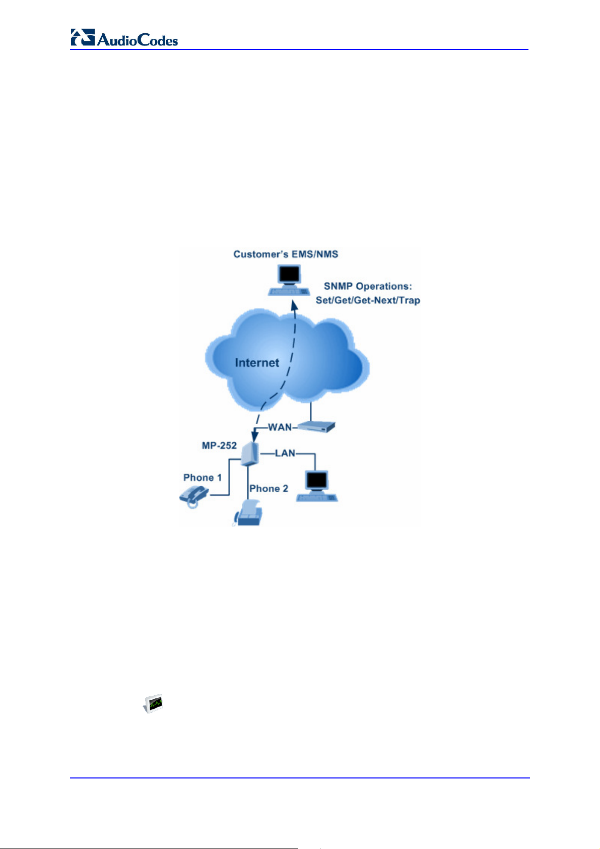
13.4.3 SNMP
Simple Network Management Protocol (SNMP) is used in network management systems to
configure and monitor network-attached devices. SNMP is an IETF standard defined by RFC
1157, 1441 and additional RFCs for specific Management Information Base (MIBs).
MP252 contains an embedded SNMP agent and supports SNMPv1, SNMPv2 and partially
supports SNMPv3. For monitoring of the network interfaces, the standard SNMP MIB-II
(RFC 1213) is supported. For more options, a proprietary MIB, AC-MP20X-MIB includes the
following sections:
acMP20xConfig: for changing MP252's configuration
acMP20xStatus: for monitoring MP252's status
The figure below shows the SNMP network architecture:
User's Manual
Figure 13-13: SNMP Network Architecture
13.4.3.1 Enabling SNMP in the Web Interface
Simple Network Management Protocol (SNMP) enables Network Management Systems
(NMSs) to remotely configure and monitor your MP252. Your ISP may use SNMP to identify
and resolve technical problems. Technical information regarding the properties of MP252's
SNMP agent should be provided by your ISP.
The procedure below describes how to configure the SNMP agent embedded on
the MP252.
To configure MP252's SNMP agent:
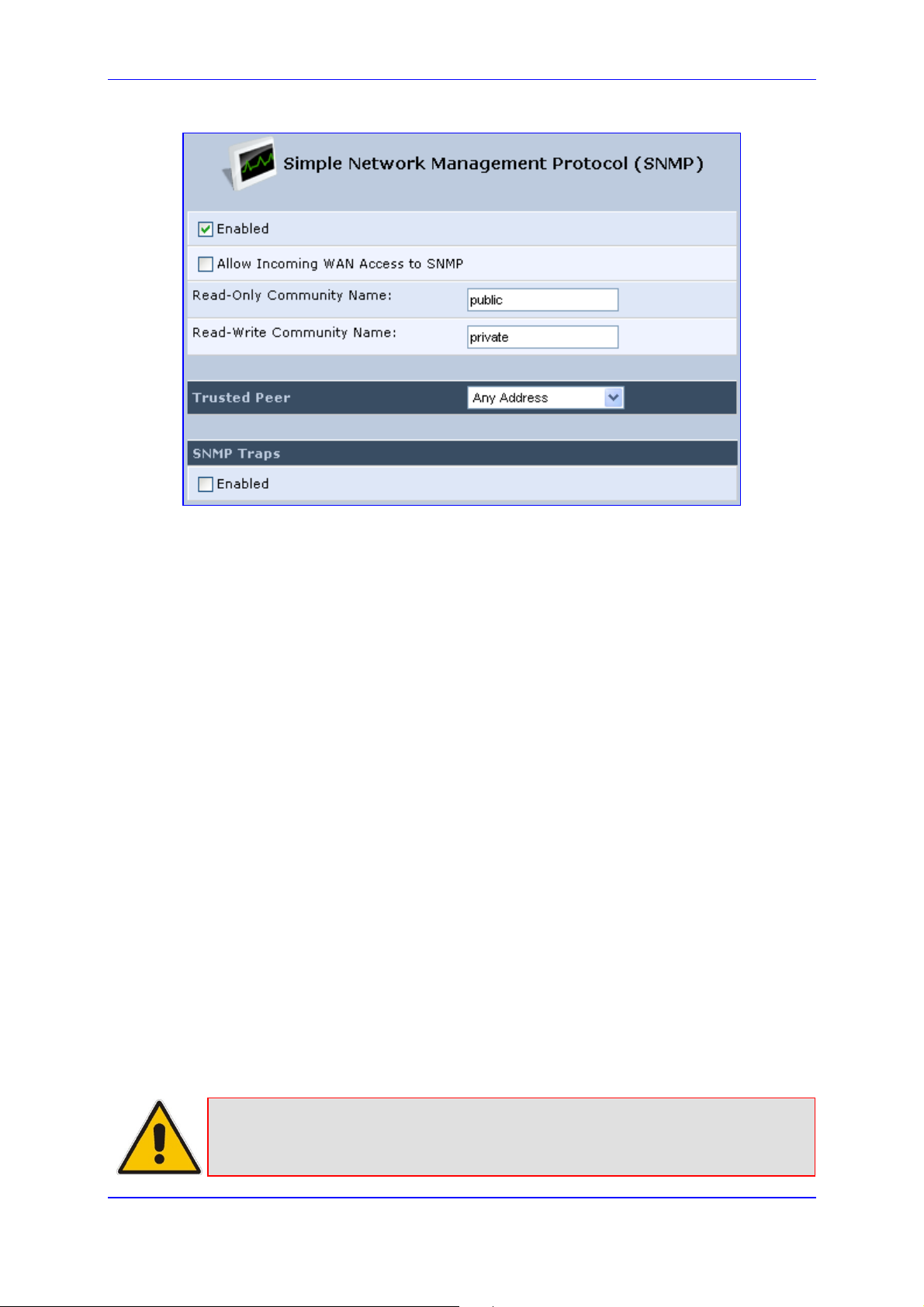
1. In the 'Advanced' screen, click the Simple Network Management Protocol (SNMP)
icon; the 'Simple Network Management Protocol (SNMP)' screen appears.
MP252 Multimedia Home Gateway 220 Document #: LTRT-23504
Page 21
MP252 Multimedia Home Gateway 13. Remote MP252 Management
Figure 13-14: Simple Network Management Protocol (SNMP) Screen
2. Select the 'Enabled' check box to enable SNMP.
3. Select the ‘Allow Incoming WAN Access to SNMP’ check box to allow access to
MP252's SNMP agent over the Internet.
4. In the ‘Read-Only Community Names’ and ‘Read-Write Community Names’
fields, enter the SNMP community strings. These strings are passwords used in SNMP
messages between the management system and MP252. A read-only community
allows the manager to monitor MP252. A read-write community allows the manager to
monitor and configure MP252.
5. From the ‘Trusted Pair’ drop-down list, enter the IP address, or subnet of addresses that
identify which remote management stations are allowed to perform SNMP operations
on MP252.
6. Under the SNMP Traps group, select the ‘Enabled’ check box to allow MP252 to send
messages (traps) to a remote management station to notify the manager about the
occurrence of important events or serious conditions.
• Version: SNMP version - SNMP v1 or SNMP v2c traps.
• Destination: remote management station's IP address.
• Community: community name that is associated with the trap messages.
7. Click OK to save your settings.
13.4.3.2 Configuring MP252 via SNMP
The acMP20xConfig MIB section is structured in a similar hierarchy as MP252's Web GUI.
Each parameter in the MIB has a matching parameter in the Web GUI and a matching
parameter in the gateway’s configuration file. The MIB file defines the valid range and the
default value for each parameter. Typically, the customer integrates the MP20x MIB into the
customer's Network Management System (NMS) to automate the configuration process.
Note: A special MIB object is defined to allow MP252 firmware upgrade triggered by
SNMP. The object acMP20xRemoteUpdate triggers a remote upgrade from the
SNMP-configured URL.
Version 3.4.0 221 June 2011
Page 22

User's Manual
13.4.3.3 Status Monitoring of System and Network Interfaces via SNMP
SMNP can be used to monitor the status of MP252. Status monitoring of the system and
network interfaces can be done via the standard MIB-II
(iso(1).org(3).dod(6).internet(1).mgmt(2).mib-2(1)). The following table shows some of the
information elements available via MIB-II:
Table 13-17: Table 3-13: Information Elements Available via MIB-II
Section Available Information
system
interfaces Information per network interface:
Description
Version Information
Up-time
Description
Type
Speed
MAC address
Traffic statistics
Errors
ip
icmp, udp, tcp
ifMIB
Assigned IP addresses and IP-related parameters
Transport-protocol specific statistical information
Information about network interfaces per RFC 2233
13.4.3.4 Security Concerns and Measures
Since SNMP allows write-access to configuration parameters, it is important to protect this
interface. The following security measures are available:
A community string (password) can be defined for read-only access and for read/write
access.
It is possible to limit access to SNMP to a trusted peer (single IP address or a range of
addresses).
SNMPv3 provides an significant security improvement over SNMPv1/2. Version 2.8.0
will support SNMPv3 and will allow the service provider to configure SNMPv3 security
parameters.
SNMP traffic can be allowed over an IPSec secured connection – check availability with
AudioCodes.
MP252 Multimedia Home Gateway 222 Document #: LTRT-23504
Page 23

MP252 Multimedia Home Gateway 13. Remote MP252 Management
13.4.4 Syslog
Syslog is a standard protocol for reporting and logging of messages over IP network and is
defined by RFC 3164. MP252 enables the service provider to configure a Syslog server and
a severity level above which errors are sent to the server. Typically, only error-level
messages should be sent to the Syslog server (in order not to flood it with irrelevant
debug-level information). For debugging, it is possible to temporarily allow logging for
debug-level messages (e.g. for SIP messages).
Many free Syslog servers exist, including Kiwi Syslog Daemon' (http://www.kiwisyslog.co'm
http://www.kiwisyslog.com).
Note: Since Syslog is used only to output messages from MP252, it does not contain
any security concerns.
13.4.5 Automatic File Download
A practical, straight-forward and easy to implement method for mass configuration and
firmware update is automatic file download from a remote file server (via HTTP, FTP, or
TFTP). This method is used by many service providers.
13.4.5.1 Firmware File Download
MP252's firmware files contain information about the target product type and the firmware
version information.
13.4.5.2 Configuration File Download
MP252 supports two configuration file formats, a *.conf file and an *.ini file. Both files define
the same parameters, but in a different format; the *.conf file has a hierarchical tree-like
structure and the *.ini file is "flat" (defining the full path for each parameter).
As with the firmware file, the configuration file can be “pushed” to MP252 via the Web server
or “pulled” by MP252 from a remote server. This section refers only to the second option.
When MP252 downloads a file from a remote server, it performs the following actions:
Decrypts the file, if it is encrypted.
Checks that the file version is later than the current configuration file version (if it is not
later, the new configuration is not used).
Checks the software version with which the configuration file was created (if the file was
created with a later software version, it is not used).
Version 3.4.0 223 June 2011
Page 24

User's Manual
restored to factory settings, modify the required parameters using the Web
Merges the configuration file with the current configuration:
• Parameters that appear in the new file are modified or added
• Parameters that do not appear in the new file remain in their existing value
Notes:
• It is recommended that the configuration file (that is downloaded from the
network), contains only the small subset of parameters that the service
provider needs to update remotely.
• To create the configuration file, it is recommended to use a MP252 that is
GUI, and then upload the configuration file from MP252 with the option to
get only the modified configuration fields enabled.
13.4.5.3 Security Concerns and Measures
The main security hazard in automatic file download is that a hacker can force MP252 to
download a file from the hacker's server instead of the service provider’s legitimate server.
Another concern is exposing information such as the SIP proxy IP address and user and
password information in the configuration file (if the hacker is sniffing the network).
The following security measures are available to prevent this:
The configuration file can be encrypted using 3DES with pre-configured key. This
prevents the user from learning the format of the file and obtaining information from it.
HTTPS can be used to further encrypt the transport.
HTTPS certificates can be used to allow MP252 to authenticate the server and also to
prevent the user from acquiring the file from the server.
13.4.6 Telnet CLI
MP252 features a Command Line Interface (CLI) over Telnet. The CLI enables the service
provider to manage MP252 (e.g. reboot, force a firmware upgrade), to obtain information
about the status of the device (e.g. VoIP calls, network interfaces, version information), to
change the configuration and to perform different debugging tasks (e.g. enable debug
logging, enable packet recording).
Typically, the CLI interface is only used for debugging and diagnostics, since it does not
allow mass configuration and monitoring.
Since the CLI allows all configuration and management operations, it is important to protect it.
The following security measures are available:
The CLI is user and password protected (same as the Web).
Telnet access can be blocked from the WAN and/or LAN interfaces.
It is possible to limit Telnet access to specific IP addresses.
Future versions will support SSH.
MP252 Multimedia Home Gateway 224 Document #: LTRT-23504
Page 25
MP252 Multimedia Home Gateway 14. Security
14 Security
MP252's security suite includes comprehensive and robust security services: Stateful Packet
Inspection Firewall, user authentication protocols and password protection mechanisms.
These features together allow users to connect their computers to the Internet and
simultaneously be protected from the security threats of the Internet.
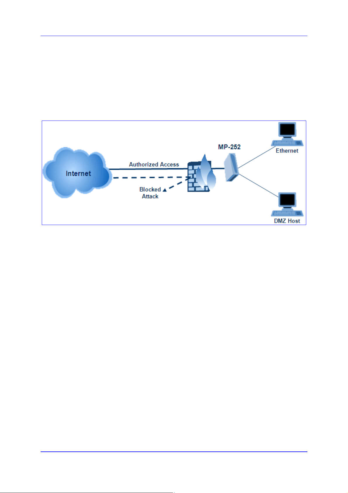
The firewall, which is the cornerstone of your MP252's security suite, has been exclusively
tailored to the needs of the residential/office user and has been pre-configured to provide
optimum security.
Figure 14-1: Firewall in Action
MP252 firewall provides both the security and flexibility that home and office users seek. It
provides a managed, professional level of network security while enabling the safe use of
interactive applications, such as Internet gaming and video-conferencing.
Additional features, including surfing restrictions and access control, can also be easily
configured locally by the user through a user-friendly Web-based interface, or remotely by a
service provider.
MP252 firewall supports advanced filtering, designed to allow comprehensive control over
the firewall's behavior. You can define specific input and output rules, control the order of
logically similar sets of rules and make a distinction between rules that apply to WAN and
LAN network devices.
The Web-based management screens in the Security section feature the following:
The 'General' screen allows you to choose the security level for the firewall (see'
General Security Level Settings' on page 226).
The 'Access Control' screen can be used to restrict access from the home network to
the Internet (see 'Local Servers (Port Forwarding)' on page 229).
The 'Port Forwarding' screen can be used to enable access from the Internet to
specified services provided by computers in the home network and special Internet
applications (see 'Port Forwarding' on page 229).
The 'DMZ Host' screen allows you to configure a LAN host to receive all traffic arriving at
your MP252, which does not belong to a known session (see' Port Triggering' on page
235).
The 'Port Triggering' screen allows you to define port triggering entries, to dynamically
open the firewall for some protocols or ports. (see 'Remote Administration' on page
261).
The 'Website Restrictions' allows you to block LAN access to a certain host or web site
on the Internet (see 'Website Restrictions' on page 237).
'Advanced Filtering' allows you to implicitly control the firewall setting and rules (see
'Advanced Filtering' on page 244).
Version 3.4.0 225 July 2011
Page 26
User's Manual
'Security Log' allows you to view and configure the firewall Log (see Security Log).
14.1 General Security Level Settings
Use the 'Security Settings' screen to configure the MP252's basic security settings.
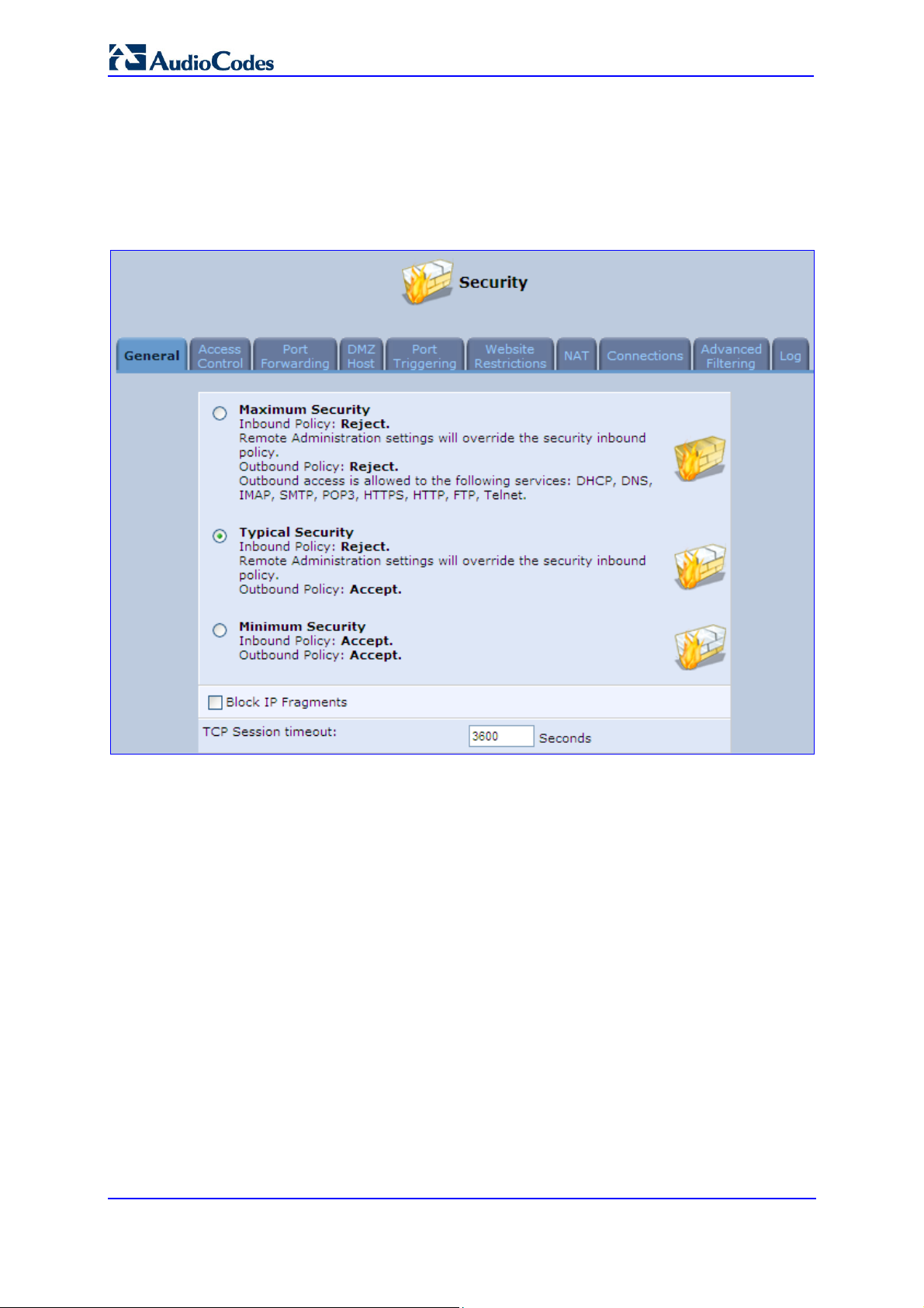
Figure 14-2: General Security Level Settings
The firewall regulates the flow of data between the home network and the Internet. Both
incoming and outgoing data are inspected and then either accepted (allowed to pass through
MP252) or rejected (barred from passing through MP252) according to a flexible and
configurable set of rules. These rules are designed to prevent unwanted intrusions from the
outside, while allowing home users access to the Internet services that they require.
The firewall rules specify what types of services available on the Internet may be accessed
from the home network and what types of services available in the home network may be
accessed from the Internet. Each request for a service that the firewall receives, whether
originating in the Internet or from a computer in the home network, is checked against the set
of firewall rules to determine whether the request should be allowed to pass through the
firewall. If the request is permitted to pass, then all subsequent data associated with this
request (a "session") are also allowed to pass, regardless of its direction.
For example, when you point your Web browser to a Web page on the Internet, a request is
sent out to the Internet for this page. When the request reaches MP252, the firewall identifies
the request type and origin--HTTP and a specific PC in your home network, in this case.
Unless you have configured access control to block requests of this type from this computer,
the firewall allows this request to pass out onto the Internet (see 'WAN PPPoE' on page 181
for more on setting access controls). When the Web page is returned from the Web server
the firewall associates it with this session and allows it to pass, regardless of whether HTTP
access from the Internet to the home network is blocked or permitted.
MP252 Multimedia Home Gateway 226 Document #: LTRT-23504
Page 27

MP252 Multimedia Home Gateway 14. Security
from Internet, except as configured in the
from Internet, except as configured in the
Note that it is the origin of the request, not subsequent responses to this request, that
determines whether a session can be established or not.
You can choose from among three pre-defined security levels for MP252: Minimum, Typical,
and Maximum (the default setting). The table below summarizes the behavior of MP252 for
each of the three security levels.
Table 14-1: Behavior for the Three Security Levels
Security Level
Maximum
Security
(Default)
Typical Security
Minimum
Security
These services include Telnet, FTP, HTTP, HTTPS, DNS, IMAP, POP3 and SMTP.
The list of allowed services at 'Maximum Security' mode can be edited in the screen' 'Access
Contro'l on page 228'.
Some applications (such as some Internet messengers and Peer-To-Peer client applications)
tend to use these ports if they cannot connect with their own default ports. When applying
this behaviour, these applications are not blocked outbound, even at Maximum Security
Level.
Requests Originating
in the WAN
(Incoming Traffic)
Blocked: No access to home network
Local Servers, DMZ host and Remote
Access screens
Blocked: No access to home network
Local Servers, DMZ host and Remote
Access screens
Unrestricted: Permits full access from
Internet to home network; all connection
attempts permitted.
Requests
Originating
in the LAN
(Outgoing Traffic)
Limited: Only commonly- used services,
such as Web- browsing and e-mail, are
permitted
Unrestricted: All services are permitted,
except as configured in the Access
Control screen
Unrestricted: All services are permitted,
except as configured in the Access
Control screen
Version 3.4.0 227 June 2011
Page 28
User's Manual
To configure MP252's security settings:
(See the figure 'General Security Level Settings')
1. Choose from among the three predefined security levels described in the table above.
'Maximum Security' is the default setting.
Using the Minimum Security setting may expose the home network to significant
security risks, and thus should only be used, when necessary, for short periods
of time.
2. Check the 'Block IP Fragments' check box to protect your home network from a
common type of hacker attack that could make use of fragmented data packets to
sabotage your home network. Note that some UDP-based services make legitimate use
of IP fragments. You need to allow IP fragments to pass into the home network to make
use of these select services.
3. In the 'TCP Session timeout' field, enter the time-to-live (TTL) in units of seconds for
TCP sessions. The valid range is 1 to 3600 hours (default is an hour).
4. Click OK to save the changes.
14.2 Access Control
You may want to block specific computers within the home network (or even the whole
network) from accessing certain services on the Internet. For example, you may want to
prohibit one computer from surfing the Web, another computer from transferring files using
FTP, and the whole network from receiving incoming e-mail.
Access Control defines restrictions on the types of requests that may pass from the home
network out to the Internet, and thus may block traffic flowing in both directions. In the e-mail
example given above, you may prevent computers in the home network from receiving
e-mail by blocking their outgoing requests to POP3 servers on the Internet.
There are services you should consider blocking, such as popular game and file sharing
servers. For example, to ensure that your employees do not put your business at risk from
illegally traded copyright files, you may want to block several popular P2P and file sharing
applications.
To view and allow/restrict these services:
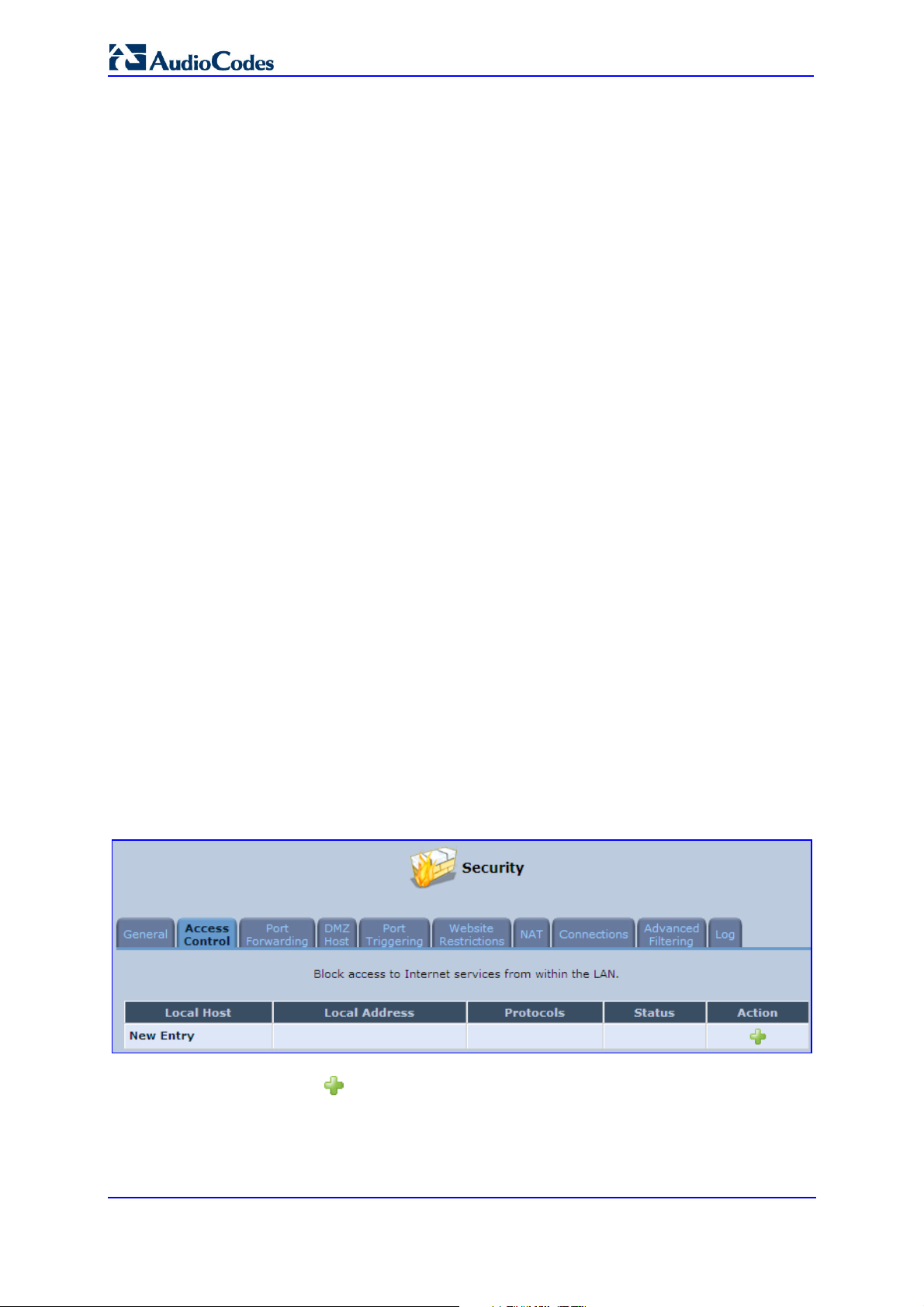
1. From the menu bar, click the Security menu, and in the screen 'Security', click the
Access Control tab; the screen 'Access Control' opens.
Figure 14-3: Access Control
2. Click the New icon; the screen 'Add Access Control Rule' opens (see the figure
below).
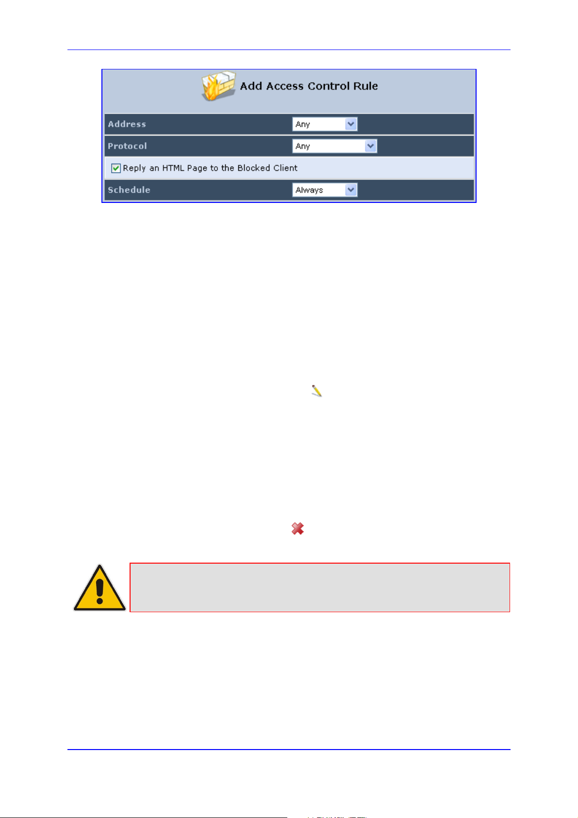
Figure 14-4: Add Access Control Rule
MP252 Multimedia Home Gateway 228 Document #: LTRT-23504
Page 29
MP252 Multimedia Home Gateway 14. Security
3. The parameter 'Address' enables you to specify the computer or group of computers for
which you would like to apply the access control rule. You can select between any or a
specific computer address in your LAN. If you choose the 'Specify Address' option, the
screen refreshes, and an 'Add' link appears. Click it to specify a computer address.
Specify an address by creating a 'Network Object'.
4. The parameter 'Protocol' lets you select or specify the type of protocol to be used. In
addition to the list of popular protocols it provides, you may also choose any or a specific
protocol. If you choose option 'Specify Protocol', the screen refreshes and an 'Add' link
appears. Click it to specify a protocol address.
5. The parameter 'Schedule' allows you to define the time period during which this rule
takes effect. You can select between 'Always' or a specific schedule. If you choose the
option 'Specify Schedule', the screen refreshes and an 'Add' link appears. Click it to
specify a schedule.
6. Click OK to save your settings; the 'Access Control' screen displays a summary of the
rule that you just added. Click the Edit icon to edit the access control rule for the
service; the screen 'Edit Service' opens.
7. Select the network group to which you would like to apply the rule and the schedule
during which the rule takes effect.
8. Click OK to save your changes and return to the 'Access Control' screen.
You can disable an access control rule and make the service available without having to
remove the service from 'Access Control'. This can be useful when making the service only
temporarily available and when expecting to reinstate the restriction in the future.
To temporarily disable rule, clear the check box adjacent to the service name.
To reinstate the restriction at a later time, recheck it.
To remove a rule, click the Remove icon for the service; the service is removed from
'Access Control'.
Note: When Web Filtering is enabled, HTTP services cannot be blocked by Access
Control.
14.3 Port Forwarding
By default, MP252 blocks all external users from connecting to or communicating with your
network. Therefore, the system is safe from hackers who may try to intrude on the network
and damage it. However, you may want to expose your network to the Internet in certain
limited and controlled ways to enable some applications to work from the LAN (game, voice
and chat applications, for example) and to enable Internet access to servers in the home
network. The Port Forwarding feature supports both of these functionalities.
Version 3.4.0 229 June 2011
Page 30
User's Manual
The 'Port Forwarding' screen lets you define the applications that require special handling by
MP252. You must select the application's protocol and the local IP address of the computer
using or providing the service. If required, you can add new protocols in addition to the most
common ones provided by MP252.
For example, to use an FTP application on one of your PCs, select 'FTP' from the list and
enter the local IP address or host name of the designated computer; all FTP-related data
arriving at MP252 from the Internet is then forwarded to the specified computer.
Similarly, to grant Internet users access to servers inside your home network, you must
identify each service that you want to provide and the PC that provides it. For example, to
host a Web server inside the home network you must select 'HTTP' from the list of protocols
and enter the local IP address or host name of the computer that hosts the Web server.
When an Internet user points her browser to the external IP address of MP252, it forwards
the incoming HTTP request to the computer that is hosting the Web server.
Additionally, port forwarding enables you to redirect traffic to a different port instead of the
one to which it was designated. If for example you have a Web server running on your PC on
port 8080 and you want to grant access to this server to anyone who accesses MP252 via
HTTP, do the following:
Define a port forwarding rule for the HTTP service, with the PC's IP or host name.
Specify 8080 in the field 'Forward to Port'.
All incoming HTTP traffic is now forwarded to the PC running the Web server on port 8080.
When setting a port forwarding service, you must ensure that the port is not already in use by
another application, which may stop functioning. A common example is when using SIP
signaling in Voice over IP - the port used by MP252's VoIP application (5060) is the same
port on which port forwarding is set for LAN SIP agents.
Note: Some applications, such as FTP, TFTP, PPTP and H323, require the support of
special specific Application Level Gateway (ALG) modules in order to work
inside the home network. Data packets associated with these applications
contain information that allows them to be routed correctly. An ALG is needed to
handle these packets and ensure that they reach their intended destinations.
MP252 is equipped with a robust list of ALG modules in order to enable
maximum functionality in the home network.
The ALG is automatically assigned based on the destination port.
MP252 Multimedia Home Gateway 230 Document #: LTRT-23504
Page 31

MP252 Multimedia Home Gateway 14. Security
To add a new port forwarding service :
1. From the menu bar, click the Security menu, and in the screen 'Security', click the Port
Forwarding tab; the screen 'Port Forwarding' opens.
Figure 14-5: Port Forwarding Screen
2. Click the New icon; the screen 'Add Port Forwarding Rule' opens.
Figure 14-6: Add Port Forwarding Rule
3. From the ‘Local Host’ drop-down list, select the network object (defined in Section 4.5.2
on page 50) or define one now by selecting the ‘User Defined’ option. This is the IP
address or host name of the computer that provides the service (the 'server'). Note:
Only one LAN computer can be assigned to provide a specific service or application.
4. From the ‘Protocol’ drop-down list, select the type of protocol (defined in Section 4.5.3
on page 51) or select ‘User Defined’ to define one now. You can select multiple
protocols for this rule.
Figure 14-7: Selecting Protocol Type
Version 3.4.0 231 June 2011
Page 32

User's Manual
5. Click the Advanced button to configure advanced settings:
a. Select the 'Specify Public IP Address' check box if you want to apply this rule on
MP252’s non-default IP address defined in the ‘NAT’ screen (see Section 14.7 on
page 240). Enter the additional external IP address in the 'Public IP Address' field.
Figure 14-8: Specifying Public IP Address
b. By default, MP252 forwards traffic to the same port as the incoming port. If you
wish to redirect traffic to a different port, then from the 'Forward to Port' drop-down
list, select the 'Specify', and then enter the port number in the field provided.
c. By default, the rule is always active. However, you can select a schedule rule that
defines the time during which the rule may be active. From the 'Schedule'
drop-down list, select a defined Schedule rule (defined in Section 4.5.1 on page 47)
or define a new one quickly by selecting 'User Defined'.
6. Click OK to save changes.
You can disable a port forwarding rule to make a service unavailable without having to
remove the rule from the screen 'Port Forwarding'. This can be useful when making the
service temporarily unavailable and when expecting to reinstate it in the future.
Figure 14-9: Select Check Box of Port Forwarding Rule (Active)
To temporarily disable a rule, clear the check box next to the service name.
To reinstate it at a later time, select the check box.
MP252 Multimedia Home Gateway 232 Document #: LTRT-23504
Page 33

MP252 Multimedia Home Gateway 14. Security
To remove a rule, click the Remove icon for the service; the service is permanently
removed.
Version 3.4.0 233 June 2011
Page 34

User's Manual
14.4 DMZ Host
The DMZ (Demilitarized) Host feature allows one local computer to be exposed to the
Internet. Designate a DMZ host to:
Use a special-purpose Internet service, such as an on-line game or video-conferencing
program, that is not present in the Local Servers list and for which no port range
information is available.
To expose one computer to all services, without restriction, irrespective of security.
Warning: A DMZ host is not protected by the firewall and may be vulnerable to attack.
Designating a DMZ host may also put other computers in the home network at risk. When
designating a DMZ host, you must consider the security implications and protect it if
necessary.
An incoming request for access to a service in the home network, such as a Web-server, is
fielded by MP252. MP252 forwards this request to the DMZ host (if one is designated) unless
the service is being provided by another PC in the home network (assigned in Local Servers),
in which case that PC receives the request instead.
To designate a local computer as a DMZ Host:
1. From the menu bar, click the Security menu, and in the screen 'Security', click the DMZ
Host tab; the screen 'DMZ Host' opens.
Figure 14-10: DMZ Host
2. Enter the local IP address of the computer to be designated as a DMZ host. Note that
only one LAN computer can be a DMZ host at any time.
3. Click OK to save your changes and return to the screen 'DMZ Host'.
You can disable the DMZ host so that it does not fully exposed to the Internet, but keep its IP
address recorded on the 'DMZ Host' screen. This may be useful if you wish to disable the
DMZ host but expect that you may want to enable it again in the future.
To disable the DMZ host so that it is not fully exposed to the Internet, clear the
check-box next to the DMZ IP designation and click OK.
To re-enable the DMZ host later, recheck the check-box.
MP252 Multimedia Home Gateway 234 Document #: LTRT-23504
Page 35

MP252 Multimedia Home Gateway 14. Security
14.5 Port Triggering
Port triggering can be used for dynamic port forwarding configuration. By setting port
triggering rules, you can allow inbound traffic to arrive at a specific LAN host, using ports
different than those used for the outbound traffic. This is called port triggering since the
outbound traffic triggers to which ports inbound traffic is directed.
For example, consider a gaming server that is accessed using UDP protocol on port 222.
The gaming server responds by connecting the user using UDP on port 333 when starting
gaming sessions. In such a case you must use port triggering, since this scenario conflicts
with the following default firewall settings:
The firewall blocks inbound traffic, by default.
The server replies to MP252's IP, and the connection is not sent back to your host, since
it is not part of a session.
To solve this, you need to define a Port Triggering entry, which allows inbound traffic on UDP
port 333, only after a LAN host generated traffic to UDP port 222. This results in accepting
the inbound traffic from the gaming server and sending it back to the LAN Host which
originated the outgoing traffic to UDP port 222.
To view port triggering settings:
1. From the menu bar, click the Security menu, and in the screen 'Security', click the Port
Triggering tab; the screen 'Port Triggering' opens. The screen lists all port triggering
entries.
Figure 14-11: Port Triggering
Version 3.4.0 235 June 2011
Page 36

User's Manual
To add an entry for the gaming example above:
1. From the drop-down list, select 'User Defined' to add an entry; the screen 'Edit Service'
opens.
Figure 14-12: Adding Port Triggering Rules
2. Enter a name for the service (e.g., 'game_server'), and then click the link New Trigger
Ports; the screen 'Edit Service Server Ports' opens.
Figure 14-13: Edit Service Server Ports
3. In the 'Protocol' drop-down list, select 'UDP'; the screen refreshes, providing source and
destination port options.
4. Leave the 'Source Ports' drop-down list at its default 'Any'. In the 'Destination Ports'
drop-down list, select 'Single'; the screen refreshes again, providing an additional field
in which you should enter '222' as the destination port.
Figure 14-14: Edit Service Server Ports
5. Click OK to save the settings.
6. In the screen 'Edit Service', click the link New Opened Ports; the screen 'Edit Service
Opened Ports' opens.
MP252 Multimedia Home Gateway 236 Document #: LTRT-23504
Page 37

MP252 Multimedia Home Gateway 14. Security
7. Similar to the trigger ports screen, select UDP as the protocol, leave the source port at
'Any', and enter a 333 as the single destination port.
Figure 14-15: Edit Service Opened Ports
8. Click OK to save the settings; the screen 'Edit Service' presents your entered
information. Click OK again to save the port triggering rule; the screen 'Port Triggering'
now includes the new port triggering entry.
Figure 14-16: New Port Triggering Rule
You can disable a port triggering rule without having to remove it from the screen 'Port
Triggering':
To temporarily disable a rule, clear the check box corresponding to the service name.
To reinstate it later, simply reselect the check box.
To remove a rule, click the Remove icon for the service; the service is permanently
removed.
There may be a few default port triggering rules listed when you first access the port
triggering screen. Note that disabling these rules may result in impaired MP252 functionality.
14.6 Website Restrictions
You can configure MP252 to block specific Internet websites so that they cannot be
accessed from computers in the home network. Moreover, restrictions can be applied to a
comprehensive and automatically-updated table of sites to which access is not
recommended.
To block access to a website:
Version 3.4.0 237 June 2011
Page 38

User's Manual
1. From the menu bar, click the Security menu, and in the screen 'Security', click the
Website Restrictions tab; the screen 'Website Restrictions' opens.
Figure 14-17: Website Restrictions
2. Click the New icon; the 'Restricted Website' screen appears.
Figure 14-18: Restricted Website
3. Enter the website address (IP address or URL) that you would like to make inaccessible
from your home network (all Web pages within the site are also blocked). If the website
address has multiple IP addresses, MP252 resolves all additional addresses and
automatically adds them to the restrictions table.
4. The 'Local Host' drop-down list provides you the ability to specify the computer or group
of computers for which you would like to apply the website restriction. You can select
between any or a specific computer address in your LAN. If you choose the option 'User
Defined', the screen refreshes and the 'Edit Network Object' appears:
Figure 14-19: Add a Specific Host
MP252 Multimedia Home Gateway 238 Document #: LTRT-23504
Page 39

MP252 Multimedia Home Gateway 14. Security
5. Click the New icon to specify a computer address. Specify an address creating a
'Network Object'.
6. The parameter Schedule allows you to define the time period during which this rule
takes effect. You can select between 'Always' or a specific schedule. If you choose the
option 'User Defined', the screen 'Edit Scheduler Rule' appears:
Figure 14-20: Add a Specific Schedule
7. Click the New icon to specify the time segment, and then click OK.
8. Click OK to save the settings; MP252 attempts to find the site. 'Resolving...' appears in
the Status column while the site is being located (the URL is 'resolved' into one or more
IP addresses).
9. Click the Refresh button to update the status if necessary. If the site is successfully
located, 'Resolved' appears in the status bar; if not, 'Hostname Resolution Failed'
appears.
If MP252 fails to locate the website:
1. Use a Web browser to verify that the website is available. If it is, then you probably
entered the website address incorrectly.
2. If the website is unavailable, return to the screen 'Website Restrictions' later and click
the button Resolve Now to verify that the website can be found and blocked by MP252.
3. You can edit the website restriction by modifying its entry under the column 'Local Host'
in the screen 'Website Restrictions'.
To modify an entry:
1. Click the icon Edit for the restriction; the screen 'Restricted Website' opens. Modify the
website address, group or schedule as required.
2. Click OK to save your changes and return to the screen 'Website Restrictions'.
To ensure that all current IP addresses corresponding to the restricted
websites are blocked:
1. Click the button Resolve Now; MP252 checks each of the restricted website addresses
and ensures that all IP addresses at which this website can be found are included in the
IP addresses column.
You can disable a restriction to make a website available again without having to remove it
from the screen 'Website Restrictions'. This can be useful when making the website
temporarily available and when expecting to block it again in the future.
To temporarily disable a rule, clear the check box adjacent to the service name.
To reinstate it at a later time, recheck the check box.
Version 3.4.0 239 June 2011
Page 40

To remove a rule, click the Remove icon for the service; the service is permanently
removed.
14.7 NAT
MP252 features a configurable Network Address Translation (NAT) and Network Address
Port Translation (NAPT) mechanism, allowing you to control the network addresses and
ports of packets routed through your gateway. When enabling multiple computers on your
network to access the Internet using a fixed number of public IP addresses, you can statically
define which LAN IP address will be translated to which NAT IP address and/or ports.
By default, MP252 operates in NAPT routing mode. However, you can control your network
translation by defining static NAT/NAPT rules. Such rules map LAN computers to NAT IP
addresses. The NAT/NAPT mechanism is useful for managing Internet usage in your LAN,
or complying with various application demands. For example, you can assign your primary
LAN computer with a single NAT IP address, in order to assure its permanent connection to
the Internet. Another example is when an application server with which you wish to connect,
such as a security server, requires that packets have a specific IP address – you can define
a NAT rule for that address.
User's Manual
MP252 Multimedia Home Gateway 240 Document #: LTRT-23504
Page 41

MP252 Multimedia Home Gateway 14. Security
To define NAT:
1. From the menu bar, click the Security menu, and in the screen 'Security', click the NAT
tab; the screen 'NAT' opens.
Figure 14-21: NAT Screen
2. Before configuring NAT/NAPT rules, you must first enter the additional public IP
addresses obtained from your ISP as your NAT IP addresses, in the 'NAT IP Addresses
Pool' section. The primary IP address used by the WAN device for dynamic NAPT
should not be added to this table.
a. To add a NAT IP address, click the New icon; the 'Edit Item' screen appears.
Figure 14-22: Adding a NAT IP Address
b. From the 'Network Object Type' drop-down list, select between IP address, subnet
or range, and then enter the information respectively, and click OK to save the
settings.
Version 3.4.0 241 June 2011
Page 42

User's Manual
3. To add a new NAT/NAPT rule:
a. In the 'NAT/NAPT Rule Sets' section, click the New Entry link; the 'Add NAT/NAPT
Rule' screen appears.
Figure 14-23: Adding NAT/NAPT Rule
This screen is divided into two main sections: 'Matching' and 'Operation'. The 'Matching'
section defines the LAN addresses to be translated to the external addresses, which are
defined in the 'Operation' section.
4. 'Matching' section (define characteristics of the packets matching the rule):
a. Source Address: source address of packets sent or received by MP252. You can
select the computer or group of computers on which you would like to apply the rule.
To apply the rule on all the LAN hosts, select 'Any' . If you would like to add a new
address, select the 'User Defined'. This commences a sequence to add a new
Network Object, representing the new host.
b. Destination Address: destination address of packets sent or received by MP252.
This address can be configured in the same manner as the source address. This
entry enables further filtration of the packets.
c. Protocol: specifies a traffic protocol. Selecting the 'Show All Services' option
expands the list of available protocols. Select a protocol or add a new one using the
'User Defined' option. This commences a sequence that adds a new Service,
representing the protocol. Using a protocol requires observing the relationship
between a client and a server to distinguish between the source and destination
ports.
MP252 Multimedia Home Gateway 242 Document #: LTRT-23504
Page 43

MP252 Multimedia Home Gateway 14. Security
5. Operation section (define the operation to apply on the IP addresses, matching the
criteria defined above): NAT or NAPT.
• NAT Addresses: NAT address into which the original IP address is translated. The
drop-down list displays all of your available NAT addresses/ranges from which you
can select an entry. If you would like to add a single address or a sub-range from
the given pool/range, select the 'User Defined' option. This commences a
sequence that adds a new Network Object, representing the new host.
• NAPT Address: NAPT address into which the original IP address is translated.
The drop-down list displays all of your available NAPT addresses/ranges from
which you can select an entry. If you would like to add a single address or a
sub-range from the given pool/range, select the 'User Defined' option. This
commences a sequence that adds a new Network Object, representing the new
host. . Note, that in this case the network object may only be an IP address, as
NAPT is port-specific.
♦
NAPT Ports: specify the port(s) of the IP address into which the original IP
address is translated. Enter a single port or select 'Range' (the screen
refreshes, enabling you to enter a range of ports).
6. Select the 'Log Packets Matched by This Rule' check box to log the first packet from a
connection that was matched by this rule.
7. By default, the 'Schedule' rule is always active. However, you can configure scheduler
rules to define time segments during which the rule may be active.
8. Click OK to save the settings.
Version 3.4.0 243 June 2011
Page 44

User's Manual
14.8 Connections
The connection list displays all the connections that are currently open, as well as various
details and statistics. You can use this list to close an undesired connection by clicking its
corresponding action icon. The basic display includes the name of the protocol, the different
ports it uses, and the direction in which the connection was initiated.
To view currently open connections:
1. From the menu bar, click the Security menu, and in the screen 'Security', click the
Connections tab; the screen 'Connections' opens.
2. From the Connections Per Page drop-down list, select the number of connections that
you want displayed per page. To browse to the next page, click the icon or the page
number located at the bottom left of the page.
Figure 14-24: Connections Screen
To display additional details in the Connection list, click the Advanced button.
The 'Approximate Max. Connections' value displays the amount of additional concurrent
MP252 Multimedia Home Gateway 244 Document #: LTRT-23504
connections possible.
Page 45

MP252 Multimedia Home Gateway 14. Security
14.9 Advanced Filtering
Advanced filtering is designed to allow comprehensive control over the firewall's behavior.
You can define specific input and output rules, control the order of logically similar sets of
rules and make a distinction between rules that apply to WAN and LAN devices.
To view MP252's advanced filtering options:
From the menu bar, click the Security menu, and in the screen 'Security', click the
Advanced Filtering tab; the 'Advanced Filtering' opens.
Figure 14-25: Advanced Filtering
Version 3.4.0 245 June 2011
Page 46

User's Manual
This screen is divided into two identical sections, one for 'Input Rule Sets' and the other for
'Output Rule Sets', which are for configuring inbound and outbound traffic, respectively. Each
section is comprised of subsets, which can be grouped into three main subjects:
1. Initial rules - rules defined here are applied first, on all MP252 devices.
2. Network devices rules - rules can be defined per MP252.
3. Final rules - rules defined here are applied last, on all MP252 devices.
Numerous rules are automatically inserted by the firewall to provide improved security and
block harmful attacks.
Note: The order of appearance of the firewall rules determines the sequence by which
they are applied.
To configure an advanced filtering rule:
1. After choosing the traffic direction and the device on which to set the rule, click the
corresponding link New Entry; the screen 'Add Advanced Filter' opens.
Figure 14-26: Add Advanced Filter
MP252 Multimedia Home Gateway 246 Document #: LTRT-23504
Page 47

MP252 Multimedia Home Gateway 14. Security
2. In the section 'Matching', define a match between IP addresses and a traffic protocol:
a. Configure the source address of the packets sent to or received from the network
object. To add an address, select the option 'User Defined' from the drop-down list;
the screen 'Edit Network Object' appears.
Figure 14-27: Add a Specific Host
Click the New icon; this commences a sequence that adds a new network
object.
b. Configure the destination address of the packets sent to or received from the
network object. This address can be configured in the same manner as the source
address.
c. From the 'Protocol' drop-down list, select a specific traffic protocol or add a new
one (by selecting 'User Defined'); the 'Edit Services' screen appears. Click the link
New Server Ports; this commences a sequence that adds a new protocol.
3. Select the check box 'DSCP' to mark a DSCP value on packets matching this rule; the
screen refreshes, allowing you to enter the hexadecimal value of the DSCP.
4. Select the check box 'Priority' to add a priority to the rule; the screen refreshes, allowing
you to select between one of eight priority levels, zero being the lowest and seven the
highest (each priority level is mapped to low/medium/high priority). This sets the priority
of a packet on the connection matching the rule, while routing the packet.
Figure 14-28: Set Priority Rule
5. Select the check box 'Length' to specify the length of packets or the length of their data
portion.
6. In the section 'Operation', define the action of the rule:
• Drop: Deny access to packets that match the source and destination IP addresses
and service ports defined in 'Matching'.
• Reject: Deny access to packets that match the source and destination IP
addresses and service ports defined in 'Matching' and sends and sends an ICMP
error or a TCP reset to the origination peer.
• Accept Connection: Allow access to packets that match the source and
destination IP addresses and service ports defined in 'Matching'. The data transfer
session is handled using Stateful Packet Inspection (SPI).
Version 3.4.0 247 June 2011
Page 48

User's Manual
• Accept Packet: Allow access to packets that match the source and destination IP
addresses and service ports defined in 'Matching'. The data transfer session is not
handled using Stateful Packet Inspection (SPI), meaning that other packets that
match this rule are not automatically allowed access. For example, this can useful
when creating rules that allow broadcasting.
7. Under the section 'Logging', select the parameter 'Log Packets Matched By This Rule'
to log the first packet from a connection that was matched by this rule.
8. By default, the 'Schedule' rule is always active. However, you can configure scheduler
rules to define time segments during which the rule may be active.
9. Click OK to save the settings.
14.10 Security Log
The Security log displays a list of firewall-related events, including attempts to establish
inbound and outbound connections, attempts to authenticate at an administrative interface
(Web-based management or Telnet terminal), firewall configuration and system start-up.
To view the Security Log:
1. From the menu bar, click the Security menu, and in the screen 'Security', click the Log
tab; the screen 'Log' opens.
Figure 14-29: Security Log
2. The log table displays the following:
• Time: to determine the time the event occurred.
• Event: type of event. There are five types of events:
MP252 Multimedia Home Gateway 248 Document #: LTRT-23504
Page 49

MP252 Multimedia Home Gateway 14. Security
♦
Inbound Traffic: The event is a result of an incoming packet.
♦
Outbound Traffic: The event is a result of outgoing packet.
♦
Firewall Setup: Configuration message.
♦
WBM Login: Indicates that a user has logged in to WBM.
♦
CLI Login: Indicates that a user has logged in to CLI (via Telnet).
• Event-Type: textual description of the event:
♦
Blocked: The packet was blocked. The message is color-coded red.
♦
Accepted: The packet was accepted. The message is color-coded green.
• Details: details of the packet or the event, such as protocol, IP addresses, ports,
etc.
To change the security log settings:
1. In the 'Log' screen, click Settings; the screen 'Log Settings' opens.
Figure 14-30: Security Log Settings
2. Select the types of activities for which you would like to have a log message generated.
• Accepted Events:
♦
Accepted Incoming Connections: Write a log message for each successful
attempt to establish an inbound connection to the home network.
♦
Accepted Outgoing Connections: Write a log message for each successful
attempt to establish an outgoing connection to the public network.
• Blocked Events:
Version 3.4.0 249 June 2011
Page 50

User's Manual
♦
All Blocked Connection Attempts: Write a log message for each blocked
attempt to establish an inbound connection to the home network or vice versa.
You can enable logging of blocked packets of specific types by disabling this
option, and enabling some of the more specific options below it.
♦
Specific Events: Specify the blocked events that should be monitored. Use
this to monitor specific event such as SynFlood. A log message is generated if
either the corresponding check-box is checked, or the check-box 'All Blocked
Connection Attempts' is checked.
• Other Events:
♦
Remote Administration Attempts: Write a log message for each
remote-administration connection attempt, whether successful or not.
♦
Connection States: Provide extra information about every change in a
connection opened by the firewall. Use this option to track connection
handling by the firewall and Application Level Gateways (ALGs).
• Log Buffer:
♦
Prevent Log Overrun: Select this check box in order to stop logging firewall
activities when the memory allocated for the log fills up.
3. Click OK to save the settings.
MP252 Multimedia Home Gateway 250 Document #: LTRT-23504
Page 51

MP252 Multimedia Home Gateway 15. Advanced Networking Features
15 Advanced Networking Features
This chapter describes various advanced networking features such as DHCP.
15.1 IP Address Distribution
The MP252's Dynamic Host Configuration Protocol (DHCP) server makes it possible to
easily add computers that are configured as DHCP clients to the home network. It provides a
mechanism for allocating IP addresses and delivering network configuration parameters to
such hosts. MP252's default DHCP server is the LAN bridge.
A client (host) sends out a broadcast message on the LAN requesting an IP address for itself.
The DHCP server then checks its list of available addresses and leases a local IP address to
the host for a specific period of time and simultaneously designates this IP address as `taken'.
At this point, the host is configured with an IP address for the duration of the lease.
The host can choose to renew an expiring lease or let it expire. If it chooses to renew a lease
then it also receives current information about network services, as it did with the original
lease, allowing it to update its network configurations to reject any changes that may have
occurred since it first connected to the network. If the host wishes to terminate a lease before
its expiration it can send a release message to the DHCP server, which then makes the IP
address available for use by others.
The MP252 embedded DHCP server provides the following features:
Displays a list of all DHCP host devices connected to MP252
Defines the range of IP addresses that can be allocated to the LAN
Defines the length of time for which dynamic IP addresses are allocated
Provides the above configurations for each LAN device and can be configured and
enabled / disabled separately for each LAN device
Can assign a static lease to a LAN PC so that it receives the same IP address each time
it connects to the network even if this IP address is within the range of addresses that
the DHCP server may assign to other computers
Provides the DNS server with the host name and IP address of each PC that is
connected to the LAN
In addition, MP252 can act as a DHCP relay, escalating DHCP responsibilities to a WAN
DHCP server. In this case, MP252 acts merely as a router, while its LAN hosts receives their
IP addresses from an external DHCP server on the WAN.
With MP252's optional Zero Configuration Technology feature, the IP Auto Detection method
detects statically-defined IP addresses in addition to MP252's DHCP clients. It learns all the
IP addresses on the LAN and integrates the collected information with the database of the
DHCP server. This allows the DHCP server to issue valid leases, thus avoiding conflicting IP
addresses used by other computers in the network.
Version 3.4.0 251 July 2011
Page 52

User's Manual
To view services currently provided by the DHCP server:
In the 'Advanced' screen, click the IP Address Distribution icon; the 'IP Address
Distribution' screen appears.
Figure 15-1: DHCP Server Summary
Note: If the 'Service' column displays “Disabled”, then DHCP services are not being
provided to hosts connected to the network through that MP252 interface. This
means that MP252 does not assign IP addresses to these computers, which is
useful if you wish to work with static IP addresses only.
MP252 Multimedia Home Gateway 252 Document #: LTRT-23504
Page 53

MP252 Multimedia Home Gateway 15. Advanced Networking Features
15.1.1 DHCP Server Parameters
The procedure below describes how to edit a service provided by the DHCP server.
To edit the DHCP server settings for a device:
1. In the 'IP Address Distribution' screen, click the Edit icon corresponding to the entry
that you want to edit; the DHCP Server settings for this device are displayed.
Figure 15-2: DHCP Settings Screen
2. From the 'IP Address Distribution' drop-down list, select whether to disable the MP252
DHCP server, or enable DHCP (MP252 serves as a DHCP server or DHCP relay).
3. In the ‘Start IP Address’ and ‘End IP Address’ fields, define the IP address range. This
determines the number of hosts that may be connected to the network in this subnet.
The 'Start IP Address' field specifies the first IP address that may be assigned in this
subnet; the 'End IP Address' field specifies the last IP address in the range.
4. In the ‘Subnet Mask’ field, define the subnet to which an IP address belongs (e.g.,
255.255.0.0).
5. In the ‘Lease Time in Minutes’ field, define the time for which each device is assigned an
IP address by the DHCP server when it connects to the network. When the lease
expires, the server determines if the computer has disconnected from the network. If it
has, then the server may reassign this IP address to a newly-connected computer. This
feature ensures that IP addresses that are not in use become available for other
computers on the network.
6. Select the ‘Provide Host Name If Not Specified by Client’ check box to enable the
MP252 to assign clients a default name if they do not have a host name.
7. Click OK.
Version 3.4.0 253 June 2011
Page 54

User's Manual
15.1.2 DHCP Relay Parameters
The MP252 can act as a DHCP relay if you want to dynamically assign IP addresses from a
DHCP server other than the MP252's DHCP server. .
Note: When implementing DHCP relay, you must configure the WAN of the MP252 to
operate in routing mode.
To configure a device as a DHCP relay:
1. In the 'IP Address Distribution' screen, click the Edit icon corresponding to the entry
that you want to edit; the DHCP Server settings for this device are displayed.
2. From the 'IP Address Distribution' drop-down list, select the 'DHCP Relay' option; the
'DHCP Settings' screen appears.
Figure 15-3: DHCP Settings
3. Click the New icon; the 'DHCP Relay Server Address' screen appears.
Figure 15-4: DHCP Relay Server Address Screen
4. In the 'IP Address' field, enter the IP address of the DHCP server.
5. Click OK to save your changes.
6. Click OK once more in the 'DHCP Settings' screen.
7. Change MP252's WAN to operate in routing mode:
a. On the menu bar, click the Network Connections menu; the 'Network
Connections' screen appears.
b. Click the Edit icon corresponding to the WAN Ethernet connection; the 'WAN
Ethernet Properties' screen appears.
c. Click the Routing tab.
d. From the 'Routing Mode' drop-down list, select 'Route'.
e. Click OK to save the settings.
MP252 Multimedia Home Gateway 254 Document #: LTRT-23504
Page 55

MP252 Multimedia Home Gateway 15. Advanced Networking Features
15.1.3 Viewing DHCP Clients
The procedure below describes how to view a list of hosts (computers) that are allocated IP
addresses by the DHCP server.
To view a list of computers currently recognized by the DHCP server:
1. In the 'IP Address Distribution' screen, click the Connection List button; the 'DHCP
Connections' screen appears.
Figure 15-5: DHCP Connection Screen
15.1.4 Defining Static DHCP Clients
The procedure below describes how to define a static (fixed) IP address for a DHCP client.
To define a DHCP client with a fixed IP address:
1. In the 'IP Address Distribution' screen, click the Connection List button; the 'DHCP
Connections' screen appears.
2. Click the New icon; the 'DHCP Connection Settings' screen appears.
Figure 15-6: DHCP Connection Settings Screen
3. In the 'Host Name' field, enter a host name for this connection.
4. In the 'IP Address' field, enter the fixed IP address to be assigned to the computer.
5. In the 'MAC Address' field, enter the MAC address of the computer's network card.
Note: A device's fixed IP address is actually assigned to the specific network card's
(NIC) MAC address installed on the LAN computer. If you replace this network
card then you must update the device's entry in the DHCP Connections list with
the new network card's MAC address.
Version 3.4.0 255 June 2011
Page 56

User's Manual
6. Click OK to save the settings; the 'DHCP Connections' screen reappears displaying the
defined static connection. This connection can be edited or deleted.
MP252 Multimedia Home Gateway 256 Document #: LTRT-23504
Page 57

MP252 Multimedia Home Gateway 15. Advanced Networking Features
15.2 DNS Server
The DNS Server icon allows you to manage the MP252 Domain Name System (DNS)
server. The DNS server does not require configuration. However, you can view the list of
computers known by the DNS, edit the host names or IP addresses of computers in the list,
or manually add a new computer to the list.
DNS provides a service that translates domain names into IP addresses and vice versa.
MP252's DNS server is an auto-learning DNS, which means that when a new computer is
connected to the network, the DNS server learns its name and automatically adds it to the
DNS table. Other network users may immediately communicate with this computer using
either its name or its IP address.
The MP252 DNS server also provides the following functionalities:
Shares a common database of domain names and IP addresses with the DHCP server.
Supports multiple subnets within the LAN simultaneously.
Automatically appends a domain name to unqualified names.
Allows new domain names to be added to the database using MP252's Web interface.
Permits a computer to have multiple host names.
Permits a host name to have multiple IPs (needed if a host has multiple network cards).
Version 3.4.0 257 June 2011
Page 58

User's Manual
To add a new host computer to the DNS table:
1. In the 'Advanced' screen, click the icon; the DNS table is displayed.
Figure 15-7: DNS Server
2. Click the New icon; the 'DNS Entry' screen appears.
Figure 15-8: DNS Entry
3. Enter the computer's host name and IP address.
4. Click OK to save your changes.
To edit the host name or IP address of an entry:
1. Click the Edit icon corresponding to the host that you want to edit; the 'DNS Entry'
screen appears.
2. If the host was manually added to the DNS Table, you can modify its host name and/or
IP address. If it wasn't, you can only modify its host name.
3. Click OK to save your changes.
To remove a host from the DNS table:
Click the Remove icon corresponding to the host that you want to delete; the entry is
removed from the table.
15.3 Dynamic DNS
The Dynamic DNS (DDNS) feature allows you to alias a dynamic IP address to a static
hostname, allowing your computer to be more easily accessible from various locations on the
Internet. Typically, when you connect to the Internet, your ITSP assigns an unused IP
address from a pool of IP addresses, and this address is used only for the duration of a
specific connection. Dynamically assigning addresses extends the usable pool of available
IP addresses, whilst maintaining a constant domain name.
When using the DDNS service, each time the IP address provided by your ITSP changes,
the DNS database changes accordingly to reflect the change. In this way, even though your
IP address changes often, your domain name remains constant and accessible.
MP252 Multimedia Home Gateway 258 Document #: LTRT-23504
Page 59

MP252 Multimedia Home Gateway 15. Advanced Networking Features
To be able to use the Dynamic DNS (DDNS) feature, you must first open a free DDNS
account at http://www.dyndns.org/account/create.html. When applying for an account, you
need to specify a user name and password. Have them readily available when customizing
MP252's DDNS support. For detailed information on DDNS, see http://www.dyndns.org.
To open a dynamic DNS account:
1. In the 'Advanced' screen, click the Personal Domain Name (Dynamic DNS) icon;
the 'Personal Domain Name (Dynamic DNS)' screen appears.
Figure 15-9: Personal Domain Name (Dynamic DNS) Screen
2. Click the New icon to add a new connection; the 'Personal Domain Name (Dynamic
DNS)' screen appears.
Figure 15-10: Personal Domain Name (Dynamic DNS) - Adding
3. In the ‘Host Name’ field, enter your full DDNS domain name.
4. From the ‘Connection’ drop-down list, select the connection to which you want to couple
the DDNS service. The DDNS service uses only the selected device, unless failover is
enabled. In this case, the failed-to device is used instead (assuming its route rules
consent), until the chosen device is up again. In a single WAN scenario, this field
appears as static text (non-configurable). This is applicable if you have multiple WAN
devices.
Version 3.4.0 259 June 2011
Page 60

User's Manual
5. From the ‘Provider’ drop-down list, select your DDNS service provider and then click the
link Click here to initiate and manage your subscription to open the selected
provider's account creation Web page. For example, if you select ‘dyndns.org’, the
following page opens: http://www.dyndns.com/account.
6. In the ‘User Name’ and ‘Password’ fields, enter your DDNS user name and password,
respectively.
7. To enable use of special links (such as such as www.<your host>.dyndns.org), select
the ‘Wildcard’ check box.
8. In the ‘Mail Exchanger’ field, enter your mail exchange server address to redirect all
e-mails arriving at your DDNS address to your mail server.
9. To designate the mail exchange server as a backup server, select the ‘Backup MX’
check box.
10. To temporarily take your site offline (i.e., prevent traffic from reaching your DDNS
domain name), select the ‘Offline’ check box. This redirects DNS requests to an
alternative, predefined URL. The availability of this feature depends on your DDNS
account's level of service. The redirection URL must be configured through the account
as well.
11. From the ‘SSL Mode’ drop-down list, select the certificate validation method used by
MP252 to validate the DDNS server's certificate upon secured connection to DDNS
using HTTPS:
• None: The server's certificate is not validated.
• Chain: Validates the entire certificate chain. When selecting this option, the screen
refreshes, displaying the 'Validate Time' drop-down list for selecting whether or not
to validate the certificate's expiration time ('Ignore' or 'Check' respectively). If the
certificate has expired, the connection terminates immediately.
• Direct: Ensures that the server's certificate is directly signed by the root certificate.
This option also provides the 'Validate Time' drop-down list for validation of the
certificate's expiration time, as described above.
12. Click OK.
MP252 Multimedia Home Gateway 260 Document #: LTRT-23504
Page 61

MP252 Multimedia Home Gateway 15. Advanced Networking Features
15.4 Routing
This section describes how to configure routing rules and enable routing protocols. These
are configured in the ‘Routing’ screen, as described below.
To access the Routing screen:
In the 'Advanced' screen, click the Routing icon; the 'Routing' screen appears.
Figure 15-11: Routing Rules
15.4.1 Managing Routing Table Rules
The procedure below describes how to add routing rules.
To add routing tables:
1. In the 'Advanced' screen, click the New icon in the Routing Table; the 'Route
Settings' screen appears.
Figure 15-12: Route Settings Screen
2. From the ‘Name’ drop-down list, select the network device for which you want to add a
routing rule.
Version 3.4.0 261 June 2011
Page 62

User's Manual
3. In the ‘Destination’ field, enter the destination host, subnet address, network address, or
default route. The destination for a default route is “0.0.0.0”.
4. In the ‘Netmask’ field, enter the network mask that used in conjunction with the
destination to determine when a route is used.
5. In the ‘Gateway’ field, enter the MP252's IP address.
6. In the ‘Metric’ field, enter the measurement of the preference of a route. Typically, the
lowest metric is the most preferred route. If multiple routes exist to a given destination
network, the route with the lowest metric is used.
7. Click OK to save your settings.
15.4.2 Routing Protocols
MP252 supports IGMP multicasting, which allows hosts connected to a network to be
updated whenever an important change occurs in the network. A multicast is simply a
message that is sent simultaneously to a pre-defined group of recipients. When you join a
multicast group you receive all messages addressed to the group, similar to an e-mail
message sent to a mailing list.
IGMP multicasting enables UPnP capabilities over wireless networks and may also be useful
when connected to the Internet through a router. When an application running on a computer
in the home network sends out a request to join a multicast group, MP252 intercepts and
processes the request. If MP252 is set to 'Minimum Security', no further action is required.
However, if MP252 is set to 'Typical Security' or 'Maximum Security', you must add the
group's IP address to MP252's 'Multicast Groups' screen. This allows incoming messages
addressed to the group to pass through the MP252 firewall and on to the correct LAN
computer.
To configure routing protocols:
1. In the 'Advanced' screen, under the Internet Group Management Protocol (IGMP)
group, do the following:
a. Select the 'Enabled' check box to enable IGMP multicasting.
b. Select the ‘IGMP Fast Leave' check box if you want MP252 to stop forwarding
traffic to a host that is the only subscriber, immediately upon request (without query
delay).
c. Select the 'IGMP Multicast to Unicast' check box to enable MP252 to convert the
incoming multicast data stream into unicast format to route it to the specific LAN
host that requested the data. In this way, MP252 prevents flooding the rest of the
LAN hosts with irrelevant multicast traffic.
2. Under the Packet Streaming Engine group, from the ‘Software Acceleration’
drop-down list, select the packet flow speed:
• None: Packet Streaming Engine (PSE) is disabled
• Medium: PSE is active (recommended)
• High: PSE traffic is prioritized over other traffic
3. Click OK.
15.5 PPPoE Relay
PPPoE relay enables MP252 to relay packets on PPPoE connections while keeping its
designated functionality for any additional connections.
To enable PPPoE relay:
MP252 Multimedia Home Gateway 262 Document #: LTRT-23504
Page 63

MP252 Multimedia Home Gateway 15. Advanced Networking Features
1. In the 'Advanced' screen, click the PPPoE Relay icon; the 'PPPoE Relay' screen
appears.
Figure 15-13: PPPoE Relay Screen
2. Select the 'Enabled' check box.
3. Click OK.
Version 3.4.0 263 June 2011
Page 64

User's Manual
MP252 Multimedia Home Gateway 264 Document #: LTRT-23504
Page 65

MP252 Multimedia Home Gateway 16. Home Media
16 Home Media
16.1 Universal Plug and Play
Universal Plug-and-Play (UPnP) is a networking architecture that provides compatibility
among networking equipment, software, and peripherals. UPnP-enabled products can
seamlessly connect and communicate with other UPnP-enabled devices without the need for
user configuration, centralized servers, or product-specific device drivers. This technology
leverages existing standards and technologies, including TCP/IP, HTTP 1.1 and XML,
facilitating the incorporation of UPnP capabilities into a wide range of networked products for
the home.
UPnP technologies are rapidly adopted and integrated into widely-used consumer products
such as Windows XP. Therefore it is critical that today's Residential Gateways be
UPnP-compliant. Your MP252 is at the forefront of this development, offering a complete
software platform for UPnP devices. This means that any UPnP-enabled control point (client)
can dynamically join the network, obtain an IP address and exchange information about its
capabilities and those of other computers on the network. They can subsequently
communicate with each other directly, thereby further enabling peer-to-peer networking. And
this all happens automatically, providing a truly zero-configuration network.
16.1.1 Enabling UPnP on MP252
The procedure below describes how to enable the UPnP feature on MP252.
To enable UPnP:
1. In the 'Advanced' screen, click the Universal Plug and Play icon; the 'Universal
Plug and Play' screen appears.
Figure 16-1: Advanced - Universal Plug n Play
2. Select the ‘Allow Other Network Users to Control MP252’s Network Features’ to enable
the UPnP feature. This allows you to define UPnP services on any of the LAN hosts.
3. Select the ‘Enable Automatic Cleanup of Old Unused UPnP Services’ to enable
automatic cleanup of invalid rules. This feature checks the validity of all UPnP services
every five minutes, and removes old and obsolete services, unless a user-defined rule
depends on them.
4. From the ‘WAN Connection Publication’ drop-down list, select which WAN information
is published by MP252. By default, MP252 publishes only its main WAN connection,
which is controllable by UPnP entities. However, you may select the 'Publish All WAN
Connections' option if you wish to grant UPnP control over all of MP252’s WAN
connections.
Version 3.4.0 265 July 2011
Page 66

User's Manual
16.1.2 Adding UPnP-enabled PC to Home Network
If your computer is running an operating system that supports UPnP such as Windows XP,
you can add the computer to your home network and access the Web-based Management
directly from Windows.
To add a UPnP-enabled computer to the home network:
Connect the PC to MP252; the PC automatically recognizes and adds to the home
network. MP252 is added to 'My Network Places' as the Internet Gateway Device and
allows configuration via a standard Windows interface. A message appears on the
notification area of the taskbar notifying that the PC has been added to the network.
To access the Web-based management directly from Windows:
1. Open the 'My Network Places' window by double-clicking its desktop icon.
Figure 16-2: My Network Places
2. Double-click the MP252 Internet Gateway Device icon. The MP252 Web interface
‘Login’ screen appears in a browser window. This method is similar to opening a
browser window and typing in '192.168.1.1'.
16.1.3 Monitoring Connection between MP252 and Internet
The procedure below describes how to monitor the status of the connection between MP252
and the Internet.
To monitor the status of the connection between MP252 and the Internet:
1. Open the 'Network Connections' control panel.
2. Double-click the Internet Connection icon. The 'Internet Connection Status' window
appears:
MP252 Multimedia Home Gateway 266 Document #: LTRT-23504
Page 67

MP252 Multimedia Home Gateway 16. Home Media
Figure 16-3: Internet Connection Status
16.1.4 Making Local Services available to PCs on Internet
You can make services provided by computers in the home network available to computers
on the Internet. For example, you may designate a PC in your home network to act as a Web
server, allowing computers on the Internet to request pages from it. Or a game that you want
to play over the Internet may require that specific ports be opened to allow communication
between your PC and other players.
To make local services available to computers on the Internet:
1. Open the 'Network Connections' control panel.
2. Right-click 'Internet Connection', and then choose Properties; The 'Internet Connection
Properties' window appears.
Version 3.4.0 267 June 2011
Page 68

User's Manual
Figure 16-4: Internet Connection Properties
3. Click the Settings button; the 'Advanced Settings' window.
Figure 16-5: Advanced Settings
4. Select a local service that you would like to make available to computers on the Internet;
the 'Service Settings' window automatically appears.
MP252 Multimedia Home Gateway 268 Document #: LTRT-23504
Page 69

MP252 Multimedia Home Gateway 16. Home Media
Figure 16-6: Service Settings
5. Enter the local IP address of the computer that provides this service and then click OK.
6. Select other services as desired and repeat the previous step for each.
7. Click OK to save the settings.
To add a local service that is not listed in the 'Advanced Settings'
window:
1. Follow steps 1-3 above.
2. Click the Add button; the 'Service Settings' window appears.
Figure 16-7: Service Settings – Add Service
3. Complete the fields as indicated in the window.
4. Click OK to close the window and return to the 'Advanced Settings' window; the service
is selected.
5. Click OK to save the settings.
Version 3.4.0 269 June 2011
Page 70

User's Manual
17 Add-On Servers and Disk Management
17.1 External File Server
MP252 provides a file server utility, allowing you to perform various tasks on your files, such
as manage file server shares and define access control lists. The file server utility
complements MP252’s disk management.
To configure the file server:
1. In the 'Advanced' screen, click the File Server icon; the screen File Server'
opens.
Figure 17-1: File Server Screen
2. Configure the following:
• Enabled: Select or clear this check box to enable or disable this feature.
• NetBIOS Workgroup: MP252 workgroup name that is displayed in the Windows
network map of LAN hosts.
• Automatic Sharing:
♦
Automatically Share All Partitions: A partitioned storage device connected
to MP252 is automatically displayed and shared by all LAN computers. This
feature is enabled by default.
MP252 Multimedia Home Gateway 270 Document #: LTRT-23504
Page 71

MP252 Multimedia Home Gateway 17. Add-On Servers and Disk Management
♦
Allow Guest Access: From the drop-down list, select a permission level,
according to which the LAN users access the share:
Read/Write: Every LAN user can read and write the shared files without
authentication.
Read Only: Every LAN user can only read the shared files.
Disabled: LAN users must authenticate themselves to access the share.
They can use the share according to their permissions defined in the
'User Settings' screen.
• File Server Shares: Define file shares on your disk partitions, as described in the
following sections.
17.1.1 Automatic File Sharing
By default, all partitions are automatically shared and displayed.
To share specific directories or partitions:
1. Clear the 'Automatically Share All Partitions' check box, and then click Apply. The list of
all automatically shared partitions disappears.
2. In the ‘File Server Shares’ table, click New icon to define a new share; the 'File
Server Share Settings' screen appears.
Figure 17-2: File Server Share Settings Screen
3. Enter the share's name (default is “share”), path, and (optionally) comment. The share's
name is not case sensitive. Even if entered in upper-case letters, the name is displayed
in lower case after saving the setting.
4. Associate a user or group of users with the share to grant them access to the shared
files, by clicking the New User or New Group link in the Users or Groups table. Note
that the user’s settings must have the ‘Microsoft File and Printer Sharing Access’ check
box selected under the 'Permissions' section (see ‘Configuring Users’ on page 44); the
‘User’ screen appears:
Version 3.4.0 271 June 2011
Page 72

User's Manual
Figure 17-3: User Screen
d. From the ‘Name’ drop-down list, select the user name and the allowed access.
e. Click OK.
5. Click OK to save the settings. The 'File Server' screen appears, displaying the share.
Figure 17-4: File Server Screen with the Share
Click the share's name to view its content. The screen refreshes as the share is accessed
This screen enables you to modify and view the content of your file share. In the upper
section of this screen, you can modify your file share by adding files or directories to it. Use
the drop-down list to select an action:
Upload a File: Uploads a file to the share. The screen refreshes - enter the location of
the file to upload, or click the Browse button to browse for the file. Click the Upload
button to upload the file.
Upload a Directory: You can also upload an entire directory of files, by performing the
following:
a. Create a tarball archive out of the target directory.
b. Enter the location of the archive, or click the Browse button to browse to its
location.
c. Click the Upload button to upload the archive.
Create a new Directory: You can create a new directory by simply typing its name and
clicking Go.
Paste from Clipboard: This option appears only after using the 'Copy to Clipboard'
option to copy a directory or file from one directory to another.
The lower section of the screen displays your share's content. You can click the different
directory names to access them or you can download, rename, copy or remove the
directories using the standard action icons.
17.2 Disk Management
The Disk Management icon allows you to configure disk management. MP252 can
operate as a disk manager for either internal disks connected through IDE, or external
storage devices connected through USB or FireWire. Your home-network's LAN devices can
share this storage device as a mapped network drive and exchange information without
directly accessing each other. The Web interface provides disk management utilities such as
partitioning and formatting.
MP252 Multimedia Home Gateway 272 Document #: LTRT-23504
Page 73

MP252 Multimedia Home Gateway 17. Add-On Servers and Disk Management
An internal disk or a connected storage device appears in the Network Map (see Section 5
on page 55). You can view information about the disk by clicking its icon.
The device supports storage devices with FAT32, NTFS, and Linux EXT2/3 file systems.
These file systems have different sharing and security settings. If the connected storage
device or at least one of its partitions has the NTFS file system, a message appears in the
'Disk Management’ screen appears.
Note: MP252 based on the Conexant Solos, Mindspeed Malindi2 or Freescale
platform allows both read and write access to an NTFS partition.
To configure disk management:
1. In the 'Advanced' screen, click the icon; the ‘Disk Management' screen appears.
Figure 17-5: Disk Management Screen
Note: To define a system storage area, the disk or at least one of its partitions should
be formatted. This storage area holds the data used by the MP252’s services.
For security, it is recommended to format the disk or its partition in the EXT2 or
EXT3 file system, although FAT32 is supported as well.
2. To enable disk management, select the ‘Enabled’ check box.
Version 3.4.0 273 June 2011
Page 74

User's Manual
3. To set the first identified formatted partition as the location of the system storage area,
select the ‘Automatically Create System Storage Area’ check box. This setting is valid
until the storage device is disconnected. When reconnected, MP252 may select another
partition for this purpose. To define the system storage area manually, clear this check
box. The screen refreshes, displaying the 'System Storage Area' field in which you must
enter the partition's letter. In this scenario, the setting remains permanent even after the
storage device is disconnected and reconnected afterwards.
Figure 17-6: Manually Defining System Storage Area
4. In the Disks table, you can view a list of your connected storage devices. The 'Device'
column displays the names MP252 grants connected devices. Click this link to view the
device's 'Disk Information' screen. If a disk is partitioned, the 'Partitions' column displays
its partition names. If the partitions are formatted, their name includes a letter.
5. In the RAID Devices table, you can view the RAID devices (if configured).
17.2.1 Disk Partitions
This section describes how to configure partition and format storage devices.
17.2.1.1 Connecting a Mass Storage Device
To set up a file server that is shared by all LAN computers, you need to connect a mass
storage device (e.g. disk-on-key or hard drive) to the USB port on your MP252. A mass
storage device must first be partitioned and formatted. If your device is already partitioned, it
is recommended that you delete its partitions before proceeding, as a partition can only be
added on unallocated disk space.
MP252 Multimedia Home Gateway 274 Document #: LTRT-23504
Page 75

MP252 Multimedia Home Gateway 17. Add-On Servers and Disk Management
To add a Windows formatted partition:
1. In the Disks table in the 'Disk Management' screen, click the disk device link. The 'Disk
Information' screen appears.
Figure 17-7: Disk Information
2. In the 'Partitions' table, click the Add New Partition icon; the 'Partition Type' screen
appears.
Figure 17-8: Partition Type
Version 3.4.0 275 June 2011
Page 76

User's Manual
3. Select 'Primary Partition', and then click Next; the 'Partition Size' screen appears.
Figure 17-9: Partition Size
4. Enter a volume for the new partition (in mega bytes), and then click Next; the 'Partition
Format' screen appears.
Figure 17-10: Partition Format
5. Select 'Format the Partition', and then click Next; the 'Partition File System' screen
appears.
Figure 17-11: Partition File System
MP252 Multimedia Home Gateway 276 Document #: LTRT-23504
Page 77

MP252 Multimedia Home Gateway 17. Add-On Servers and Disk Management
6. Select 'Windows (FAT32) (LBA)' as the file system for the partition and then click Next;
the 'Partition Summary' screen appears.
Figure 17-12: Partition Summary
7. Click Finish to create the new partition; the 'Disk Information' screen reappears,
refreshing as the partition formatting progresses, until the status changes to 'Ready'.
Figure 17-13: Formatting Complete – Partition Ready
The new partition names are designated as "A", "B" etc, and appear under the 'Name'
column of the 'Partitions' section.
Version 3.4.0 277 June 2011
Page 78

User's Manual
17.2.1.2 Formatting a Partition
A partition can be formatted in EXT2, EXT3, FAT32 and NTFS file systems.
To partition a disk:
1. In the Disks table in the 'Disk Management' screen, click the disk device link; the 'Disk
Information' screen appears.
2. In the 'Partitions' table, click the Edit Partition icon of the partition you would like to edit;
the 'Partition Properties' screen appears.
Figure 17-14: Partition Properties
3. Click Format Partition; the 'Partition Format' screen appears.
Figure 17-15: Partition Format
4. Select a file system for the partition and then click Next. A warning screen appears,
alerting you that all the data on the partition will be lost.
5. Click OK to format the partition; the screen refreshes as the partition formatting
progresses. When the format is complete, the status will change to 'Ready'.
MP252 Multimedia Home Gateway 278 Document #: LTRT-23504
Page 79

MP252 Multimedia Home Gateway 17. Add-On Servers and Disk Management
17.2.1.3 Checking a Partition
The procedure below describes how to check a partition.
To check a partition:
1. In the Disks table in the 'Disk Management' screen, click the disk device link; the 'Disk
Information' screen appears.
2. In the 'Partitions' section, click the Edit Partition icon of the partition you would like to
check; the 'Partition Properties' screen appears.
Figure 17-16: Partition Format
3. Click Check Partition; a warning screen appears, alerting you that the partition will be
set to offline.
4. Click OK; the screen refreshes as the partition checking progresses. When the check is
complete, the status changes to 'Ready'.
17.2.1.4 Deleting a Partition
The procedure below describes how to delete a partition.
To delete a partition:
1. In the Disks table in the 'Disk Management' screen, click the disk device link; the 'Disk
Information' screen appears.
2. In the 'Partitions' section, click the Remove Partition icon of the partition you would like
to delete; a warning screen appears, alerting you that all the data on the partition will be
lost.
3. Click OK to delete the partition.
Version 3.4.0 279 June 2011
Page 80

User's Manual
17.2.2 System Storage Area
MP252 uses a specific location on a storage device for storing data used by its various
services. The following are the services that use the system storage area:
Printer spool and drivers
Mail server spool
Backup of MP252’s configuration file (rg_conf)
PBX-related audio files for voice mail, auto attendants and music on-hold
FTP server
Mail boxes information
Users' home directories
Web server content
Prior to enabling these services, you should create either EXT2/3 (recommended) or FAT32
partitions, as described in the previous sections, and define at least one of them as the
system storage area.
Note: Data cannot be written to partitions formatted with NTFS, unless MP252 is
based on the Conexant Solos, Mindspeed Malindi2 or Freescale platform.
Consequently, if you define an NTFS partition as the system storage area, the
services mentioned earlier will not operate on MP252.
MP252 Multimedia Home Gateway 280 Document #: LTRT-23504
Page 81

MP252 Multimedia Home Gateway 17. Add-On Servers and Disk Management
To define a system storage area:
1. Under the System Storage Area group in the 'Disk Management' screen, clear the
‘Automatically Create System Storage Area’ check box; the screen refreshes displaying
the 'System Storage Area' field, in which you must enter the partition's letter.
Figure 17-17: Disk Management Screen – Check Box Cleared
2. Click OK to save the settings.
If you wish to view the system directories, verify that the system storage area is shared. Then,
browse to \\mp252 (use a Windows Explorer window if you are using a browser other than
Internet Explorer).
Version 3.4.0 281 June 2011
Page 82

User's Manual
17.2.3 RAID Management
MP252 supports Redundant Array of Independent Disks (RAID) on storage devices
connected to it by USB or by FireWire. A RAID device is a logical device that has physical
devices underlying it. These physical devices are disk partitions. The supported RAID levels
are:
Level 0 – Provides data striping, or spreading out blocks of each file across multiple
disk drives, but no redundancy. This improves performance but does not deliver fault
tolerance. If one drive fails then all data in the array is lost.
Level 1 – Provides disk mirroring. This is a technique in which data is written to two
duplicate disks simultaneously, providing data redundancy. This method improves
performance and delivers fault tolerance.
Level 5 – With a minimum of three disks, this level provides data striping and utilizes
one disk for backup information, which enables it to restore any other disk in the array.
Before creating the RAID device, you must create disk partitions (as described previously) on
the different disk drives. Each RAID device can have multiple underlying devices (partitions).
When using RAID1, it is recommended that these partitions be of the same size to avoid
disk-space loss due to mirroring. A disk partition configured with RAID can no longer be
managed as a regular partition, but only be controlled by the RAID device. From the moment
RAID is configured, it is the RAID device that can be shared, scanned, formatted and
mounted as a regular partition.
17.2.3.1 Creating a RAID Device
The procedure below describes how to create a RAID device.
To create a RAID device:
1. In the RAID Devices table in the ‘Disk Management’ screen, click the Add RAID
Device link; the 'RAID Properties' screen appears:
Figure 17-18: RAID Properties Screen
2. From the ‘RAID Level’ drop-down list, select the RAID level (RAID0, RAID1 or RAID5).
3. In the 'Mount Point' field, enter a name for the mount point of the RAID device.
4. Choose the underlying devices (your pre-configured partitions) in the next drop-down
lists. For RAID1 you may choose only one device and later add another one.
MP252 Multimedia Home Gateway 282 Document #: LTRT-23504
Page 83

MP252 Multimedia Home Gateway 17. Add-On Servers and Disk Management
5. Click Next; the 'Partition Format' screen appears.
Figure 17-19: Partition Format Screen
6. Select 'Format the partition' and then click Next.
Figure 17-20: Partition File System Screen
7. Select the format type, and then click Next; the 'Partition Summary' screen displays a
summary of the chosen device properties.
Figure 17-21: Partition Summary Screen
8. Click the Finish button to execute the RAID device creation.
As soon as a RAID device is created, its formatting begins. If the device is RAID1 and has
two underlying devices, its re-synchronization process (partition mirroring) begins
simultaneously. During re-synchronization the RAID device is fully usable and can be
mounted and used.
Version 3.4.0 283 June 2011
Page 84

User's Manual
The figure below depicts a successful configuration of two RAID devices as they appear in
the Raid Devices table in the 'File Server' screen. The first is RAID0, consisting of two
underlying partitions (one on each disk), and the second is RAID1, consisting of another set
of underlying partitions. Note that the RAID0 total space is the sum of the two partitions, while
the RAID1 total space is the size of one partition (due to mirroring).
Figure 17-22: Added RAID Devices
17.2.3.2 Using a RAID Device
When RAID is configured over the existing partitions, these partitions are no longer
independent. It is therefore necessary that you update the location of the system storage
area:
1. In the 'Disk Management' screen, verify that the 'Automatically Create System Storage
Area' check box is selected. If you wish to define the system storage area manually,
clear the check box and enter the name of the designated mount point.
2. Click OK to save the settings.
17.2.3.3 Maintaining a RAID Device
A RAID device differs from a regular partition by not being part of a physical disk. It therefore
resides and is maintained on MP252. RAID maintenance is divided into two aspects:
Maintaining the RAID device itself:
• In the RAID Device table in the 'Disk Management' screen, click the Edit icon of
the RAID device; the 'RAID Properties' screen appears in which you can:
♦
Enable or disable the RAID device using the 'Enabled' check box.
♦
Change the mount point assigned to the device.
♦
Add or remove the underlying devices (can be done for RAID1 and RAID5
only).
Maintaining the partition:
• In the 'RAID Properties' screen, click the device name; the 'Partition Properties'
screen appears in which you can check and format the RAID partition.
17.2.3.4 Replacing RAID Underlying Devices
Adding or removing a RAID underlying device can only be performed on RAID1 and RAID5
configurations. RAID1 can operate with just one device (although mirroring is unavailable),
and RAID5 can operate with one device less than its original amount of devices.
The names of the RAID underlying devices appear on the 'RAID Properties' screen. Each
device is followed by a status:
Active: The device is controlled by RAID.
Inactive: The device failed to join the RAID array or does not exist.
Faulty: The device joined the RAID array but was marked as faulty due to an error. It is
inactive and should be replaced.
Replacing a device on RAID1 or RAID5 is done by first removing the faulty device and then
adding a new one. The new device's size must be at least the size of the existing one.
MP252 Multimedia Home Gateway 284 Document #: LTRT-23504
Page 85

MP252 Multimedia Home Gateway 17. Add-On Servers and Disk Management
To remove a faulty device from RAID1:
1. In the 'RAID Properties' screen, click the faulty device's Delete icon.
2. Click OK.
To add a new device instead of the one removed:
1. In the RAID Device table in the 'Disk Management' screen, click the Edit icon of the
RAID device; the 'RAID Properties' screen appears with a drop-down list allowing you to
choose the new partition to be added.
2. Choose the partition, and then click OK.
After adding a new device, RAID1 starts a recovery process in which the content of the
existing partition is mirrored to the new device. If the addition or recovery fails, the device
status is set to inactive (this status appears in the 'RAID Properties' screen. In such cases,
the device should be removed and another may be added. You can manipulate your disk
partitions. However, it is recommended to configure your disks before setting up RAID. Once
RAID is configured, you will not be able to delete an underlying partition, or create a new
partition on a disk that one of its partitions is underlying RAID, unless you disable or delete
the RAID device. Changing a disk's partition table when its partitions are under RAID (even if
RAID is disabled) may result in the need to reconstruct the RAID.
Version 3.4.0 285 June 2011
Page 86

User's Manual
17.3 Print Server
MP252 includes a print server that allows printers attached to MP252 through the USB
connection(s) to be shared by all computers on the LAN. Such a printer appears in the
Network Map. You can access the printer settings directly, by clicking the printer icon in the
Network Map or as described below.
To configure a print server:
1. In the 'Advanced' screen, click the Print Server icon; the ‘Print Server’ screen
appears.
Figure 17-23: Advanced – Print Server Screen
2. Select or clear (as required) the following check boxes:
• Enabled: Enables or disables the print server feature.
• Spool to Disk: Allows print jobs to be written to a disk before printing.
• Allow Guest Access: Allows network users that have not logged in with a
username and password to use the shared printer. If you want to restrict access to
the network printer, you can clear this check box and grant user-specific
permissions by creating a user set to ‘Internet Printer Access’ (see Section 4.4).
• LPD Support: Enables the LPD protocol.
• IPP Support: Enables the IPP protocol.
• Microsoft Shared Printing Support: Enables the Samba protocol.
3. The Printers table lists the MP252 printers, their status as well as their print job
information. To view the printer’s properties and optionally, to define a new name for the
printer, click the Edit icon corresponding to the printer; the 'Printer' screen appears.
Figure 17-24: Advanced – Printer Screen
MP252 Multimedia Home Gateway 286 Document #: LTRT-23504
Page 87

MP252 Multimedia Home Gateway 17. Add-On Servers and Disk Management
4. To change the displayed name of the printer, in the ‘Name’ field, enter a new name.
5. To set the printer as the default printer, select the ‘Create Default Device Mode’ check
box.
17.3.1 Connecting and Setting up a Printer on Windows
The procedure below describes how to set up a network printer that is connected to the
MP252 USB port and shared by all LAN computers, running on the Windows operating
system.
Note: The above configuration must be applied to each LAN PC individually in order
to use the network printer.
To set up a printer running on Windows:
1. Log in to MP252; the disk and printer shares available on MP252 is displayed:
Figure 17-25: MP252 Shares
2. Click the printer icon that you want to designate as a LAN printer; a warning appears.
Version 3.4.0 287 June 2011
Page 88

User's Manual
Print queue monitor and
Print queue monitor and
3. Click Yes; you are prompted to select a printer driver from a list. If unavailable, you can
either browse to a location on your computer where you have stored the driver, or click
Have Disk and insert the CD containing the driver (supplied with your printer). After a
short upload and installation of the driver, the printer's print queue window appears,
determining that the printer is ready for use. The new printer is added to your "Printers
and Faxes" list as a network printer (to view this list press, in Windows Control Panel,
select "Printers and Faxes"). As any printer, you can choose to make it your default
printer, or specify its use when printing.
4. Print a test page by right-clicking the printer icon in the disk and printer shares window
and selecting Properties; the 'Print Test Page' button is located at the bottom of the
General tab.
17.3.2 Print Protocols
The Samba protocol with which you have created a network printer in the previous section,
allows you to upload Windows print drivers to MP252, enabling all Windows-based LAN
hosts to connect to the network printer.
MP252 provides two additional protocols for computers to connect to its printers:
Internet Printing Protocol (IPP) - the recommended protocol, offering fast installation
and ease of use.
Line Printer Daemon (LPD) - legacy network printing protocol, which should only be
used for printing from computers that do not support IPP.
The following table compares the specifications of the three protocols:
Table 17-1: IPP, Samba, and LPD Specifications
Specification IPP Samba
Installation
Driver upload
Supported clients
Job feedback and
control
Printer control
Access controls
Note: For Mac Users: When connecting a print server to a MAC computer, you must
Windows, Unix, Mac
management console
Print queue monitor
Print and administrator Print permission only
verify that the printer connected to MP252 is supported by Mac OS as a
network printer. Supported printers are marked with an "X" at the following
URL: http://docs.info.apple.com/article.html?artnum=301175#hpdrivers.
Easy Easy Difficult
None Supported None
management console
17.3.2.1 Internet Printing Protocol
This section describes how to connect computers to MP252 printers, using the IPP protocol.
LPD
Windows, Mac Windows, Unix, Mac
Management console
only
None None
None
17.3.2.1.1 Setting Up an IPP Printer on Windows
MP252 Multimedia Home Gateway 288 Document #: LTRT-23504
The procedure below describes how to set up an IPP printer on Windows.
Page 89

MP252 Multimedia Home Gateway 17. Add-On Servers and Disk Management
To set up an IPP printer on Windows:
1. In the 'Network Map' screen, click the printer icon to view the 'Printer' screen.
Figure 17-26: Printer Screen – IPP URL
2. Copy the IPP URL to the clipboard.
3. On your Windows computer connected to MP252, from the Start menu, point to
Settings, then Printers and Faxes, and then click Add Printer; the Add Printer Wizard
starts.
4. Click Next to proceed with the wizard sequence.
5. Select 'A network printer…' and then click Next.
Figure 17-27: Local or Network Printer
6. Select 'Connect to a printer on the Internet…', and then paste the printer's IPP URL in
the 'URL' field, and then click Next.
Figure 17-28: Specify a Printer
Version 3.4.0 289 June 2011
Page 90

User's Manual
7. You may be asked to select the driver's make and model or its location. If so, provide the
location on MP252 to where you have uploaded the driver (e.g. “\\MP252\A”), and click
Next.
8. Click Finish to exit the wizard.
MP252 Multimedia Home Gateway 290 Document #: LTRT-23504
Page 91

MP252 Multimedia Home Gateway 17. Add-On Servers and Disk Management
17.3.2.1.2 Setting Up an IPP Printer on Linux
The procedure below describes how to set up an IPP printer on Linux operating systems.
You should use CUPS Daemon (CUPSD) when operating with Linux.
To set up an IPP printer on Linux:
1. In the 'Network Map' screen, click the printer icon to view the 'Printer' screen.
Figure 17-29: Printer Screen – IPP URL
2. Copy the IPP URL to the clipboard.
3. On your Linux computer connected to MP252, browse to http://localhost:631, and then
choose Manage Printers.
Figure 17-30: Linux CUPS Management
4. Click Add Printer.
Version 3.4.0 291 June 2011
Page 92

User's Manual
Figure 17-31: Add Printer
5. In the 'Name' field, type the printer's name and then click Continue.
Figure 17-32: Printer Name
6. From the 'Device' drop-down list, select 'Internet Printing Protocol (http)' and then click
Continue.
MP252 Multimedia Home Gateway 292 Document #: LTRT-23504
Page 93

MP252 Multimedia Home Gateway 17. Add-On Servers and Disk Management
Figure 17-33: Printing Protocol
7. Paste the printer's IPP URL in the 'Device URI' field, and then click Continue.
Figure 17-34: IPP URL
8. The next window displays a manufacturer drop-down list. Select your printer's
manufacturer and click Continue.
9. The next window displays a printer model drop-down list. Select your printer's model
and click Continue.
10. The last window displays the following confirmation message: 'Printer has been added
successfully'.
11. To test your printer's connection from a Linux PC, open a shell and enter the following
command:
$ echo hello | lpr -P<Printer Name>
17.3.2.1.3 Setting Up an IPP Printer on Mac
The procedure below describes how to set up an IPP printer on Mac operating systems.
Version 3.4.0 293 June 2011
Page 94

User's Manual
To set up an IPP printer on Mac:
1. On your Mac computer connected to MP252, open the 'Print & Fax' utility from 'System
Preferences'; the 'Print & Fax' screen appears.
Figure 17-35: Print & Fax
2. Click the + (add) button; the 'Printer Browser' screen appears.
3. Select the IP Printer tab.
MP252 Multimedia Home Gateway 294 Document #: LTRT-23504
Page 95

MP252 Multimedia Home Gateway 17. Add-On Servers and Disk Management
Figure 17-36: Printer Browser – IP Printer
4. In this screen, configure the following:
a. From the 'Protocol' drop-down list, select IPP.
b. In the 'Address' field, enter MP252’s IP address (192.168.1.1).
c. In the 'Queue' field, enter the section of the path containing the folder and printer
names, as it appears in the 'Printer' screen. For example, “/printers/MFC9750”.
d. The 'Name' and 'Location' fields are optional; the default name is the gateway's IP
address.
e. From the 'Print Using' drop-down list, select your printer's make and model.
Version 3.4.0 295 June 2011
Page 96

User's Manual
5. Click the Add button; the new printer appears in the 'Print & Fax' screen.
Figure 17-37: Print & Fax – New IPP Printer
MP252 Multimedia Home Gateway 296 Document #: LTRT-23504
Page 97

MP252 Multimedia Home Gateway 17. Add-On Servers and Disk Management
17.3.2.2 Microsoft Shared Printing (Samba)
The procedure below describes how to set up Microsoft Shared Printing (Samba).
To set up Microsoft shared printing (Samba):
1. On your Mac computer connected to MP252, open the 'Print & Fax' utility from 'System
Preferences'; the 'Print & Fax' screen appears.
Figure 17-38: Print & Fax
Version 3.4.0 297 June 2011
Page 98

User's Manual
2. Click the + (add) button; the 'Printer Browser' screen appears.
Figure 17-39: Printer Browser – Default Browser
3. Click the More Printers button; The following screen appears.
Figure 17-40: Printer Browser – More Printers
MP252 Multimedia Home Gateway 298 Document #: LTRT-23504
Page 99

MP252 Multimedia Home Gateway 17. Add-On Servers and Disk Management
4. From the second drop-down list, select 'Network Neighborhood'.
5. Select the 'Home' workgroup and then click Choose.
Figure 17-41: Printer Browser – MP252
6. Select MP252, and then click Choose.
7. Select the printer, and from the 'Printer Model' drop-down list, select your printer's make
and model.
Figure 17-42: Printer Browser – Printer Model
8. Click Add; the new printer appears in the 'Print & Fax' screen.
Figure 17-43: Print & Fax – New Samba Printer
Version 3.4.0 299 June 2011
Page 100

User's Manual
17.3.2.3 Line Printer Daemon (LPD)
This section describes how to connect computers to MP252 printers, using the LPD protocol.
17.3.2.3.1 Setting Up an LPD Printer on Windows
Before configuring the LPD protocol on a LAN PC, ensure that a print driver for the specific
printer is installed.
Note: The following configuration must be applied to each LAN PC individually in
order to use the network printer.
To set up an LPD printer on Windows:
1. On your Windows computer connected to MP252, from the Start menu, point to
Settings, then Printers and Faxes, and then click Add Printer; the Add Printer Wizard
starts.
2. Click Next to proceed with the wizard sequence.
3. Select 'Local printer attached to this computer' and then click Next.
4. Clear the 'Automatically detect and install my Plug and Play printer', and then click Next.
MP252 Multimedia Home Gateway 300 Document #: LTRT-23504
 Loading...