

Page 1

Important Product Information for
Document #: LTRT
-
23003
MP-252 Series
TThhaannkk--yyoouu ffoorr CChhoooossiinngg AAuuddiiooCCooddeess
This important product information includes Regulatory and Safety information.
Before you start using this product, please read the Safety Instructions provided. These Instructions can also be downloaded from the AudioCodes Website at
http://www.audiocodes.com/library. This document, the Installation Manual and User’s Manual (as well as software files and other documentation) can be
downloaded from the AudioCodes Website at http://www.audiocodes.com/downloads. Check that all items as listed in the Installation Manual are supplied in the
shipped package. If any items are missing or if you have any queries, contact your AudioCodes sales representative. If your product was purchased directly from
AudioCodes, then contact support@audiocodes.com. If the product was purchased from AudioCodes’ Distributors, Partners, or Resellers, then use the contact details
provided by these sellers.
The device will be inoperable when the mains power fails and the battery backup is not connected.
This equipment meets the applicable Industry Canada Terminal Equipment technical specifications. This is confirmed by the registration numbers. The abbreviation,
IC, before the registration number signifies that registration was performed based on a declaration of conformity indicating that Industry Canada technical
specifications were met. It does not imply that Industry Canada approved the equipment.
This Class [B] digital apparatus complies with Canadian ICES-003.
Cet appareil numérique de la classe [B] est conforme à la norme NMB-003 du Canada.
Operation is subject to the following two conditions: (1) this device may not cause interference, and (2) this device must accept any interference, including
interference that may cause undesired operation of the device.
This device and its antenna(s) must not be co-located or operating in conjunction with any other antenna or transmitter.
The County Code Selection feature is disabled for products marketed in the US/Canada.
This equipment complies with IC RSS-102 radiation exposure limits set forth for an uncontrolled environment. This equipment should be installed and operated with
minimum distance of 20 cm between the radiator and your body.
1. To avoid risk of fire, use 26 AWG or higher wiring to connect the FXO, ADSL telecom ports.
2. Disconnect TNV circuit connector before removing cover.
3. Unit must be powered only by power limited Class 2 certified power adapter
Ports Safety Status
Ethernet (100Base-TX) SELV
FXS TNV-2
FXO, ADSL TNV-3
WWaarrnniinngg
IInndduussttrryy CCaannaaddaa NNoottiiccee
FFoorr CCuussttoommeerrss iinn CCaannaaddaa
IICC RRaaddiiaattiioonn EExxppoossuurree SSttaatteemmeenntt
SSaaffeettyy NNoottiiccee
Page 2

AudioCodes Inc.
International Headquarters
Contact
FFCCCC PPaarrtt 1155
This equipment has been tested and found to comply with the requirements for a Class B digital device under Part 15 of the Federal Communications Commission
(FCC) rules. These requirements are intended to provide reasonable protection against harmful interference in a residential installation. This equipment generates
uses and can radiate radio frequency energy and, if not installed and used in accordance with the instructions, may cause harmful interference to radio
communications. However, there is no guarantee that interference will not occur in a particular installation.
If this equipment does cause harmful interference to radio or television reception, which can be determined by turning the equipment off and on, the user is
encouraged to try to correct the interference by one or more of the following measures:
• Reorient or relocate the receiving antenna.
• Increase the separation between the equipment and receiver.
• Connect the equipment into an outlet on a circuit different from that to which the receiver is connected.
• Consult the dealer or an experienced radio/TV technician for help.
Changes or modifications to this equipment not expressly approved by the party responsible for compliance could void the user’s authority to operate the
equipment. This device complies with Part 15 of the FCC rules. Operation is subject to the following two conditions: (1) this device may not cause harmful
interference, and (2) this device must accept any interference received, including interference that may cause undesired operation.
Privacy of communications may not be ensured when using this telephone. To ensure safety of users, the FCC has established criteria for the amount of radio
frequency energy that can be safely absorbed by a user or bystander according to the intended usage of the product. This product has been tested and found to
comply with the FCC criteria. The handset may be safely held against the ear of the user. The telephone base shall be installed and used such that parts of the user’s
body other than the hands are maintained at a distance of approximately 20cm (8 inches) or more. This Class B digital apparatus complies with Canadian ICES-003.
FFCCCC PPaarrtt 6688 aanndd AACCTTAA
This equipment complies with Part 68 of the FCC rules and with technical requirements adopted by the Administrative Council for Terminal Attachments (ACTA). The
label on the back or bottom of this equipment contains, among other things, a product identifier in the format US:EW7DL01B80-759700. This identifier must be
provided to your telephone service provider upon request.
The plug and jack used to connect this equipment to premises wiring and the telephone network must comply with the applicable Part 68 rules and technical
requirements adopted by ACTA. A compliant telephone cord and modular plug is provided with this product. It is designed to be connected to a compatible modular
jack that is also compliant. An RJ11 jack should normally be used for connecting to a single line and an RJ14 jack for two lines. See Installation Instructions in the
user’s manual.
The Ringer Equivalence Number (REN) is used to determine how many devices you may connect to your telephone line and still have them ring when you are called.
The REN for this product is encoded as the 6th and 7th characters following the US: in the product identifier (e.g., if ## is 03, the REN is 0.3). In most, but not all areas,
the sum of all RENs should be five (5.0) or less. For more information, please contact your telephone service provider.
This equipment may not be used with Party Lines. If you have specially wired alarm dialing equipment connected to your telephone line, ensure the connection of
this equipment does not disable your alarm equipment. If you have questions about what will disable the alarm equipment, consult your telephone service provider
or a qualified installer.
If this equipment is malfunctioning, it must be unplugged from the modular jack until the problem has been corrected. Repairs to this telephone equipment can only
be made by the manufacturer or its authorized agents. For repair procedures, follow the instructions outlined under the Limited Warranty.
If this equipment is causing harm to the telephone network, the telephone service provider may temporarily discontinue your telephone service. The telephone
service provider is required to notify you before interrupting service. If advance notice is not practical, you will be notified as soon as possible. You will be given the
opportunity to correct the problem and the telephone service provider is required to inform you of your right to file a complaint with the FCC. Your telephone service
provider may make changes in its facilities, equipment, operation, or procedures that could affect the proper functioning of this product. The telephone service
provider is required to notify you if such changes are planned.
If this product is equipped with a corded or cordless handset, it is hearing aid compatible.
If this product has memory dialing locations, you may choose to store emergency telephone numbers (e.g., police, fire, medical) in these locations. If you do store or
test emergency numbers, please:
• Remain on the line and briefly explain the reason for the call before hanging up.
• Perform such activities in off-peak hours, such as early morning or late evening.
If trouble is experienced with this equipment, for repair or warranty information, please contact AudioCodes Inc. or call +1-732-469-0880. If the equipment is causing
harm to the telephone network, the telephone company may request that you disconnect the equipment until the problem is resolved.
IInndduussttrryy CCaannaaddaa
Operation is subject to the following two conditions: (1) this device may not cause harmful interference, and (2) this device must accept any interference, including
interference that may cause undesired operation.
The term ‘’IC:‘’ before the certification/registration number only signifies that the Industry Canada technical specifications were met.
The Ringer Equivalence Number (REN) for this terminal equipment is 0.1B. The REN is an indication of the maximum number of devices allowed to be connected to a
telephone interface. The termination on an interface may consist of any combination of devices subject only to the requirement that the sum of the RENs of all the
devices does not exceed five. This product meets the applicable Industry Canada technical specifications.
NNeettwwoorrkk CCoommppaattiibbiilliittyy ooff FFXXOO PPoorrttss
The products support the Telecom networks in EU that comply with ES 203 021.
27 World's Fair Drive, Somerset, NJ 08873
Tel: +1-732-469-0880 Fax: +1-732-496-2298
1 Hayarden Street, Airport City, Lod 70151
P.O. Box 255, Ben Gurion Airport, Israel, 70100
Tel: +972-3-976-4000 Fax: +972-3-976-4040
www.audiocodes.com/info
Website: www.audiocodes.com
Page 3

Document #: LTRT
-
23003
EEuurrooppee--EEUU DDeeccllaarraattiioonn ooff CCoonnffoorrmmiittyy
Application of Council
Directives
2004/108/EC
2006/95/EC
1999/5/EC Annex-II of the
Directive
ErP Directive 2009/125/EC)
I, the undersigned, hereby declare that the equipment specified above conforms to the above Directives and Standards.
Signature Date (Day/Month/Year) Location
I. Zusmanovich, Compliance Engineering Manager
Czech
Danish
Dutch
English
Estonian
Finnish
French
German
Greek
Hungarian
Icelandic æki þetta er í samræmi við tilskipun Evrópusambandsins 89/336/EEC, 73/23/EEC, 2009/125/EC, 1999/5/EC
Italian
Latvian
Lithuanian
Maltese
Norwegian Dette produktet er i samhørighet med det Europeiske Direktiv 89/336/EEC, 73/23/EEC, 2009/125/EC, 1999/5/EC
Polish
Portuguese AudioCodes Ltd declara que este MP-252 está conforme com os requisitos essenciais e outras disposições da Directiva 89/336/EEC, 73/23/EEC, 2009/125/EC, 1999/5/EC
Slovak AudioCodes Ltd týmto vyhlasuje, že MP-252 spĺňa základné požiadavky a všetky príslušné ustanovenia Smernice 89/336/EEC, 73/23/EEC, 2009/125/EC, 1999/5/EC
Slovene Šiuo AudioCodes Ltd deklaruoja, kad šis MP-252 atitinka esminius reikalavimus ir kitas 89/336/EEC, 73/23/EEC, 2009/125/EC, 1999/5/EC Direktyvos nuostatas.
Spanish
Swedish
AudioCodes Ltd tímto prohlašuje, že tento MP-252 je ve shodě se základními požadavky a dalšími příslušnými ustanoveními směrnice 89/336/EEC, 73/23/EEC,
2009/125/EC, 1999/5/EC
Undertegnede AudioCodes Ltd erklærer herved, at følgende udstyr MP-252 overholder de væsentlige krav og øvrige relevante krav i direktiv 89/336/EEC, 73/23/EEC,
1999/5/EC
Hierbij verklaart AudioCodes Ltd dat het toestel MP-252 in overeenstemming is met de essentiële eisen en de andere relevante bepalingen van richtlijn 89/336/EEC,
73/23/EEC, 2009/125/EC, 1999/5/EC
Hereby, AudioCodes Ltd, declares that this MP-252 is in compliance with the essential requirements and other relevant provisions of Directive 89/336/EEC, 73/23/EEC,
2009/125/EC, 1999/5/EC
Käesolevaga kinnitab AudioCodes Ltd seadme MP-252 vastavust direktiivi 89/336/EEC, 73/23/EEC,2009/125/EC, 2009/125/EC, 1999/5/EC , põhinõuetele ja nimetatud
direktiivist tulenevatele teistele asjakohastele sätetele.
AudioCodes Ltd vakuuttaa täten että MP-252 tyyppinen laite on direktiivin 89/336/EEC, 73/23/EEC, 2009/125/EC, 1999/5/EC oleellisten vaatimusten ja sitä koskevien
direktiivin muiden ehtojen mukainen.
Par la présente AudioCodes Ltd déclare que l'appareil MP-252 est conforme aux exigences essentielles et aux autres dispositions pertinentes de la directive 89/336/EEC,
73/23/EEC, 2009/125/EC, 1999/5/EC
Hiermit erklärt AudioCodes Ltd, dass sich dieser/diese/dieses MP-252 in Übereinstimmung mit den grundlegenden Anforderungen und den anderen relevanten Vorschriften
der Richtlinie 89/336/EEC, 73/23/EEC, 2009/125/EC, 1999/5/EC befindet".
ΜΕ ΤΗΝ ΠΑΡΟΥΣΑ AudioCodes Ltd ΔΗΛΩΝΕΙ ΟΤΙ MP-252 ΣΥΜΜΟΡΦΩΝΕΤΑΙ ΠΡΟΣ ΤΙΣ ΟΥΣΙΩΔΕΙΣ ΑΠΑΙΤΗΣΕΙΣ ΚΑΙ ΤΙΣ ΛΟΙΠΕΣ ΣΧΕΤΙΚΕΣ ΔΙΑΤΑΞΕΙΣ ΤΗΣ ΟΔΗΓΙΑΣ 89/336/EEC,
73/23/EEC, 2009/125/EC, 1999/5/EC
Alulírott, AudioCodes Ltd nyilatkozom, hogy a MP-252 megfelel a vonatkozó alapvetõ követelményeknek és az 89/336/EEC, 73/23/EEC, 2009/125/EC, 1999/5/EC irányelv
egyéb elõírásainak
Con la presente AudioCodes Ltd dichiara che questo MP-252 è conforme ai requisiti essenziali ed alle altre disposizioni pertinenti stabilite dalla direttiva 89/336/EEC,
73/23/EEC, 2009/125/EC, 1999/5/EC
Ar šo AudioCodes Ltd deklarē, ka MP-252 atbilst Direktīvas 89/336/EEC, 73/23/EEC, 2009/125/EC, 1999/5/EC būtiskajām prasībām un citiem ar to saistītajiem
noteikumiem.
AudioCodes Ltd deklaruoja, kad irenginys MP-252 tenkina 89/336/EEC, 73/23/EEC, 2009/125/EC, 1999/5/EC Direktyvos esminius reikalavimus ir kitas sios direktyvos
nuostatas
Hawnhekk, AudioCodes Ltd, jiddikjara li dan MP-252 jikkonforma mal-ħtiġijiet essenzjali u ma provvedimenti oħrajn relevanti li hemm fid-Dirrettiva 89/336/EEC, 73/23/EEC,
2009/125/EC, 1999/5/EC
AudioCodes Ltd, deklarujemy z pelna odpowiedzialnoscia, ze wyrób MP-252 spelnia podstawowe wymagania i odpowiada warunkom zawartym w dyrektywie 89/336/EEC,
73/23/EEC, 2009/125/EC, 1999/5/EC
Por medio de la presente AudioCodes Ltd declara que el MP-252 cumple con los requisitos esenciales y cualesquiera otras disposiciones aplicables o exigibles de la Directiva
89/336/EEC, 73/23/EEC, 2009/125/EC, 1999/5/EC
Härmed intygar AudioCodes Ltd att denna MP-252 står I överensstämmelse med de väsentliga egenskapskrav och övriga relevanta bestämmelser som framgår av direktiv
89/336/EEC, 73/23/EEC, 2009/125/EC, 1999/5/EC
Standards to which
Conformity is Declared
EN 60950-1 : 2006 + A11/2009
EN 55022 : 2006+A1
EN 55024 : 1998+A1+A2
EN 61000-3-2 : 2006+A1+A2
EN 61000-3-3 : 2008
EN 301 489-17 V2.1.1 (2009-05)
EN 301 489-1 V1.8.1 (2008-04)
EN 301 489-6 V1.3.1 (2008-08)
EN 301 406 V2.1.1 (2009-07)
EN 300 328 V1.7.1 (2006-10)
EN 50385 : 2002
EN 59360 : 2001/AC:2006
Manufacturer’s Name Manufacturer’s Address Type of
AudioCodes Ltd.
6th July, 2011 Airport City, Lod, Israel
1 Hayarden St
Airport City, Lod 70151
Israel
Equipment
ADSL IAD
(Integrated
Access Device)
Model
Numbers
MP252WDNB
Page 4

Page 5
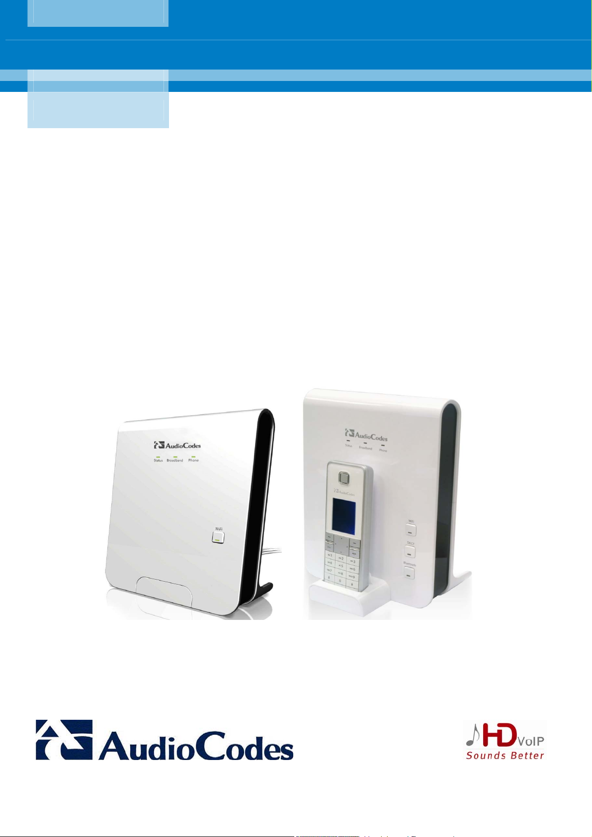
AudioCodes CPE & Access Gateway Products
MP252 Multimedia Home Gateway
User's Manual
MP252BW and MP252WDNB
MediaPack™ 252 Multimedia Home Gateway Series
Version 3.4.0
Document #: LTRT-23504
Page 6

Page 7

MP252 Multimedia Home Gateway Contents
Contents
1 Introduction .......................................................................................................20
2 Package Contents and Prerequisites..............................................................22
3 Hardware Description.......................................................................................23
3.1 Physical Description............................................................................................... 23
3.1.1 Front Panel ..............................................................................................................23
3.1.1.1 Front-Panel Buttons Description ............................................................. 24
3.1.1.2 Front-Panel LEDs Description................................................................. 25
3.1.2 Rear Panel...............................................................................................................26
3.1.2.1 Rear-Panel Port Description ................................................................... 27
3.1.2.2 Rear-Panel LEDs Description ................................................................. 28
3.2 Cabling...................................................................................................................29
3.3 Mounting ................................................................................................................ 30
Part I: Gateway Configuration................................................................................33
4 Getting Started with the Web Interface ........................................................... 35
4.1 Logging in to the Web Interface ............................................................................. 35
4.2 Menu Bar Description.............................................................................................36
4.3 Managing Tables....................................................................................................39
4.4 Configuring Users .................................................................................................. 40
4.5 Defining Associated Elements ............................................................................... 43
4.5.1 Defining Scheduler Rules ........................................................................................43
4.5.2 Defining Network Objects ........................................................................................46
4.5.3 Defining Protocols....................................................................................................47
4.6 Logging out the Web Interface...............................................................................49
5 Viewing a Graphical Display of the MP252 Network ......................................50
6 Configuring Computers for Connecting to the MP252 Network....................54
6.1 Wired Computers ................................................................................................... 54
6.1.1 Configuring Computers Running on Windows XP...................................................54
6.1.2 Configuring Computers Running on Linux...............................................................55
6.2 Connecting PC to MP252 Wireless Networks........................................................ 56
7 Connecting MP252 to the Internet ...................................................................57
7.1 Quickly Setting up an Internet Connection in the Web Interface............................57
7.1.1 WAN Ethernet..........................................................................................................58
7.1.1.1 Manual IP Address Ethernet Connection................................................ 59
7.1.1.2 Automatic IP Address Ethernet Connection............................................ 59
7.1.1.3 PPPoE..................................................................................................... 60
7.1.1.4 PPTP ....................................................................................................... 60
7.1.1.5 L2TP........................................................................................................ 61
7.1.2 WAN DSL ................................................................................................................62
7.1.2.1 PPPoE..................................................................................................... 62
7.1.2.2 PPPoA..................................................................................................... 63
7.1.2.3 Routed ETHoA ........................................................................................ 63
7.1.2.4 Bridged ETHoA ....................................................................................... 64
7.1.2.5 CLIP......................................................................................................... 64
7.2 Using the Automatic Dialer for Internet Connection...............................................66
7.2.1 Recommended Configuration..................................................................................66
7.2.2 Setting up and Starting the Automatic Dialer...........................................................68
Version 3.4.0 3 June 2011
Page 8

User's Manual
7.2.3 Quitting Automatic Dialer for Manual Configuration ................................................69
8 Configuring VoIP Parameters ..........................................................................70
8.1 Configuring the SIP Signaling Protocol..................................................................71
8.1.1 Configuring Proxy Redundancy...............................................................................77
8.2 Configuring Dialing Parameters ............................................................................. 79
8.2.1 Syntax for Digit Maps and Dial Plans ......................................................................81
8.3 Configuring Media Streaming.................................................................................83
8.3.1 Configuring Codecs .................................................................................................84
8.3.1.1 Supported Codecs................................................................................... 84
8.3.1.2 Packetization Time .................................................................................. 84
8.4 Configuring Voice and Fax..................................................................................... 84
8.5 Configuring Supplementary Services..................................................................... 88
8.6 Configuring Line Settings.......................................................................................92
8.7 Configuring Line Extensions .................................................................................. 95
8.8 Configuring Speed Dialing ..................................................................................... 96
8.9 Enabling Polarity Reversal.....................................................................................97
8.10 Selecting Regional Settings for Analog Lines ........................................................ 98
9 Connecting MP252 to an ITSP..........................................................................99
9.1 Opening a SIP Account.......................................................................................... 99
9.2 Configuring VoIP Parameters ................................................................................ 99
10 Making VoIP Calls with your Analog Telephones.........................................101
10.1 Making a Call .......................................................................................................101
10.2 Answering a Waiting Call ..................................................................................... 101
10.3 Placing a Call on Hold.......................................................................................... 102
10.4 Transferring a Call................................................................................................ 102
10.5 Establishing a 3-Way Conference Call................................................................. 103
10.6 Forwarding Calls to another Phone...................................................................... 104
11 Quality of Service............................................................................................105
11.1 QoS Wizard..........................................................................................................106
11.2 Traffic Shaping..................................................................................................... 107
11.2.1 Device Traffic Shaping.......................................................................................... 107
11.2.2 Shaping Classes................................................................................................... 109
11.2.2.1 Class Rules ........................................................................................... 110
11.3 Traffic Priority ....................................................................................................... 112
11.4 DSCP Mapping ....................................................................................................115
11.5 802.1p Mapping ...................................................................................................118
11.6 Class Statistics..................................................................................................... 119
11.7 Configuring Basic VoIP QoS ................................................................................ 120
12 Network Connections .....................................................................................123
12.1 Configuring a WAN Connection ........................................................................... 123
12.1.1 WAN DSL Connections ........................................................................................ 125
12.1.1.1 Determine Protocol Type Automatically (PVC Scan)............................ 125
12.1.1.2 PPPoE................................................................................................... 126
12.1.1.3 PPPoA................................................................................................... 128
12.1.1.4 Routed ETHoA or Bridged ETHoA........................................................ 130
12.1.1.5 CLIP....................................................................................................... 132
MP252 Multimedia Home Gateway 4 Document #: LTRT-23504
Page 9

MP252 Multimedia Home Gateway Contents
12.1.1.6 IPoA....................................................................................................... 134
12.1.2 WAN Ethernet Connections.................................................................................. 135
12.1.2.1 External DSL Modem using PPPoE...................................................... 135
12.1.2.2 External Cable Modem without Authentication ..................................... 136
12.1.2.3 External Cable Modem with PPTP........................................................ 137
12.1.2.4 External Cable Modem with L2TP......................................................... 139
12.1.2.5 DHCP .................................................................................................... 141
12.1.2.6 Manual IP Address................................................................................ 142
12.2 LAN Connection ................................................................................................... 143
12.2.1 Wireless LAN ........................................................................................................ 143
12.2.1.1 Enabling and Disabling the Wireless Network ...................................... 145
12.2.1.2 Configuring Wireless Properties under the Settings Tab...................... 145
12.2.1.3 Configuring Wireless Properties under the Wireless Tab ..................... 147
12.2.1.4 Advanced Tab ....................................................................................... 158
12.2.2 LAN Hardware Ethernet Switch............................................................................ 158
12.2.2.1 Settings Tab .......................................................................................... 159
12.2.2.2 Switch Tab............................................................................................. 160
12.2.2.3 Advanced Tab ....................................................................................... 162
12.3 Editing Network Connections and Advanced Configuration................................. 162
12.3.1 General Tab.......................................................................................................... 163
12.3.2 Settings Tab.......................................................................................................... 163
12.3.2.1 Internet Protocol Settings...................................................................... 165
12.3.3 Routing Tab .......................................................................................................... 168
12.3.4 Wireless Tab......................................................................................................... 169
12.3.5 Switch Tab ............................................................................................................ 169
12.3.6 Bridging Tab ......................................................................................................... 169
12.3.7 PPP Tab ............................................................................................................... 170
12.3.8 PPTP tab .............................................................................................................. 171
12.3.9 Advanced Tab....................................................................................................... 172
12.4 VLAN Settings......................................................................................................173
12.4.1 Settings Tab.......................................................................................................... 175
12.4.1.1 IP Address Distribution.......................................................................... 176
12.4.2 Routing Tab .......................................................................................................... 178
12.4.3 Advanced Tab....................................................................................................... 179
12.5 LAN-WAN Bridge Settings ................................................................................... 180
12.5.1 Editing LAN-WAN Bridging................................................................................... 182
13 Remote MP252 Management..........................................................................185
13.1 Overview .............................................................................................................. 185
13.1.1 Remote Configuration........................................................................................... 185
13.1.2 Remote Management ........................................................................................... 186
13.1.2.1 Firmware Upgrade................................................................................. 187
13.1.2.2 Status and Performance Monitoring...................................................... 188
13.1.2.3 Alarms, Notifications and Logging......................................................... 189
13.2 Enabling Remote Management............................................................................ 189
13.3 Securing Remote Management with Certificates ................................................. 192
13.4 Remote Configuration and Management Interfaces ............................................197
13.4.1 Embedded Web Server ........................................................................................ 197
13.4.2 TR-069 and TR-104 CPE WAN Management Protocol ....................................... 198
13.4.2.1 Configuring MP252 via TR-069 and TR-104......................................... 199
13.4.2.2 Monitoring MP252 Status via TR-069 and TR-104 ............................... 207
13.4.2.3 Security Concerns and Measures......................................................... 211
13.4.3 SNMP.................................................................................................................... 212
13.4.3.1 Enabling SNMP in the Web Interface.................................................... 212
13.4.3.2 Configuring MP252 via SNMP .............................................................. 213
13.4.3.3 Status Monitoring of System and Network Interfaces via SNMP.......... 214
Version 3.4.0 5 June 2011
Page 10

User's Manual
13.4.3.4 Security Concerns and Measures......................................................... 214
13.4.4 Syslog ................................................................................................................... 215
13.4.5 Automatic File Download...................................................................................... 215
13.4.5.1 Firmware File Download........................................................................ 215
13.4.5.2 Configuration File Download................................................................. 215
13.4.5.3 Security Concerns and Measures......................................................... 216
13.4.6 Telnet CLI ............................................................................................................. 216
14 Security............................................................................................................217
14.1 General Security Level Settings...........................................................................218
14.2 Access Control..................................................................................................... 220
14.3 Port Forwarding.................................................................................................... 221
14.4 DMZ Host ............................................................................................................. 226
14.5 Port Triggering .....................................................................................................227
14.6 Website Restrictions ............................................................................................229
14.7 NAT ...................................................................................................................... 232
14.8 Connections ......................................................................................................... 236
14.9 Advanced Filtering ...............................................................................................237
14.10Security Log ......................................................................................................... 240
15 Advanced Networking Features.....................................................................243
15.1 IP Address Distribution......................................................................................... 243
15.1.1 DHCP Server Parameters .................................................................................... 245
15.1.2 DHCP Relay Parameters...................................................................................... 246
15.1.3 Viewing DHCP Clients.......................................................................................... 247
15.1.4 Defining Static DHCP Clients ............................................................................... 247
15.2 DNS Server .......................................................................................................... 249
15.3 Dynamic DNS....................................................................................................... 250
15.4 Routing................................................................................................................. 253
15.4.1 Managing Routing Table Rules ............................................................................ 253
15.4.2 Routing Protocols ................................................................................................. 254
15.5 PPPoE Relay .......................................................................................................254
16 Home Media.....................................................................................................257
16.1 Universal Plug and Play ....................................................................................... 257
16.1.1 Enabling UPnP on MP252.................................................................................... 257
16.1.2 Adding UPnP-enabled PC to Home Network....................................................... 258
16.1.3 Monitoring Connection between MP252 and Internet .......................................... 258
16.1.4 Making Local Services available to PCs on Internet ............................................ 259
17 Add-On Servers and Disk Management........................................................263
17.1 External File Server.............................................................................................. 263
17.1.1 Automatic File Sharing.......................................................................................... 264
17.2 Disk Management ................................................................................................ 265
17.2.1 Disk Partitions....................................................................................................... 267
17.2.1.1 Connecting a Mass Storage Device...................................................... 267
17.2.1.2 Formatting a Partition............................................................................ 271
17.2.1.3 Checking a Partition.............................................................................. 272
17.2.1.4 Deleting a Partition................................................................................ 272
17.2.2 System Storage Area............................................................................................ 273
17.2.3 RAID Management ............................................................................................... 275
17.2.3.1 Creating a RAID Device........................................................................ 275
17.2.3.2 Using a RAID Device............................................................................. 277
MP252 Multimedia Home Gateway 6 Document #: LTRT-23504
Page 11

MP252 Multimedia Home Gateway Contents
17.2.3.3 Maintaining a RAID Device ................................................................... 277
17.2.3.4 Replacing RAID Underlying Devices..................................................... 277
17.3 Print Server .......................................................................................................... 279
17.3.1 Connecting and Setting up a Printer on Windows................................................ 280
17.3.2 Print Protocols ...................................................................................................... 281
17.3.2.1 Internet Printing Protocol....................................................................... 281
17.3.2.2 Microsoft Shared Printing (Samba)....................................................... 290
17.3.2.3 Line Printer Daemon (LPD)................................................................... 293
17.3.3 Storing and Using Printer Drivers ......................................................................... 300
18 Maintenance ....................................................................................................302
18.1 About MP252 .......................................................................................................302
18.2 Date & Time ......................................................................................................... 303
18.3 Backup and Restore............................................................................................. 305
18.3.1 Backing Up Data................................................................................................... 305
18.3.2 Restoring Your Data ............................................................................................. 307
18.4 Configuration File................................................................................................. 308
18.4.1 Uploading from PC on the Network...................................................................... 310
18.4.2 Uploading from a Remote Server......................................................................... 312
18.4.3 Encrypting a Configuration File Using CLI............................................................ 313
18.4.4 Automatic Upload using SIP NOTIFY Message................................................... 315
18.5 Firmware Upgrade ...............................................................................................315
18.5.1 Upgrading from a Computer on the Network........................................................ 317
18.5.2 Upgrading From the Internet ................................................................................ 319
18.6 System Settings ................................................................................................... 321
18.7 Reboot.................................................................................................................. 324
18.8 Restoring Factory Settings...................................................................................325
19 Diagnostics and Performance Monitoring....................................................326
19.1 Diagnostics...........................................................................................................326
19.1.1 Running a Ping Test ............................................................................................. 327
19.1.2 Running an ARP Test........................................................................................... 328
19.1.3 Running a Traceroute........................................................................................... 328
19.1.4 Running a PVC Scan Test.................................................................................... 329
19.1.5 Running an OAM Ping Test.................................................................................. 329
19.2 Performance Monitoring.......................................................................................331
19.2.1 Network Connections............................................................................................ 331
19.2.2 System Log........................................................................................................... 332
19.2.3 CPU ...................................................................................................................... 332
19.2.4 Voice over IP ........................................................................................................ 335
19.2.5 Internet Connection Utilization.............................................................................. 335
Part II: DECT Phone...............................................................................................337
20 Introduction .....................................................................................................338
21 Safety Instructions..........................................................................................339
22 Getting Started ................................................................................................340
22.1 Installing the DECT Phone...................................................................................340
22.2 Powering the Handset..........................................................................................341
22.2.1 Charging the Handset........................................................................................... 341
22.2.2 Checking the Battery Level................................................................................... 342
22.2.3 Switching the Base Unit On or Off........................................................................ 342
22.2.4 Switching the Handset On or Off .......................................................................... 342
Version 3.4.0 7 June 2011
Page 12

User's Manual
22.2.5 Replacing the Batteries......................................................................................... 343
22.3 Getting to Know Your Phone................................................................................ 344
22.3.1 Overview of the Handset ...................................................................................... 344
22.3.2 Getting to Know your Handset LCD Screen......................................................... 347
22.3.2.1 Menu Structure...................................................................................... 348
22.3.2.2 Entering Text and Digits........................................................................ 349
22.3.3 Viewing Base Unit Status with DECT LED........................................................... 351
22.4 Upgrading MP252 and the Base Unit................................................................... 351
22.5 Defining the MP252 Handset Line .......................................................................352
22.6 Registering the Handset to Base Unit .................................................................. 354
22.7 Checking the Handset Signal Strength ................................................................ 355
23 General Phone Operation...............................................................................356
23.1 Making an External Call ....................................................................................... 356
23.1.1 Pre-dialing............................................................................................................. 356
23.1.2 Direct Dialing ........................................................................................................ 356
23.1.3 Calling from your Phonebook ............................................................................... 356
23.1.4 Calling from the Call List....................................................................................... 356
23.1.5 Establishing a Second Call................................................................................... 356
23.1.6 Redialing a Number.............................................................................................. 357
23.2 Answering a Call .................................................................................................. 357
23.3 Answering or Rejecting a Second Call.................................................................358
23.4 Ending a Call........................................................................................................358
23.5 Adjusting Earpiece and Speakerphone Volume during a Call .............................358
23.6 Muting a Call ........................................................................................................ 358
23.7 Turning Off the Ringer.......................................................................................... 359
23.8 Redial List ............................................................................................................359
23.8.1 Saving a Redial Number to the Phonebook ......................................................... 359
23.8.2 Deleting a Number from the Redial List................................................................ 360
23.8.3 Deleting the Entire Redial List .............................................................................. 360
23.9 Locking the Keypad.............................................................................................. 360
23.10Paging the Handset.............................................................................................. 360
23.11Call Handling for Multiple, Registered Handsets.................................................. 361
23.11.1Calling (Intercom) Another Handset ..................................................................... 361
23.11.2Transferring an External Call to Another Handset................................................ 361
23.11.2.1Announced Call Transfer ...................................................................... 361
23.11.2.2Unannounced Call Transfer .................................................................. 361
23.11.3Transferring an External Call to Another External Call......................................... 362
23.11.4Toggling between External and Internal Calls...................................................... 362
23.11.5Three-Way Conference Calls ............................................................................... 363
23.11.5.1Making a Three-Way Conference Call with Another Handset and an
External Party ....................................................................................................... 363
23.11.5.2Making a Three-Way Conference Call with your Handset and two External
Calls 364
24 Phonebook.......................................................................................................365
24.1 Adding a New Contact .........................................................................................365
24.2 Editing a Contact.................................................................................................. 366
24.3 Viewing Contacts .................................................................................................366
24.4 Deleting a Contact................................................................................................ 367
24.5 Deleting All Contacts............................................................................................368
25 Call List............................................................................................................369
MP252 Multimedia Home Gateway 8 Document #: LTRT-23504
Page 13

MP252 Multimedia Home Gateway Contents
25.1 Viewing the Call List............................................................................................. 369
25.2 Saving a Call List Number to the Phonebook ......................................................370
25.3 Dialing a Call List Number.................................................................................... 370
25.4 Deleting a Call List Number .................................................................................371
25.5 Deleting the Entire Call List.................................................................................. 372
26 Clock and Alarm..............................................................................................373
26.1 Date and Time...................................................................................................... 373
26.1.1 Changing the Date Format ................................................................................... 373
26.1.2 Changing the Time Format................................................................................... 373
26.1.3 Setting the Time and Date.................................................................................... 373
26.2 Alarm....................................................................................................................374
26.2.1 Setting the Alarm .................................................................................................. 375
26.2.2 Defining the Alarm Melody ................................................................................... 376
26.2.3 Disabling the Alarm............................................................................................... 376
26.2.4 Switching Off or Snoozing the Alarm.................................................................... 376
27 Customizing the Handset...............................................................................377
27.1 Adjusting Speaker and Earpiece Volume............................................................. 377
27.2 Ring Settings........................................................................................................378
27.2.1 Choosing the Internal Ringer Melody ................................................................... 378
27.2.2 Choosing the External Ringer Melody.................................................................. 378
27.2.3 Adjusting the Ringer Volume................................................................................ 379
27.3 Alert Tones...........................................................................................................379
27.3.1 Setting the Key Tone ............................................................................................ 379
27.3.2 Setting the Battery Low Tone ............................................................................... 380
27.4 Setting the Display Language .............................................................................. 380
27.5 Selecting a Wallpaper .......................................................................................... 380
27.6 Setting the Contrast Level....................................................................................381
27.7 Activating or Deactivating Automatic Answer....................................................... 381
27.8 Selecting a Base Station...................................................................................... 381
27.9 Resetting Handset to Factory Defaults ................................................................382
28 Base Settings ..................................................................................................383
28.1 Manage Handsets ................................................................................................ 383
28.1.1 Renaming the Handset......................................................................................... 383
28.1.2 De-Registering a Handset .................................................................................... 384
28.2 Changing the PIN Number ................................................................................... 385
28.3 Resetting the Base to Factory Defaults................................................................ 385
28.4 Viewing the Product Version ................................................................................ 385
28.5 Activating Nemo Mode ......................................................................................... 386
29 Factory Defaults..............................................................................................387
30 Troubleshooting..............................................................................................388
A Specifications..................................................................................................389
A.1 Gateway Specifications........................................................................................ 389
A.2 DECT (Only for MP252WDNB) ............................................................................ 392
Version 3.4.0 9 June 2011
Page 14

User's Manual
List of Figures
Figure 1-1: MP252 Typical Application..................................................................................................21
Figure 3-1: Front Panel of MP252BW ...................................................................................................23
Figure 3-2: Front Panel of MP252WDNB ..............................................................................................24
Figure 3-3: Rear Panel of MP252BW....................................................................................................26
Figure 3-4: Rear Panel of MP252WDNB...............................................................................................27
Figure 3-5: Cabling MP252....................................................................................................................29
Figure 3-6: MP 252 Wall Mount Bracket ................................................................................................31
Figure 3-7: Attaching Phone Base to Wall Mount ..................................................................................32
Figure 4-1: Login Screen ........................................................................................................................35
Figure 4-2: Typical Table Structure ........................................................................................................39
Figure 4-3: Users Screen .......................................................................................................................40
Figure 4-4: Users Settings Screen .........................................................................................................41
Figure 4-5: Group Settings Screen.........................................................................................................43
Figure 4-6: Scheduler Rules Screen ......................................................................................................43
Figure 4-7: Edit Scheduler Rule Screen.................................................................................................44
Figure 4-8: Edit Time Segment Screen ..................................................................................................45
Figure 4-9: Edit Hour Range Screen ......................................................................................................45
Figure 4-10: Network Objects Screen ....................................................................................................46
Figure 4-11: Edit Network Objects Screen .............................................................................................46
Figure 4-12: Edit Item Screen ................................................................................................................46
Figure 4-13: Advanced - Protocols.........................................................................................................47
Figure 4-14: Advanced - Protocols - Edit Service ..................................................................................48
Figure 4-15: Advanced - Protocols - Edit Service - Server Ports...........................................................48
Figure 5-1: Map View Screen (Example) ...............................................................................................51
Figure 6-1: Internet Protocol (TCP/IP) Properties Dialog Box................................................................55
Figure 6-2: Available Wireless Networks................................................................................................56
Figure 7-1: Quick Setup Screen .............................................................................................................58
Figure 7-2: Manual IP Address WAN Ethernet Connection ...................................................................59
Figure 7-3: Automatic IP Address WAN Ethernet Connection ...............................................................60
Figure 7-4: PPPoE WAN Ethernet Connection ......................................................................................60
Figure 7-5: PPTP WAN Ethernet Connection ........................................................................................61
Figure 7-6: L2TP WAN Ethernet Connection .........................................................................................61
Figure 7-7: PPPoE WAN DSL Internet Connection ...............................................................................62
Figure 7-8: PPPoA WAN DSL Internet Connection ...............................................................................63
Figure 7-9: Routed ETHoA WAN DSL Internet Connection...................................................................63
Figure 7-10: Bridged ETHoA WAN DSL Internet Connection ................................................................64
Figure 7-11: CLIP WAN DSL Internet Connection .................................................................................65
Figure 8-1: Signaling Protocol Tab Screen ............................................................................................72
Figure 8-2: Configuring Proxy Redundancy ...........................................................................................78
Figure 8-3: Dialing Tab Screen ..............................................................................................................79
Figure 8-4: Media Streaming Tab Screen ..............................................................................................83
Figure 8-5: Voice and Fax Tab Screen ..................................................................................................84
Figure 8-6: Services Tab Screen............................................................................................................88
Figure 8-7: Line Settings Tab Screen.....................................................................................................92
Figure 8-8: Line Settings Screen for a New Line....................................................................................93
Figure 8-9: Extension Settings Tab Screen............................................................................................95
Figure 8-10: Extension Settings Screen.................................................................................................95
Figure 8-11: Speed Dial Tab Screen......................................................................................................96
Figure 8-12: Speed Dial Settings Screen (Proxy Destination) ...............................................................96
Figure 8-13: Speed Dial Settings Screen (Local Line Destination)........................................................97
Figure 8-14: Speed Dial Settings Screen (Direct Call Destination)........................................................97
Figure 8-15: Telephone Interface Tab Screen .......................................................................................98
Figure 8-16: Regional Settings Screen ..................................................................................................98
Figure 9-1: Voice Over IP - Line Settings Screen ..................................................................................99
Figure 9-2: VoIP - Line Settings - Defining a New Line....................................................................... 100
Figure 11-1: QoS Wizard Tab Screen ................................................................................................. 106
Figure 11-2: Quality of Service – Traffic Shaping Screen................................................................... 108
MP252 Multimedia Home Gateway 10 Document #: LTRT-23504
Page 15

MP252 Multimedia Home Gateway Contents
Figure 11-3: Add Device Traffic Shaping Screen................................................................................ 108
Figure 11-4: Edit Device Traffic Shaping Screen ................................................................................ 108
Figure 11-5: Add Shaping Class Screen ............................................................................................. 109
Figure 11-6: Edit Shaping Class.......................................................................................................... 110
Figure 11-7: Traffic Priority Screen ..................................................................................................... 113
Figure 11-8: Add Traffic Priority Rule Screen...................................................................................... 114
Figure 11-9: DSCP Settings Screen.................................................................................................... 116
Figure 11-10: Edit DSCP Settings....................................................................................................... 117
Figure 11-11: 802.1p Settings Screen................................................................................................. 118
Figure 11-12: Class Statistics Screen ................................................................................................. 119
Figure 11-13: Edit Device Traffic Shaping........................................................................................... 121
Figure 11-14: QoS - Edit Device Traffic Shaping - Submitting the Configuration ............................... 122
Figure 12-1: Network Connections Screen ......................................................................................... 123
Figure 12-2: Connection Wizard Screen ............................................................................................. 124
Figure 12-3: WAN DSL Properties Screen.......................................................................................... 125
Figure 12-4: Determine Protocol Type Automatically (PVC Scan) Screen ......................................... 126
Figure 12-5: Scan User Defined VPI/VCI Screen ............................................................................... 126
Figure 12-6: DSL PVC Parameters Configuration Screen .................................................................. 127
Figure 12-7: Point-to-Point Protocol over Ethernet (PPPoE) Screen.................................................. 127
Figure 12-8: Connection Summary Screen ......................................................................................... 128
Figure 12-9: DSL PVC Parameters Configuration Screen .................................................................. 129
Figure 12-10: Point-to-Point Protocol over ATM (PPPoA) Screen...................................................... 129
Figure 12-11: Connection Summary Screen....................................................................................... 130
Figure 12-12: DSL PVC Parameters Configuration Screen................................................................ 131
Figure 12-13: Ethernet Connection over ATM (ETHoA) Screen......................................................... 131
Figure 12-14: Connection Summary Screen....................................................................................... 132
Figure 12-15: Classical IP over ATM (CLIP) Screen........................................................................... 133
Figure 12-16: Connection Summary Screen....................................................................................... 133
Figure 12-17: Routed IP over ATM (IPoA) Screen.............................................................................. 134
Figure 12-18: Connection Summary Screen....................................................................................... 135
Figure 12-19: Point-to-Point Protocol over Ethernet (PPPoE) Screen................................................ 135
Figure 12-20: PPPoE Connection Summary....................................................................................... 136
Figure 12-21: Internet Cable Modem Connection Screen................................................................... 136
Figure 12-22: Ethernet Connection Summary..................................................................................... 137
Figure 12-23: Internet Cable Modem Connection Screen................................................................... 138
Figure 12-24: Point-to-Point Tunneling Protocol (PPTP) Screen........................................................ 138
Figure 12-25: PPTP Connection Summary......................................................................................... 139
Figure 12-26: Internet Cable Modem Connection Screen................................................................... 139
Figure 12-27: Layer 2 Tunneling Protocol (L2TP) Screen .................................................................. 140
Figure 12-28: L2TP Connection Summary.......................................................................................... 141
Figure 12-29: Ethernet Connection Screen......................................................................................... 141
Figure 12-30: DHCP Connection Summary ........................................................................................ 142
Figure 12-31: Ethernet Connection Screen......................................................................................... 142
Figure 12-32: Manual IP Address Configuration Screen..................................................................... 142
Figure 12-33: Manual IP Connection Summary .................................................................................. 143
Figure 12-34: Network Connections Screen Displaying LAN Wireless Interface................................ 144
Figure 12-35: LAN Wireless 802.11n Access Point Properties (General Tab) Screen....................... 144
Figure 12-36: LAN Wireless 802.11 Access Point Properties (Settings Tab) Screen......................... 146
Figure 12-37: LAN Wireless 802.11 Access Point Properties (Wireless Tab) Screen........................ 147
Figure 12-38: Wireless Network Group in Wireless Tab Screen......................................................... 148
Figure 12-39: MAC Filtering Settings Screen...................................................................................... 149
Figure 12-40: MAC Address Added to MAC Filtering Table ............................................................... 149
Figure 12-41: WPS Group in Wireless Tab Screen ............................................................................ 149
Figure 12-42: Configuring WPA Security ............................................................................................ 150
Figure 12-43: Configuring WPA2 Security .......................................................................................... 151
Figure 12-44: Configuring Non-WEP Security..................................................................................... 152
Figure 12-45: Configuring Encryption Key in Windows Wireless Client.............................................. 153
Figure 12-46: Configuring Authentication Only Security ..................................................................... 153
Figure 12-47: Transmission Parameters in Wireless Tab Screen....................................................... 154
Version 3.4.0 11 June 2011
Page 16

User's Manual
Figure 12-48: Virtual APs Table .......................................................................................................... 154
Figure 12-49: New Virtual AP.............................................................................................................. 155
Figure 12-50: Firewall Blocking Access to All Other LANs ................................................................. 156
Figure 12-51: Example Virtual AP ....................................................................................................... 157
Figure 12-52: Wireless Advanced Tab ................................................................................................ 158
Figure 12-53: Network Connections Screen ....................................................................................... 159
Figure 12-54: LAN Hardware Ethernet Switch Screen........................................................................ 159
Figure 12-55: LAN Hardware Ethernet Switch Screen – Settings Tab ............................................... 159
Figure 12-56: LAN Hardware Ethernet Switch Screen – Switch Tab.................................................. 160
Figure 12-57: Port Settings Screen ..................................................................................................... 161
Figure 12-58: LAN Hardware Ethernet Switch Screen – Advanced Tab ............................................ 162
Figure 12-59: Editing Connection - General Tab (For Example, WAN Ethernet) ............................... 163
Figure 12-60: Editing Connection - Settings Tab (For Example, WAN Ethernet) ............................... 163
Figure 12-61: Automatically Obtaining an IP Address ........................................................................ 165
Figure 12-62: Manually Defining DNS Server ..................................................................................... 166
Figure 12-63: IP Address Distribution - DHCP Server ........................................................................ 167
Figure 12-64: IP Address Distribution - DHCP Relay.......................................................................... 167
Figure 12-65: DHCP Relay Server Address........................................................................................ 167
Figure 12-66: Editing Connection - Routing Tab (For Example, WAN Ethernet)................................ 168
Figure 12-67: Route Settings Screen .................................................................................................. 169
Figure 12-68: Editing Connection - PPP Tab ...................................................................................... 170
Figure 12-69: Editing Connection - PPTP Tab.................................................................................... 172
Figure 12-70: Editing Connection - Advanced Tab (For Example, WAN Ethernet) ............................ 172
Figure 12-71: Additional IP Address Settings Screen ......................................................................... 172
Figure 12-72: Connection Wizard Screen ........................................................................................... 173
Figure 12-73: Advanced Connection................................................................................................... 174
Figure 12-74: VLAN Interface.............................................................................................................. 174
Figure 12-75: Connection Summary ................................................................................................... 175
Figure 12-76: IP Address Distribution - DHCP Server ........................................................................ 176
Figure 12-77: IP Address Distribution - DHCP Relay.......................................................................... 177
Figure 12-78: DHCP Relay Server Address........................................................................................ 177
Figure 12-79: IP Address Distribution - Disable DHCP....................................................................... 177
Figure 12-80: Advanced Routing Properties ....................................................................................... 178
Figure 12-81: Internet Connection Firewall ......................................................................................... 180
Figure 12-82: Bridge Options .............................................................................................................. 180
Figure 12-83: Network Bridging Screen .............................................................................................. 181
Figure 12-84: Adding New Network Bridging ...................................................................................... 181
Figure 12-85: Connection Summary - Configure Existing Bridge ....................................................... 182
Figure 12-86: Bridging Tab.................................................................................................................. 183
Figure 12-87: VLAN Settings Screen .................................................................................................. 184
Figure 12-88: Bridge Filter Screen ...................................................................................................... 184
Figure 13-1: Remote Management Interfaces..................................................................................... 186
Figure 13-2: Firmware Upgrade Mechanism....................................................................................... 187
Figure 13-3: Remote Administration Screen ....................................................................................... 191
Figure 13-4: New Certificates Screen ................................................................................................. 192
Figure 13-5: Create Self Signed X509 Certificate Screen................................................................... 193
Figure 13-6: New Self Signed X509 Certificate Screen ...................................................................... 193
Figure 13-7: Newly Created Self-Signed Certificate ........................................................................... 193
Figure 13-8: File Download Window ................................................................................................... 194
Figure 13-9: Load MP252’s Local Certificate ...................................................................................... 194
Figure 13-10: CA's Certificates Page .................................................................................................. 194
Figure 13-11: Load CA's Certificate Page........................................................................................... 196
Figure 13-12: TR-069 CPE WAN Management Protocol.................................................................... 198
Figure 13-13: SNMP Network Architecture ......................................................................................... 212
Figure 13-14: Simple Network Management Protocol (SNMP) Screen .............................................. 213
Figure 14-1: Firewall in Action............................................................................................................. 217
Figure 14-2: General Security Level Settings...................................................................................... 218
Figure 14-3: Access Control ................................................................................................................ 220
Figure 14-4: Add Access Control Rule ................................................................................................ 220
MP252 Multimedia Home Gateway 12 Document #: LTRT-23504
Page 17

MP252 Multimedia Home Gateway Contents
Figure 14-5: Port Forwarding Screen .................................................................................................. 223
Figure 14-6: Add Port Forwarding Rule............................................................................................... 223
Figure 14-7: Selecting Protocol Type .................................................................................................. 223
Figure 14-8: Specifying Public IP Address .......................................................................................... 224
Figure 14-9: Select Check Box of Port Forwarding Rule (Active) ....................................................... 224
Figure 14-10: DMZ Host...................................................................................................................... 226
Figure 14-11: Port Triggering .............................................................................................................. 227
Figure 14-12: Adding Port Triggering Rules........................................................................................ 228
Figure 14-13: Edit Service Server Ports.............................................................................................. 228
Figure 14-14: Edit Service Server Ports.............................................................................................. 228
Figure 14-15: Edit Service Opened Ports............................................................................................ 229
Figure 14-16: New Port Triggering Rule.............................................................................................. 229
Figure 14-17: Website Restrictions ..................................................................................................... 230
Figure 14-18: Restricted Website........................................................................................................ 230
Figure 14-19: Add a Specific Host....................................................................................................... 231
Figure 14-20: Add a Specific Schedule ............................................................................................... 231
Figure 14-21: NAT Screen................................................................................................................... 233
Figure 14-22: Adding a NAT IP Address............................................................................................. 233
Figure 14-23: Adding NAT/NAPT Rule................................................................................................ 234
Figure 14-24: Connections Screen...................................................................................................... 236
Figure 14-25: Advanced Filtering ........................................................................................................ 237
Figure 14-26: Add Advanced Filter...................................................................................................... 238
Figure 14-27: Add a Specific Host....................................................................................................... 239
Figure 14-28: Set Priority Rule ............................................................................................................ 239
Figure 14-29: Security Log .................................................................................................................. 240
Figure 14-30: Security Log Settings .................................................................................................... 241
Figure 15-1: DHCP Server Summary.................................................................................................. 244
Figure 15-2: DHCP Settings Screen ................................................................................................... 245
Figure 15-3: DHCP Settings................................................................................................................ 246
Figure 15-4: DHCP Relay Server Address Screen ............................................................................. 246
Figure 15-5: DHCP Connection Screen .............................................................................................. 247
Figure 15-6: DHCP Connection Settings Screen ................................................................................ 247
Figure 15-7: DNS Server ..................................................................................................................... 250
Figure 15-8: DNS Entry ....................................................................................................................... 250
Figure 15-9: Personal Domain Name (Dynamic DNS) Screen ........................................................... 251
Figure 15-10: Personal Domain Name (Dynamic DNS) - Adding ....................................................... 251
Figure 15-11: Routing Rules................................................................................................................ 253
Figure 15-12: Route Settings Screen .................................................................................................. 253
Figure 15-13: PPPoE Relay Screen.................................................................................................... 255
Figure 16-1: Advanced - Universal Plug n Play................................................................................... 257
Figure 16-2: My Network Places ......................................................................................................... 258
Figure 16-3: Internet Connection Status ............................................................................................. 259
Figure 16-4: Internet Connection Properties ....................................................................................... 260
Figure 16-5: Advanced Settings .......................................................................................................... 260
Figure 16-6: Service Settings .............................................................................................................. 261
Figure 16-7: Service Settings – Add Service....................................................................................... 261
Figure 17-1: File Server Screen .......................................................................................................... 263
Figure 17-2: File Server Share Settings Screen.................................................................................. 264
Figure 17-3: User Screen .................................................................................................................... 265
Figure 17-4: File Server Screen with the Share .................................................................................. 265
Figure 17-5: Disk Management Screen............................................................................................... 266
Figure 17-6: Manually Defining System Storage Area ........................................................................ 267
Figure 17-7: Disk Information .............................................................................................................. 268
Figure 17-8: Partition Type.................................................................................................................. 268
Figure 17-9: Partition Size................................................................................................................... 269
Figure 17-10: Partition Format ............................................................................................................ 269
Figure 17-11: Partition File System ..................................................................................................... 269
Figure 17-12: Partition Summary ........................................................................................................ 270
Figure 17-13: Formatting Complete – Partition Ready........................................................................ 270
Version 3.4.0 13 June 2011
Page 18

User's Manual
Figure 17-14: Partition Properties ....................................................................................................... 271
Figure 17-15: Partition Format ............................................................................................................ 271
Figure 17-16: Partition Format ............................................................................................................ 272
Figure 17-17: Disk Management Screen – Check Box Cleared ......................................................... 274
Figure 17-18: RAID Properties Screen................................................................................................ 275
Figure 17-19: Partition Format Screen ................................................................................................ 276
Figure 17-20: Partition File System Screen......................................................................................... 276
Figure 17-21: Partition Summary Screen ............................................................................................ 276
Figure 17-22: Added RAID Devices .................................................................................................... 277
Figure 17-23: Advanced – Print Server Screen................................................................................... 279
Figure 17-24: Advanced – Printer Screen........................................................................................... 279
Figure 17-25: MP252 Shares .............................................................................................................. 280
Figure 17-26: Printer Screen – IPP URL ............................................................................................. 282
Figure 17-27: Local or Network Printer ............................................................................................... 282
Figure 17-28: Specify a Printer............................................................................................................ 282
Figure 17-29: Printer Screen – IPP URL ............................................................................................. 284
Figure 17-30: Linux CUPS Management ............................................................................................ 284
Figure 17-31: Add Printer .................................................................................................................... 285
Figure 17-32: Printer Name................................................................................................................. 285
Figure 17-33: Printing Protocol............................................................................................................ 286
Figure 17-34: IPP URL ........................................................................................................................ 286
Figure 17-35: Print & Fax .................................................................................................................... 287
Figure 17-36: Printer Browser – IP Printer .......................................................................................... 288
Figure 17-37: Print & Fax – New IPP Printer....................................................................................... 289
Figure 17-38: Print & Fax .................................................................................................................... 290
Figure 17-39: Printer Browser – Default Browser................................................................................ 291
Figure 17-40: Printer Browser – More Printers.................................................................................... 291
Figure 17-41: Printer Browser – MP252.............................................................................................. 292
Figure 17-42: Printer Browser – Printer Model.................................................................................... 292
Figure 17-43: Print & Fax – New Samba Printer................................................................................. 292
Figure 17-44: Local Printer.................................................................................................................. 294
Figure 17-45: Select a Printer Port...................................................................................................... 294
Figure 17-46: Add Port ........................................................................................................................ 295
Figure 17-47: Additional Port Information............................................................................................ 295
Figure 17-48: Printer Port Monitor Configuration ................................................................................ 296
Figure 17-49: Add Printer Wizard........................................................................................................ 297
Figure 17-50: Print & Fax .................................................................................................................... 298
Figure 17-51: Printer Browser – LPD Printer....................................................................................... 299
Figure 17-52: Print & Fax – New LPD Printer ..................................................................................... 300
Figure 17-53: MP252 Shares .............................................................................................................. 301
Figure 18-1: About MP252 Screen...................................................................................................... 302
Figure 18-2: Date and Time Screen .................................................................................................... 303
Figure 18-3: Time Server Settings Screen .......................................................................................... 304
Figure 18-4: Backup and Restore Screen........................................................................................... 305
Figure 18-5: Edit Backup Screen ........................................................................................................ 306
Figure 18-6: Restore Screen ............................................................................................................... 307
Figure 18-7: Configuration File Screen ............................................................................................... 308
Figure 18-8: Upload Configuration File ............................................................................................... 310
Figure 18-9: Loading Configuration File from a PC on the Network ................................................... 310
Figure 18-10: Successful Configuration File Uploading ...................................................................... 311
Figure 18-11: Upload Configuration File ............................................................................................. 312
Figure 18-12: MP252 Firmware Upgrade Screen ............................................................................... 317
Figure 18-13: Upgrade From a Computer in the Network Screen ...................................................... 318
Figure 18-14: Confirming Firmware Upgrade Screen ......................................................................... 318
Figure 18-15: Upgrading in Progress Screen...................................................................................... 318
Figure 18-16: Advanced - Firmware and Configuration Upgrade ....................................................... 319
Figure 18-17: System Settings Screen (Only Partial View due to Screen Size) ................................. 321
Figure 18-18: Reboot Screen .............................................................................................................. 324
Figure 18-19: Restore Factory Settings Screen.................................................................................. 325
MP252 Multimedia Home Gateway 14 Document #: LTRT-23504
Page 19

MP252 Multimedia Home Gateway Contents
Figure 19-1: Diagnostics Screen ......................................................................................................... 326
Figure 19-2: Running a Ping Test ....................................................................................................... 328
Figure 19-3: Running an ARP Test ..................................................................................................... 328
Figure 19-4: Running a Traceroute ..................................................................................................... 329
Figure 19-5: Running a PVC Scan ...................................................................................................... 329
Figure 19-6: Running an OAM Ping Test ............................................................................................ 330
Figure 19-7: Network Connections Screen ......................................................................................... 331
Figure 19-8: System Log Screen......................................................................................................... 332
Figure 19-9: CPU Screen .................................................................................................................... 334
Figure 19-10: VoIP Screen.................................................................................................................. 335
Figure 19-11: Internet Connection Utilization – By Computer Screen ................................................ 336
Figure 19-12: Internet Connection Utilization – By Application Screen .............................................. 336
Figure 22-1: Plastic Tab jutting out from Battery Compartment ......................................................... 340
Figure 22-2: Attaching Handset Cradle to MP252 Base Unit............................................................. 340
Figure 22-3: Handset Charging in Cradle........................................................................................... 341
Figure 22-4: Installing Batteries.......................................................................................................... 343
Figure 22-5: Areas of the Handset ..................................................................................................... 344
Figure 22-6: Areas of the Handset LCD Screen................................................................................. 347
Figure 22-7: Handset Keypad ............................................................................................................ 350
Version 3.4.0 15 June 2011
Page 20

User's Manual
List of Tables
Table 1-1: MP252 Available Models.......................................................................................................20
Table 3-1: Front-Panel Buttons Description ...........................................................................................24
Table 3-2: Front-Panel LEDs Description...............................................................................................25
Table 3-3: Front-Panel LED Descriptions for Automatic Dialer Feature ................................................26
Table 3-4: Rear-Panel Ports Description................................................................................................27
Table 3-5: Rear-Panel LEDs Description ...............................................................................................28
Table 4-1: Menu Description ..................................................................................................................36
Table 4-2: Table Action Icons Description..............................................................................................39
Table 5-1: Map View Icon Description....................................................................................................52
Table 8-1: Signaling Protocol Tab Parameters Description ...................................................................72
Table 8-2: Dialing Tab Parameters Description .....................................................................................80
Table 8-3: Dial Plan (for Left of '=' Sign) and Digit Map Syntax .............................................................82
Table 8-4: Media Streaming Tab Parameters Description .....................................................................83
Table 8-5: Voice and Fax Tab Parameters Description .........................................................................86
Table 8-6: Services Tab Parameters Description ..................................................................................89
Table 12-1: Wireless Tab – Basic Wireless Access Point Parameters Description............................ 148
Table 12-2: Settings Tab - Parameter Descriptions ............................................................................ 164
Table 12-3: Routing Parameters ......................................................................................................... 168
Table 12-4: PPP Tab Parameter Descriptions .................................................................................... 170
Table 12-5: PPTP Tab Parameter Descriptions.................................................................................. 172
Table 12-6: VLAN Interface - General Communication Parameters................................................... 175
Table 12-7: IP Address Distribution Parameters................................................................................. 176
Table 12-8: DHCP Relay..................................................................................................................... 177
Table 12-9: Assigning Static IP Addresses to Network Computers .................................................... 177
Table 12-10: Routing Parameters ....................................................................................................... 179
Table 13-1: Main Configuration Parameter Groups ............................................................................ 186
Table 13-2: Status and Performance Monitoring Parameters............................................................. 188
Table 13-3: Notifications and Logged Events...................................................................................... 189
Table 13-4: Severity of Logged Events ............................................................................................... 189
Table 13-5: Operations per Configuration/Management Interface...................................................... 197
Table 13-6: InternetGatewayDevice.WANDevice.i.WANConnectionDevice.i.WANIPConnection.i.... 199
Table 13-7: InternetGatewayDevice.LANDevice.i.LANEthernetInterfaceConfig................................. 200
Table 13-8: InternetGatewayDevice.LANDevice.i.LANHostConfigManagement................................ 202
Table 13-9: InternetGatewayDevice.Services.VoiceService.i.Capabilities ......................................... 203
Table 13-10: InternetGatewayDevice.Services.VoiceService.i.Capabilities.Codecs.......................... 205
Table 13-11: InternetGatewayDevice.Services.VoiceService.i.VoiceProfile....................................... 206
Table 13-12: InternetGatewayDevice.Services.VoiceService.i.VoiceProfile.i.SIP .............................. 206
Table 13-13: InternetGatewayDevice.DeviceInfo................................................................................ 207
Table 13-14: InternetGatewayDevice.WANDevice.i.WANConnectionDevice.i.
WANIPConnection.i.Stats.................................................................................................................... 209
Table 13-15: InternetGatewayDevice.LANDevice.i.LANEthernetInterfaceConfig.i.Stats ................... 209
Table 13-16: InternetGatewayDevice.Services.VoiceService.i.VoiceProfile.i.Line.i.Stats .................. 210
Table 13-17: Table 3-13: Information Elements Available via MIB-II.................................................. 214
Table 14-1: Behavior for the Three Security Levels............................................................................ 219
Table 17-1: IPP, Samba, and LPD Specifications............................................................................... 281
Table 22-1: Handset Description......................................................................................................... 345
Table 22-2: Handset LCD Icon Descriptions....................................................................................... 347
Table 22-3: Handset LCD Menus and Submenus .............................................................................. 348
Table 22-4: Handset LCD Menus and Submenus Accessed using Navigation Keys......................... 349
Table 22-5: DECT LED Description .................................................................................................... 351
Table 22-6: About MP252 Screen ....................................................................................................... 352
Table 22-7: Line Settings Screen ........................................................................................................ 353
Table 22-8: Defining Line 3 Properties................................................................................................ 353
Table 29-1: Factory Defaults ............................................................................................................... 387
Table 30-1: Troubleshooting ............................................................................................................... 388
Table A-1: MP252 Router and VoIP Software Specifications ............................................................. 389
Table A-2: MP252WDNB DECT Phone Specifications....................................................................... 392
MP252 Multimedia Home Gateway 16 Document #: LTRT-23504
Page 21

MP252 Multimedia Home Gateway Notices
Notice
This document describes the installation and configuration of AudioCodes MP252BW and
MP252WDNB MediaPack™ 252 Multimedia Home Gateway series Version 3.4.0.
Information contained in this document is believed to be accurate and reliable at the time of
printing. However, due to ongoing product improvements and revisions, AudioCodes cannot
guarantee accuracy of printed material after the Date Published nor can it accept responsibility
for errors or omissions. Updates to this document and other documents as well as software files
can be viewed by registered customers at http://www.audiocodes.com/downloads.
© 2011 AudioCodes Inc. All rights reserved
This document is subject to change without notice.
Date Published: May-30-2011
Trademarks
AudioCodes, AC, AudioCoded, Ardito, CTI2, CTI², CTI Squared, HD VoIP, HD VoIP Sounds
Better, InTouch, IPmedia, Mediant, MediaPack, NetCoder, Netrake, Nuera, Open Solutions
Network, OSN, Stretto, TrunkPack, VMAS, VoicePacketizer, VoIPerfect, VoIPerfectHD,
What’s Inside Matters, Your Gateway To VoIP and 3GX are trademarks or registered
trademarks of AudioCodes Limited. All other products or trademarks are property of their
respective owners.
WEEE EU Directive
Pursuant to the WEEE EU Directive, electronic and electrical waste must not be disposed of
with unsorted waste. Please contact your local recycling authority for disposal of this product.
Customer Support
Customer technical support and service are generally provided by AudioCodes’ Distributors,
Partners, and Resellers from whom the product was purchased. For technical support for
products purchased directly from AudioCodes, or for customers subscribed to AudioCodes
Customer Technical Support (ACTS), contact support@audiocodes.com
Abbreviations and Terminology
Each abbreviation, unless widely used, is spelled out in full when first used. When the term
'device' is used, it refers to MP252.
Regulatory Information
The Regulatory Information can be viewed at www.audiocodes.com/library.
.
Version 3.4.0 17 July 2011
Page 22
User's Manual
Related Documentation
Document Name
Demo Guide
Multimedia Home Gateway Quick Guide
Release Notes
Routing Performance Technical Application Note
Safety Warnings
Note: Open source software may have been added and/or amended for this product.
For further information please visit our website at:
http://audiocodes.com/support or contact your AudioCodes sales
representative.
Warning: Before connecting MP252 to power:
• Use only the AC/DC power adapter supplied with MP252. Do not use any
other power adapter. This power adapter is a 12 VDC +/-10%, tolerance,
2A, limited power source wall-mount Class II power supply adapter.
• Ensure that the VAC ratings match.
• Ensure that you have read the Regulatory Information, obtained from
www.audiocodes.com/library.
MP252 Multimedia Home Gateway 18 Document #: LTRT-23504
Page 23

MP252 Multimedia Home Gateway 1. Introduction
For Customers in Canada
This Class [B] digital apparatus complies with Canadian ICES-003.
Cet appareil numérique de la classe [B] est conforme à la norme NMB-003 du Canada.
Operation is subject to the following two conditions: (1) this device may not cause interference,
and (2) this device must accept any interference, including interference that may cause
undesired operation of the device.
This device and its antenna(s) must not be co-located or operating in conjunction with any other
antenna or transmitter.
The County Code Selection feature is disabled for products marketed in the US/Canada.
IC Radiation Exposure Statement
This equipment complies with IC RSS-102 radiation exposure limits set forth for an uncontrolled
environment. This equipment should be installed and operated with minimum distance of 20 cm
between the radiator and your body.
Version 3.4.0 19 June 2011
Page 24

User's Manual
1 Introduction
The MediaPack™ 252 (MP252) is a sophisticated, feature-rich, multimedia home gateway
for broadband networks with multi-play support. With ADSL2+ modem, multiple antenna
wireless LAN connectivity, Digital Enhanced Cordless Telecommunications (DECT)
handsets supporting High Definition (HD) Voice-over-IP (VoIP), and optional battery backup,
this is a true all-in-one gateway for Multi-play services.
The MP252 is ideal for operators, seeking new revenue generators with state-of- the-art
features, such as:
ADSL/ADSL2+ modem, up to 24 Mbps
10/100 Ethernet WAN port (optional connection to cable modem or FTTH ONU)
Optional ADSL WAN backup using 3G USB dongles
HD VoIP telephony and PBX capabilities, including flexible configuration of individual
SIP accounts per DECT extension
Four 10/100 Ethernet LAN ports
High-speed wireless network (802.11 b/g/n), up to 150 Mbps
Router, Firewall, NAT and advanced traffic prioritization mechanisms
2 FXS ports for analog phones and fax machines
Guaranteed Quality of Service (QoS) for IPTV service
Print server and File server, accessible from every computer on the home network
Advanced TR-069 management, interoperable with leading Auto-Configuration Servers
(ACS)
Optional battery backup for up to 4 hours standby
The MP252 is based on AudioCodes’ MP-2xx line of Residential Gateways and AudioCodes
VoIPerfect™ software architecture. The MP252 is interoperable with various softswitches
and supports advanced TR-069 management, working with market leading
Auto-Configuration Servers (ACS). Other management tools, such as a friendly HTTP-based
Web GUI, and Command Line Interface (CLI) are also available.
The MP252 is available in the following models:
Table 1-1: MP252 Available Models
Model ADSL + 4 LAN Wi-Fi 802.11n DECT HD VoIP VoIP 2 FXS USB 2.0
MP252BW
MP252WDNB
Note: All DECT and PBX--related functionalities are supported only by the
MP252 Multimedia Home Gateway 20 Document #: LTRT-23504
√ √ - √ 1
√ √ √ √ 3
MP252WDNB.
Page 25
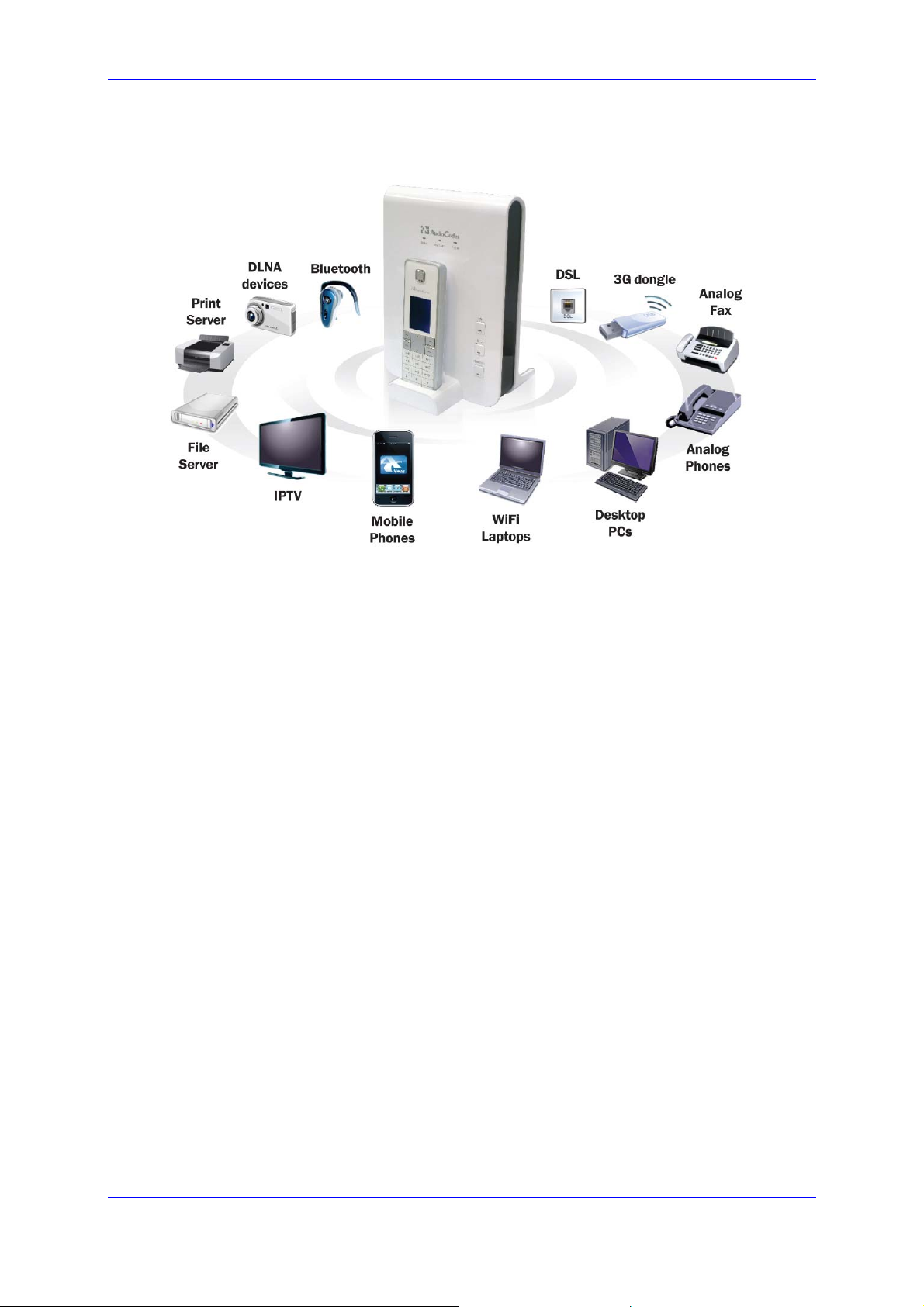
MP252 Multimedia Home Gateway 1. Introduction
The figure below illustrates the typical applications supported by MP252:
Figure 1-1: MP252 Typical Application
Version 3.4.0 21 June 2011
Page 26

User's Manual
2 Package Contents and Prerequisites
The MP252 is shipped with the following items:
1 x RJ-11 telephone cable
1 x RJ-45 Ethernet cable
12V AC/DC power adaptor (use only supplied)
DECT handset and cradle
Make sure that all these items are included. If any items are missing, contact your sales
representative.
The following prerequisites are required (not supplied by AudioCodes):
A broadband Internet connection
ADSL cable (if required)
Analog telephones
Additional RJ-11 telephone cable (if required)
Additional RJ-45 Ethernet cables (if required)
MP252 Multimedia Home Gateway 22 Document #: LTRT-23504
Page 27
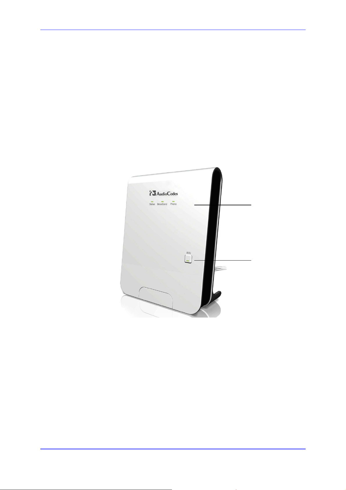
MP252 Multimedia Home Gateway 3. Hardware Description
3 Hardware Description
This section describes the physical description and cabling of the MP252. This includes both
models (i.e., MP252BW and MP252WDNB).
3.1 Physical Description
The MP252 provides ports, buttons, and LEDs on its front and rear panels.
3.1.1 Front Panel
The front panel provides LEDs for displaying various operating status and button(s) for
activating various features such as Wi-Fi. For more information on the LEDs, see Section
3.1.1.2 on page 25. For more information on the buttons, see Section 3.1.1.1 on page 24.
The figures below display the front panels of the MP252 models.
Figure 3-1: Front Panel of MP252BW
LEDs
WiFi Button
Version 3.4.0 23 June 2011
Page 28
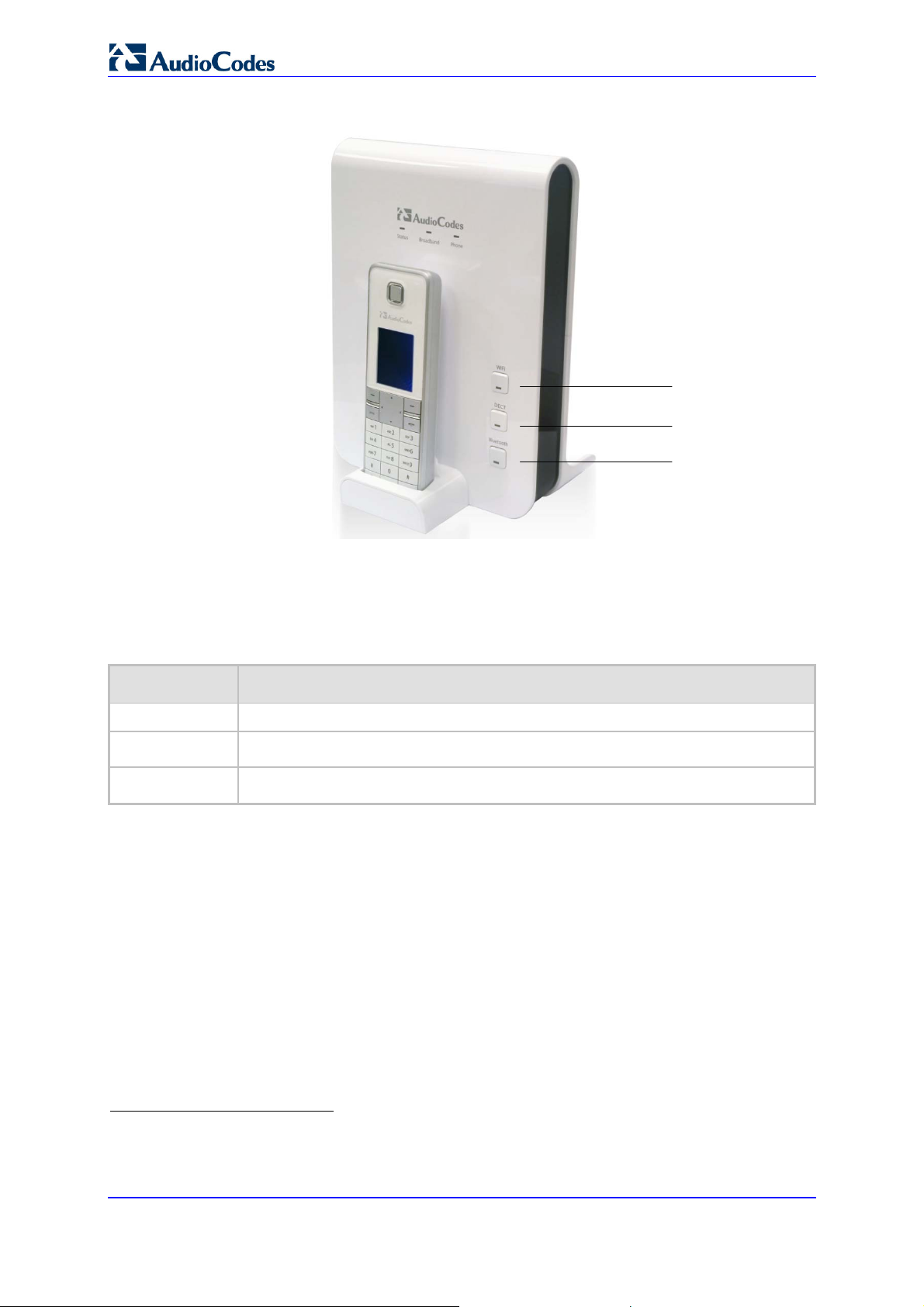
User's Manual
Figure 3-2: Front Panel of MP252WDNB
WiFi Button
DECT Button
Bluetooth
Button
3.1.1.1 Front-Panel Buttons Description
The button(s) on the front panel are described in the table below:
Table 3-1: Front-Panel Buttons Description
Label Description
WiFi
Dect1
Bluetooth2
Activates or deactivates Wi-Fi connectivity (802.11 b/g/n).
Registers the handset to the MP252 base unit.
Currently not supported.
1
This button is available only on the MP252WDNB model.
2
This button is available only on the MP252WDNB model.
MP252 Multimedia Home Gateway 24 Document #: LTRT-23504
Page 29
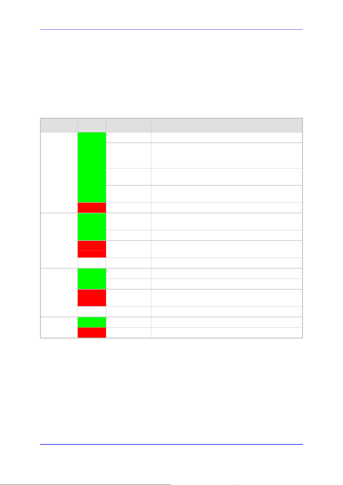
MP252 Multimedia Home Gateway 3. Hardware Description
3.1.1.2 Front-Panel LEDs Description
The LEDs on the front panel are described for general functionality and for the Automatic
Dialer feature.
3.1.1.2.1 General Description
The general description of the MP252 front-panel LEDs are described in the table below:
Table 3-2: Front-Panel LEDs Description
LED Color State Description
Status
Broadband
Phone
Green
Red
Green
Red
- Off WAN Ethernet cable is not connected – no WAN link
Green
Red
On Device start-up successful
Slow Blinking Software upgrade in progress.
Note: During software upgrade, the Broadband and Phone
LEDs also blink green.
Slow Blinking Battery backup is in use and there is no power from the AC
electrical outlet.
Fast Blinking Battery is low and there is no power from the AC electrical
outlet.
On Reboot (automatic, by default) or indicates a problem
On WAN port is successfully connected and IP address
acquired successfully
Blinking Software upgrade in process
On WAN IP address has not yet been acquired from the ISP
(i.e. in the process of acquiring or has failed to acquire).
On All configured phones are registered to the Proxy server
Blinking Software upgrade in process
On At least one of the phones failed to register to the Proxy
server
- Off No Proxy server is configured
WiFi
Version 3.4.0 25 June 2011
Green
Red
On Wi-Fi is enabled and active
Off Wi-Fi is disabled
Page 30
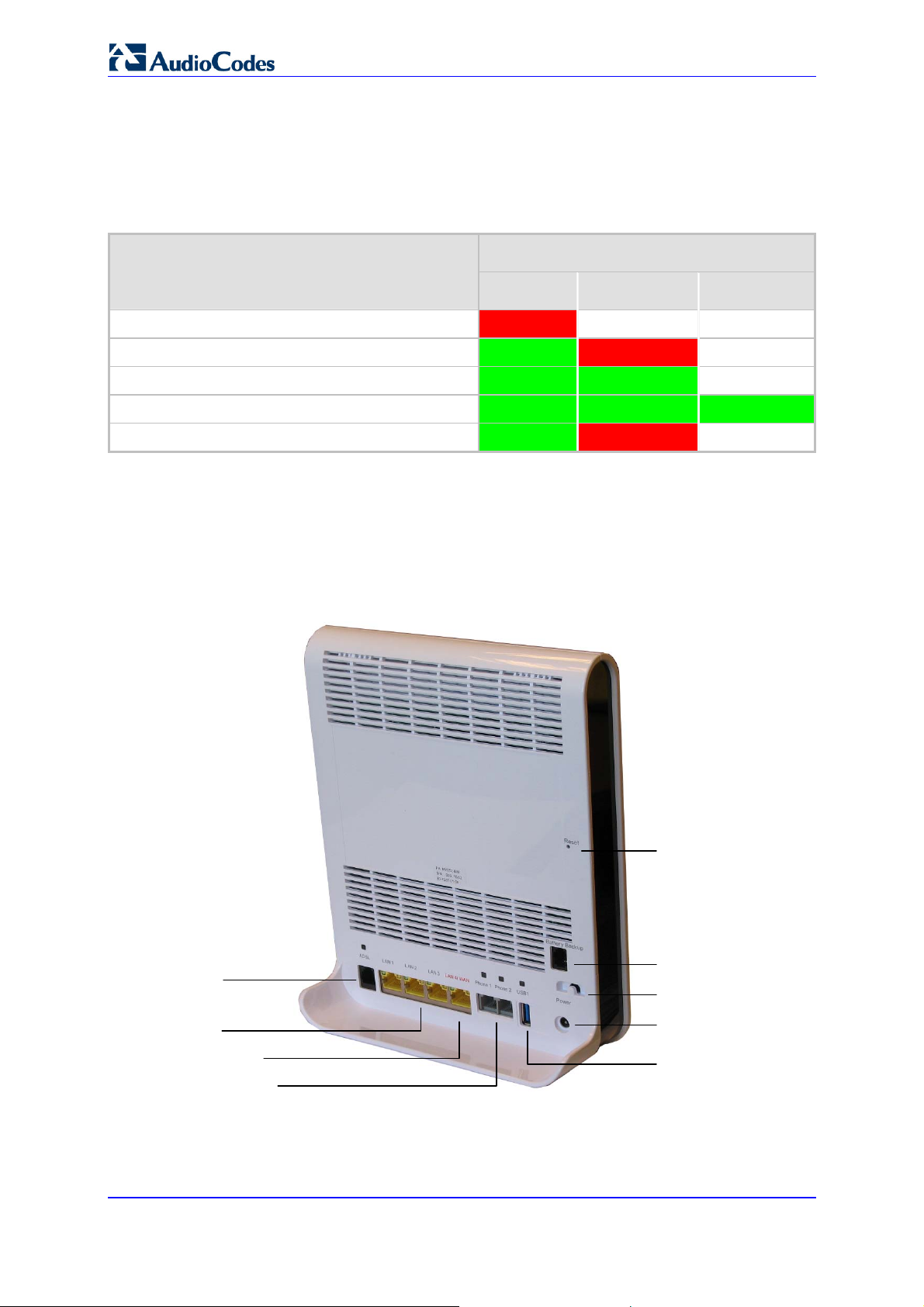
User's Manual
3.1.1.2.2 Automatic Dialer Feature
The table below describes the front-panel LEDs behavior when the Automatic Dialer feature
is used (described in detail in Section 7.2).
Table 3-3: Front-Panel LED Descriptions for Automatic Dialer Feature
LED Stage
Status Broadband Phone
During boot Red Off Off
Before WAN physical link detection Green Blinking Red Off
During automatic dialer operation Green Blinking Green Off
Automatic dialer success Green Green Green*
Automatic dialer failure Green Red Off
* The Phone LED lights green only after MP252 connects to the Internet, downloads its
configuration file, and then registers to the VoIP service.
3.1.2 Rear Panel
The rear panel provides the ports for connecting the various interfaces. The figures below
display the rear panels of the MP252 models.
ADSL Port
Figure 3-3: Rear Panel of MP252BW
Reset Button
Battery Backup Port
Power Button
LAN Ports
LAN/WAN Port
FXS Phone Ports
MP252 Multimedia Home Gateway 26 Document #: LTRT-23504
Power Plug
USB Plug
Page 31

MP252 Multimedia Home Gateway 3. Hardware Description
Figure 3-4: Rear Panel of MP252WDNB
Reset Button
USB (3) Plug
Battery Backup Port
Power Button
Power Plug
ADSL Port
LAN Ports
LAN/WAN Port
USB (1 & 2)
Plugs
FXS Phone Ports
3.1.2.1 Rear-Panel Port Description
The ports of the rear panel are described in the table below:
Table 3-4: Rear-Panel Ports Description
Label Description
ADSL
LAN
LAN/WAN
Phone
USB3
Power
Battery Backup
RJ-11 port for connecting ADSL/ADSL2+ modem (up to 24 Mbps)
3 x RJ-45 10/100Base-T Ethernet LAN ports
1 x RJ-45 10/100Base-T Ethernet LAN or Ethernet WAN port
2 x RJ-11 FXS ports for connecting analog phones and fax machines
USB Type A port for print or file servers, or for optional WAN backup using a 3G USB
dongle
Power plug for connecting the supplied AC/DC power adapter. A button is located
above this port to switch on the MP252.
Port for connecting an optional battery backup, providing up to four hours standby
power. (The external battery backup system connects to this port and the Power
plug using a splitter cable.)
3
The MP252WDNB model provides two USB ports in this location.
Version 3.4.0 27 June 2011
Page 32

User's Manual
Label Description
USB34
Reset
USB port (located on the side panel, as shown in Figure 3-4).
Reset pin button for resetting the MP252.
3.1.2.2 Rear-Panel LEDs Description
The LEDs on the rear panel are described in the table below:
Table 3-5: Rear-Panel LEDs Description
LED Color State Description
ADSL
LAN / WAN
Green
- Off No physical ADSL link
Green
Yellow
On ADSL physical link is up
Slow Blinking ADSL link is synchronizing
Fast Blinking ADSL attempting to train (establishing a connection with
the Internet Service Provider)
Blinking LAN / WAN connection sending / receiving data at 100
Mbps
Blinking LAN / WAN connection sending / receiving data at 10
Mbps
Phone
USB
- Off No LAN / WAN traffic or Ethernet cable is disconnected
Green
On Phone is off-hook
Slow Blinking Phone is ringing
Fast Blinking MP252 is currently being upgraded
- Off Phone is on-hook and not ringing
Green
On USB device is connected
- Off No USB device is connected
4
This USB port is available on the MP252WDNB model.
MP252 Multimedia Home Gateway 28 Document #: LTRT-23504
Page 33

MP252 Multimedia Home Gateway 3. Hardware Description
3.2 Cabling
The procedure below describes the cabling of the MP252.
Warning:
• Use only the AC/DC power adapter supplied with MP252. Do not use
Note: The cabling procedures for the MP252 models are identical and therefore, no
The figure below displays a summary of the cabling procedures.
any other power adapter.
• Ensure that the VAC ratings match.
• Ensure that you have read the MP252 Regulatory Information, obtained
from www.audiocodes.com/library.
distinction is made between the models in this section. However, for
convenience, this section uses the MP252WDNB model as an example.
Figure 3-5: Cabling MP252
Version 3.4.0 29 June 2011
Page 34

User's Manual
¾ To cable MP252:
1. Connect MP252 to the Internet. The cabling depends on the Internet connection:
• ADSL: connect the ADSL port (located on the rear panel and labeled ADSL) to the
telephone socket, using an RJ-11 telephone cable.
• WAN Ethernet: connect the LAN4/WAN port (located on the rear panel and
labeled LAN 4/WAN) to an external modem, using a CAT-5 Ethernet cable.
Note: Use minimum 26 AWG wire for cabling the ADSL port to the public switched
telephone network (PSTN).
2. Connect the LAN Ethernet ports (labeled LAN 1 - 4) to your LAN computers, using
RJ-45 CAT-5 Ethernet cables.
3. Connect the telephone ports (labeled Phone 1 - 2) to analog telephones, using RJ-11
telephone cables.
4. Connect MP252 to a standard 110/220 VAC electrical wall outlet, using the supplied
AC/DC power adapter.
When MP252 is powered on, the Status LED is lit. After initialization completes (about two
minutes), this LED changes from red to green. If no power is received by
MP252, press the Power button located on the rear panel to switch it on.
3.3 Mounting
You can place MP252 on a desktop or mount it on a wall. For desktop mounting, MP252
provides integrated rubber feet on its base so that it sits firmly on a desktop. Alternatively,
you can hang your MP252 on a wall, using the supplied MP252 wall-mounting bracket, as
described in this section.
Wall mounting consists of the following main procedural stages:
Preparing the mounting screws on the wall
Hanging the mounting bracket on the wall
Attaching MP252 to the mounting bracket
Before you begin, ensure that you have the following items:
Wall-mounting bracket (supplied)
2 x screws
2 x wall anchors
Screwdriver
Note: When choosing a wall on which to mount MP252, consider cable limitations and
wall structure.
¾ To wall-mount MP252:
1. Prepare the wall-mounting screws:
a. Drill two holes in the wall according to the wall-mounting bracket dimensions. The
vertical distance between the holes should be 83 mm (3.27 inches).
b. Insert a wall anchor into each hole.
MP252 Multimedia Home Gateway 30 Document #: LTRT-23504
Page 35

MP252 Multimedia Home Gateway 3. Hardware Description
c. Using a screwdriver, drive screws of the appropriate size into the anchors, leaving
approximately 4 mm (0.16 inches) of the screw head jutting out. This protrusion will
allow you to hang the mounting bracket on the screw head.
Figure 3-6: MP 252 Wall Mount Bracket
2. Hang the mounting bracket on the wall screws:
a. Gently slide the mounting bracket onto the lower screw so that the screw enters the
bracket's bottom screw groove rail. As you lower the bracket onto the screw,
ensure that the upper screw fits into the bracket's top screw groove.
b. Gently pull down on the mounting bracket so that both screw heads sit firmly and
securely in the top notch of the screw grooves.
3. Attach MP252 to the wall-mounting bracket:
a. Three slits at the base (bottom) of MP252 are covered by rubber caps. Remove
these caps.
b. With its rear panel facing the mounting bracket, hold MP252 at an angle and slide
the base of MP252 under the two latches located on the mounting bracket.
c. Align the three slits on the MP252 base with the three protruding humps located on
the front of the mounting bracket. Align the clip holes on either side of MP252 with
the clips on the mounting bracket.
d. While gently pressing down on MP252, press the clips inwards so that the clips
snap into the base of MP252.
Version 3.4.0 31 June 2011
Page 36

User's Manual
Figure 3-7: Attaching Phone Base to Wall Mount
If for any reason, you want to remove MP252 from the wall, follow the procedure below:
¾ To dismount MP252 from the wall:
1. Press the mounting bracket clips inwards.
2. Lift the MP252 base off the mounting bracket.
MP252 Multimedia Home Gateway 32 Document #: LTRT-23504
Page 37

Part I
Gateway Configuration
Part I describes the configuration of the MP252 router and VoIP functionality analog, and
includes the following chapters:
Setting up an Internet Connection
Using MP252's Web Interface
Configuring VoIP Parameters
Connecting MP252 to a VoIP Service Provider
Making VoIP Calls
Quality of Service (QoS)
LAN Connection
WAN Connection
Editing Network Connections and Advanced Configuration
VLAN Settings
LAN-WAN Bridge Settings
Remote MP252 Management
Security
Advanced Settings
System Monitoring
Page 38

Page 39

MP252 Multimedia Home Gateway 4. Getting Started with the Web Interface
4 Getting Started with the Web Interface
The MP252 embedded Web server (Web interface) provides a user-friendly Web-based
management tool that allows you to configure and monitor MP252. This chapter describes
4.1 Logging in to the Web Interface
how to access, navigate in, and configure parameters with the Web interface.
The procedure below describes how to log in to the MP252 Web interface.
¾ To log in to the MP252 Web interface:
1. Connect a PC directly to the LAN port (labeled LAN 1) of the MP252.
2. On your PC, open a Web browser (e.g., Internet Explorer) and in the URL field, enter
http://mp252.home (or 192.168.2.1). If your MP252 is already connected to the
network and you know its IP address, then enter its IP address instead. The ‘Login’
screen appears:
Figure 4-1: Login Screen
3. From the ‘Language’ drop-down list, select the desired language for the Web graphical
user interface (GUI) display.
4. In the 'User Name' and 'Password' fields, define a login username and password,
respectively. This is applicable only if this is your first time that you are logging in to the
Web interface. If you have logged in before, then enter the username and password that
you defined previously.
5. Click Continue; the ‘Quick Setup’ screen appears, allowing you to quickly set up an
Internet connection (as described in Chapter 5 on page 50).
Notes:
• The default username and password is "admin" (case-sensitive).
• If you wish to view the entered password (instead of asterisks), then select
the ‘Show password’ check box.
• You can later change the username and password as described in Section
4.4 on page 323.
• If the Web interface is inactive for 15 minutes after logging in, the ‘Login’
screen appears again, prompting you to re-login.
Version 3.4.0 35 July 2011
Page 40

r
_
User's Manual
4.2 Menu Bar Description
The Web interface screens are conveniently grouped into related themes under specific
menus. These menus are located in the menu bar. The table below describes these menus.
Table 4-1: Menu Description
Menu Description
Home
Quick Setup
Network
Connections
Security
Voice Over IP
QoS
Advanced
Displays the Map View (refer to Section 5 on page 50).
Displays the 'Quick Setup' screen for quickly setting up an Internet connection with
MP252 (see Section 7.1 on page 57).
Displays the 'Network Connections' screen for configuring network connections:
LAN (see Chapter 12.2 on page 143)
WAN (see Chapter 12 on page 123)
VLANs (see Chapter 12.4 on page 173)
LAN-WAN bridging (see Section 12.5 on page 180)
Displays the 'Security' screen for configuring security-related features such as
Website restrictions (see Chapter 14 on page 217).
Displays the 'Voice Over IP' screen for configuring the VoIP parameters to use
MP252's VoIP functionality to place and receive calls over the Internet using a
standard telephone set and DECT handset (see Chapter8 on page 70).
Displays the 'Quality Of Service' screen for configuring Quality of Service (QoS) fo
MP252 (see Chapter 11 on page 105).
Displays the 'Advanced' screen for configuring system parameters (e.g., DHCP
server and DNS) and for administrative functions (e.g., changing password, setting
date and time, and upgrading the system).
Icon Name Description
About MP252
Displays technical information about MP252,
including version number (see Section 18.1
on page 302).
Backup and
Restore
Certificates
Configuration
File
MP252 Multimedia Home Gateway 36 Document #: LTRT-23504
Backup user and system data (see Section
18.2 on page 303).
Manages digital certificates (see Section 13.3
on page 192).
Loads the Configuration File to MP252 (see
Section 18.4 on page 308).
Note: You can hide the Configuration File
icon, by running the following CLI command in
a Telnet session with MP252: rg
rmt_config/hide_config_file_page
1. This is useful, for example, in scenarios
where you want to prevent a user accessing
the Web interface to change the configuration
file.
conf_set
Page 41

MP252 Multimedia Home Gateway 4. Getting Started with the Web Interface
Menu Description
DNS Server
Diagnostics
Disk
Management
File Server
Firmware
Upgrade
IP Address
Distribution
Network
Objects
PPPoE Relay
Personal
Domain Name
(Dynamic
DNS)
Alias a dynamic IP address to a static
hostname (see Section 15.2 on page 249).
Performs networking diagnostics (see Section
19.1 on page 326).
Manages different disks connected to MP252
(see Section 17.2 on page 265).
Creates a file server on MP252 (see Section
17.1 on page 263).
Upgrades the MP252 firmware (see Section
18.5 on page 315).
Modifies the DHCP server for each LAN
device and displays a list of DHCP clients in
the local network (see Section 15.1 on page
243).
Defines groups of LAN devices for system
rules (see Section 4.5.2 on page 46).
Enables PPPoE relay on MP252 (see Section
15.5 on page 254).
Displays and modifies the DNS hosts table
(see Section 15.2 on page 249).
Print Server
Shares a LAN printer (see Section 17.3 on
page 279).
Protocols
Manages protocols (see Section4.5.3 on
page 47).
Reboot
Restarts MP252 (see Section 18.6 on page
321).
Regional
Settings
Remote
Administration
Modifies the regional settings (see Section
8.10 on page 98).
Configures remote administration privileges
(see Section 13.2 on page 189).
Restores default factory settings (see Section
18.8 on page 325).
Restore
Factory
Settings
Version 3.4.0 37 June 2011
Page 42

User's Manual
Menu Description
System
Monitoring
Routing
Manages routing policies (see Section 15.4
on page 253).
Scheduler
Defines time segments for system rules (see
Section 4.5.1 on page 43).
Simple
Network
Management
Protocol
Configures MP252's SNMP agent (see
Section 13.2 on page 189).
(SNMP)
System
Settings
Time Settings
Modifies administrator settings, including the
MP252 host name (see Section 15.5 on page
254).
Configures the local date and time (see
Section 18.2 on page 303).
Universal Plug
and Play
Users
Configures Universal Plug-and-Play (UPnP)
parameters (see Section 16.1 on page 257).
Configures Users (see Section 4.4 on page
40).
WINS Server
Registers host names and IP addresses of
WINS clients (see Section Error! Reference
source not found. on page Error!
Bookmark not defined.).
Displays the 'System Monitoring' screen for viewing various statuses such as
network and traffic statistics (see Chapter 16 on page 257).
Logout
Logs off the MP252 Web interface.
MP252 Multimedia Home Gateway 38 Document #: LTRT-23504
Page 43

MP252 Multimedia Home Gateway 4. Getting Started with the Web Interface
4.3 Managing Tables
Tables appear throughout the Web interface for configuring MP252. This section describes
the how to use these tables to configure MP252.
The figure below displays a typical table in the Web interface:
Figure 4-2: Typical Table Structure
Each table row denotes an entry in the table. The table also provides 'Action' icons for
performing various tasks. These icons are described in the table below.
Table 4-2: Table Action Icons Description
Action Icon Name Description
New
Edit
Remove
Download
Adds a new row to the table or opens another screen for
adding an entry.
Modifies a row entry in the table.
Deletes a row entry in the table.
Downloads a file to a folder on your computer.
Version 3.4.0 39 June 2011
Page 44

User's Manual
4.4 Configuring Users
The 'Users' screen allows you to add new users and assign login usernames and passwords.
You may also group users according to your preferences. The default user is "Administrator"
with "admin" (case-sensitive) as the username and password.
¾ To configure users:
1. In the 'Advanced' screen, click the Users icon; the 'Users' screen appears.
Figure 4-3: Users Screen
MP252 Multimedia Home Gateway 40 Document #: LTRT-23504
Page 45

MP252 Multimedia Home Gateway 4. Getting Started with the Web Interface
2. In the Users table, click the New User icon; the 'Users Settings' screen appears.
Figure 4-4: Users Settings Screen
3. Add a new user by configuring the following fields:
a. Full Name: Enter a remote user's full name.
b. User Name: Enter a user name to access your home network.
c. New Password : Enter a new password for the remote user. If you do not want to
change the remote user's password leave this field empty.
d. Retype New Password: If a new password was assigned, enter it again to verify
correctness.
e. Role: User’s role indicating privilege level, where “admin” possesses all privileges.
f. Access Level – Read Only: Select this check box if you want this user to have
read-only privileges.
g. Disk Management: By default, this option is selected. When activated, it creates a
directory for the user in the 'Home' directory of the system storage area. This
directory is necessary when using various applications such as the mail server.
h. Email Notification: You can use email notification to receive indications of system
events for a predefined severity classification. The available types of events are
'System' or 'Security' events. The available severity of events is 'Error', 'Warning'
and 'Information. If the 'Information' level is selected, the user receives notification
of the 'Information', 'Warning' and 'Error' events. If the 'Warning' level is selected,
the user receives notification of the 'Warning' and 'Error' events etc.
Version 3.4.0 41 June 2011
Page 46

User's Manual
♦ Click here to configure notification mail server: This opens the ‘System
Settings’ screen (see Section 15.5 on page 254) where you can define an
outgoing mail server.
♦ Notification Address: user’s email address.
♦ System Notify Level: By default, the 'None' option is selected, which means
that MP252 does not send notifications to a remote host. To activate the
feature, select one of the following notification types:
9 Error
9 Warning
9 Information
♦ Security Notify Level: The remote security notification level can be one of
the following:
9 None
9 Error
9 Warning
9 Information
4. Click OK.
Note: Modifying any of the user parameters prompts the connection associated with
the user to terminate. For changes to take effect, you should activate the
connection manually after modifying user parameters.
MP252 Multimedia Home Gateway 42 Document #: LTRT-23504
Page 47

MP252 Multimedia Home Gateway 4. Getting Started with the Web Interface
¾ To configure user groups:
1. In the 'Users' screen, under the Groups group, click New Group icon; the 'Group
Settings' screen appears.
Figure 4-5: Group Settings Screen
2. In the 'Name' field enter a name for the group.
3. In the 'Description' field, enter a brief description of this group.
4. In the 'Group Members' list, select the users that you want to assign to this group.
5. Click OK.
4.5 Defining Associated Elements
You can define certain elements and then use them later when configuring various features
throughout the Web interface. This is very convenient in that it eliminates the need to
re-configure the same element, especially if used in multiple configuration areas. These
elements include the following:
Scheduler Rules – see Section 4.5.1 on page 43
Network Objects – see Section 4.5.2 on page 46
Protocols – see Section 4.5.3 on page 47
4.5.1 Defining Scheduler Rules
Scheduler rules are used for limiting the activation of firewall rules to specific time periods,
specified in days of the week, and hours.
¾ To define a Rule:
1. In the 'Advanced' screen, click the Scheduler icon; the 'Scheduler Rules' screen
appears.
Figure 4-6: Scheduler Rules Screen
Version 3.4.0 43 June 2011
Page 48

User's Manual
2. Click the New
3. In the 'Name' field, specify a name for the scheduler rule.
4. Under the Rule Activity Settings group, specify if the rule is active or inactive during
the designated time period, by selecting the appropriate check box.
icon; the 'Edit Scheduler Rule' screen appears.
Figure 4-7: Edit Scheduler Rule Screen
MP252 Multimedia Home Gateway 44 Document #: LTRT-23504
Page 49

MP252 Multimedia Home Gateway 4. Getting Started with the Web Interface
5. Click the New icon to define the time segment to which the rule applies; the 'Edit
Time Segment' screen appears.
Figure 4-8: Edit Time Segment Screen
a. Under the Days of Week group, select the days of the week for which you want the
rule to be active.
b. In the Hours Range table, click the New
hourly range; the ‘Edit Hour Range’ screen appears.
Figure 4-9: Edit Hour Range Screen
c. In the ‘Start Time’ and ‘End Time’ field, enter the time interval in which the
scheduler rule is active or inactive.
6. Click OK to save the settings.
icon to define an active or inactive
Version 3.4.0 45 June 2011
Page 50

User's Manual
4.5.2 Defining Network Objects
Network objects is a method used to logically define a set of LAN hosts, according to one or
more MAC address, IP address, and host name. Defining such a group can assist when
configuring other system rules. For example, you can use network objects to apply security
rules based on host names instead of IP addresses. This may be useful, since IP addresses
change from time to time. Moreover, it is possible to define network objects according to
MAC addresses, making rule application more persistent against network configuration
settings.
¾ To define a network object:
1. In the 'Advanced' screen, click the Network Objects icon; the 'Network Objects'
screen appears.
Figure 4-10: Network Objects Screen
2. Click the New
3. In the 'Description' field, enter a name for the network object, and then click the New
icon; the 'Edit Item' screen appears.
icon; the 'Edit Network Object' screen appears.
Figure 4-11: Edit Network Objects Screen
Figure 4-12: Edit Item Screen
MP252 Multimedia Home Gateway 46 Document #: LTRT-23504
Page 51

MP252 Multimedia Home Gateway 4. Getting Started with the Web Interface
4. From the 'Network Object Type' drop-down lists, select a source address type:
• IP Address
• IP Subnet
• IP Range
• MAC Address
• Host Name
• DHCP Option (supporting options 60, 61, and 77)
• All Private IP Addresses
When selecting a method from the drop-down list, the screen refreshes, presenting the
respective fields by which to enter the relevant information.
5. Click OK to save the settings.
4.5.3 Defining Protocols
The Protocols feature incorporates a list of preset and user-defined applications and
common port settings. You can use protocols in various security features such as Access
Control and Port Forwarding. You may add new protocols to support new applications or edit
existing ones according to your needs.
¾ To define a protocol:
1. In the 'Advanced' screen, click the Protocols icon; the 'Protocols' screen appears.
Figure 4-13: Advanced - Protocols
Version 3.4.0 47 June 2011
Page 52

User's Manual
2. Click the New
Figure 4-14: Advanced - Protocols - Edit Service
3. In the 'Service Name' field, enter the name of the service, and then click the New
icon; the 'Edit Service Server Ports' screen appears.
Figure 4-15: Advanced - Protocols - Edit Service - Server Ports
icon; the 'Edit Service' screen appears.
MP252 Multimedia Home Gateway 48 Document #: LTRT-23504
Page 53

MP252 Multimedia Home Gateway 4. Getting Started with the Web Interface
4. You may choose any of the protocols available in the drop-down list, or add a new one
by selecting 'Other'. When selecting a protocol from the drop-down list, the screen
refreshes, presenting the respective fields by which to enter the relevant information.
5. Select a protocol and enter the relevant information.
6. Click OK to save the settings.
4.6 Logging out the Web Interface
To log out the MP252, click the Logout menu in the menu bar. When you logged out, the
‘Login’ screen is displayed, allowing you to re-login, if desired.
Version 3.4.0 49 June 2011
Page 54

User's Manual
5 Viewing a Graphical Display of the MP252
Network
The Web interface allows you to view a graphical display of the network elements connected
to MP252. This is displayed in the ‘Map View’ screen, accessed by clicking the Home menu
in the menu bar.
You can click a displayed network element icon to access the relevant screen for configuring
the element.
The figure below displays an example of a network map for a deployed MP252:
MP252 Multimedia Home Gateway 50 Document #: LTRT-23504
Page 55

MP252 Multimedia Home Gateway 5. Viewing a Graphical Display of the MP252 Network
Figure 5-1: Map View Screen (Example)
Version 3.4.0 51 June 2011
Page 56

User's Manual
The table below describes the possible icons that can be displayed in the ‘Map View’ screen:
Table 5-1: Map View Icon Description
Icon Description
Depicts the Internet connection (e.g., WAN Ethernet).
Click this icon to open the 'Quick Setup' screen (see Section 7.1 on page 57).
Depicts the firewall. The height of the wall (yellow "bricks") corresponds to
the security level (Minimum, Typical or Maximum).
Click this icon to open the ‘General Tab’ screen (see Section 14.1 on page
218).
Depicts MP252 and displays the currently software version.
Click this icon to open the 'Quick Setup' screen (see Section 7.1 on page 57).
Depicts an analog telephone connected to MP252.
Click this icon to open the ‘Extension Settings’ screen (see Section 8.7 on
page 95).
Depicts a DECT handset registered to the MP252.
Click this icon to open the ‘Extension Settings’ screen (see Section 8.7 on
page 95).
Depicts a computer (host) in the MP252 network. Each computer connected
to the network appears below the network symbol of the network through
which it is connected. This host is either a DHCP client that has received an
IP lease from MP252, or a host with a static IP address, auto-detected by
MP252.
Click this icon to open the ‘Host Information’ screen, displaying network
information of the host.
Note: MP252 recognizes a physically connected host and displays it in the
Network Map only after network activity from that host has been detected
(e.g. trying to browse to the Web management or to surf the Internet).
Depicts a computer connected to the Internet through the MP252 Wi-Fi
network.
Click this icon to open the ‘Host Information’ screen, displaying network
information of the host.
Depicts a host whose DHCP lease has expired and not renewed. The DHCP
lease is renewed automatically, unless the host is no longer physically
connected to MP252. This icon also depicts a static IP host that has no
network activity.
Depicts a file server (hard drive) that is connected to MP252 (typically
through the USB port). Click this icon to view the file server configuration.
Depicts a printer that is connected to MP252 and is shared by network users.
Click this icon to view the printer's settings.
Depicts a USB driver.
MP252 Multimedia Home Gateway 52 Document #: LTRT-23504
Page 57

MP252 Multimedia Home Gateway 5. Viewing a Graphical Display of the MP252 Network
Icon Description
Depicts a USB disk-on-key that is connected to MP252.
Depicts a disconnected device.
Version 3.4.0 53 June 2011
Page 58

User's Manual
6 Configuring Computers for Connecting to
the MP252 Network
This chapter describes how to configure computers to connect to the MP252 network, and
includes the following main areas:
Connecting wired computers – see Section 6.1 on page 54
Connecting wireless network computers – see Section 6.2 on page 56
6.1 Wired Computers
This section describes how to configure computers that connect to the MP252 network
through a LAN cable (i.e., wired).
You can configure the network interface of the computer using one of the following methods:
Statically define an IP address and DNS address
Automatically obtain an IP address using the MP252 embedded DHCP server
This section describes how to configure the computers network for the following operating
systems (OS):
Windows XP – see Section 0 on page 54
Linux – see Section 6.1.2 on page 55
Notes:
• It is recommended to set the computers to automatically obtain their IP
addresses (from a DHCP server).
• Refer to the Quick Installation Guide for instructions relating to installation
on a Windows™ operating system.
6.1.1 Configuring Computers Running on Windows XP
The procedure below describes how to configure a computer running on Windows XP OS to
automatically obtain its IP address (from a DHCP server, for example, MP252).
Note: For computers running Windows, the setup procedure is generally unnecessary
as Windows' default network settings are to obtain an IP address automatically.
However, it is recommended to follow the setup procedure to verify that all
¾ To configure a computer running Windows XP for dynamic IP addressing:
1. Access 'Network Connections' from the Control Panel.
2. Right-click the Ethernet connection icon, and then choose Properties.
3. Under the General tab, select the 'Internet Protocol (TCP/IP)' component, and then
click the Properties button; the 'Internet Protocol (TCP/IP) Properties’ dialog box is
displayed.
communication parameters are valid and that the physical cable connections
are correct.
MP252 Multimedia Home Gateway 54 Document #: LTRT-23504
Page 59

MP252 Multimedia Home Gateway 6. Configuring Computers for Connecting to the MP252 Network
Figure 6-1: Internet Protocol (TCP/IP) Properties Dialog Box
4. Select the Obtain an IP address automatically option.
5. Select the Obtain DNS server address automatically option.
6. Click OK to save the settings.
6.1.2 Configuring Computers Running on Linux
The procedure below describes how to configure a computer running on Linux OS to
automatically obtain its IP address (from a DHCP server, for example, MP252).
¾ To configure a computer running Linux for dynamic IP addressing:
1. Log in to the system as a super-user, by entering the following command:
su
2. View the network devices and allocated IP's, by typing the following command:
ifconfig
3. At the prompt, type the following command:
pump -i <dev>
Where <dev> is the network device name.
4. View the new allocated IP address, by typing the following command:
ifconfig
5. Make sure that no firewall is active on the device <dev>.
Version 3.4.0 55 June 2011
Page 60

User's Manual
6.2 Connecting PC to MP252 Wireless Networks
This section describes how to configure the LAN computers to connect to the MP252
wireless network. If your computer has wireless capabilities, Windows automatically
recognizes the MP252 wireless network and creates a wireless connection.
Notes:
• To configure the MP252 LAN wireless connection, see Section 12.2.1 on
page 143.
¾ To configure a computer to connect to MP252 wireless network:
1. From your Windows Start menu, point to Settings, Control Panel, Network
Connections, and then choose Wireless Connection; Windows starts enabling the
wireless connection.
2. On the Windows taskbar, right-click the Wireless Network Connection icon, and then
choose View Available Wireless Connections;
• This section is based on computers running Microsoft Windows XP
Professional.
Figure 6-2: Available Wireless Networks
3. Double-click the MP252 wireless network name (i.e., "MP252"); your computer
establishes a wireless connection with MP252, indicated by the display of "Connected".
MP252 Multimedia Home Gateway 56 Document #: LTRT-23504
Page 61

MP252 Multimedia Home Gateway 7. Connecting MP252 to the Internet
7 Connecting MP252 to the Internet
This section describes how to configure MP252 for connecting it to the Internet (WAN). You
can connect MP252 to the Internet using one of the following methods:
Configuring MP252 through the Web interface – see Section 7.1 on page 57
Using the MP252 Automatic Internet Dialer Detection feature – see Section 7.2 on page
66
Notes:
• MP252 automatically detects the physical WAN type (i.e., Ethernet or
ADSL). To change the WAN type, you must restore MP252 to factory
settings (see Section 18.8).
• When connected to ADSL, the LAN4/WAN Ethernet port can be used for
Ethernet LAN interface.
• When connected to an external modem through the Ethernet LAN4/WAN
port and MP252 obtains an IP address, the ADSL interface is disabled.
• If the Automatic Dialer feature is shipped preconfigured (i.e., enabled), then
MP252 automatically detects the Internet dialer type and therefore, Internet
connection configuration is unnecessary. However, it is recommended to
manually configure the Internet connection after the Automatic Dialer
process has completed (successfully or not). For more information on the
Automatic Dialer feature, see Section 7.2 on page 66.
7.1 Quickly Setting up an Internet Connection in the Web
Interface
You can quickly and easily set up a basic Internet connection using the Web interface’s
'Quick Setup' screen (as shown in Figure 7-1). This screen is displayed when you log in to
the Web interface (or you can click the Quick Setup menu from the menu bar).
Notes:
• Before configuring the MP252 Internet connection, ensure that you have
obtained relevant technical information on the Internet connection type from
your Internet Telephony Service Provider (ITSP). For example, whether you
are connected to the Internet using a static or dynamic IP address, or what
protocols such as PPTP or PPPoE are used to communicate over the
Internet.
• For advanced configuration of the WAN network, use the Network
Connections menu, as described in Section 12.1 on page 123.
• The ‘Email Address’ field in the ‘Quick Setup’ screen defines the
administrator's e-mail. System alerts and notifications are sent to this
address (typically, to the telephony carrier technicians). It is recommended
that only the administrator modify it.
Version 3.4.0 57 June 2011
Page 62

User's Manual
Figure 7-1: Quick Setup Screen
You can configure one of two main Internet connection types:
WAN Ethernet – see Section 7.1.1 on page 58
WAN DSL – see Section 7.1.2 on page 62
7.1.1 WAN Ethernet
MP252 supports the following WAN Ethernet connection types:
Manual IP address
Automatic IP address
Point-to-Point Protocol over Ethernet (PPPoE)
Point-to-Point Tunneling Protocol (PPTP)
Layer 2 Tunneling Protocol (L2TP)
MP252 Multimedia Home Gateway 58 Document #: LTRT-23504
Page 63

MP252 Multimedia Home Gateway 7. Connecting MP252 to the Internet
Notes:
• Automatic IP address is the default connection type.
• If you do not need an Internet (WAN Ethernet) connection, then in the
‘Quick Setup’ screen, from the ‘Connection Type’ drop-down list, select ‘
No Internet Connection’.
7.1.1.1 Manual IP Address Ethernet Connection
The procedure below describes how to connect to the Internet using a manually defined IP
address.
¾ To configure a manual IP address connection:
1. Under the WAN Ethernet group, from the 'Connection Type' drop-down list, select
'Manual IP Address Ethernet Connection'.
Figure 7-2: Manual IP Address WAN Ethernet Connection
2. According to your ISP's instructions, specify the following parameters:
• IP address
• Subnet mask
• Default Gateway
• Primary DNS server
• Secondary DNS server
7.1.1.2 Automatic IP Address Ethernet Connection
The procedure below describes how to connect to the Internet by automatically obtaining a
WAN IP address and DNS IP address from a DHCP server on the WAN. This method is the
default connection type.
¾ To configure automatic IP address connection:
Under the WAN Ethernet group, from the 'Connection Type' drop-down list, select
Version 3.4.0 59 June 2011
Page 64

User's Manual
‘Automatic IP Address Ethernet Connection'.
Figure 7-3: Automatic IP Address WAN Ethernet Connection
7.1.1.3 PPPoE
The procedure below describes how to connect to the Internet by PPPoE
¾ To configure PPPoE connection:
1. Under the WAN Ethernet group, from the 'Connection Type' drop-down list, select
'Point-to-Point Protocol over Ethernet (PPPoE)'.
Figure 7-4: PPPoE WAN Ethernet Connection
2. Configure the PPPoE login username and password (provided by your ITSP).
7.1.1.4 PPTP
The procedure below describes how to connect to the Internet by PPTP.
¾ To configure PPTP connection:
MP252 Multimedia Home Gateway 60 Document #: LTRT-23504
Page 65

MP252 Multimedia Home Gateway 7. Connecting MP252 to the Internet
1. Under the WAN Ethernet group, from the 'Connection Type' drop-down list, select
'Point-to-Point Tunneling Protocol (PPTP)'.
Figure 7-5: PPTP WAN Ethernet Connection
2. Configure the following (provided by your ITSP):
• PPTP Server Host Name or IP Address
• Login user name
• Login password
3. From the ‘Internet Protocol’ drop-down lists, select the method for assigning an IP
address (provided by your ITSP).
7.1.1.5 L2TP
The procedure below describes how to connect to the Internet by L2TP.
¾ To configure L2TP connection:
1. Under the WAN Ethernet group, from the 'Connection Type' drop-down list, select
'Layer 2 Tunneling Protocol (L2TP)'.
Figure 7-6: L2TP WAN Ethernet Connection
Version 3.4.0 61 June 2011
Page 66

User's Manual
2. Configure the following (provided by your ITSP):
• L2TP Server Host Name or IP Address
• Login user name
• Login password
3. From the ‘Internet Protocol’ drop-down lists, select the method for assigning an IP
address (provided by your ITSP).
7.1.2 WAN DSL
MP252 supports the following WAN DSL connection types:
PPPoE
Point-to-Point Protocol over ATM (PPPoA)
Routed Ethernet Connection over ATM (Routed ETHoA)
LAN-WAN Bridged Ethernet Connection over ATM (Bridged ETHoA)
Classical IP over ATM (CLIP)
Note: If you do not need an Internet (WAN DSL) connection, then in the ‘Quick Setup’
screen, from the ‘Connection Type’ drop-down list, select ‘ No Internet
Connection’.
7.1.2.1 PPPoE
The procedure below describes how to connect to the Internet by PPPoE.
¾ To configure PPPoE connection:
1. Under the WAN DSL group, from the 'Connection Type' drop-down list, select
'Point-to-Point Protocol over Ethernet (PPPoE)'.
Figure 7-7: PPPoE WAN DSL Internet Connection
2. Configure the following (provided by your ITSP):
MP252 Multimedia Home Gateway 62 Document #: LTRT-23504
Page 67

MP252 Multimedia Home Gateway 7. Connecting MP252 to the Internet
• Login user name
• Login password
3. By default, the 'Automatic PVC Scan' check box is selected, which means that MP252
configures the VPI, VCI, and encapsulation parameters automatically. To configure
these parameters manually, clear this check box (for more information, see Section
12.1.1.1 on page 125).
7.1.2.2 PPPoA
The procedure below describes how to connect to the Internet by PPPoA.
¾ To configure PPPoA connection:
1. Under the WAN DSL group, from the 'Connection Type' drop-down list, select
'Point-to-Point Protocol over ATM (PPPoA)'.
Figure 7-8: PPPoA WAN DSL Internet Connection
2. Configure the following (provided by your ITSP):
• Login user name
• Login password
3. By default, the 'Automatic PVC Scan' check box is selected, which means that MP252
configures the VPI, VCI, and encapsulation parameters automatically. To configure
these parameters manually, clear this check box (for more information, see Section
12.1.1.1 on page 125).
7.1.2.3 Routed ETHoA
The procedure below describes how to connect to the Internet by ETHoA.
¾ To configure routed ETHoA connection:
1. Under the WAN DSL group, from the 'Connection Type' drop-down list, select ‘Routed
Ethernet Connection over ATM (Routed ETHoA)'.
Figure 7-9: Routed ETHoA WAN DSL Internet Connection
Version 3.4.0 63 June 2011
Page 68

User's Manual
2. By default, the 'Automatic PVC Scan' check box is selected, which means that MP252
configures the VPI, VCI, and encapsulation parameters automatically. To configure
these parameters manually, clear this check box (for more information, see Section
12.1.1.1 on page 125).
7.1.2.4 Bridged ETHoA
The procedure below describes how to connect to the Internet by bridged ETHoA.
¾ To configure bridged ETHoA connection:
1. Under the WAN DSL group, from the 'Connection Type' drop-down list, select
‘LAN-WAN Bridged Ethernet Connection over ATM (Bridged ETHoA)'.
Figure 7-10: Bridged ETHoA WAN DSL Internet Connection
2. By default, the 'Automatic PVC Scan' check box is selected, which means that MP252
configures the VPI, VCI, and encapsulation parameters automatically. To configure
these parameters manually, clear this check box (for more information, see Section
12.1.1.1 on page 125).
7.1.2.5 CLIP
The procedure below describes how to connect to the Internet by CLIP.
MP252 Multimedia Home Gateway 64 Document #: LTRT-23504
Page 69

MP252 Multimedia Home Gateway 7. Connecting MP252 to the Internet
¾ To configure CLIP connection:
1. Under the WAN DSL group, from the 'Connection Type' drop-down list, select ‘Classical
IP over ATM (CLIP)'.
Figure 7-11: CLIP WAN DSL Internet Connection
2. Configure the following (provided by your ITSP):
• IP Address
• Subnet Mask
• Default Gateway IP address
• Primary DNS Server IP address
• Secondary DNS Server IP address
• VPI
• VCI
Version 3.4.0 65 June 2011
Page 70

User's Manual
7.2 Using the Automatic Dialer for Internet Connection
The Automatic Dialer feature allows the service provider to use one type of pre-configured
MP252 for all the following Internet connection types:
WAN Ethernet (DHCP, LT2P or PPPoE)
WAN ADSL (PPPoE)
In the Private Labeling process, the factory setting is burned with the parameters of the
different dialers. When powered-up at the customer site, MP252 first detects the physical
WAN type (ADSL or Ethernet) and then attempts the relevant WAN connection methods.
The indication for a successful result is connection (i.e., receipt of an IP address) and a ping
test.
This section describes the recommended process for using the Automatic Dialer.
Notes:
• If the Automatic Dialer feature is shipped pre-configured (i.e., enabled),
then MP252 automatically detects the Internet dialer type and therefore,
configuration of the Internet connection is not necessary. However, it is
recommended to manually configure the Internet connection after the
Automatic Dialer process has completed (successfully or not).
• If you manually configure the Internet connection in the Web interface, the
Automatic Dialer feature becomes disabled.
7.2.1 Recommended Configuration
The recommended factory settings for the Automatic Dialer feature are shown below:
(auto_dialer_detect
(enabled(1))
(done(0))
(connection_type
(0
(type(DHCP))
(enabled(1))
(max_dialer_conn_time(20))
)
(1
(type(L2TP))
(enabled(1))
(server_ip(<Server Name or IP>))
(username(<User Name>))
(password(<Password>))
(max_dialer_conn_time(120))
)
(2
(type(PPPOE))
MP252 Multimedia Home Gateway 66 Document #: LTRT-23504
Page 71

MP252 Multimedia Home Gateway 7. Connecting MP252 to the Internet
(enabled(1))
(username(<User Name>))
(password(<Password>))
(max_dialer_conn_time(120))
)
)
(auto_detect_retries(15))
(ping_retries(4))
(ping_retries_timeout(2))
(ADSL
(vpi(8))
(vci(48))
(encap(LLC))
)
)
(system
(network
(internet_url(<Address or Domain Name for Ping Test>))
)
)
Note: If the ADSL section in the factory settings is omitted, the MP252 performs an
automatic PVC scan. When configuring manual PVC values (VPI and VCI), the
connection is faster.
.
Version 3.4.0 67 June 2011
Page 72

User's Manual
7.2.2 Setting up and Starting the Automatic Dialer
The procedure below describes how to setup and start the Automatic Dialer feature.
¾ To setup and start Automatic Dialer:
1. Power off the MP252.
2. Connect the ADSL or Ethernet cables.
Note: If you are using an ADSL connection, DO NOT connect any cable to the
WAN/LAN4 port. Connecting this port causes the Automatic Dialer to fail.
3. Power on the MP252; the Automatic Dialer begins its operation and you can view the
progress status by checking the MP252 LEDs (see Section 3.1.1.2.2 on page 26).
Notes:
• If the connection is ADSL, the Automatic Dialer usually connects in the first
iteration (after less than 10 seconds, when configuring manual PVC). In
some cases, the Automatic Dialer may connect in the second iteration (up
to 4 minutes).
• If the connection is WAN Ethernet:
- For DHCP, the connection is fast.
- For L2TP, the connection takes up to ~2 minutes.
- For PPPoE, the connection can take up to ~4 minutes.
MP252 Multimedia Home Gateway 68 Document #: LTRT-23504
Page 73

MP252 Multimedia Home Gateway 7. Connecting MP252 to the Internet
7.2.3 Quitting Automatic Dialer for Manual Configuration
If, for any reason, you need to manually configure the Internet connection, you first need to
stop the Automatic Dialer feature and then manually configure the connection, as described
below,
¾ To quit Automatic Dialer and manually configure the Internet connection:
1. Power off the MP252.
2. Disconnect the WAN ADSL or Ethernet cable.
3. Power on the MP252.
4. Wait for the Automatic Dialer process to end (i.e., the Broadband LED stops blinking).
5. Log in to the MP252 Web interface.
6. Manually configure the Internet connection using the 'Quick Setup' screen (see Section
7.1 on page 57). This ensures that the Automatic Dialer feature does not re-activate
itself after the MP252 resets.
Once the MP252 successfully connects to the Internet, it downloads its configuration file from
the server.
Note: The configuration file must include the following parameter to indicate that
Automatic Dialer is no longer needed: auto_dialer_detect/done = 1.
Version 3.4.0 69 June 2011
Page 74

User's Manual
8 Configuring VoIP Parameters
The VoIP parameters are mainly configured in the 'Voice over IP' screen. This screen is
accessed by clicking the Voice over IP menu in the side menu bar. The ‘Voice over IP'
screen provides tabs for configuring the following:
Signaling protocol (i.e., Session Initiation Protocol / SIP) – see Section 8.1 on page 70
Dialing – see Section 8.2 on page 78
Media streaming – see Section 8.3 on page 83
Voice and fax – see Section 8.4 on page 84
Supplementary services – see Section 8.5 on page 88
Line settings – see Section 8.6 on page 91
Line extensions – see Section 8.7 on page 94
Speed dials – see Section 8.9 on page 97
Telephone interfaces – see Section 8.9 on page 97
In addition to the above, you can select the region in which your MP252 is located so that
your analog telephone complies with the line standards (e.g., line impedance) of the area.
For more information, see Section 8.10 on page 98.
Notes:
• By default, the ‘Voice over IP’ screens initially display only basic
parameters. To view all the parameters, click the Advanced button in the
required screen.
• Once you have configured the VoIP parameters, you can start using your
analog telephones, as described in Chapter 10 on page 101. For using
your DECT handset(s), see Part II.
MP252 Multimedia Home Gateway 70 Document #: LTRT-23504
Page 75

MP252 Multimedia Home Gateway 8. Configuring VoIP Parameters
8.1 Configuring the SIP Signaling Protocol
The procedure below describes how to configure the SIP parameters.
¾ To configure SIP parameters:
1. From the menu bar, click the Voice Over IP menu; the following screen appears:
Version 3.4.0 71 June 2011
Page 76

User's Manual
Figure 8-1: Signaling Protocol Tab Screen
2. Configure the parameters, as required. For a description of the parameters displayed on
this screen, see Table 8-1.
3. Click OK to save your settings.
Table 8-1: Signaling Protocol Tab Parameters Description
MP252 Multimedia Home Gateway 72 Document #: LTRT-23504
Page 77

MP252 Multimedia Home Gateway 8. Configuring VoIP Parameters
t
r
f
k
k
Parameter Description
Signaling Protocol Group
Signaling Protocol
SIP Transport Protocol
Local SIP Port
Local SIP TLS Port
Gateway Name - User
Domain
Enable PRACK
Include ptime in SDP
(Read-only field.) Displays the signaling protocol running on the device.
Note: Currently, only SIP is supported.
Defines the SIP transport type - UDP (default), TCP, or TLS.
Note: This parameter appears only in 'Advanced' mode.
Defines the UDP / TCP port on which the SIP stack listens. The defaul
port is 5060.
Note: This parameter appears only in 'Advanced' mode.
Defines the TLS port on which the SIP stack listens. The default port is
5060.
Note: This parameter appears only if you select ‘TLS’ as the SIP
transport protocol.
Defines the MP252 domain name which is sent in the SIP From heade
of outgoing INVITE messages.
Note: This parameter appears only in 'Advanced' mode.
When enabled, MP252 replies with a PRACK message upon receipt o
a reliable provisional response. MP252 does not initiate reliable
provisional responses.
Note: This parameter appears only in 'Advanced' mode.
When enabled, MP252 adds the ptime field to the SDP message body.
Note: This parameter appears only in 'Advanced' mode.
Enable Advanced DNS
Advanced DNS Type
Enable rport
Connect media on 180
Enable Keep Alive
Keep-Alive Type
Keep-Alive Period
Note: This parameter is available only if the ‘Enable Advanced DNS’
check box is selected.
When enabled, MP252 adds the rport parameter to the relevant SIP
message fields.
Note: This parameter appears only in 'Advanced' mode.
When enabled, media is connected upon receipt of SIP 180, 183, or
200 messages. When this parameter is disabled, media is connected
upon receipt of 183 and 200 messages only.
Note: This parameter appears only in 'Advanced' mode.
When enabled, a keep-alive notification is sent every user-defined
interval to the SIP registrar server.
Note: This parameter appears only in 'Advanced' mode.
The type of keep-alive mechanism sent to the SIP registrar:
• Using SIP OPTIONS: sends SIP OPTIONS messages
• Using an Empty UDP packet: sends empty UDP packets
Note: This parameter is available only if the ‘Enable Keep Alive’ chec
box is selected.
Defines the periodic interval for keep-alive messages.
Note: This parameter is available only if the ‘Enable Keep Alive’ chec
box is selected.
Version 3.4.0 73 June 2011
Page 78

f
x
x
f
x
r
x
x
t
Parameter Description
SIP Proxy and Registrar
User's Manual
Use SIP Proxy
Host Name or Address
Proxy Port
Maximum Number of
Authentication Retries
Use SIP Proxy IP and Port
for Registration
Sip Security
When checked, outgoing calls are routed to the configured SIP proxy. I
the 'Use SIP Proxy IP and Port for Registration' check box is also
selected, the configured SIP proxy is also used as the registrar,
allowing incoming calls.
Defines the IP address or host name of the SIP proxy.
Note: This parameter is available only if the ‘Use SIP Proxy’ check bo
is selected.
Defines the port (UDP, TCP, or TLS) of the SIP proxy.
Note: This parameter is available only if the ‘Use SIP Proxy’ check bo
is selected.
Defines how many times authenticated register messages are re-sent i
SIP 401 or 407 responses with a different “nonce” are received.
Note: This parameter is available only if the ‘Use SIP Proxy’ check bo
is selected.
When selected (default), the SIP proxy’s IP address and port is also
used for registration. When selected, there is no need to configure the
address / port of the registrar (only the ‘Register Expires’ and ‘Registe
Expires Failed’ parameters – described later).
Note: This parameter is available only if the ‘Use SIP Proxy’ check bo
is selected.
MP252's firewall can be configured to block incoming packets that have
the SIP signaling port as their destination. You can configure up to two
SIP entities (for example, the SIP Proxy or an SBC), which are not
blocked by the firewall.
The default value is ‘Allow all SIP traffic’.
Note: This parameter is available only if the ‘Use SIP Proxy’ check bo
is selected.
Address Type
Selects the address type of the additional SIP entity - IP address or
host name.
Note: This parameter is available only if the 'Sip Security' field is set to
SIP Entity Address
‘Allow SIP traffic from Proxy and Additional SIP Entity’.
Defines the address or host name (depending on the settings of the
‘Address Type’ field) of the additional SIP entity.
Note: This parameter is available only if the 'Sip Security' field is set to
Use Redundant Proxy
‘Allow SIP traffic from Proxy and Additional SIP Entity’.
Enables the use of a redundant proxy.
Note: This parameter is available only if the 'Use SIP Proxy IP and Por
for Registration' check box is selected.
Redundant Proxy Address
Defines the IP address of the redundant proxy.
Note: This parameter is available only if the 'Use Redundant Proxy’
check box is selected.
Redundant Proxy Port
Defines the port of the redundant proxy.
Note: This parameter is available only if the 'Use Redundant Proxy’
check box is selected.
MP252 Multimedia Home Gateway 74 Document #: LTRT-23504
Page 79

MP252 Multimedia Home Gateway 8. Configuring VoIP Parameters
Parameter Description
Redundant Proxy Keep Alive
Period
Switch back to Primary SIP
proxy when available
Use SIP Registrar
Registrar Address
Registrar Port
Register Expires
Register Failed Expires
Defines the interval between keep-alive packets (SIP OPTIONS) which
are used by the proxy redundancy mechanism to check the connection
status.
Note: This parameter is available only if the 'Use Redundant Proxy’
check box is selected.
When selected, MP252 switches back to the primary proxy server
when communication with it returns.
When selected, enables the use of a separate SIP registrar server.
Defines the IP address or host name of the registrar server.
Note: This parameter is available only if the 'Use SIP Registrar’ check
box is selected.
Defines the port (UDP or TCP) of the registrar server.
Note: This parameter is available only if the 'Use SIP Registrar’ check
box is selected.
Defines the registration timeout, in seconds.
Note: This parameter is available only if the 'Use SIP Registrar’ or ‘Use
SIP Proxy IP and Port for Registration’ check box is selected.
Defines the timeout between registration attempts in case of a
registration failure (e.g. due to a network problem).
Note: This parameter is available only if the 'Use SIP Registrar’ or ‘Use
SIP Proxy IP and Port for Registration’ check box is selected.
Use SIP Outbound Proxy
When selected (default), an outbound SIP proxy is used (all SIP
messages are sent to this server as the first hop).
Note: This parameter appears only in 'Advanced' mode.
Outbound Proxy IP
Defines the IP address of the outbound Proxy. If this parameter is set,
all outgoing messages (including registration messages) are sent to
this Proxy according to the Stack behavior.
Note: This parameter is available only if 'Use SIP Outbound Proxy' is
Outbound Proxy Port
selected.
The Port on which the outbound Proxy listens.
Note: This parameter is available only if 'Use SIP Outbound Proxy' is
selected.
SIP Timers
Note: This group appears only in 'Advanced' mode.
Retransmission Timer T1
Retransmission Timer T2
Retransmission Timer T4
INVITE Timer
The SIP T1 retransmission timer according to RFC 3261
The SIP T2 retransmission timer according to RFC 3261
The SIP T4 retransmission timer according to RFC 3261
The SIP INVITE timer according to RFC 3261
NAT Traversal
Enable STUN
When selected, the SIP STUN Manager is enabled. The SIP STUN
Manager resolves private addresses to public addresses.
Note: This parameter appears only in 'Advanced' mode.
Version 3.4.0 75 June 2011
Page 80

User's Manual
Parameter Description
STUN Server Address
STUN Server Port
Subnet Mask
Defines the IP address of the STUN server used to resolve private
addresses.
Note: This parameter is available only if 'Enable STUN' is selected.
Defines the port of the STUN server.
Note: This parameter is available only if 'Enable STUN' is selected.
Defines the subnet mask address of the STUN server used to resolve
private addresses.
Note: This parameter is available only if 'Enable STUN' is selected.
MP252 Multimedia Home Gateway 76 Document #: LTRT-23504
Page 81

MP252 Multimedia Home Gateway 8. Configuring VoIP Parameters
8.1.1 Configuring Proxy Redundancy
The Redundant Proxy feature allows the configuration of a backup SIP proxy server to
increase Quality of Service (QoS). Once this feature is enabled, MP252 identifies cases
where the primary proxy does not respond to SIP signaling messages. In these cases,
MP252 registers to the redundant proxy and seamlessly continues normal functionality,
without any noticeable connectivity failure or malfunction with the primary proxy.
The Redundant Proxy feature includes two operational modes:
Asymmetric mode: This mode assigns the primary proxy a higher priority for
registration over the redundant proxy. Once MP252 is registered to the primary proxy, it
sends keep-alive messages (using SIP OPTIONS messages) to the primary proxy. If
the primary proxy does not respond, MP252 registers to the redundant proxy, but
continues sending keep-alive messages to the primary proxy. If the primary proxy
responds to these keep-alive messages, MP252 re-registers to the primary proxy.
Symmetric mode: In this mode, both proxies are assigned the same priority for
registration. Once MP252 is registered to a proxy (primary or redundant), it sends
keep-alive messages to this proxy. MP252 switches proxies only once the proxy to
which it has registered does not respond.
In both modes, the following applies:
If MP252 is not registered (i.e., if the proxy server - redundant or primary - to which
MP252 currently tries to register does not respond), MP252 attempts to register to an
alternative proxy. These attempts continue until MP252 successfully registers.
If this feature is enabled and you reboot MP252, it registers to the last proxy to which it
was trying to register (not necessarily to the primary proxy).
¾ To configure proxy redundancy:
1. From the menu bar, click the Voice Over IP menu; the Signaling Protocol tab screen
appears.
2. Define a primary proxy server (under the SIP Proxy and Registrar group):
a. Select the ‘Use SIP Proxy’ check box.
b. In the 'Host Name or Address' field, enter the primary proxy's IP address.
c. In the 'Proxy Port' field, enter the primary proxy's port number.
3. Define a redundancy proxy server (under the SIP Proxy and Registrar group):
a. Select one of the following check boxes: 'Use SIP Registrar' or 'Use SIP Proxy IP
and Port for Registration'.
a. Select the 'Use Redundant Proxy' check box.
b. In the 'Redundant Proxy Address' field, enter the redundant proxy's IP address or
DNS name.
c. In the 'Redundant Proxy Port' field, enter the redundant proxy's port number.
Version 3.4.0 77 June 2011
Page 82

2-a
2-b
2-c
3-a
User's Manual
d. In the 'Redundant Proxy Keep Alive Period' field, enter the rate (in seconds) of the
keep-alive messages for sending to the proxy. The valid range is 10 to 86,400
seconds (i.e., 24 hours). The default value is 60 sec.
e. To toggle between Symmetric and Asymmetric modes, use the 'Switch back to
Primary SIP proxy when available' check box.
♦ Asymmetric mode - select the check box (i.e., mark it)
♦ Symmetric mode - clear the check box
Figure 8-2: Configuring Proxy Redundancy
3-a
3-b
3-c
3-d
3-e
4. Click OK to save your settings.
MP252 Multimedia Home Gateway 78 Document #: LTRT-23504
Page 83

MP252 Multimedia Home Gateway 8. Configuring VoIP Parameters
8.2 Configuring Dialing Parameters
The procedure below describes how to configure the dialing parameters.
¾ To configure dialing parameters:
1. In the 'Voice Over IP' screen, click the Dialing tab; the following screen appears.
Figure 8-3: Dialing Tab Screen
2. Configure the parameters, as required. For a description of the parameters displayed on
this screen, see Table 8-2.
3. Click OK to save your settings.
Version 3.4.0 79 June 2011
Page 84

Parameter Description
Dialing Parameters
User's Manual
Table 8-2: Dialing Tab Parameters Description
Dialing Timeout
Phone Number Size
Enabled dialing
complete key
Complete dialing key
Dial Tone Timeout
Reorder Tone Timeout
Defines the duration (in seconds) of allowed inactivity between dialed digits.
When you work with a proxy, the number you have dialed before the dialing
process has timed out is sent to the proxy as the user ID to be called. This is
useful for calling remote parties without creating a speed dial entry
(assuming the remote party is registered with the proxy).
Defines the maximum length of shortcut numbers that you can enter and the
maximum number of digits that you can dial.
When selected (default), you can define a key that when pressed forces
MP252 to make a call to the dialed digits even if there is no match in the dial
plan or digit map. The key is defined in the ‘Complete dialing key’ field, which
appears when this parameter is selected.
Note: This parameter appears only in 'Advanced' mode.
Defines the key that when pressed forces MP252 to make a call to the dialed
digits even if there is no match in the dial plan or digit map. The default value
is the pound (#) key.
Note: This parameter is available only if the ‘Enabled dialing complete key’ is
selected.
Defines the duration of the dial tone (in seconds). If the limit is exceeded, the
dial tone stops and you a reorder tone is played.
Defines the duration (in seconds) of the reorder tone. The reorder tone is
played, for example, when MP252 receives a SIP 486 response. If the limit is
exceeded, the reorder tone stops and a howler tone is played.
Note: This parameter appears only in 'Advanced' mode.
Unanswered call
timeout
Howler Tone Timeout
Flash min
Flash max
Enable Re-Answer
Timeout
Send DTMF Out-OfBand
Defines the timeout before MP252 automatically sends a SIP CANCEL
message. When MP252 makes a call and the other side doesn’t answer,
MP252 sends a CANCEL message after this timeout.
Note: This parameter appears only in 'Advanced' mode.
Defines the duration (in seconds) of the howler tone. If the limit is exceeded,
the howler tone stops playing. The howler tone informs a user that the user's
phone has been left in an off-hook state.
Note: This parameter appears only in 'Advanced' mode.
Defines the duration (in ms) after which you can begin to perform a flash
hook.
Defines the maximum duration (in ms) that the flash hook button can be
pressed, after which the call is disconnected.
When selected, the ‘Re-Answer Timeout’ field appears, allowing you to
define the timeout after on-hooking an active call and then off-hooking it
again. Once this time expires and the phone has not been off-hooked again,
the call is disconnected.
Defines how the DTMF tones are sent (‘Inband’, ‘RFC2833’, or ‘Via SIP’).
DTMFs are the tones generated by your telephone's keypad.
Note: This parameter appears only in 'Advanced' mode.
MP252 Multimedia Home Gateway 80 Document #: LTRT-23504
Page 85

MP252 Multimedia Home Gateway 8. Configuring VoIP Parameters
y
y
Parameter Description
Digit Map
Dial Plan
Key Sequence
Flash keys sequence
style
Defines formats (or patterns) for the dialed number. A match to one of the
defined patterns terminates the dialed number. For an explanation on digit
map syntax, see Section 8.2.1 on page 81.
Note: This parameter appears only in 'Advanced' mode.
Defines patterns to translate to specific SIP destination addresses. For dial
plan syntax rules for patterns entered to the left of the '=' sign, see Section
8.2.1 on page 81.
Note: This parameter appears only in 'Advanced' mode.
Defines the key sequence with the flash button:
‘Flash only’ (default) = uses only the phone's Flash button. There are
three scenarios:
9 During an existing call, if the user presses Flash, the call is put on
hold, a dial tone is heard and the user is able to initiate a second call.
Once the second call is established, on-hooking transfers the first
(held) call to the second call.
9 During an existing call, if the user presses Flash, the call is put on
hold and a dial tone is heard. The user can initiate a second call and
establish a 3-way conference by again pressing Flash after the
second call is initiated.
9 During an existing call, if a call comes in (call waiting), pressing Flash
puts the active call on hold and answers the waiting call; pressing
Flash again toggles between these two calls.
‘Flash + digits sequence’ = Flash button with a key sequence:
9 Flash + 1 holds a call or toggles between two existing calls.
9 Flash + 2 makes a call transfer.
9 Flash + 3 establishes a 3-way conference.
'Send Flash Hook Via SIP' = you can modify the SIP INFO message that
is sent upon Flash. You can change the Content Type header field and
Message Body field.
Note: This parameter appears only in 'Advanced' mode.
SIP INFO Header
SIP INFO Body
When the key sequence is set to 'Send Flash Hook Via SIP', you can modif
the Content Type header field of the SIP INFO message.
For example: "application/broadsoft; version = 1.0"
Note: This parameter appears only when the ‘Flash keys sequence style’
field is set to 'Send Flash Hook Via SIP'.
When the key sequence is set to 'Send Flash Hook Via SIP', you can modif
the Message Body field of the SIP INFO message.
For example: " event flashhook"
Note: This parameter appears only when the ‘Flash keys sequence style’
field is set to 'Send Flash Hook Via SIP'.
8.2.1 Syntax for Digit Maps and Dial Plans
Digit maps and dial plans are defined using special syntax rules, configured in the 'Dialing'
screen (see Section 8.2 on page 78).
Digit Maps: A phone's digit map allows MP252 to know when an entered telephone
number is complete and therefore, when it should initiate the call. If the phone digit map
is defined incorrectly, MP252 might start to dial before the telephone user has entered
Version 3.4.0 81 June 2011
Page 86

A
f
User's Manual
all the required digits. A digit map is defined either by a (case insensitive) "string" or by a
list of strings. Each string in the list is an alternative numbering scheme, specified either
as a set of digits or as an expression over which MP252 attempts to find a shortest
possible match. The syntax that can be used in each numbering scheme is described in
the table below.
Dial Plans: A dial plan translates specific patterns into specific SIP destination
addresses. For example, dial plan rule "4xxx=Line_\\\@10.1.2.3" sends a dialed
number consisting of the digit “4” followed by any three digits to IP address 10.1.2.3.
The syntax of the pattern on the left of the '=' sign is described in the table below.
Table 8-3: Dial Plan (for Left of '=' Sign) and Digit Map Syntax
Type Syntax
Digit
DTMF
Wildcard
Range
Sub-range
Position
A digit from "0" to "9".
A digit, or one of the symbols "A", "B", "C", "D", "#", or "*". Extensions may be
defined.
The symbol "x" which denotes any digit ("0" to "9").
One or more DTMF symbols enclosed between square brackets ("[" and "]").
Two digits separated by a hyphen ("-") which matches any digit between and
including the two. The subrange can only be used inside a range construct, i.e.,
between "[" and "]".
period (".") which matches an arbitrary number, including zero, of occurrences o
the preceding construct.
For example:
[2-9]11|0|100|101|011xxx.|9011xxx.|1[2-9]xxxxxxxxx|91[2-9]xxxxxxxxx|9[2-9]xxxxxx|*xx|[8]x
xxx|[2-7]xxx
[2-9]11: 911 rule: 211, 311, 411, 511, 611, 711, 811, 911 are dialled immediately
0: Local operator rule
100: Auto-attendant default extension
101: Voicemail default extension
011xxx.: International rule without prefix
9011xxx.: International rule with prefix
1[2-9]xxxxxxxxx: LD rule without prefix
91[2-9]xxxxxxxxx: LD rule with prefix
9[2-9]xxxxxx: Local call with prefix
*xx: 2-digit star codes
[1-7]xx: A regular 3-digit extension that does not start with 9 or 8 is dialed immediately
[2-7]xx: A regular 3-digit extension that does not start with 9, 8, or 1 is dialed
immediately
[2-7]xxx: A regular 4-digit extension that does not start with 9, 8, or 1 is dialed
immediately
[8]xxx: A 3-digit extension prefixed with an 8 (routes calls directly to voicemail of
extension xxx)
[8]xxxx: A-4 digit extension prefixed with an 8 (routes calls directly to voicemail of
extension xxxx)
MP252 Multimedia Home Gateway 82 Document #: LTRT-23504
Page 87

MP252 Multimedia Home Gateway 8. Configuring VoIP Parameters
8.3 Configuring Media Streaming
The procedure below describes how to configure the media streaming parameters.
¾ To configure media streaming parameters:
In the 'Voice Over IP' screen, click the Media Streaming tab; following screen appears.
Figure 8-4: Media Streaming Tab Screen
4. Configure the parameters, as required. For a description of the parameters displayed on
this screen, see Table 8-4.
5. Click OK to save your settings.
Table 8-4: Media Streaming Tab Parameters Description
Parameter Description
Media Streaming Parameters
Local RTP Port Range -
Contiguous Series of 8
Ports Starting From:
DTMF Relay RFC 2833
Payload Type
G.726/16 Payload Type
Version 3.4.0 83 June 2011
Defines the port range for Real Time Protocol (RTP) voice transport.
Defines the RTP payload type used for RFC 2833 DTMF relay packets. The
range is 0-255. The default is 101.
Defines the RTP payload type used for 16 kbps G.726 packets. The range is
0-255. The default is 98.
Page 88

User's Manual
Parameter Description
Quality of Service Parameters
Type of Service (Hex)
This is a part of the IP header that defines the type of routing service to be
used to tag outgoing voice packets originated from MP252. It is used to
inform routers along the way that this packet should get specific QoS. Leave
this value as 0xb8 (default) if you are unfamiliar with the Differentiated
Services IP protocol parameter.
Codecs
1st - 6th Codec Defines the voice codec. For more information, see 8.3.1 on page 84.
8.3.1 Configuring Codecs
Codecs define the method of relaying voice data. Different codecs have different
characteristics, such as data compression and voice quality. For example, G.723 is a codec
that uses compression, so it is good for use where bandwidth is limited but its voice quality is
not as good compared to other codecs such as the G.711.
8.3.1.1 Supported Codecs
To make a call, at least one codec must be enabled. Moreover, all codecs may be enabled
for best performance. When you start a call to a remote party, your available codecs are
compared against the remote party's to determine the codec used. The priority by which the
codecs are compared is according to their order of appearance in the table (descending
order). To change the priorities, rearrange the codecs in the required order.
If there is no codec that both parties have made available, the call attempt fails. Note that if
more than one codec is common to both parties, you cannot force which of the common
codecs that were found are used by the remote party's client. If you do wish to force the use
of a specific codec, leave only that codec checked.
8.3.1.2 Packetization Time
The Packetization Time is the length of the digital voice segment that each packet holds. The
default is 20 millisecond packets. Selecting 10 millisecond packets reduces the delay but
increases the bandwidth consumption.
8.4 Configuring Voice and Fax
The procedure below describes how to configure the voice and fax parameters.
¾ To configure voice and fax parameters:
1. In the 'Voice Over IP' screen, click the Voice and Fax tab; the following screen appears.
Figure 8-5: Voice and Fax Tab Screen
MP252 Multimedia Home Gateway 84 Document #: LTRT-23504
Page 89

MP252 Multimedia Home Gateway 8. Configuring VoIP Parameters
2. Configure the parameters, as required. For a description of the parameters displayed on
this screen, see Table 8-5.
3. Click OK to save your settings.
Version 3.4.0 85 June 2011
Page 90

Parameter Description
Gain Control
User's Manual
Table 8-5: Voice and Fax Tab Parameters Description
Enable Automatic Gain
Control
Automatic Gain Control
Direction
Target Energy
Jitter Buffer
Minimum Delay
Optimization Factor
Silence Compression
Enable Silence
Compression
Enables the Automatic Gain Control (AGC) mechanism. The AGC
mechanism adjusts the level of the received signal to maintain a steady
(configurable) volume level.
Defines the AGC direction (local or remote user).
Note: This parameter appears only if the ‘Enable Automatic Gain Control’
check box is selected.
Defines the signal energy value (in dBm) that the AGC attempts to attain.
The range is 0 to -63 dBm. The default value is -19 dBm.
Note: This parameter appears only if the ‘Enable Automatic Gain Control’
check box is selected.
Defines the initial and minimal delay of the adaptive jitter buffer mechanism,
which compensates for network problems. The value should be set
according to the expected average jitter in the network (in milliseconds). The
default is 35 msec.
Defines the adaptation rate of the jitter buffer mechanism. Higher values
cause the jitter buffer to respond faster to increased network jitter. The
default is 7.
Enables silence compression, which reduces the network bandwidth
consumption. The default is disabled.
Enable G.711/G.726
Comfort Noise
Echo Cancellation
Enable Echo
Cancellation
Fax and Modem Settings
Fax Transport Mode
Max Rate
Enables the Comfort Noise generation feature. When enabled and silence is
detected, MP252 transmits a series of parameters called Silence Information
Descriptor (SID), which are used to reproduce the local background noise at
the remote (receiving) side.
Note: This parameter appears only if the ‘Enable Silence Compression’
check box is selected.
Enables (default) echo cancellation (disabling echo cancellation should be
done for testing purposes only).
Selects the way fax calls are handled:
9 Transparent = Fax is transferred in-band (like a voice call) - can be
used if the codec is G.711
9 T.38 Relay = Fax is relayed to the remote side according to the T.38
standard
9 Voice Band Data = Switch to G.711 via SIP messaging
9 Bypass = An automatic switch to AudioCodes' proprietary payload
type (102, 103).
Defines the maximum fax rate.
2.4 Kbps, 4.8 Kbps, 7.2 Kbps, 9.6 Kbps, 12 Kbps or 14.4 Kbps (default).
Note: This parameter appears only if 'Fax Transport Mode' is set to ‘T.38
Relay’.
MP252 Multimedia Home Gateway 86 Document #: LTRT-23504
Page 91

MP252 Multimedia Home Gateway 8. Configuring VoIP Parameters
Parameter Description
Max Buffer
Max Datagram
Image Data
Redundancy Level
T30 Control Data
Redundancy Level
Fax Relay Jitter Buffer
Delay
Defines the maximum amount of T.38 data stored on the MP252. The valid
range is 128 to 2048. The default is 1024.
Note: This parameter appears only if 'Fax Transport Mode' is set to ‘T.38
Relay’.
Defines the maximum total size of TCP/UDPTL packets that can be received
at the remote gateway. The valid range is 160 to 1020. The default is 320.
Note: This parameter appears only if 'Fax Transport Mode' is set to ‘T.38
Relay’.
Defines the level for output Image Data (2400…14400 bps).
0 = No redundancy
1 to 3 = Redundancy level
Note: This parameter appears only if 'Fax Transport Mode' is set to ‘T.38
Relay’.
Defines the redundancy level for output T.30 Control Data (300 bps).
0 = No redundancy
1 to 7 = Redundancy level
Note: This parameter appears only if 'Fax Transport Mode' is set to ‘T.38
Relay’.
Defines the Fax Relay Jitter Buffer.
0 = Adaptive Jitter Buffer. The MP252 sets the Jitter Buffer size
automatically and then adapts it according to network conditions.
1 to 511 = Fixed Jitter Buffer size (in msec).
Note: This parameter appears only if 'Fax Transport Mode' is set to ‘T.38
Relay’.
Error Correction Mode
Fax Bypass Payload
Type
Modem Transport Mode
Modem Bypass
Payload Type
Fax/Modem Bypass
Codec
Enables (default) fax error correction mode (ECM).
Note: This parameter appears only if 'Fax Transport Mode' is set to ‘T.38
Relay’.
Defines the payload type for fax in Bypass mode.
Note: This parameter appears only if 'Fax Transport Mode' is set to ‘Bypass’.
Selects the way modem calls are handled:
Transparent = Data is transferred in-band (like a voice call). This can be
used if the codec is G.711.
Voice Band Data = Switch to G.711 via SIP messaging.
Bypass = An automatic switch to AudioCodes' proprietary payload type
(102, 103).
Note: If the Fax transport mode is Bypass or VBD, it must match the Modem
transport mode.
Defines the payload type for modems in Bypass mode.
Note: This parameter appears only if 'Modem Transport Mode' is set
‘Bypass’.
Defines the codec for the VBD and Bypass modes. PCMA (default) or
PCMU.
G.711 64 kbps A-Law
-ORG.711 64 kbps u-Law
Version 3.4.0 87 June 2011
Page 92

User's Manual
Parameter Description
CED Transfer Mode
Enable CNG Detection
Switch To Fax Only By
The Answering Side
By Fax Relay: When MP252 is the receiver side, Switch to Fax relay is
enabled upon CED. This allows a high reliable fax-over-IP call
establishment at the beginning of CED tone.
In Voice Or PCM Bypass: When MP252 is the receiver side, to avoid
possible conflicts with low-speed modems, the CED (ANS) relay by FoIP
protocol may be disabled by setting the CED transfer mode to ‘In Voice
Or PCM Bypass’. In this case, MP252 does not initiate the Fax Relay on
detecting CED tone in absence of CNG, but switches to VBD or remains
in voice mode (depends on the Modem Transport Mode). MP252
switches to FoIP later when it defines exactly that a monitored call is the
fax call (CED and CND or V.21 Preamble).
Enables detection of the fax CNG signal. When the local fax machine
connected to MP252 receives a fax, MP252 switches to T.38 fax relay upon
detection of the CED signal from the remote fax. If the local fax machine
sends a fax, MP252 switches to T.38 only after detecting the CNG signal
from the local side and the CED signal from the remote side. If this check box
is selected, MP252 switches to T.38 relay immediately upon detection of the
CNG signal from the local side, without waiting for the CED signal from the
remote side. The default is disabled.
Typically, switching to fax mode is the responsibility of the answering side.
However, in some cases, the sending machine can also switch to fax mode.
If this check box is marked, the sending machine does not switch to fax, but
allows the answering side to detect the fax and switch to fax mode.
8.5 Configuring Supplementary Services
The procedure below describes how to configure the services parameters.
¾ To configure supplementary services:
1. In the 'Voice Over IP' screen, click the Services tab; the following screen appears.
Figure 8-6: Services Tab Screen
MP252 Multimedia Home Gateway 88 Document #: LTRT-23504
Page 93

MP252 Multimedia Home Gateway 8. Configuring VoIP Parameters
2. Configure the parameters, as required. For a description of the parameters displayed on
this screen, see Table 8-6.
3. Click OK to save your settings.
Table 8-6: Services Tab Parameters Description
Parameter Description
Call Waiting
Enabled
Version 3.4.0 89 June 2011
Enables the Call Waiting feature.
Page 94

r
User's Manual
Parameter Description
Call Waiting SIP Reply
Enable Caller ID Type II
Call Forward
Enabled
Call Forward Type
Time for No Reply
Forward
Defines the SIP response (180 Ringing or 182 Queued - default) sent when
another call arrives while a call is in progress.
Note: This parameter appears only if Call Waiting is enabled.
Enables caller ID of a waiting call (Called Caller ID type 2).
Note: This parameter appears only if Call Waiting is enabled.
Enables call forwarding. The Call Forward feature permits a user to redirect
incoming calls addressed to another number. The user’s ability to originate
calls is unaffected by Call Forward.
Note: The Call Forward feature is functional only when MP252 is registered
to a proxy.
Defines the type of call forwarding:
Unconditional: Incoming calls are forwarded independently of the status
of the endpoint.
Busy: Incoming calls are forwarded only if the endpoint is busy, i.e., if all
lines are active.
No Reply: Incoming calls are forwarded only if the endpoint does not
answer before a user-defined timeout (see ‘Time for No Reply Forward’
parameter).
Note: This parameter appears only if Call Forward is enabled.
Defines the timeout after which the call is forwarded if the endpoint does not
answer. If you specify 5 seconds, for example, and 'No Reply' is selected fo
parameter 'Call Forward Type' (see above), incoming calls are forwarded
only after 5 seconds lapse.
Note: This parameter is available only when ‘No Reply’ is selected for the
parameter 'Call Forward Type'.
Key Sequence
Do Not Disturb
Enabled
Key Sequence
3 Way Conference
3 Way Conference
Mode
Media Server Address
The default is *72 but users can modify to any sequence of up to 2 digits, i.e.,
*n or *nm.
Enables the Do Not Disturb (DND) feature. This feature allows you to
prevent incoming calls from ringing at your phone. When enabled, callers
receive a busy signal or an announcement. The DND is activated using the
phone keypad. The default is disabled.
Defines the key sequence to activate and deactivate the DND feature.
Selects how 3-way conference calls are handled:
Local: locally by MP252
Remote: by a remote media server (RFC 4240)
The address of the remote media server that handles conference calls.
Note: This parameter is available only when ‘Remote’ is selected for the
parameter '3 Way Conference Mode'.
MP252 Multimedia Home Gateway 90 Document #: LTRT-23504
Page 95

MP252 Multimedia Home Gateway 8. Configuring VoIP Parameters
r
Parameter Description
Message Waiting Indication
Enabled
Subscribe to MWI
MWI Server IP Address
or Host Name
MWI Server Port
MWI Subscribe
Expiration Time
General Parameters
Stutter Tone Duration
Out of Service Behavior
If a user has an unheard voice mail message, a stutter dial tone is heard
when the user picks up the phone. In addition, MP252 generates an FSK
signal to the phone to indicate that a message is waiting. If the telephone
connected to MP252 supports this feature, an MWI ‘envelope icon’ is
displayed.
Select this check box if you must register with a MWI subscriber server. If so,
configure the three parameters below.
Defines the IP address or host name of the MWI server.
Note: This parameter is available only when the check box 'Subscribe to
MWI' is selected.
Defines the port number of the MWI server.
Note: This parameter is available only when the check box 'Subscribe to
MWI' is selected.
Defines the interval between registrations.
Note: This parameter is available only when the check box 'Subscribe to
MWI' is selected.
When you enable message waiting and an unheard message exists, a stutte
tone is played to the phone for the duration configured by this parameter
and/or when you activate the call forwarding feature (see Section 10.6 on
page 103).
Defines the tone which is played instead of a dial tone if the user configured a
registrar IP and the registration failed. When the Reorder tone is selected, a
Reorder tone is played instead of a dial tone. If “No Tone” is selected, then no
tone is played.
Version 3.4.0 91 June 2011
Page 96

User's Manual
8.6 Configuring Line Settings
Before you can make phone calls, you need to configure lines. Lines are SIP logical ID
numbers (i.e., telephone numbers), which are registered to the SIP proxy server, and for
which you are charged for calls you make on it.
MP252 supports two line-configuration modes:
One-Line Configuration: In this mode, only one line is configured to represent all the
physical telephone extensions on MP252 (i.e., two analog phones and five DECT
handsets):
• When you receive an incoming call, all the extensions on the line ring, and you can
answer from any one of them. When you do answer, the other extensions stop
ringing.
• If you receive another incoming call when you already have an established call on
one extension, all the idle extensions ring, and the busy extension hears a call
waiting tone.
• You can make outgoing calls from any of the extensions.
• You can make multiple concurrent calls (i.e., each extension makes a call to a
different destination and at the same time).
Three-Lines Configuration: In this mode, three lines can be configured:
• Line 1 for the analog telephone connected to the MP252 port labeled Phone 1
• Line 2 for the analog telephone connected to the MP252 port labeled Phone 2
• Line 3 for all the DECT handsets (up to five)
¾ To configure lines:
1. In the 'Voice Over IP' screen, click the Line Settings tab; the following screen appears.
Figure 8-7: Line Settings Tab Screen
2. Select the configuration mode options – One Line Configuration or Three Lines
Configuration; the table lists the lines according to the selected line configuration
mode.
3. For each line, click the corresponding Edit
screen appears:
MP252 Multimedia Home Gateway 92 Document #: LTRT-23504
icon to configure the line; the following
Page 97

MP252 Multimedia Home Gateway 8. Configuring VoIP Parameters
Figure 8-8: Line Settings Screen for a New Line
The screen displays the following read-only information:
• Line Number: line number
• Extensions Registered: extensions registered to this line
4. In the ‘User ID’ field, enter phone's VoIP user ID used for identification to initiate and
accept calls.
5. To hide the phone’s ID from the remote party, select the ‘Block Caller ID’ check box.
6. In the ‘Display Name’ field, enter a name to intuitively identify the line. This is also
displayed to remote parties as your caller ID.
7. Under the SIP Proxy group, define the SIP proxy server:
a. In the ‘Authentication User Name’ field, enter the user name received from your
VoIP service provider. This is used when sending a response to Unauthorized or
Proxy Authentication Requested (401/407).
b. In the ‘Authentication Password’ field, enter the password received from your VoIP
service provider. This is used when sending a response to Unauthorized or Proxy
Authentication Requested (401/407).
8. In the ‘Line Voice Volume’ field, enter the voice volume of the line (i.e., the gain from the
network toward the local phone). The default is 0 dB.
9. To enable supplementary services on this line, select the ‘Enable Supplementary
Services’ check box.
10. To enable automatic dialing (which automatically dials a user-defined phone number
when the line is off-hooked longer than a user-defined time), do the following:
c. Select the ‘Enable Automatic Dialing’ check box.
Version 3.4.0 93 June 2011
Page 98

User's Manual
d. In the ‘Automatic Dialing Timeout’ field, enter the time after which automatic dialing
is activated if the user has not started dialing before this timeout. When set to 0,
automatic dialing is performed immediately.
e. In the ‘Automatic Dialing Destination’ field, enter the destination that is
automatically dialed. This can be a phone number or a domain name (for example,
user@101.10.13.2 or user@domain name).
11. Click OK to save your settings.
MP252 Multimedia Home Gateway 94 Document #: LTRT-23504
Page 99

MP252 Multimedia Home Gateway 8. Configuring VoIP Parameters
8.7 Configuring Line Extensions
Extensions are the physical telephony extensions on MP252. These can either be FXS ports
(for analog telephones) or cordless DECT handsets.
Once you have defined your lines, you can do the following:
Define an arbitrary name for each extension (to help you identify the extension).
Initiate the registration process of the lines with the proxy server (and DECT with base
unit)
¾ To configure line extensions:
1. In the 'Voice Over IP' screen, click the Extension Settings tab; the following screen
appears.
Figure 8-9: Extension Settings Tab Screen
2. For each line extension, click the corresponding Edit
extension; the following screen appears:
Figure 8-10: Extension Settings Screen
3. Click OK to save your settings.
icon to define a name for the
¾ To register the lines:
Version 3.4.0 95 June 2011
Page 100

4. In the ‘Extension Settings Tab; screen; click the Register button.
User's Manual
8.8 Configuring Speed Dialing
Use the 'Speed Dial Settings' screen to associate a called party's contact parameters
(including the IP address of his/her ATA and Line ID) with a number that you'll dial to call the
called part. The number of speed-dialing codes that can be defined is unlimited. Use the
screen to define a destination type: Proxy, Local Line or Direct Call.
Note: When connecting MP252 to a World-Wide SIP Server (see 'Connecting
MP252's VoIP to a VoIP Service Provider' on page 99), you don't need to
¾ To configure speed dialing:
1. In the 'Voice Over IP' screen, click the Speed Dial tab; the following screen appears:
configure 'Speed Dial Settings'.
Figure 8-11: Speed Dial Tab Screen
2. Click the New
Figure 8-12: Speed Dial Settings Screen (Proxy Destination)
3. In the ‘Speed Dial’ field, enter the shortcut number (i.e., speed dial) which you dial to call
the party defined below.
4. From the ‘Destination’ drop-down list, select the destination type.
• Proxy: If you select this option (as shown in the figure above), then in the ‘User ID’
field, enter the user ID to call.
• Local Line: If you select this option, then from the ‘Line’ drop-down list, select the
configured local line on your MP252.
icon; the 'Speed Dial Settings' screen appears.
MP252 Multimedia Home Gateway 96 Document #: LTRT-23504
 Loading...