

Page 1

Important Safety Instructions
When using your telephone equipment, basic safety precautions should always
be followed to reduce the risk of fire, electric shock and injury, including the
following:
1. Read and understand all instructions.
2. Follow all warnings and instructions marked on the product.
3. Unplug this product from the wall outlet before cleaning. Do not use liquid
cleaners or aerosol cleaners. Use a damp cloth for cleaning.
4. Do not use this product near water (for example, near a bath tub, kitchen
sink, or swimming pool).
5. Do not place this product on an unstable cart, stand, or table. The product
may fall, causing serious damage to the product.
6. Slots and openings in the cabinet and the back or bottom are provided
for ventilation. To protect it from overheating, these openings must not
be blocked by placing the product on the bed, sofa, rug, or other similar
surface. This product should never be placed near or over a radiator or
heat register. This product should not be placed in a built-in installation
where proper ventilation is not provided.
7. This product should be operated only from the type of power source
indicated on the marking label. If you are not sure of the type of power
supply to your home, consult your dealer or local power company.
8. Do not allow anything to rest on the power cord. Do not locate this product
where the cord will be abused by persons walking on it.
9. Never push objects of any kind into this product through cabinet slots as
they may touch dangerous voltage points or short out parts that could result
in a risk of fire or electric shock. Never spill liquid of any kind on the product.
10. To reduce the risk of electric shock, do not disassemble this product.
Opening or removing cabinet parts other than specified access doors may
expose you to dangerous voltages or other risks. Incorrect reassemb-ling
can cause electric shock when the appliance is subsequently used.
11. Do not overload wall outlets and extension cords as this can result in the
risk of fire or electric shock.
1
Page 2

12. Unplug this product from the wall outlet and refer servicing to VTECH
under the following conditions:
A. When the power supply cord or plug is damaged or frayed.
B. If liquid has been spilled into the product.
C. If the product has been exposed to rain or water.
D. If the product does not operate normally by following the operating
instructions. Adjust only those controls that are covered by the
operating instructions, because improper adjustment of other controls
may result in damage and will often require extensive work to restore
the product to normal operation.
E. If the product has been dropped and the cabinet has been damaged.
F. If the product exhibits a distinct change in performance.
13. Avoid using a telephone (other than a cordless type) during an electrical
storm. There may be a remote risk of electric shock from lightning.
14. Do not use the telephone to report a gas leak in the vicinity of the leak.
VTECH COMMUNICATIONS INC.
CUSTOMER SERVICE at 1-800-595-9511. In Canada, call VTech Electronics
Ltd. at 1-800-267-7377.
SAVE THESE INSTRUCTIONS
2
Page 3

Introduction
The VT5831 is an advanced cordless telephone that operates in the 5.8GHz
frequency range. Your VT5831 is capable of supporting up to a maximum of
6 Handsets. Using additional Handsets, up to three people can be conferenced
on a call (2 Handsets and the Base Speakerphone), or two extensions can be
conferenced on a call, while two other extensions can be talking internally, using
the Intercom feature.
This manual is designed to familiarize you with the VT5831 cordless telephone.
We strongly recommend you read the manual before using your phone.
To order additional system Handsets (model# VT 5820), battery
packs, or headsets, call VTech Communications Inc at 1-800-595-
9511.
IMPORTANT
Please record the Base ID#(BS ID) printed on the underside of the 5831 Base
in the space below. Please be certain to include all 15 digits/characters.
Base ID #
3
Page 4
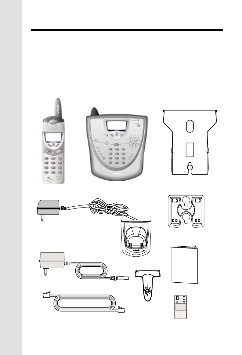
Parts Check List
1. Base Unit
2. Handset
3. Charger AC Power Adapter
4. Charger
5. Base AC Power ADapter
7. Belt clip
8. Base Wall Mounting Bracket
9. Charger Wall Mounting Bracket
10. Owner's Manual
11. Battery Pack
6. Telephone Cord
To purchase replacement battery packs, call VTech Communications Inc.
at 1-800-595-9511. In Canada, call VTech Electronics Ltd. at 1-800-267-7377.
Handset
Base Unit
Base Wall Mounting
Bracket
Chargser AC Power Adapter
Base AC Power Adapter
Telephone Line Cord
Chargser
4
Belt Clip
Charger Wall
Mounting Bracket
O
W
NER
S M
AN
U
AL
Owners Manual
Battery Pack
Page 5
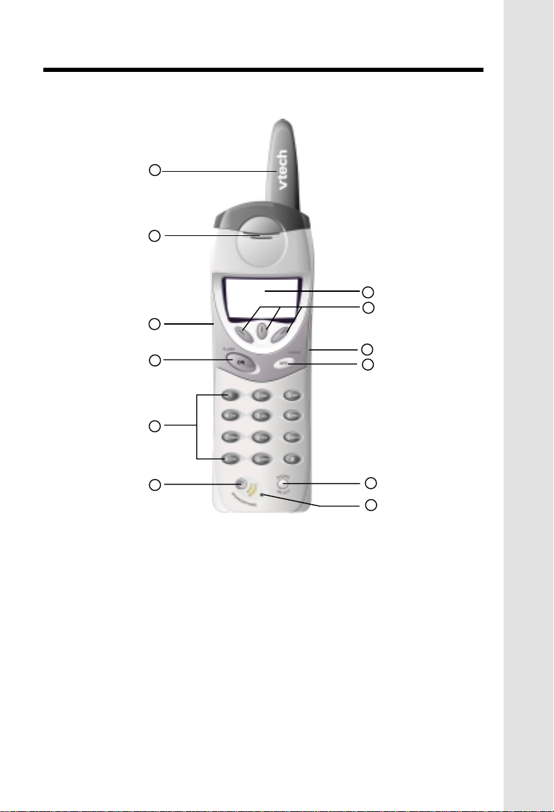
The Handset Layout
1
2
7
8
3
4
5
6
1. Antenna
2. Earpiece
3. Headset Jack (2.5mm)
4. On (Flash)
5. Dialing Key(0-9)
6. Speaker Phone
9
10
11
12
7. LCD Display
8. Soft keys
9. Volume key
10. Off (Clear)
11. Sound Select key
12. Microphone
5
Page 6
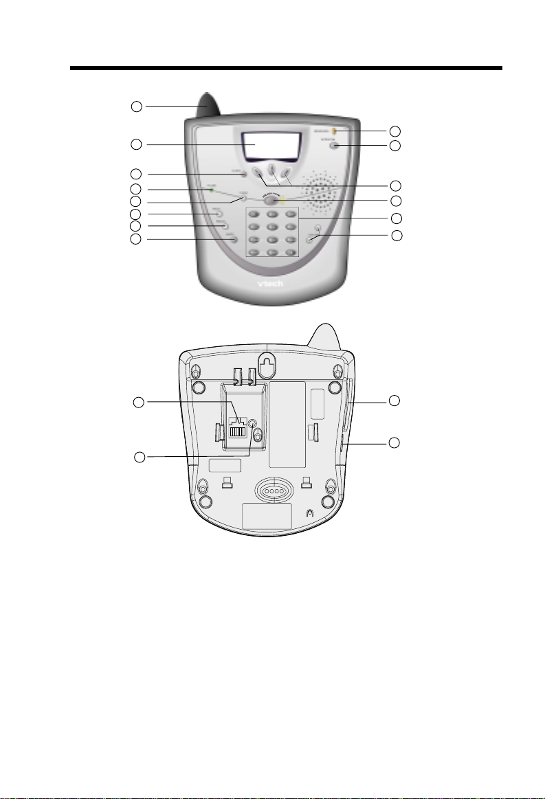
The Base Unit Layout
1
2
3
4
5
6
7
8
15
16
9
10
11
12
13
14
17
18
1. Antenna
2. LCD Display
3. Clear
4. In use
5. Flash
6. Hold
7. Redial
8. Mute
9. Messages
10. Intercom
11. Soft keys
12. Speaker Phone
13. Dialing Keys (0-9)
14. Volume Keys
15. Telephone Jack
16. DC Connector
17. Spare Battery drawer
18. Spare Battery Release
6
Page 7

Setup
1. Plug the AC power adapter into an electrical outlet, and the DC connector
into the back of the base unit.
To AC outlet
To telephone
socket outlet
To telephone
jack
AC adapter
Connecting to phone line
Plug one end of the telephone line cord into the jack on the back of the base
unit. Plug the other end of this cord into the wall jack.
Checking for dial tone
After the battery is charged press ON on the Handset. The Phone icon will
appear on the handset display, and you will hear dial tone. If not, see In Case
of Difficulty.
Tone/Pulse selection
See BASE SETTINGS for details.
CAUTION: Use only the Vtech power supply provided with your telephone.
IMPORTANT:
FOR MAXIMUM PERFORMANCE OF YOUR
CORDLESS TELEPHONE SYSTEM:
1. Choose a central location for your Base Unit.
2. Install your Base Unit and Extension Handsets
away from electronic equipment, such as
personal computers, television sets and
microwave ovens.
3. In locations where there are multiple cordless
telephones, separate base units as much as
possible.
4. Install your telephone equipment away from
heat sources and sunlight.
5. Avoid excessive moisture, dust or extreme
cold.
7
Getting Started
Page 8

Installation of Battery Pack in Handset
Follow the steps below:
1. Remove the battery cover by
pressing on the indent and
sliding downward.
2. Place the new battery pack in the
Getting Started
handset with the metal contacts
aligned with the charge contacts
in the battery compartment.
3. Replace the battery cover by
sliding it upwards.
4. If the new battery pack is not
already charged, place the
handset in the base unit, or a
remote charging stand, and allow
it to charge for 12 hours. After
initial charge, a maintenance
charge of 8 hours should be
sufficient.
The original Handset that is shipped with your VT5831
system will be automatically registered to the Base. This
Handset is HANDSET 1.
As you register additional Handsets to the system, they will be assigned
extension numbers in the following order: HANDSET 2, HANDSET 3, and finally
HANDSET 4.
Whenever a Handset battery pack is installed, the Handset will automatically
begin SEARCHING FOR BASE (if previously registered), or it will prompt you
to ENTER BASE ID to register the new Handset.
8
Page 9

Spare Battery Charger/Power Backup Function
The VT5831 uses the spare battery charger in the Base Unit. To provide
operational backup in the event of a power failure with the a fully charged battery
pack in the spare battery charger, you will still be able to place a receive calls
from the handset for up to 5 hours.
The spare battery pack can also be used to replace a drained handset battery,
ensuring uninterrupted use.
NOTE :
When using the VT5831 during Power Backup mode, audio quality may be
compromised due to reduced Power availability.
1. Open the spare battery charger
by pressing the release button,
located on the left-hand side of
the Base Unit. A drawer will open
to reveal the spare battery
compartment.
2. Place a battery pack in the
drawer with the charge contacts
facing up and to the right.
3. Push the drawer closed.
The spare battery takes 24 hours to
fully charge a drained battery.
Getting Started
9
Page 10

Charging Of Handset Battery Pack
The Handset of your VT5831 cordless telephone is powered by a rechargeable
battery pack. It charges automatically whenever the Handset is in the Base Unit.
You should charge the battery pack for 12 hours when you first receive
your phone. You'll know the battery pack needs charging when:
• The low battery message is displayed :
Getting Started
• The handset seems completely
dead, the LCD is completely
clear and does not activate
when you press the keys.
IMPORTANT:
1. Do not dispose of a battery pack in a fire, the cell may explode.
2. Do not open or mutilate the battery pack. Toxic substances may be
released, causing harm to eyes or skin.
3. Exercise care in handling battery packs in order to prevent an accidental
short of the charge contacts, potentially causing the battery pack to
overheat.
4. Do not dispose of this battery pack into household garbage. Please refer
to the following information concerning proper battery recycling:
10
Page 11

Wall Mounting
The Wall Mount bracket is designed
for use on standard Wall Mount plates
only. Wall mounting is optional.
1. Line up the tabs on the wall
mount adapter with the holes on
the bottom of the base unit.
Snap the wall mount bracket
firmly in place.
2. Plug the AC adapter into an
electrical outlet, and the DC
connector to the back of the
base unit. If the handset battery
pack has not been charged
previously, place the handset in
the base unit cradle, and allow
it to charge for 12 hours.
3. Connect the telephone line cord
to the jack on the back of the
base unit, and the other end to
the wall jack.
4. Mount the base unit on the wall.
Position the base unit so the
mounting studs will fit into the
holes on the wall mount bracket.
Slide base unit down on the
mounting studs until it locks into
place.
Getting Started
11
Page 12

Registration and Operation
Registration And Operation Of The VTech VT5820 Accessory
Handset
Your VTech VT5831 system can operate up to 6 Handsets.
The VT5820 accessory Handset consists of the following:
Getting Started
Chargser AC Power Adapter
Handset
Telephone Line Cord
Belt Clip
Battery Pack
Setup Of The VT5820 Accessory
Handset
1. Plug the AC power adapter into
2. Remove the Handset battery
3. Place the new battery pack in the
4. Replace the battery cover by
5. Place the Handset in the Charge
Chargser
Charger Wall
Mounting Bracket
an electrical outlet.
cover by pressing on the indent
and sliding downward.
Handset, with the metal contacts
aligned with the charge contacts
in the battery compartment.
sliding it upward.
Cradle, and allow it to charge for
12 hours. After the initial charge,
a maintenance charge of 8 hours
should be sufficient.
12
Page 13
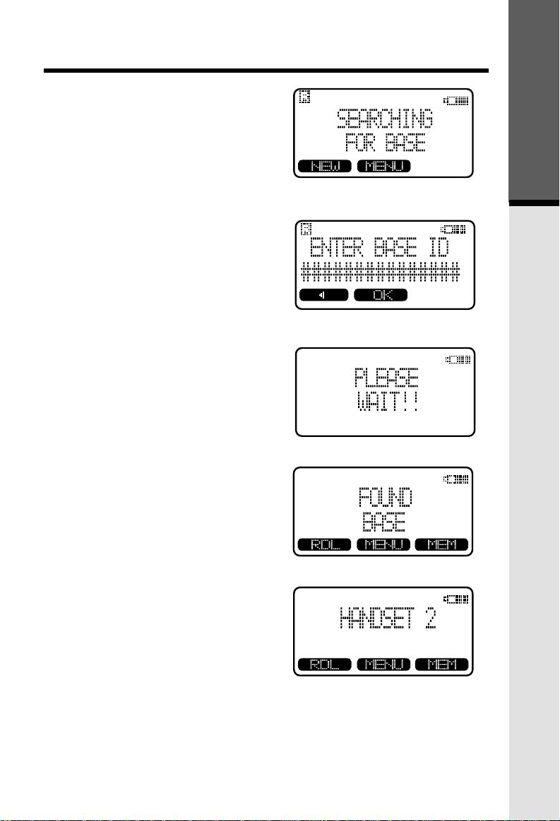
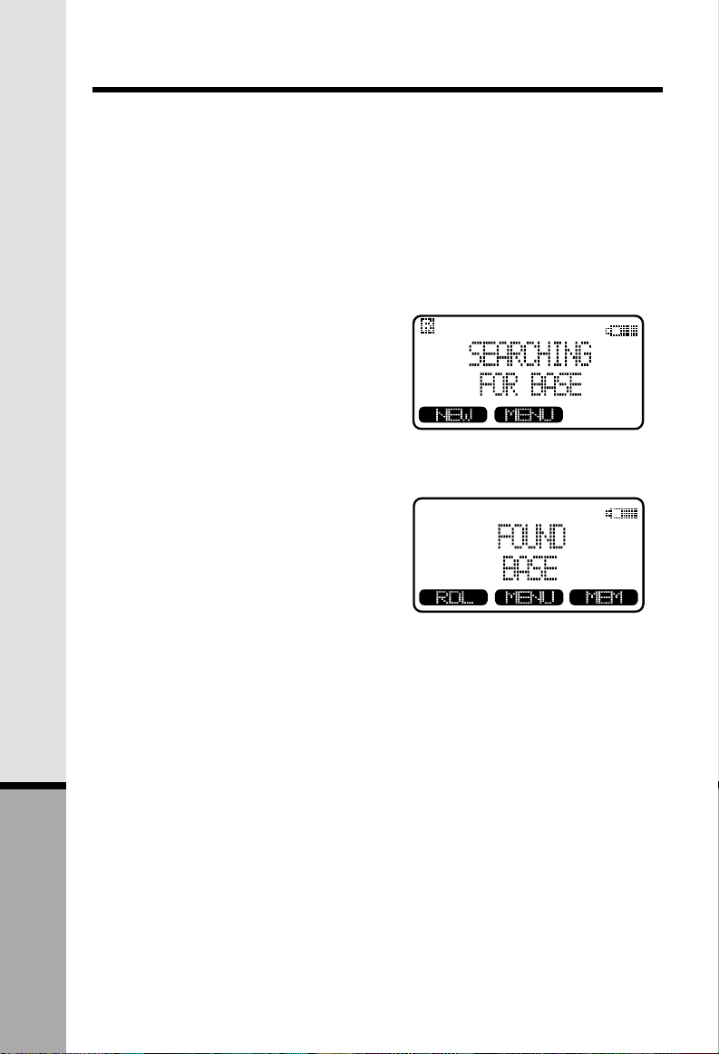
Enter Base ID Code
1. After charging the Handset,
remove it from its Charge Cradle,
the screen will display:
Registration and Operation
Getting Started
2. Press
3. Press
NEW
digit Base Unit ID code, located
on the underside of the Base
Unit.
display: PLEASE WAIT!!
, then enter the 15
OK
. The Handset will
4. Wait approximately 15 seconds.
The Handset will display:
FOUND BASE
NOTE: Occasionally, it will take
longer than 15 seconds for than
Handset to find the Base Unit.
This is normal.
If the Handset displays: BASE
BUSY TRY LATER, this
indicates that the system is in
use. Wait until the Base Unit is
in the idle (on hook) mode, and
repeat step 2 to 4.
Congratulations! You can now enjoy
the benefits of your VTECH multiHandset system.
13
Page 14
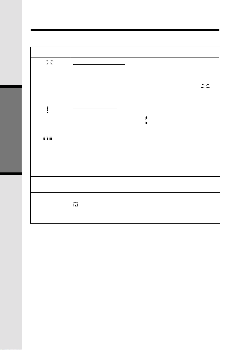
Handset Icons
Handset and Base Indicators
Icon
Basic Operation
M
H
'R'
Description
Line In Use indicator
On steady with no number next to it when a parallel set is
in use.
On steady with one or more numbers next to it, indicating
which extensions are using the line. For example,
indicates that Handset 1 and Handset 2 are on an outside
call.
Intercom indicator
On steady with the extension numbers currently on an
intercom call. For example, 02 indicates that the Base
and Handset 2 are on an intercom call.
Battery indicator
Cycles (Low, Medium, and High) when Handset battery is
charging.
Flashes when a low battery condition is detected.
Mute indicator
On steady when the Handset microphone is muted.
Hold indicator
On steady when the line is on hold.
Handset Registration indicator
is displayed when a Handset is either not registered, or
is searching for a Base unit.
12
14
Page 15
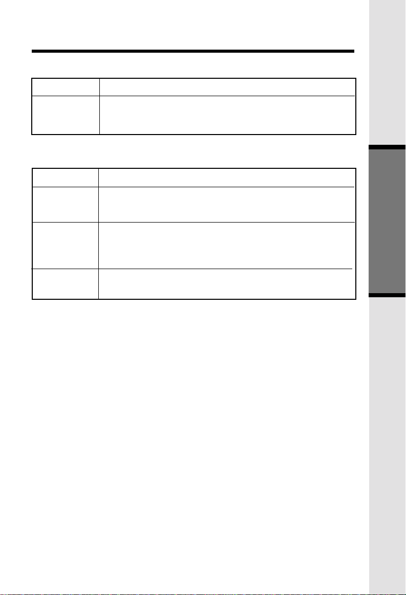
Handset LEDs
Handset and Base Indicators
LED
Message
Waiting
Base LEDS
LED
Messages
In Use
Speaker phone
Description
• Lights to indicate that you have new messages in your
voicemail. Service must be subscribed to through your local
telephone company.
Description
• Flashes to indicate that you have new messages in your
voicemail. Service must be subscribed to through your local
telephone company
• Lights when line is being used by a handset of the
GIGAPHONE system.
• Flashes when another telephone on the same line (parallel
extension) is in use.
• Flashes when HOLD function is activated.
• Lights when base speakerphone is in use.
Basic Operation
15
Page 16

Soft Menu Functions
The VT5831 has an advanced design
that uses a menu structure and soft
keys to access all of the built-in
features.
Example of the idle mode display:
RDL (Redial)
From the Handset:
Press RDL to display the last 5 telephone numbers dialed from the Handset. The
number on the top line represents the last number to be dialed.
*Use the scroll keys to highlight the desired number.
*To dial, press PHONE/FLASH or SPEAKERPHONE.
From the Base Unit:
Your VT5831 Base remembers the last 10 numbers dialed from it. Press REDIAL.
The number on the top line represents the last number to be dialed.
*Use the scroll keys to highlight the desired number.
*To dial, press SPEAKER PHONE.
Basic Operation
Erasing Numbers in Redial Memory
(Handset or Base)
* Press RDL (REDIAL at the Base), then scroll to the desired number.
* Press SELECT, then ERASE.
Saving Redial Numbers in Phone Book Memory
(Handset or Base)
* Press RDL (REDIAL at the Base), then scroll to the desired number.
* Press SELECT, then SAVE.
* You will be asked to ENTER NAME. Use the keypad to enter the desired name
(see To Store a Number/Name for more information).
* Press SAVE. The name and number has been stored in Phone Book memory.
HANDSET MENU
With the Handset in the idle (OFF) mode, press MENU to access the following options:
* CALLS LOG (Caller ID)
* INTERCOM
* HANDSET SETTINGS
* SET TIME
* CLOCK MODE
16
Page 17

Soft Menu Functions
* REGISTER
Use the scroll keys to select the desired option, then press OK.
SETTING THE TIME
* Press MENU, scroll down to SET TIME, then press OK.
* Using the keypad, enter the current time. A single-digit hour must have a zero
before it (03:56, for example)
* If you make a mistake, use < to backspace.
* Use the AM/PM key to select the correct designation.
* Press SAVE to confirm the setting.
NOTE:You can also wait for incoming Caller ID to set the clock,
rather than setting it manually.
CLOCK MODE
When your VT5831 is idle (OFF), the LCD displays the time of day, with both a digital
and analog (clock face) readout. If you do not want the time displayed, follow these
steps:
* Press MENU, scroll down to CLOCK MODE, then press OK.
* Press OFF, then press OK.
You can activate and deactivate Clock Mode as often as you wish.
Basic Operation
17
Page 18

From the Handset
From the idle (OFF) mode, press
MENU
, use the scroll keys
to select CALLS LOG, then press OK.
The Caller ID information of the most
recently received call will be displayed.
For example:
To scroll to other records, use the
aaaaaa scroll keys.
Calls Log (Caller ID)
To dial the number displayed, you can
simply press the
key.
You can also press the
access the following options ( DEL,
OPT#, SAVE):
DEL : Select this option to delete THIS or ALL records in Caller ID memory.
OPT# : Select this option to display up to four possible dialing strings of the
SAVE Select this option to save the displayed Caller ID record into Speed
From the idle (OFF) mode, press MENU. CALLS LOG will be highlighted. Press
OK, the Caller ID information from the most recently received call will be displayed.
For example:
ANDREW SMITH
555-555-555
11:15A Oct12 #01
Dialing from CID
ON
or
HANDSFREE
CID
key to
number stored in Caller ID memory. If a number is provided in the
Caller ID data, the possible options to choose from will be either 7,
8, 10, or 11 digits. For example, if the original number in Caller ID
menory was 808-880-8808, then the display options will be:
Use the UP and DOWN
keys to make selection,
and then press
or
HANDSFREE
number.
Dial Memory. Only Caller ID records with telephone numbers can
be saved into Speed Dial Memory. If you need to modify the number
after saving, see TO EDIT A NUMBER.
DIAL, ON
to dial the
18
Page 19

Calls Log (Caller ID)
To dial the number displayed, simply press SPEAKER PHONE.
To search for a different Caller ID record, use the UP and DOWN scroll keys.
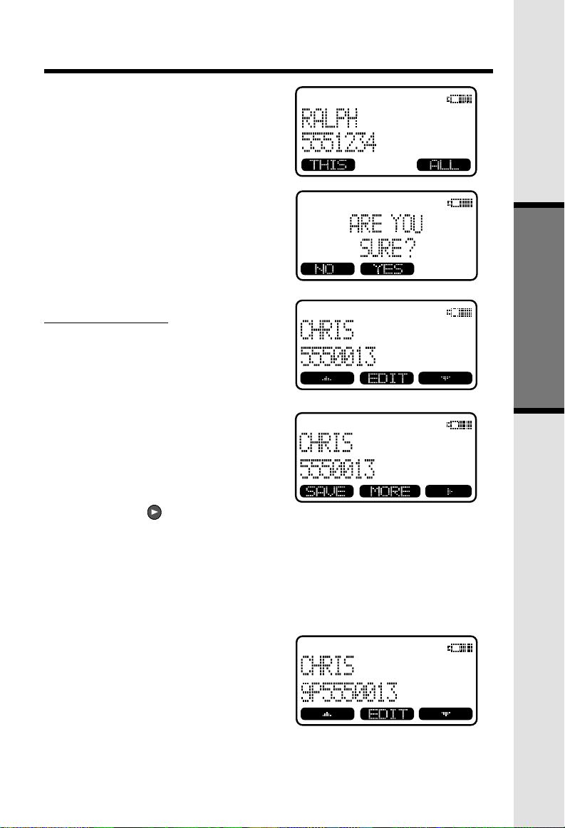
Deleting CID records
To delete the displayed Caller ID record, press CID, then DEL. You will then have
the option of deleting the single CID record (press THIS) or all stored CID records
(press ALL).
If you press ALL, the screen will ask ARE YOU SURE? Press YES to confirm the
deletion of all CID records. Or, press NO to return to the CID record previously
displayed.
NOTE: You do not have to delete Caller ID records. Your VT5831 always saves
the 50 most current CID records. As new records come in, the oldest records are
automatically deleted to make room.
Caller ID - Call Waiting ID
Your VT5831 is capable of displaying the name and/or number of the party calling
before you answer the phone (Caller ID). It is also capable of displaying Caller
ID information in conjunction with a Call Waiting alert signal (Call Waiting Caller
ID). With Call Waiting Caller ID, the Caller ID data is displayed so you can
decide whether to answer the incoming call, or continue with your current
conversation.
From the Base Unit
NOTES ABOUT CALLER ID & CALL WAITING CALLER ID
These are subscription services, provided by most regional telephone service
providers. You must subscribe to these services to get the benefits of these
features. If you do not subscribe to Caller ID services, you can still use your
VT5831 and the other features it offers.
Due to regional incompatibilities, Caller ID information may not be available
for every call you receive. In addition, the calling party may intentionally block
their name and phone number from being sent.
19
Page 20

Handset Settings
From the Handset Settings menu you can select the following options to
modify:
• RINGER VOLUME
Select this option to adjust the ringer volume. Use the scroll
keys to adjust the volume up or down. A Handset will display a graphic
indicator of the selected volume setting. Press OK to confirm your selection
and return to the Handset Settings menu.
• RINGER MELODY
Select this option to adjust the ringer melody or tone. Use the scroll
keys to select from the six available tones. Press OK to confirm your
selection and return to the Handset Settings menu.
• LOW BATT TONE
Select this option to turn the Low Battery warning tone ON or OFF. Press
the OFF or ON soft keys, to make your selection. Press OK to confirm
your selection and return to the Handset Settings menu. When set to
ON, the Handset will emit a warning tone when a Low Battery condition
Basic Operation
is detected.
• RANGE TONE
Select this option to turn the Out of Range warning tone ON or OFF. Press
the OFF or ON soft keys, to make your selection. Press OK to confirm
your selection and return to the Handset Settings menu. When set to
ON, the Handset will emit a warning tone whenever the Handset is taken
out of range of the Base.
• KEYPAD TONE
Select this option to turn the Keypad tones ON or OFF. Press the OFF
or ON soft keys, to make your selection. Press OK to confirm your selection
and return to the Handset Settings menu. When set to ON, the Handset
will emit a beep whenever a key is pressed.
• CONTRAST
Select this option to adjust the contrast level of the Handset display. Use
the scroll keys to make your selection. The handset display
will automatically adjust as you make your selection. Press OK to confirm
your selection and return to the Handset Settings menu.
LANGUAGE
•
Select this option to change the display from English to Spanish or French.
Use the scroll keys to select language, then press OK to confirm your
choice.
20
Page 21

Sound Select
SOUND SELECT
During a call, you can adjust the quality of the sound to best suit your hearing. Pressing
SOUND SELECT repeatedly will cycle you through four different frequency responses:
BASS - Low Frequency sounds enhanced
MID - Mid-Range sounds enhanced
TREBLE - High Frequency sounds enhanced
NATURAL - no frequency enhancement
The Handset will graphically display the four modes. You can also press the Left
and Right scroll keys to cycle through the four frequency choices. Press OK to confirm
your preference.
CALLS LOG
HANDSET SETTINGS
RANGE EXTENDER
REGISTER
Basic Operation
Register
Use this option to register a Handset to the VT5831 Base. You can register
a total of six Handsets to the Base. This process is activated automatically
whenever a new handset is powered up in range of the GIGAPHONE Base.
You will be prompted to enter the 15-digit Base ID code printed on the underside
of the base unit. After entering this code, press OK. The Handset will display
SEARCHING FOR BASE, and then FOUND BASE when the process is
complete.
Note : Base ID codes are 15 digits long and can include the following characters
:
0, 1, 2, 3, 4, 5, 6, 7, 8, 9, , or # .
*
21
Page 22

MEM (Memory)
The VT5831 can store up to 50 names/numbers in memory. Each memory
location can hold up to 32 digits and up to 16 characters for the name.
When prompted to ENTER NAME?, use the digit keys to 'spell' the name. Each
press of a particular key causes characters to be displayed in the following order:
Number Key
1
2
3
4
5
6
7
8
9
0
*
#
Basic Operation
Each system Handset and the Base Unit can independently. Store names and
numbers in memory.
Characters (in order)
& ' , . 1
A B C a b c 2
D E F d e f 3
G H I g h i 4
J K L j k l 5
M N O m n o 6
P Q R S p q r s 7
T U V t u v 8
W X Y Z w x y z 9
0
*
#
22
Page 23

To Store a Number/Name:
• Starting from the idle screen,
enter the number you want to
store in memory.
• Be sure to include long distance
codes and pauses (using the
PAUSE
Press the
• You will then be prompted to
ENTER NAME? Use the digit
keys to 'spell' the name. If you
make a mistake, press the
softkey. To enter a space press
aa . When finished, press
SAVE
• If there is space available in
memory, the number/name will
be saved and the Handset will
return to idle mode.
softkey) if necessary.
MEM
softkey.
.
CLR
Soft Mem Functions
Basic Operation
• If the memory is full the Handset
will display PHONEBOOK IS
FULL and exit to the idle screen
without saving the entry.
23
Page 24

To Search For and Dial a Number/
Name:
• Starting from the idle screen,
press the
memory contents.
• Using the softkeys
scroll through the memory
contents in alphabetical order.
MEM
softkey to review
Soft Mem Functions
• Or, you can press the
softkey, enter the first few
chararcters of the name and
Basic Operation
then press
you make a mistake, press
softkey. The closest match, in
alphabetical order, will be
displayed.
• Once you find the entry you
want, simply press
HANDSFREE
FIND
to search. If
to dial the number.
To Delete a Number/Name:
• Using the steps in To Search
For and Dial a Name/Number,
locate the entry you want to
delete.
• Press the
Handset will display:
EDIT
softkey. The
ON
FIND
CLR
or
24
Page 25
Soft Mem Functions
• Press the
Handset will display:
• To delete this record, press
THIS
• To confirm the deletion of
records, press
without deleting press NO.
DEL
softkey. The
.
YES
ALL
. To exit
To Edit a Number
• Using the steps in To Search
For and Dial a Name/Number,
locate the entry you want to edit.
• Press the EDIT softkey twice.
The Handset will display:
Basic Operation
• Using the softkey move
the cursor to the character you
want to edit and then enter the
corrections as needed. Press
MORE to access DEL, BACK
and PAUSE function. When
finished press the
To exit without saving press
OFF
.
• When finished the handset will
display the edited entry.
SAVE
softkey.
25
Page 26

Base Settings
BASE UNIT MENU
With the Base Unit in the idle (OFF) mode, press MENU to access the following
options:
* CALLS LOG
* BASE SETTINGS
Use the scroll keys to select the desired option, then press OK.
BASE SETTINGS
To access Base Settings, with the Base in the idle (OFF) mode, press MENU, scroll
down to BASE SETTINGS, then press OK. You now can access the following setting
options:
* RINGER VOLUME
* RINGER MELODY
* KEYPAD TONE
* TONE/PULSE
* CONTRAST
Basic Operation
* LANGUAGE
Press CLEAR at any time to back out of Base Settings mode.
RINGER VOLUME
To adjust the Base Unit ringer volume:
* Press MENU. Scroll down to BASE SETTINGS, then press OK. RINGER VOLUME
will be highlighted.
* Press OK. You will see a graph on the Base display indicating the relative volume
setting.
* Press < to lower the ringer volume. At the lowest setting (graph is completely
clear), the Base will not ring when a call comes in.
* Press > to raise the volume. At the loudest setting, the graph is completely shaded
in.
* Press OK to confirm your setting.
RINGER MELODY
There are six Base ringer melody choices. To change the melody:
* Press MENU. Scroll down to BASE SETTINGS, then press OK. Scroll down to
RINGER MELODY.
* Press OK. Use the either scroll key to sample the melodies.
* Press OK to confirm your selection.
26
Page 27

KEYPAD TONE
(preset to ON)
Keypad tones are the ‘beeps’ you hear each time you press a key on the Base Unit.
To turn this feature ON or OFF:
* Press MENU. Scroll down to BASE SETTINGS, then press OK. Scroll down to
KEYPAD TONE.
* Press OK. Choose ON or OFF.
Press OK to confirm your selection.
TONE/PULSE
(preset to TONE)
Tone dialing is the preferred method in most areas. However, if you change this
setting:
* Press MENU. Scroll down to BASE SETTINGS, then press OK. Scroll down to
TONE/PULSE.
* Press OK. Choose TONE or PULSE.
* Press OK to confirm your selection.
CONTRAST
You can adjust the Base Unit LCD screen’s contrast to suit your eyes:
* Press MENU. Scroll down to BASE SETTINGS, then press OK. Scroll down to
CONTRAST.
* Press OK. Use the < and > scroll keys to raise and lower the screen’s contrast.
Press OK to confirm your selection.
LANGUAGE
(preset to ENGLISH)
Your display can be in English, Spanish or French. To adjust:
* Press MENU. Scroll down to BASE SETTINGS, then press OK. Scroll down to
LANGUAGE.
* Press OK. Scroll to the desired language.
* Press OK to confirm your selection.
Advanced Operations
27
Page 28

28
Page 29

Handset and Base Operation
Making Calls
From the Handset
PHONE
• Press
• Dial the phone number first; then
• Press
PHONE
PHONE to use the Handset
Speakerphone feature).
Dial the phone number.
press
PHONE
PHONE).
OFF
(or, SPEAKER
-OR-
(or SPEAKER
to end your call.
Answering Calls
From the Handset
PHONE
• Press any key except
softkeys.
• Press
OFF
to end your call.
OFF
or the
Making Calls
From the Base Unit
• Press
• Press
SPEAKERPHONE
the phone number.
SPEAKERPHONE
your call.
. Dial
to end
Redial from Base Unit
Answering Calls
From the Base Unit
• Press
• Press
29
SPEAKERPHONE
SPEAKERPHONE
your call.
.
to end
Page 30

Mute Function
Handset and Base Operation
During an active call pressing either the
MUTE
key on the Base (when in speakerphone mode), will disable the
microphone. Press
MUTE
key again to return to normal 2-way conversation.
Hold Function
Flash Function
HOW TO ADJUST THE HANDSET VOLUME( also applies to the Handset
Speakerphone)
The VOLUME control is on the right edge of the Handset. During a call, press the
Advanced Operations
MUTE
soft key on the Handset or the
From the Handset :
• Press the HOLD soft key to
place a call on hold. To return
to the call press the
HANDSFREE)
From the Base :
• During an active call, press the
HOLD
key to place a call on
hold. The SPEAKERPHONE
LED will flash to indicate a call
is on hold.
• To return to the call press either
HOLD
or SPEAKERPHONE.
You can use your VT5831 with services
such as Call Waiting. Simply press the
PHONE
key on the Handset or the
key on the Base (when in speakerphone
mode) to FLASH the line.
UP or DOWN key to adjust the listening
volume to a comfortable level. Press the
OK key to confirm your selection. The
procedure is the same for the Handset
earpiece and Speakerphone.
BASE SPEAKERPHONE VOLUME:
During an active call simply press the
Volume UP or DOWN keys to adjust the
speakerphone volume
key.
.
PHONE
FLASH
(or
30
Page 31

Handset and Base Operation
Page/Intercom
From Base to ALL Handsets :
• To page all Handsets from the
Base press the INTERCOM key.
Scroll to GLOBAL PAGE, then
press OK.
• Each Handset will display
GLOBAL CALL FROM BASE.
• Any Handset can then answer
the PAGE, and enter INTERCOM
mode with the Base by pressing
the
PHONE or any number
• To end an intercom call, press
OFF
on the Handset or PAGE/
From Base to a particular Handset :
• Press the Base INTERCOM key then scroll to the Handset you want to call
(e.g.HANDSET 2).
• Handset 2 can then answer the intercom call by pressing.
• To end an intercom call press OFF on the Handset or INTERCOM on the
Base.
From Handset to Base :
• * Press MENU, then scroll down to INTERCOM.
* PRESS OK. SCROLL TO BASE, THEN PRESS OK.
* T
HE BASE WILL RING, THEN AUTOMATICALLY ENTER INTERCOM MODE.
O END THE INTERCOM CALL, PRESS OFF ON THE HANDSET OR INTERCOM ON THE BASE.
* T
From Handset to Handset :
• Press the
by the number of the other Handset
you wish to call (e.g. INTERCOM 3).
• Handset 3 can then answer the
intercom call by pressing the
INTERCOM
• To end the intercom call press
on either Handset.
Global Page from Handset
• * Press MENU, then scroll down to INTERCOM.
* Press OK. Scroll to GLOBAL PAGE, then press OK.
* Any registered Handset or Base can answer the global page, thus entering Intercom
mode.
* To end the intercom call, press OFF on the Handset or INTERCOM on the
INTERCOM
Base.
INTERCOM
key.
on Base.
key followed
OFF
INTERCOM on the Base.
key.
Advanced Operations
31
Page 32

Handset and Base Operation
Handsfree Speakerphone Operation
Your VT5831 handset has a built-in handsfree speakerphone. This feature allows
you to stand the Handset upright on a table or desktop and have handsfree
conversations. For more information, refer to MAKING CALLS in HANDSET
AND BASE OPERATION.
Base Speakerphone Operation
The Base of your VT5831 is equipped with a full duplex speakerphone. This
is a very useful feature for handsfree conversations or conference calls at the
base unit. For more information, refer to MAKING CALLS in HANDSET AND
BASE OPERATION.
Line in Use Indication
On the Handset :
When the telephone line is currently
being used by a VT5831 Handset or
the GIGAPHONE Base, a status
message similar to this will display on
idle Handset(s):
When the telephone line is currently
being used by a parallel set (a
telephone device other than the
VT5831 on the same line); the phone
icon will remain on steadily, and
EXTENSION IN USE will be displayed.
On the Base :
When a VT5831 Handset. Base is
currently being used, the LINE IN USE
LED on the base will illuminate steadily.
When a parallel set is currently being
used, the LINE IN USE LED on the
base will flash.
Advanced Operations
Low Battery Indication
When a low battery is detected, the Battery icon will flash and a warning
beep is played. The status message LOW BATTERY will also be displayed
when the Handset is in idle mode. To prevent an unexpected call drop,
a drained Handset battery should be replaced by a fully charged spare
battery.
32
Page 33

Handset and Base Operation
Message Waiting Indication
The VT5831 is compatible with optional voicemail service provided by some
local telephone companies. If you subscribe to this service, and you have new,
unplayed messages in your voicemail, a Visual Message Waiting Indicator
(VMWI) signal is transmitted by your local telephone company.
The VT5831 will detect a VMWI signal and activate a the Message Waiting light
on the Base and the Message Waiting light on the Handset. In addition, message
waiting will appear on the H0andset and Base displays.
After you check your messages, the Message Waiting indicators will
automatically turn off.
Please note that whenver new, unplayed messages are stored in your voicemail,
the local Telephone Company will continue to send a VMWI signal.
Conference Calling
The VT5831 is capable of supporting conference calls with up to two registered
Handsets, and the Base unit.
To enter a conference call, simply access the line with two or more extensions
by pressing ON (or HANDSFREE) on the Handset or SPEAKERPHONE on the
Base.
The phone icon and two or more extension numbers will be displayed
in the upper left corner of the Handset.
Transferring Calls
You can transfer calls on the VT5831 system from the Base to Handset, Handset
to Handset, or Handset to Base.
Blind Transfer
You can directly transfer any active call to another VT5831 extension without
notification by doing the following steps:
• From the Handset
* Press XFER. Scroll to the desired destination, then press OK.
* The ringing Handset or Base can pick up the transferred call just like any incoming
call.
From the Base
* Press INTERCOM. Scroll to the desired destination, then press OK.
* The ringing Handset can pick up the transferred call just like any incoming call.
33
Advanced Operations
Page 34

Handset and Base Operation
Announced Transfer:
You can perform an announced transfer (call and advise another extension)
of an active call by doing the following steps:
• the Handset
* Press HOLD to place your call on hold.
* Press MENU. Scroll to INTERCOM, then press OK.
* Scroll to the desired destination, then press OK.
* When the ringing Handset or Base answers, announce that there’s an active call
on hold.
* Press OFF (on the Handset) or INTERCOM (on the Base)
* Press PHONE (on the ‘destination’ Handset or SPEAKER PHONE (on the Base)
to pick up the call on hold.
Advanced Operations
34
Page 35

Headset Operation
Your VT5831 cordless telephone is equipped with a 2.5mm Headset Jack for
use with an optional accessory Headset for hands-free operation. If you choose
to use the Headset option, you must obtain an optional accessory Headset, which
is compatible with the VT5831.
To purchase a Headset, call VTECH Customer Service at 1-800-595-9511.
Once you have a compatible 2.5mm Headset, locate the Headset Jack on the
VT5831 Handset. Connect the plug on the Headset cord to the jack on the cordless
Handset. The plug should fit securely. Do not force the connection.
Operation
NOTE :
Whenever a compatible Headset is
connected to the cordless Handset,
the microphone on the Handset will be
muted. This is done to limit the effect
of background noise.
Many compatible Head-set have a
reversible, monaural design. You can
wear your Headset on either ear,
leaving one ear free for room
conversation.
Belt Clip
The VT5831 is also equipped with a
detachable belt clip. Align the pins on
the inside edge of the clip with the
notches on the sides of the VT5831
Handset. The belt clip should snap
securely into place. Do not force the
connection.
35
Additional Information
Page 36

Maintenance
Taking Care Of Your Telephone
Your VT5831 cordless telephone contains sophisticated electronic parts, so it
must be treated with care.
Avoid rough treatment
Place the Handset down gently. Save the original packing materials to protect
your telephone if you ever need to ship it.
Avoid water
Your telephone can be damaged if it gets wet. Do not use the Handset outdoors
in the rain, or handle it with wet hands. Do not install your Base Unit near a
sink, bathtub or shower.
Electrical storms
Electrical storms can sometimes cause power surges harmful to electronic
equipment.
For your own safety, use caution when using electric appliances during storms.
Cleaning your telephone
Your telephone has a durable plastic casing that should retain its luster for many
years. Clean it only with a soft cloth slightly dampened with water or a mild
soap. Do not use excess water or cleaning solvents of any kind.
Remember that electrical appliances can cause serious injury if used when
you are wet or standing in water. If your Base Unit should fall into water,
DO NOT RETRIEVE IT UNTIL YOU UNPLUG THE POWER CORD AND
TELEPHONE LINE CORDS FROM THE WALL. Then pull the unit out by
the unplugged cords.
Additional Information
36
Page 37

In Case Of Difficulty
If you have difficulty operating your phone, the suggestions below should solve
the problem. If you still have difficulty after trying these suggestions, call
VTECH Communications at 1-800-595-9511. In Canada, call VTECH
Electronics at 1-800-267-7377.
The Phone Doesn't Work At All
• Make sure the Power Cord is plugged in.
• Make sure the telephone line cord is plugged firmly into the Base Unit
and the telephone wall jack.
• Make sure the batteries are properly charged. If the 'LOW BATTERY'
message is shown, the battery pack needs charging.
No Dial Tone
• First check all the suggestions above.
• If you still don't hear a dial tone, disconnect the Base Unit from the telephone
jack and connect a different phone. If there is no dial tone on that phone
either, the problem is in your wiring or local service. Contact your local
telephone company.
You Get Noise, Static, Or A Weak Signal Even When You're Near
The Base Unit
• Household appliances plugged into the same circuit as the Base Unit can
sometimes cause interference. Try moving the appliance or the Base Unit
to another outlet.
You Get Noise, Static, Or A Weak Signal When You're Away From
The Base Unit
• You may be out of range. Either move closer to the Base, or relocate the
Base Unit.
• The layout of your home may be limiting the range. Try moving the Base
Unit to another position.
The Handset Does Not Ring When You Receive A Call
• Make sure you have the Handset ringer activated. To set the ringer, see
HANDSET SETTINGS and BASE SETTINGS.
• Make sure the telephone line cord is plugged firmly into the Base Unit
and the telephone jack. Make sure the power cord is plugged in.
• You may be too far from the Base Unit.
• You may have too many extension phones on your telephone line to allow
all of them to ring. Try unplugging some of the other phones.
37
Additional Information
Page 38
In Case Of Difficulty
You Hear Other Calls While Using Your Phone
• Disconnect your Base Unit from the telephone jack, and plug in a regular
telephone. If you still hear other calls, the problem is probably in your
wiring or local service. Call your local telephone company.
You Hear Noise In The Handset, And None Of The Keys Or Buttons
Work
• Make sure the power cord is plugged in.
Common Cure For Electronic
Equipment
If the unit does not seem to be
responding normally, then try putting
the Handset in the cradle. If it does not
seem to respond, do the following (in
the order listed) :
1. Disconnect the power to the
Base.
2. Disconnect the Handset battery,
and spare battery pack, if
applicable.
3. Wait a few minutes.
4. Connect power to the Base.
5. Re-install the battery pack (s)
6. Watch for Handset to display :
then
Additional Information
38
Page 39

Warranty Statement
What does this limited warranty cover?
. The manufacturer of this VTECH product, VTECH Communications, wattants
to the holder of a valid proof of purchase ("Consumer" of "you") that the product
and all accessories provided by VTECH in the sales package ("Product") are
free from material defects in material and workmanship, pursuant to the following
terms and conditions, when installed and used normally and in accordance with
operation instructions, when installed warranty extends only to the Consumer
for Products purchased and used in the United States of Ameria.
What will VTECH Communications do if the Product is not free from material
defects in materials and workmanship during the limited warranty period
("Materially Defective Product")?
. During the limited warranty period. VTECH's autorized service representative
will repair ot replace at VTECH's option, without charge, a Materially Defective
Product. If we repair this product, we may use new or refurbished replacement
parts. If we choose to replace this product, we may replace it with a new or
refurbished product of the same or similar design. VTECH will return repaired
or replacement products to you in working condition. VTECH will retain defective
parts, modules, or equipment. Repait or replacement of Product, at VTECH's
option, is your exclusive remedy. You should expect the repair or replacement
to take approximatelu 30 days.
How long is the limited warranty period?
. The limited warranty period for the product extends for ONE(1) YEAR from
the date of purchase if we repair or replace a Materially Defective Product under
the terms of this limited wattanty. This limited warranty also applies to repaired
or replacement Products for a period of either (a) 90 days from the date the
repaired or replacement Product is shipped to you or (b) the time remaining
on the original one-year wattanty; whichever is longer.
What is not covered by this limited warranty?
This limited warramty does not cover
1. Product that has been subjected to misuse, accident, shipping or other physical
damage, improper installation, abnormal operation or handling, neglect,
inundation, fire, water or other liquid intrusion; or
2. Product that has been damaged due to repair, alteration or modification
by anyone other than an authorized service representative of VTECH; or
3. Product to the extent that the problem experienced is caused by signal
conditions, network reliability or cable or antenna systems; or
4. Product to the extent that the problem is caused by use with non-VTECH
electrical accessories; or
5. Product whose warraty/quality stickers, Product serial numbers plates or
electronic serial numbers have been removed, altered or rendered illegible; or
39
Additional Information
Page 40

Warranty Statement
6. Product purchased, used, serviced, or shipped for repair from outside the
united States, or used for commercial or institutional purposes (including but
not limited to Products used for rental purposes); or
7. Product returned without vallid proof of purchase (see 2 below); or
8. Charges for installation or set up, adjustment of customer controls, and
installation or repair of systems outside the unit.
How do you get warranty service?
. To obtain warranty serivice in the United States of America, call 1 800-595-
9511 for instructions regarding where to return the Product. Before calling for
service, please check the user's manual. A check of the Product controls and
features may save you a service call.
. Except as provided by applocable law, you assum the risk of loss or damage
during transit and transportation and are responsible for delivery or handling
charges incurred in the transport of Product(S) to the service location. VTECH
will return repaired or replaced product under this limited warranty to you,
transportation, delivery or handling charges prepaid. VTECH assumes no risk
for damage or loss of the Product in transit.
. If the Product failure is not covered by this limited warranty, or proof of purchase
does not meet the terms of this limited warranty, VTECH will notify you and
will request that you authorize the cost of repair and return shipping costs for
the repair of Products that are not covered by this limited warranty.
What must you return with the Product to get warranty service?
1. Return the entire original package and contents including the Product to the
VTECH service location along with a description of the malfunction or difficulty;
2. Include "valid proof of purchase" (sales receipt) identifying the Product
purchased (Product model) and the date of purchase or receipt; and
3. Provide your name, complete and correct mailing address, and telephone
number.
Other Limitations
. This warranty is the complete and exclusive agreement between you and
VTECH. It supersedes all other written or oral communications related to this
Product. VTECH provides no other wattanties for this product. The warranty
exclusively describes all of VTECH's responsibilities regarding the product.
There are no other express warranties. No one is authorized to make
modifications to this limited warranty and you should not rely on any such
modification.
Additional Information
40
Page 41

Warranty Statement
State Law Rights: This warranty gives you specific legal rights, and you may
also have other rights which vary from state to state.
Limitations: Implied warranties, including those of fitness for a particular purpose
and merchantability (an unwritten warranty that the product is fit for ordinary
use) are limited to one year from date of purchase. Some states do not allow
limitations on how long an implied warranty lasts, so the above limitation may
not apply to you.
In to event shall VTECH be liable for any indirect, special, incidental,
consequential, or similar damages(including, but not limited to lost profits or
revenue, inability to use the product, or other associated equipment, the cost
of substitute equipment, and claims by third parties) resulting from the use of
this product, some states do not allow the exclusion or limitation of incidental
or consequential damages, so the above limitation or exclusion may not apply
to you.
41
Additional Information
Page 42

42
Page 43

FCC and IC Regulations
This equipment complies with Parts 15 of the Federal Communications
Commission (FCC) rules for the United States. It also complies with regulations
RSS210 and CS-03 of Industry and Science Canada. Operation is subject to
the following two conditions: (1) this device may not cause interference, and
(2) this device must accept any interference, including interference that may cause
undesired operation of the device.
A label is located on the underside of the Base Unit containing either the FCC
registration number and Ringer Equivalence Number (REN) or the IC registration
number and Load Number. You must, upon request, provide this information
to your local telephone company.
This equipment is compatible with inductively coupled hearing aids.
Should you experience trouble with this telephone equipment, please contact:
VTech Communications Inc
CUSTOMER SERVICE. at 1-800-595-9511. In Canada, call VTECH Electronics
at 1-800-267-7377.
For repair/warranty information. The telephone company may ask you to
disconnect this equipment from the line network until the problem has been
corrected.
FCC Part 15
Warning: Changes or modifications to this unit not expressly approved by the
party responsible for compliance could void the user's authority to operate the
equipment.
The equipment has been tested and found to comply with part 15 of the FCC
rules. These limits are designed to provide reasonable protection against harmful
interference in a residential installation. This equipment generates, uses and
can radiate radio frequency energy and, if not installed and used in accordance
with the instructions, may cause harmful interference to radio communications.
However, there is no guarantee that interference will not occur in a particular
installation. If this equipment does cause harmful interference to radio or television
reception, which can be determined by turning the equipment off and on, the
user is encouraged to try and correct the interference by one or more of the
following measures:
- Reorient or relocate the receiving antenna.
- Increase the separation between the equipment and receiver.
- Connect the equipment into an outlet or on a circuit different from that to
which the receiver is connected.
- Consult the dealer or an experienced radio/TV technician for help.
43
Page 44

FCC and ACTA Regulations
FCC Part 68
If this equipment was approved for connection to the telephone network prior to July
23, 2001, it complies with Part 68 of the Federal Commission (FCC). If the equipment
was approved after that date, it complies with the Part 68 rules and with Technical
Requirements for Connection of Equipment to the Telephone Network adopted by the
Administrative Council for Terminal Attachments (ACTA). We are required to provide
you with the following information.
1. Product identifier and REN information
The label on the back or bottom of this equipment contains, among other things,
an identifier indicating product approval and the Ringer Equivalence Number (REN).
This information must be provide to your local telephone company upon request.
For equipment approved prior to July 23, 2001, the product identifier is preceded
by the phrase "FCC Reg NO." and the REN is listed separately. For equipment
approved after that date, the product identifier is preceded by "US" and a colon
(:), and the REN is encoded in the product identifier without a decimal point as
the sixth and seventh characters following the colon. For example, the product
identifier US: AAAEQ03T123XYZ would indicate an REN of 0.3.
The REN is used to determine how many devices you may connect to your telephone
line and still have them ring when you are called. In most, but not all areas, the
sum of all RENs should be five (5.0) or less. You may want to contact your local
telephone company for more information.
2. Connection and use with the nationwide telephone network
The plug and jack used to connect this equipment to the premises wiring and the
telephone network must comply with the applicable Part 68 rules and technical
requirements adopted by ACTA. A compliant telephone cord and modular plug is
provided with this product. It is designed to be commected modular jack that is
also compliant. An RJ11 jack should normally be used for connecting to a single
line and an RJ14 jack for two lines. See Installation Instructions in the user's manual.
This equipment connected to your telephone line, ensure the connection of this
equipment does not disable your alarm equipment. If you have questions about
what will disabel alarm equipment, consult your telephone company or a qualified
installer.
3. Repair instructions
If this equipment is malfunctioning, it must be unplugged from the modular jack
until the problem has been corrected. Repairs to this telephone equipment can
only be made by the manufacturer or its authorized agents. For repair procedures,
following the instructions outlined under the Limited Warrantly.
4. Rights of the telephone company
If this equipment is causing harm to the telephone network, the telephone company
may temporarily discontinue your telephone service. The telephone company is
required to notify you before interrupting service. If advance notice is not practical,
you will be notified as soon as possible. You will be given the opportunity to correct
the problem and the telephone company is required to inform you of your right
to file a complaint with the FCC. Your telephone company may make changes
in its facilities, equipment, operation, or procedures that could affect the proper
functioning of this product. The telephone company is required to notify you if such
changes are planned.
Additional Information
44
Page 45

FCC and ACTA Regulations
5. Hearing aid compatibility
If this product is equipped with a corded or cordless handset, it is hearing aid
compatible.
6. Programming/testing of emergency numbers
If this product has memory dialing locations, you may choose to store police, fire
department and emergency medical service telephone numbers in these locations.
If you do, please keep three things in mind:
a We recommend that you also write the telephone number on the directory card,
so that you can still dial the emergency number manually if the memory dialing
ferture doesn't work.
b This ferture is provided only as a conbenience, and the manufacturer assumes
no responsibility for customer reliance upon the memory ferature.
c Testing the emergency telephone numbers you have stored is not recommended.
However, if you do make a call to an emergency number:
• You must remain on the line and briefly explain the reason for the call
before hanging up.
• Programming/testing of emergency numbers should be performed during
off-peak hours, such as in the early morning or late evening, when the
emergency services tend to be less busy.
IC (Industry Canada)
This telephone is registered for use in Canada.
Notice :
The REN assigned to this device denotes the number of devices you may connect
to the telephone loop which is used by the device to prevent overloading The
termination on a loop may consist of any combination of devices subjected only
to the requirement that the sum of the REN does not exceed five (5.0)
Notice :
The Industry Canada label identifies certified equipment. This certification
means that the equipment meets certain telecommunications network protective,
operational and safety requirements. The Department does not guarantee the
equipment will operate to the user's satisfaction.
45
Additional Information
Page 46

FCC and IC Regulations
Before installing this equipment, users should ensure that it is permissible to
be connected to the facilities of the local telecommunications company. The
equipment must also be installed using an acceptable method of connection.
The customer should be aware that compliance with the above conditions may
not prevent degradation of services in some situations.
Repairs to certified equipment should be made by an authorized Canadian
maintenance facility designated by the supplier. Any repairs or alterations made
by the user to this equipment, or equipment malfunctions, may give the
telecommunications company cause to request the user to disconnect the
equipment.
Users should ensure for their own protection that the electrical ground
connections of the power utility, telephone lines and internal metallic water pipe
system, if present, are connected together. This precaution may be particularly
important in rural areas.
Caution :
Users should not attempt to make such connections themselves, but should
contact the appropriate electrical inspection authority, or electrician, as
appropriate.
Your VT 2431 is designed to operate at the maximum power allowed by the
FCC and IC. This means your Handset and Base Unit can communicate only
over a certain distance - which will depend on the location of the Base Unit
and Handset, weather, and the construction and layout of your home or office.
Additional Information
46
Page 47

Technical Specifications
FREQUENCY CONTROL
Crystal controlled
PLL synthesizer
TRANSMIT FREQUENCY
Base : 5744.736 - 5825.952 MHz
Handset:2401.056 - 2482.272 MHz
RECEIVE FREQUENCY
Base:2401.056 - 2482.272 MHz
Handset : 5744.736 - 5825.952 MHz
CHANNELS
95 Channels
NOMINAL EFFECTIVE RANGE
Maximum power allowed by FCC and
IC. Actual operating range may vary
according to environmental conditions
at the time of use.
SIZE
Handset : 193mm x 52mm x 40mm
Base : 192mm x 143mm x 91mm
WEIGHT
Handset : 138 grams
Base : 396 grams
POWER REQUIREMENTS
Handset: 1500mANiMH/ 800mA
Ni-Cd Battery Pack
Base : 7 VDC @ 900mA
MEMORY
Speed Dial: 50 Memory locations, into
32 digits per location.
CID : Alpha Numeric Display
50 Memory locations
SPECIFICATIONS ARE TYPICAL
AND MAY CHANGE WITHOUT
NOTICE.
47
Page 48

Table Of Contents
1.
Important Safety
Instructions
3. Introduction
4. Parts Check List
5. The Handset Layout
6. The Base Unit Layout
7. Getting Started
7. Setup
8. Installation of Battery Pack
9. Spare Battery Charger/
10. Charging Of Handset
11. Wall Mounting
12. Registration and Operation
in Handset
Power Backup Function
Battery Pack
14. Basic Operation
14. Handset and Base
Indicators
16. Soft Menu Functions
16. RDL (Redial)
16. MENU
17. Calls Log
(Caller ID)
18. Handset
Settings
19. Range
Extender
19. Register
20. MEM (Memory)
21. Soft Mem Functions
21.
Name
To Store a Number/
22. To Search For and
Dial
a Number/Name
22.
Name
23.
Name
24. Base Settings
To delete a Number/
To Edit a Number/
25. Advanced Operations
25.
25. Making Calls
25. Answering Calls
25. Redial from Base Unit
26. Mute Function
26. Hold Function
26. Flash Function
26. Volume Control
27. Page/Intercom
28.
28. Base Speakerphone
28. Line in Use Indication
28. Low Battery Indication
29.
29. Conference Calling
29. Transferring Calls
30. Quick Memory Keys
Handset and Base
Operation
Handsfree
Speakerphone
Operation
Operation
Message Waiting
Indication
on Base
31. Additional Information
31. Headset Operation
32. Maintenance
33. In Case Of Difficulty
35. Warranty Statement
37. FCC and IC Regulations
40. Technical Specifications
Page 49

VTECH TELECOMMUNICATIONS LTD.
A member of THE VTECH GROUP OF COMPANIES.
Distributed in the U.S.A. by VTech Communications Inc. Beaverton, Oregon, 97008
Distributed in Canada by VTech Electronics Canada Ltd. 7671 Alderbridge Way, Richmond,
B.C. V6X 1Z9.
Copyright 2002 for VTECH TELECOMMUNICATIONS LTD.
Printed in China
91-5826-10-00
ISSUE 0
 Loading...