

Page 1
TECH ENGINEERING CANADA LIMITED
V
TITLE PDL GX Internal Product Specification
MODEL PDL GX
PDL GX
Internal
Product Specification
NOT FOR EXTERNAL RELEASE
Document ID:
Note: All rights reserved. No part of this publication may be reproduced or transmitted in any form or by
any means. The only controlled copy of this document is kept in electronic form on the VTECH computer
network. All printed copies are uncontrolled documents and are not updated. This Procedure is the
property of VTECH Engineering Canada Ltd., and shall be returned upon request
.
Prepared By Gordon Ryley
Title Project Manager
Approved By
Title
GXSPC3-0.DOC
PRC #: 00DM
Reference: PRC 00DM Revision: 3.0 Page: 1 of 56
This document is proprietary to V
Specifications are preliminary and are subject to change without notice.
TECH ENGINEERING CANADA LTD
. 23624
Page 2
TECH ENGINEERING CANADA LIMITED
V
TITLE PDL GX Internal Product Specification
MODEL PDL GX
Revision History
Revision No Description Page Effective Date
Preliminary July 21,’98
1 First Release Aug 14,’98
2 Updated Release with UI changes All Sept 22, 1998
2.1 Incorporated Regulatory Requirements
and Page Key operation
2.2 Changes to Electrical Specs. Changed
title to Internal Product Spec.
Added Base LED Operation
2.3 Revised after TM1 Review Comments.
Added Call Forward Display and changes
to menu displays
2.4 Revised Call Forward operation as per
Radio Shack req’s. Corrected redial
examples. Corrected CID Recall Option
examples. Revised CLEAR MEMORY
menu operation. Defined VMWI as a
factory programmable option.
Minor corrections to other sections.
3.0 Removed OUT OF AREA message
description from CID. Corrected last
message for Step 6 on SET RING TYPE
description. Corrected Set Ring Volume
description Step 6 to say LOW instead of
HIGH.
Added CID display of telephone numbers
section.
Added Red/Green or All Red LED
Indicator Options
6,37 24-SEP-98
All 22-OCT-98
All 5-NOV-98
pp. 15, 22, 23,
25, 29, 34-38,
and 42.
All 18-JAN-99
25-NOV-98
Reference: PRC 00DM Revision: 3.0 Page: 2 of 56
This document is proprietary to V
Specifications are preliminary and are subject to change without notice.
TECH ENGINEERING CANADA LTD
. 23624
Page 3

TECH ENGINEERING CANADA LIMITED
V
TITLE PDL GX Internal Product Specification
MODEL PDL GX
Table of Contents
1. Overview....................................................................................6
1.1 General Description................................................................................... 6
1.2 Regulatory Standards................................................................................ 6
1.3 Feature List ................................................................................................ 7
1.3.1 Basic Features .....................................................................................................................7
1.3.2 Unique Features ..................................................................................................................7
1.3.3 Features Not Provided ........................................................................................................8
1.4 Cosmetic Styling........................................................................................ 9
2. Functional Description .............................................................11
2.1 Handset Display and Keypad Layout ....................................................... 11
2.2 Base Key Layout and Indicators............................................................... 12
2.3 Base LED User Interface Status Indicators............................................. 13
3. User Interface Specification.....................................................14
3.1 User Interface Status Tones ..................................................................... 14
3.2 Navigation/Features/Menus ...................................................................... 14
3.2.1 On Hook State Menus .........................................................................................................15
3.2.2 Off Hook State Menus .........................................................................................................15
3.2.3 Mode Timeout ......................................................................................................................16
3.3 Dial Modes.................................................................................................. 17
3.3.1 Pre-Seizure (On-Hook) Dialing or Pre-Dial ........................................................................17
3.3.1.1 Pre-Dial Digit Entry and Editing .....................................................................................17
3.3.1.2 Pre-Dial Example .............................................................................................................18
3.3.2 Post-Seizure Dialing (Off-Hook) or Live Dial ....................................................................19
3.4 Using SELECT or PHONE key When Recalling Numbers ...................... 19
3.4.1 Pre-Dial Recall Example Using PHONE Key (WYSIWYG) ................................................20
3.4.2 Pre-Dial Recall Using SELECT Key....................................................................................20
3.4.3 Live-Dial Recall Using PHONE or SELECT Key................................................................21
3.5 Placing A Call on Hold............................................................................... 21
3.6 Last Number Redial ................................................................................... 22
Reference: PRC 00DM Revision: 3.0 Page: 3 of 56
This document is proprietary to V
Specifications are preliminary and are subject to change without notice.
TECH ENGINEERING CANADA LTD
. 23624
Page 4

TECH ENGINEERING CANADA LIMITED
V
TITLE PDL GX Internal Product Specification
MODEL PDL GX
3.6.1 Review/Recalling Most Recently Dialed Numbers from Redial Memory .......................22
3.6.1.1 Redial Example Using PHONE key from Pre-Dial Mode: .............................................23
3.6.1.2 Redial Example Using PHONE key from Live-Dial Mode: ...........................................24
3.6.2 Storing Redial Records.......................................................................................................24
3.7 Incoming Calls ........................................................................................... 25
3.7.1 Ringing .................................................................................................................................25
3.7.2 Answering the Incoming Call .............................................................................................25
3.7.3 Terminating the Incoming Call...........................................................................................25
3.8 Calling Line ID Functions.......................................................................... 26
3.8.1 CID Type I ............................................................................................................................. 26
3.8.2 Call Forward Indicator.........................................................................................................26
3.8.3 New Calls Indicator .............................................................................................................27
3.8.3.1 New Calls LED Indicator Option.....................................................................................27
3.8.4 CID Type II ............................................................................................................................ 27
3.8.5 Review/Recall Telephone Numbers from CID Memory....................................................27
3.8.5.1 CID Number Recall Options............................................................................................29
3.8.6 Deleting a CID Record in Review Mode............................................................................. 30
3.8.7 Call Forward Display of Telephone Numbers...................................................................31
3.9 Speed Dial Functions ................................................................................ 32
3.9.1 Programming Speed Dial Memory .....................................................................................32
3.9.1.1 Program Speed Dial Example......................................................................................... 32
3.9.2 Review/Recall Telephone Number from Speed Dial Memory .........................................33
3.9.2.1 Speed Dial Review Example ........................................................................................... 34
3.9.3 Deleting a Speed Dial Location in Review Mode..............................................................35
3.10 Clearing CID, Speed Dial Memory and VMWI .......................................... 36
3.10.1 Clear Memory Menu Structure If VMWI Is Supported ......................................................36
3.10.2 Clear Memory Menu Structure If VMWI Is NOT Supported .............................................36
3.10.3 Clearing The Visual Message Waiting Indicator (If VMWI Option is Supported) ..........37
3.10.4 Clearing All CID Records ....................................................................................................38
3.10.5 Clearing All Speed Dial Locations .....................................................................................39
3.11 Flashing the Line/Switching Over to New Call........................................ 40
3.12 Visual Message Waiting Indication (VMWI)............................................. 40
3.12.1 VMWI LED Display Option ..................................................................................................40
3.13 Setup Mode Options.................................................................................. 41
3.13.1 Ring Type Setting (4 selection and OFF) ..........................................................................42
3.13.2 Ringer Volume Control (High or Low) ............................................................................... 43
3.13.3 Dialing Type Selection (Tone or Pulse) .............................................................................44
3.13.4 Keyclick Selection (On or Off)............................................................................................45
3.14 Page Key Operation................................................................................... 46
3.15 In Use/Charging LED Indicator ................................................................. 46
3.15.1 Red/Green LED Option........................................................................................................46
Reference: PRC 00DM Revision: 3.0 Page: 4 of 56
This document is proprietary to V
Specifications are preliminary and are subject to change without notice.
TECH ENGINEERING CANADA LTD
. 23624
Page 5

TECH ENGINEERING CANADA LIMITED
V
TITLE PDL GX Internal Product Specification
MODEL PDL GX
3.15.1.1 In Use/Charging LED Display State Priority (Red/Green LEDs)................................ 46
3.15.2 All Red LED Option..............................................................................................................46
3.15.2.1 In Use/Charging LED Display State Priority (All Red LEDs)......................................47
3.16 Temporary Tone Activation....................................................................... 47
3.17 Ear Piece Volume Adjustment .................................................................. 47
3.18 Spare Battery/POTS mode ........................................................................ 48
3.19 Low Battery Warning................................................................................. 48
3.20 Parallel Set Indication ............................................................................... 48
3.21 Headset Jack.............................................................................................. 49
3.22 No Telephone Line Connected ................................................................. 49
3.23 Display Priority of Non Mode Specific Messages ................................... 50
3.24 Channel Search/Out of Range Indication ................................................ 51
4. Electrical Specifications...........................................................52
4.1 Operating Conditions ................................................................................ 52
4.2 DC Electrical Characteristics.................................................................... 52
4.3 Audio Specification ................................................................................... 53
4.4 Telephone Line Interface Specification ................................................... 54
4.5 Calling Line Identification Specification.................................................. 55
4.6 Radio Specification ................................................................................... 56
4.6.1 Frequency Allocation ..........................................................................................................56
4.6.2 Base Unit Frequencies........................................................................................................56
4.6.3 Handset Unit Frequencies ..................................................................................................56
Reference: PRC 00DM Revision: 3.0 Page: 5 of 56
This document is proprietary to V
Specifications are preliminary and are subject to change without notice.
TECH ENGINEERING CANADA LTD
. 23624
Page 6

TECH ENGINEERING CANADA LIMITED
V
TITLE PDL GX Internal Product Specification
MODEL PDL GX
1. Overview
1.1 General Description
The PDL GX is a 900 MHz digital cordless telephone in a form factor which half the size of the existing
VTECH digital product. This is a higher end product by virtue of the level of integration required in order to
meet the form factor requirements. This is also a full featured phone which is menu driven with a 2x12
alphanumeric display capable of receiving Caller ID type I and type II.
1.2 Regulatory Standards
As a requirement for sale in the United States, the product will comply with the electrical specifications
defined in the following documents:
•
FCC Part 15 Radio Emissions Requirements
•
FCC Part 68 Telephone Line Interface Requirements
•
UL 1459 Safety Requirements
As a requirement for sale in Canada, the
the following documents:
•
IC RSS-210 Radio Emissions Requirements
•
IC CS-03 Telephone Line Interface Requirements
•
CSA 225 Safety Requirements
In addition to the above mandatory regulations, the recommendations provided in EIA-470-B, TIA 571,
TIA631and IEC801-2 will be used as a guideline.
The caller ID display module meets protocol requirements specified in the following standards documents:
Bellcore TR-NWT-001401 Issue 1
“ Visual Message Waiting Indicator”
Bellcore TR-NWT-000030 Issue 2
"Voiceband Data Transmission Interface Generic Requirements"
Bellcore TR-NWT-000031 Issue 4
"CLASS Feature: Calling Number Delivery"
Bellcore TR-NWT-001188 Issue 1
"CLASS Feature: Calling Name Delivery Generic Requirements"
product
will comply with the electrical specifications defined in
Reference: PRC 00DM Revision: 3.0 Page: 6 of 56
This document is proprietary to V
Specifications are preliminary and are subject to change without notice.
TECH ENGINEERING CANADA LTD
. 23624
Page 7

TECH ENGINEERING CANADA LIMITED
V
TITLE PDL GX Internal Product Specification
MODEL PDL GX
1.3 Feature List
1.3.1 Basic Features
•
Name / number caller ID display with 50 call storage capacity
•
32kbps ADPCM voice coding
•
2 row by 12 character 5x7 dot matrix alpha-numeric LCD display on handset
•
10 channel operation with auto channel selection
•
900 MHz Operation
•
24 bit digital security code for 16.8 million combinations
•
DTMF and Pulse dialing
•
20 number/location programmable memory for up to 20 digit phone number
•
Automatic search for best available channel
•
Low battery detect and warning indicator
•
Handset power saving 7 days (less during out-of-range)
•
7.0 Hours continuous talk time
•
Volume adjust on handset
•
Hearing-aid compatible receiver
•
Provisions for spare handset battery pack in the base unit
•
Complete battery back-up in case of power failure
•
Backlit LCD on the handset
•
Auto hang-up when returning the handset to the base cradle.
•
Detachable power supply
•
Support for headsets with 2.5mm jacks.
1
1
1
Note that this is only when masked ROM is used. Use of external ROM will diminish the talk/standby
time.
1.3.2 Unique Features
•
Use of E
•
Use of E
dial numbers
•
Handset allows for on-the-fly battery replacement
•
Fully digital link between handset and base
•
Digitally-scrambled voice communication between handset and base has extremely high immunity to
noise and interfering signals
•
Out-of-range indication while the handset is in use and in standby mode
•
Removable battery pack
•
Easy answer - When the phone rings simply press any key (except OFF) on the handset to answer
when in idle mode.
•
A faster charge (.2C) capability will be provided on the base for the handset battery. The unit will
automatically switch over to regular trickle charge (.1C) when required.
•
The electrical design will support charging in the face up position.
•
Ringer muting
2
PROM in base unit for permanent memory storage of security code
2
PROM in the handset for nonvolatile storage of the security code, CID messages and speed
Reference: PRC 00DM Revision: 3.0 Page: 7 of 56
This document is proprietary to V
Specifications are preliminary and are subject to change without notice.
TECH ENGINEERING CANADA LTD
. 23624
Page 8

TECH ENGINEERING CANADA LIMITED
V
TITLE PDL GX Internal Product Specification
MODEL PDL GX
1.3.3 Features Not Provided
•
The privacy feature is not provided
•
Stutter dial tone detection
•
Automatic line drop is not provided
•
Name dialing is not provided
•
Multi handset capability is not provided.
•
There is no Page LED on the base
•
No other modes of operation available while on HOLD
•
Manual channel change has been deleted as the auto channel change algorithm takes care of this
function.
•
Automatic security code updating when the handset is cradled has been eliminated. The base and
handset security codes are now factory preset and stored in E
security codes are therefore not generated every time the unit is re-cradled.
2
PROM for the life of the unit. New
Reference: PRC 00DM Revision: 3.0 Page: 8 of 56
This document is proprietary to V
Specifications are preliminary and are subject to change without notice.
TECH ENGINEERING CANADA LTD
. 23624
Page 9
TECH ENGINEERING CANADA LIMITED
V
TITLE PDL GX Internal Product Specification
MODEL PDL GX
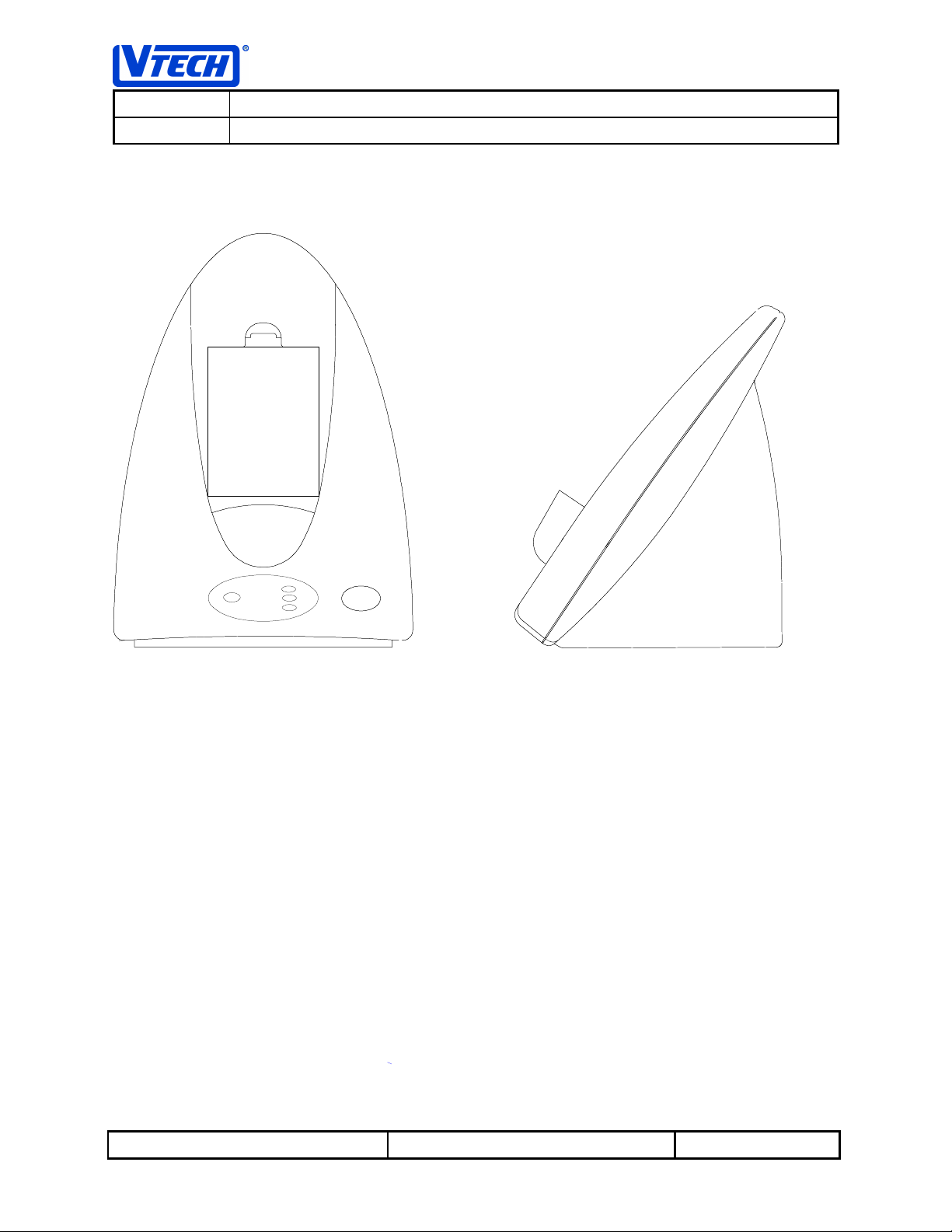
1.4 Cosmetic Styling
Base Unit
Reference: PRC 00DM Revision: 3.0 Page: 9 of 56
This document is proprietary to V
Specifications are preliminary and are subject to change without notice.
TECH ENGINEERING CANADA LTD
. 23624
Page 10
TECH ENGINEERING CANADA LIMITED
V
TITLE PDL GX Internal Product Specification
MODEL PDL GX
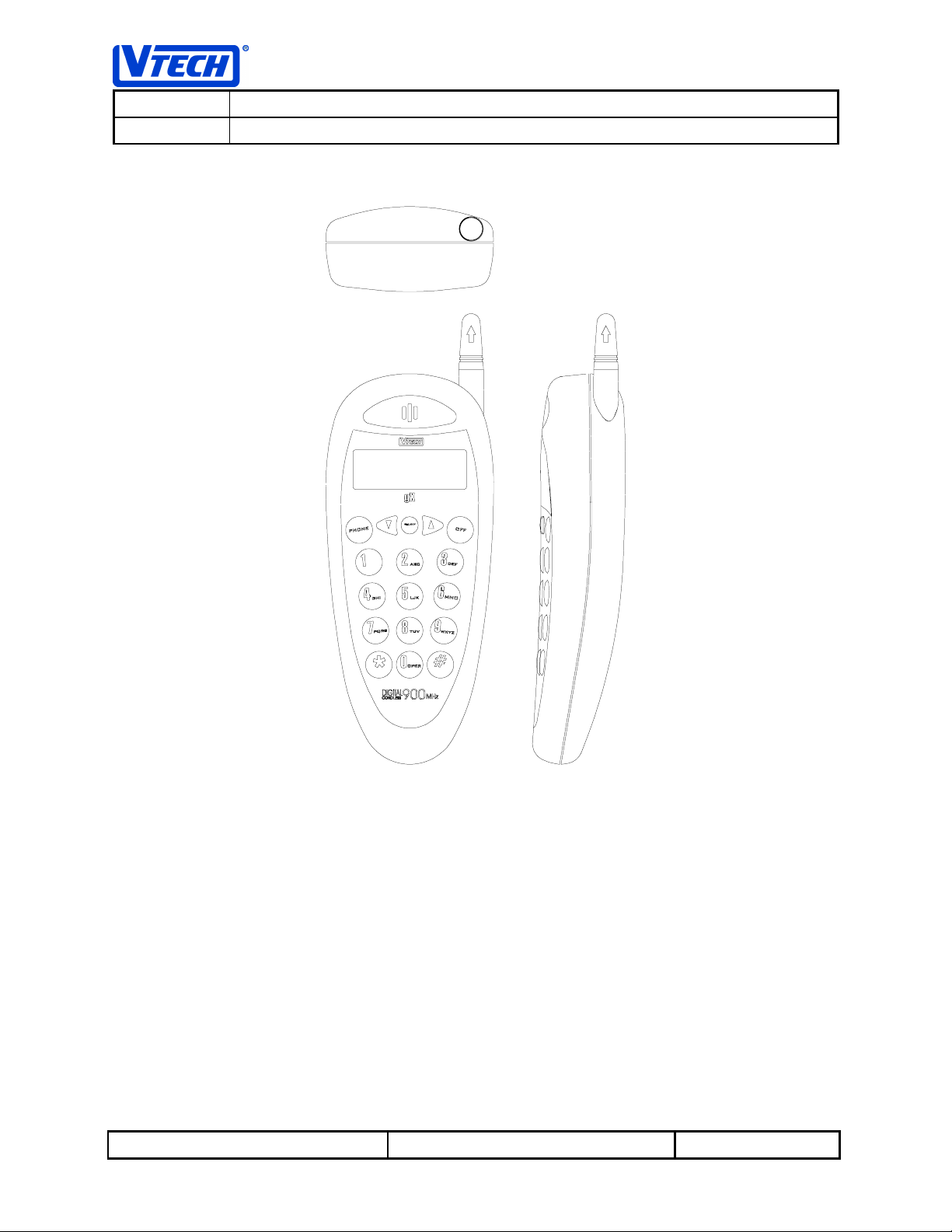
Handset Unit
Reference: PRC 00DM Revision: 3.0 Page: 10 of 56
This document is proprietary to V
Specifications are preliminary and are subject to change without notice.
TECH ENGINEERING CANADA LTD
. 23624
Page 11
TECH ENGINEERING CANADA LIMITED
V
TITLE PDL GX Internal Product Specification
MODEL PDL GX
2. Functional Description
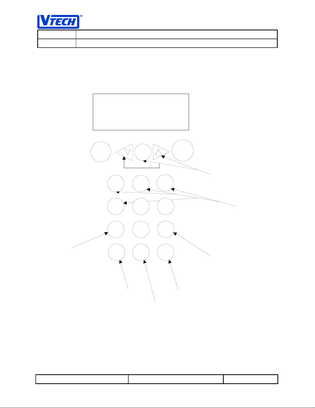
2.1 Handset Display and Keypad Layout
2 X12 LCD DISPLAY
PRESS AND
HOLD TO VIEW
CID TIME & DATE
PHONE
1 2
GHI
4
PQRS
7
*
TEMP.
TONE ACTIVATION
SELECT
ABC
IJK
5
TUV
8
OPER
0
OFF
DEF
3
MNO
6
WXYZ
9
#
HOLD
TO DELETE
CID & SPEED DIAL
LOCATION
HOLD TO ENTER
PAUSE DIGIT IN
PRE-DIAL
MENU NAVIGATIONAL
KEYS
PREFIX OPTIONS
PRESS AND
HOLD TO
VIEW
MORE
CID RECALL
Reference: PRC 00DM Revision: 3.0 Page: 11 of 56
This document is proprietary to V
Specifications are preliminary and are subject to change without notice.
TECH ENGINEERING CANADA LTD
. 23624
Page 12
TECH ENGINEERING CANADA LIMITED
V
TITLE PDL GX Internal Product Specification
MODEL PDL GX
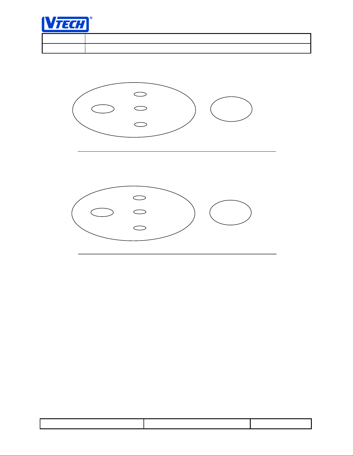
2.2 Base Key Layout and Indicators
POWER
MESSAGE WAITING
NEW CALLS
IN USE/CHARGING
SPARE BATTERY
OR
POWER
IN USE/CHARGING
SPARE BATTERY
PAGE
PAGE
Reference: PRC 00DM Revision: 3.0 Page: 12 of 56
This document is proprietary to V
Specifications are preliminary and are subject to change without notice.
TECH ENGINEERING CANADA LTD
. 23624
Page 13

TECH ENGINEERING CANADA LIMITED
V
TITLE PDL GX Internal Product Specification
MODEL PDL GX
2.3 Base LED User Interface Status Indicators
The following status is indicated on the base unit LED display:
Status Type Description
POWER
IN USE (off hook)
RINGING
CALL HOLD
CHARGING
ON-HOOK & NO
HANDSET IN CRADLE
SPARE BATTERY
MESSAGE WAITING
NEW CALLS
POTS MODE
When the POW ER LED is lit solid RED, it indicates that power to the base
unit is on.
When the IN USE/CHARGING LED is lit solid GREEN it indicates that the
phone is off-hook.
When the IN USE/CHARGING LED is flashing GREEN at a rate of 16 Hz
during the ON cycle of the power ringing signal (2 sec ON/ 4 seconds OFF),
it indicates that the telephone line is ringing.
When the IN USE/CHARGING LED is flashing GREEN at a rate of 4 Hz, it
indicates that the telephone line has been placed on hold.
When the IN USE/CHARGING LED is lit solid RED it indicates that the
cradle is charging the handset battery
When the IN USE/CHARGING LED is OFF and the POWER LED is lit solid
or flashing RED, it indicates that the telephone line is on hook and no
handset is installed in the cradle.
When this LED is lit solid RED it indicates that a spare battery is installed in
the base unit.
When this indicator is lit solid RED, it indicates that messages are waiting
from the CO.
When this indicator is lit solid RED, it indicates that you have received new
calls when caller ID is supported.
When the POW ER LED blinks RED, it indicates that the base is running off
of the spare battery and is in POTS mode
Reference: PRC 00DM Revision: 3.0 Page: 13 of 56
This document is proprietary to V
Specifications are preliminary and are subject to change without notice.
TECH ENGINEERING CANADA LTD
. 23624
Page 14
TECH ENGINEERING CANADA LIMITED
V
TITLE PDL GX Internal Product Specification
MODEL PDL GX
3. User Interface Specification
3.1 User Interface Status Tones
The following tones are generated in response to various user stimuli:
Type Description
CONFIRMATION TONE
ERROR TONE
KEYCLICK
3.2 Navigation/Features/Menus
Various menu items are available to the user when the telephone is on hook or off hook. These menu
items are used to enter various modes of operation. The menu items are selectable and scrollable via the
navigational keys on the handset which are the ▲, ▼ and the
Handset Display and Keypad Layout.
Generated whenever a programming command requested by the user is
completed satisfactorily
Generated whenever the user tries to perform an erroneous function or
aborts programming
Generated whenever a key is pressed
SELECT
keys – refer to Section 2.1
Note: On some models the up arrow key is designated as a right arrow key, and the down arrow is
designated as the left arrow. These shall be treated as equivalent.
To enter menu selection the user must press the
display. The user can then review the available choices by either scrolling forward with the ▲ key or
scrolling backward with the ▼ key. All menu items will wrap around and can be cycled through in the
forward and backward direction.
SELECT
key. The first menu item will appear in the
Reference: PRC 00DM Revision: 3.0 Page: 14 of 56
This document is proprietary to V
Specifications are preliminary and are subject to change without notice.
TECH ENGINEERING CANADA LTD
. 23624
Page 15
TECH ENGINEERING CANADA LIMITED
V
TITLE PDL GX Internal Product Specification
MODEL PDL GX
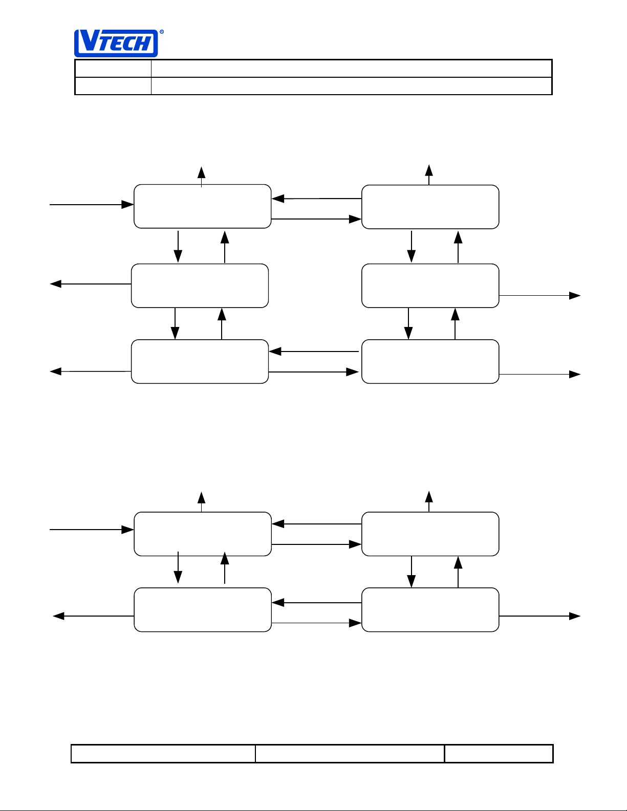
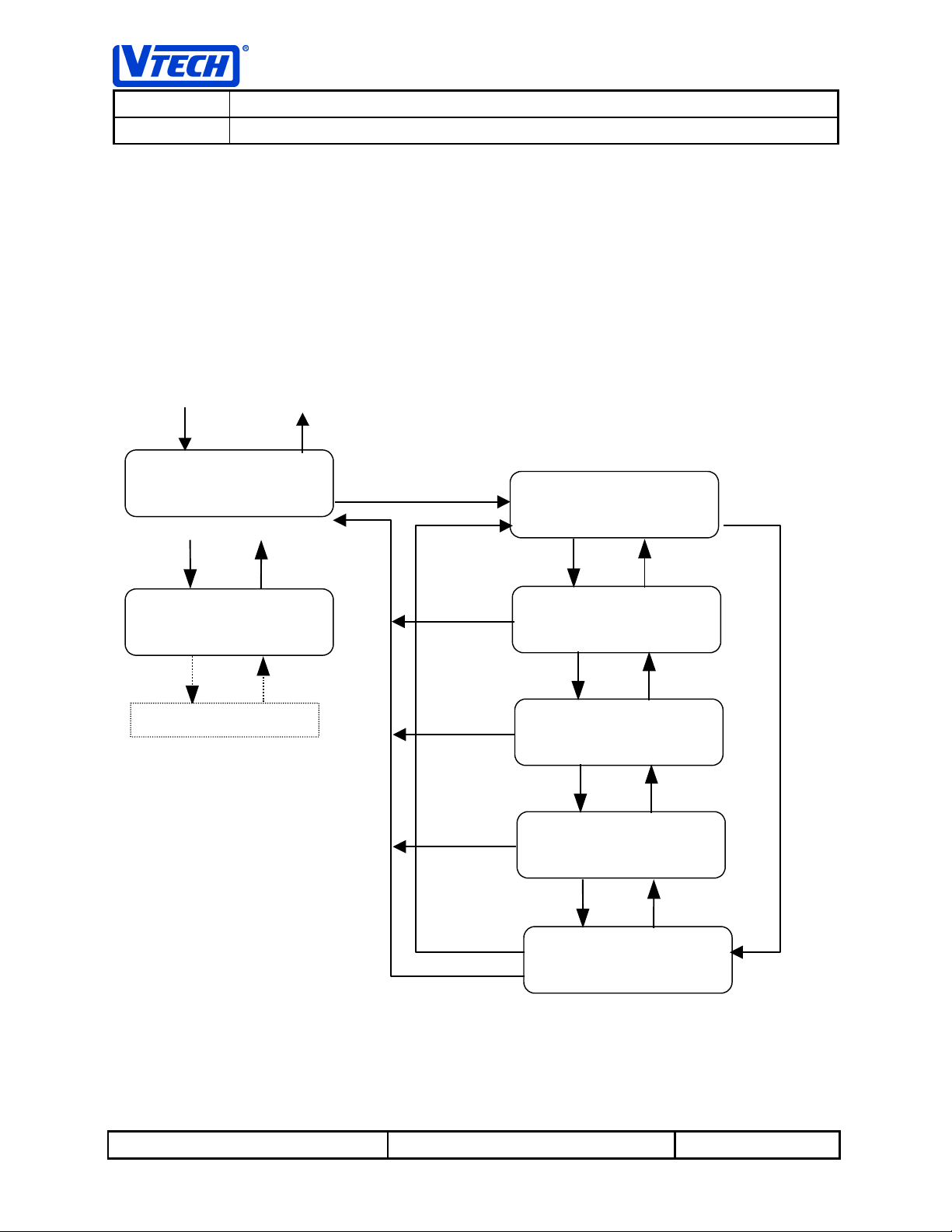
3.2.1 On Hook State Menus
The following diagram shows the menu sequence available when the telephone is on hook.
PHONE
Press
OFF
Key to Exit
Press
SELECT
Key
Press
OFF
Key to Exit
REDIAL
REDIAL
REDIALREDIAL
MEMORY
MEMORY
MEMORYMEMORY
PHONE
or
Press
Press
▼
▲
Key
Key
SETUP MODE
SETUP MODE
SETUP MODESETUP MODE
or
Press ▲ Key
PHONE
Press
OFF
Key to Exit
Press
OFF
Key to Exit
3.2.2 Off Hook State Menus
The following menus are displayed whenever the phone is off hook.
SELECT
Press
PHONE
or
CID
CID
CIDCID
MEMORY
MEMORY
MEMORYMEMORY
Press ▲ Key
or
SPEED DIAL
SPEED DIAL
SPEED DIALSPEED DIAL
MEMORY
MEMORY
MEMORYMEMORY
Press
OFF
Key to Return To Call
Key
CALL HOLD
CALL HOLD
CALL HOLDCALL HOLD
Figure 1 – MENU SEQUENCE IN THE ON HOOK STATE
PHONE
or
Press
Press
▼
▼
Key
Key
Press ▼ Key
Press
▲
Press ▲ Key
Key
Press ▼ Key
CLEAR
CLEAR
CLEARCLEAR
MEMORY
MEMORY
MEMORYMEMORY
Press ▼ Key
PROGRAM
PROGRAM
PROGRAMPROGRAM
SPEED DIAL
SPEED DIAL
SPEED DIALSPEED DIAL
Press
OFF
SPEED DIAL
SPEED DIAL
SPEED DIALSPEED DIAL
PHONE
Key to Exit
or
Press
Press
▲
▲
Key
Press
OFF
Key
Press
OFF
PHONE
Key to Exit
PHONE
Key to Exit
or
or
FEATURE
FEATURE
FEATUREFEATURE
Press ▲ Key
PHONE
Press
OFF
Key to Exit
This document is proprietary to V
Specifications are preliminary and are subject to change without notice.
or
REDIAL
REDIAL
REDIALREDIAL
MEMORY
MEMORY
MEMORYMEMORY
Figure 3.1.2 - MENU SEQUENCE IN THE OFF HOOK STATE
Reference: PRC 00DM Revision: 3.0 Page: 15 of 56
Press
TECH ENGINEERING CANADA LTD
▼
Press
Key
Press
Key
▼
Press ▼ Key
Key
▲
. 23624
MEMORY
MEMORY
MEMORYMEMORY
Press ▼ Key
CID
CID
CIDCID
MEMORY
MEMORY
MEMORYMEMORY
Press
▲
Key
Press
OFF
PHONE
Key to Exit
or
Page 16
TECH ENGINEERING CANADA LIMITED
V
TITLE PDL GX Internal Product Specification
MODEL PDL GX
In general, to exit from the current menu/mode the user can press the
back one step.
Press
SELECT
SELECT
R1 2573356
R1 2573356
R1 2573356R1 2573356
Press ▲ Key
OFF
R2 2573356
R2 2573356
R2 2573356R2 2573356
key while on hook in idle mode will bring up
For example, using the diagram below, pressing the
the “REDIAL MEMORY” menu. Subsequent presses of the ▲▼ keys will allow the user to navigate
through the other menu items. If the user presses the
MEMORY” is displayed, the user will enter the redial memory function. Pressing the ▲▼ keys while in
this menu will allow the user to review the last 5 numbers dialed. Pressing the
within this state will return the user back up to the “REDIAL MEMORY” main menu item. Subsequent
presses of the ▲▼ keys will allow the user to navigate through the other menu items. Pressing the
key will exit the user from the main menu and return the user to the idle mode.
OFF
Press
REDIAL
REDIAL
REDIALREDIAL
MEMORY
MEMORY
MEMORYMEMORY
Press ▲ Key
CID
CID
CIDCID
SELECT
Key
Press
Key to Exit
to Idle Mode
Press
▼
Key
Press
SELECT
OFF
key; this will bring the user
key when the menu item “REDIAL
OFF
key anytime while
Press
▼
Key
OFF
MEMORY
MEMORY
MEMORYMEMORY
Press ▲ Key
OTHER MENU ITEMS
3.2.3 Mode Timeout
The handset will have a built in menu display timeout feature whereby if it detects that no key has been
pressed within 30 seconds, it will exit the current menu item and return to the appropriate on hook idle or
off hook state. The exception to this is when the phone call is placed on hold. If a call is on hold, the call
will remain on hold until the user manually takes it off hold or cradles the handset.
Press
▼
Key
Press
Press ▲ Key
OFF
Press
Press ▲ Key Press ▼ Key
OFF
Press
Press ▲ Key
Press ▲ Key
OFF
R3 2573356
R3 2573356
R3 2573356R3 2573356
R4 2573356
R4 2573356
R4 2573356R4 2573356
R5 2573356
R5 2573356
R5 2573356R5 2573356
Press
Press
▼
▼
Key
Key
Reference: PRC 00DM Revision: 3.0 Page: 16 of 56
This document is proprietary to V
Specifications are preliminary and are subject to change without notice.
TECH ENGINEERING CANADA LTD
. 23624
Page 17
TECH ENGINEERING CANADA LIMITED
V
TITLE PDL GX Internal Product Specification
MODEL PDL GX
3.3 Dial Modes
3.3.1 Pre-Seizure (On-Hook) Dialing or Pre-Dial
Pre-Seizure dialing or Pre-dial refers to a mode of operation where the user enters a phone number or
recalls a number from memory to be dialed prior to going off hook or seizing the line.
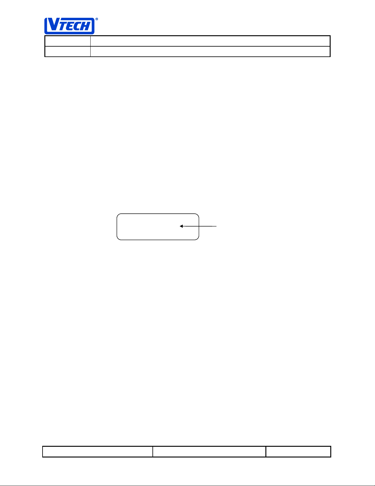
3.3.1.1 Pre-Dial Digit Entry and Editing
When the handset is idle and in on hook mode, the user can enter the digits of the phone number using
the keys 0 through 9 and the ✼ and # keys. If a dial pause is required in the phone number string, the
user can press and hold the # key. A P will be displayed after 1 second and this indicates a pause interval
of 1 second. A total of 20 digits can be entered using pre-dial.
To delete a digit the user can press the ▼ key. The digit to the left of the cursor will be deleted. The
cursor is always positioned to right of the last digit on the display. To delete the entire display, press the
OFF
key.
The following shows a sample display of a user entered phone number.
92573356_
92573356_
92573356_ 92573356_
Note: The on hook status is indicated by the cursor as an underscore when pre-dialing
As a general rule in pre-dial mode, the user can append to the displayed pre-dial digits with a phone
number recalled from CID, Speed Dial or Redial memory up to the maximum of 20 digits.
To dial the telephone number displayed on the LCD, press the
On Hook
Cursor
PHONE
key.
Reference: PRC 00DM Revision: 3.0 Page: 17 of 56
This document is proprietary to V
Specifications are preliminary and are subject to change without notice.
TECH ENGINEERING CANADA LTD
. 23624
Page 18

TECH ENGINEERING CANADA LIMITED
V
TITLE PDL GX Internal Product Specification
MODEL PDL GX
3.3.1.2 Pre-Dial Example
Phone State: On Hook
1. User enters phone number 9 257 3356:
92573356_
92573356_
92573356_ 92573356_
2. User wishes to correct the number to enter a dial pause after
the 9. The user presses the ▼ key 7 times to put the cursor
after the 9 digit :
3. Press and hold the # key for 1 second to insert a dial pause:
4. User re-enters the rest of the digits 257 3356:
5. User presses
PHONE
key to go off-hook and complete call:
9_
9_
9_ 9_
9P_
9P_
9P_ 9P_
9P2573356_
9P2573356_
9P2573356_ 9P2573356_
92573356\
92573356\
92573356\ 92573356\
Reference: PRC 00DM Revision: 3.0 Page: 18 of 56
This document is proprietary to V
Specifications are preliminary and are subject to change without notice.
TECH ENGINEERING CANADA LTD
. 23624
Page 19

TECH ENGINEERING CANADA LIMITED
V
TITLE PDL GX Internal Product Specification
MODEL PDL GX
3.3.2 Post-Seizure Dialing (Off-Hook) or Live Dial
Post-Seizure dialing or Live Dial refers to a mode of operation where the user goes off-hook or seizes the
line before entering the phone number or recalling a number from memory to be dialed. This type of
dialing is the normal method used in most corded telephones.
Live Dial or off-hook mode is indicated by a solid block cursor as shown in the example display below:
92573356\
92573356\
92573356\ 92573356\
In Live Dial the user can only recall telephone numbers from memory. No programming/editing functions
are allowed in Live-dial.
When the user takes the phone off hook without pre-dial digits on the display, the message ‘PHONE ON’
will be shown.
PHONE ON
PHONE ON
PHONE ONPHONE ON
The IN USE/CHARGING LED on the base will be lit
telephone line is off-hook. As the user manually enters digits the corresponding DTMF tone will be
generated and remain on for the duration the key is held when the dial mode is set to TONE , or, if the dial
mode is set to PULSE, the pulse digits will be dialed. A
the user of the manual entry.
GREEN
KEYCLICK
Solid Block Cursor
Indicates Off-Hook
to indicate the handset is in use and the
will also be generated to acknowledge
3.4 Using SELECT or PHONE key When Recalling Numbers From Memory
The cordless telephone supports “What You See Is What You Get“ (WYSIWYG) dialing when a user
recalls any dialing memory location while in pre-dial mode and presses the
SELECT
This feature allows the user to scroll through any memory recall locations (e.g. CID Recall, Last Number
Redial and Speed Dial) and select the number to be dialed. By pressing the
mode only, the number as shown on the recall display will be dialed exactly as shown. This feature
prevents any dialing errors caused by accidentally leaving digits on the pre-dial display prior to making the
memory recall selection.
If a user wishes to recall a memory location for further editing in pre-dial mode, the user can always press
the
the memory recall.
This document is proprietary to V
Specifications are preliminary and are subject to change without notice.
key.
SELECT
key to recall the number and append it to any digits already entered on the display prior to
Reference: PRC 00DM Revision: 3.0 Page: 19 of 56
TECH ENGINEERING CANADA LTD
. 23624
PHONE
PHONE
key instead of the
key when in pre-dial
Page 20

TECH ENGINEERING CANADA LIMITED
V
TITLE PDL GX Internal Product Specification
MODEL PDL GX
If a user recalls a memory location when in live-dial mode and presses either the
the number recalled will be immediately dialed in addition to any digits previously dialed during this call.
3.4.1 Pre-Dial Recall Example Using PHONE Key (WYSIWYG)
1. User enters a few digits in pre-dial mode (e.g. 52)
2. The user recalls a number from a redial location R2 which has
the number 3334422 stored in it. (See Section 3.6.1
Review/Recalling Most Recently Dialed Numbers from Redial
Memory)
3. User presses
are cleared from the pre-dial display, the phone goes off-hook
and the number 3334422 is immediately dialed.
3.4.2 Pre-Dial Recall Using SELECT Key
PHONE
key. The previously entered digits 52
52_
52_
52_ 52_
R2 3334442
R2 3334442
R2 3334442R2 3334442
3334442\
3334442\
3334442\ 3334442\
PHONE
SELECT
or
key,
1. User enters a few digits in pre-dial mode (e.g. 52)
2. The user recalls a number from a redial location R2 which has
the number 3334422 stored in it. (See Section 3.6.1
Review/Recalling Most Recently Dialed Numbers from Redial
Memory)
3. User presses
appended to the previously entered digits as shown:
SELECT
key. The redial number is recalled and
52_
52_
52_ 52_
R2 3334442
R2 3334442
R2 3334442R2 3334442
523334442_
523334442_
523334442_ 523334442_
Reference: PRC 00DM Revision: 3.0 Page: 20 of 56
This document is proprietary to V
Specifications are preliminary and are subject to change without notice.
TECH ENGINEERING CANADA LTD
. 23624
Page 21

TECH ENGINEERING CANADA LIMITED
V
TITLE PDL GX Internal Product Specification
MODEL PDL GX
3.4.3 Live-Dial Recall Using PHONE or SELECT Key
1. User presses
telephone number in live-dial mode (e.g. 2245555):
2. The user recalls a number from a redial location R2 which has
the number 3334422 stored in it. (See Section 3.6.1
Review/Recalling Most Recently Dialed Numbers from Redial
Memory).
3. User presses
The recalled number is dialed out and the display shows the
previously dialed number plus the appended recalled redial
number.
PHONE
PHONE
key to go off-hook and dials the a
SELECT
or
key while still in live-dial.
2245555\
2245555\
2245555\ 2245555\
R2 3334442
R2 3334442
R2 3334442R2 3334442
2455553334
2455553334
2455553334 2455553334
442\
442\
442\ 442\
3.5 Placing A Call on Hold
The user can place the call on HOLD when in Live-dial model. This keeps the connection to the
destination but with the incoming, and outgoing audio muted. An example of how to place a call on HOLD
is shown below:
Phone State: In Use Mode (Off-Hook)
4. Press the
following will be displayed:
SELECT
key in order to activate the menu. The
CALL HOLD
CALL HOLD
CALL HOLDCALL HOLD
FEATURE
FEATURE
FEATUREFEATURE
2. The user presses the
call on HOLD and the following will be displayed while the call is
on hold:
The IN USE/CHARGING LED on the base unit will also flash
condition at the base station.
To cancel the hold condition the user can simply press the
has the option to terminate the current call on hold by simply cradling the handset into the base unit.
Reference: PRC 00DM Revision: 3.0 Page: 21 of 56
This document is proprietary to V
Specifications are preliminary and are subject to change without notice.
SELECT
key again in order to place the
TECH ENGINEERING CANADA LTD
CALL ON HOLD
CALL ON HOLD
CALL ON HOLDCALL ON HOLD
GREEN
PHONE
. 23624
twice per second to indicate the hold
key or the
OFF
key. The user also
Page 22

TECH ENGINEERING CANADA LIMITED
V
TITLE PDL GX Internal Product Specification
MODEL PDL GX
3.6 Last Number Redial
3.6.1 Review/Recalling Most Recently Dialed Numbers from Redial Memory
To access the Redial memory select “REDIAL MEMORY” from the menu. There are 5 Redial locations,
which will store the last five telephone numbers dialed. The memory is organized in order of the most
recently dialed number in location 1 to the least recent dialed in location 5.
An example of a redial telephone number presented in the display is shown below:
R1 2573356
R1 2573356
R1 2573356R1 2573356
Redial Location
Number
A Redial phone number can be up to a maximum of 20 digits.
The user can scroll through the five Redial locations using the ▼ or ▲ keys.
SELECT
REDIAL
REDIAL
REDIALREDIAL
MEMORY
MEMORY
MEMORYMEMORY
Press
Press
Key
▲
R1 2573356
R1 2573356
R1 2573356R1 2573356
Press ▲ Key
R2 2573356
R2 2573356
R2 2573356R2 2573356
Press ▲ Key
R3 2573356
R3 2573356
R3 2573356R3 2573356
Press ▲ Key
Press
Saved Phone
Number
Key
▼
Press
Press
▼
▼
Key
Key
Press ▼ Key
R4 2573356
R4 2573356
R4 2573356R4 2573356
Press ▲ Key
R5 2573356
R5 2573356
R5 2573356R5 2573356
To recall the Redial number for further editing when in pre-dial mode, press the
Section 3.3.1.1 Pre-Dial Digit Entry and Editing and Section 3.4 Using SELECT or PHONE key When
Recalling Numbers From Memory for more details.
Reference: PRC 00DM Revision: 3.0 Page: 22 of 56
This document is proprietary to V
Specifications are preliminary and are subject to change without notice.
TECH ENGINEERING CANADA LTD
. 23624
Press
Key
▼
SELECT
key. Refer to
Page 23

TECH ENGINEERING CANADA LIMITED
V
TITLE PDL GX Internal Product Specification
MODEL PDL GX
Note: When Redial numbers are recalled from memory in pre-dial mode using the SELECT key,
they are automatically appended to any digits already entered on the display. To ensure that only
the redial number will be dialed, the user should ensure that no digits appear in the pre-dial
display before recalling the redial number entry. See
When Recalling Numbers From Memory
for more details.
Section 3.4 Using SELECT or PHONE key
After recalling and editing the desired redial number, the user can press the
and immediately dial the number on the display.
While in pre-dial mode, the user can directly recall and dial the desired redial number, by scrolling to the
desired redial location and then pressing the
previously entered pre-dial digits, go off-hook, and immediately dial the number in the redial location
exactly as displayed.
When recalling redial numbers in live-dial mode, press either the
will immediately dial the number in the selected redial location. Note that in live-dial mode, any recalled
redial number will be appended to any digits already dialed.
To exit from Redial review without recalling the telephone number, press the
returned to the menu selection mode.
3.6.1.1 Redial Example Using PHONE key from Pre-Dial Mode:
Assume that the user has made 4 previous telephone calls to the following numbers in the following order:
233 4566, 876 1356 , 455 5677 and 257 3356.
Phone State: Idle Mode (On-Hook).
1. To recall the 3rd most recent dialed number from the redial
memory, the user first presses the
following menu item is displayed:
SELECT
PHONE
key and the
key. This will cause the telephone to clear any
PHONE
PHONE
key or the
REDIAL
REDIAL
REDIALREDIAL
MEMORY
MEMORY
MEMORYMEMORY
SELECT
OFF
key. The user is then
key to go off hook
key and this
2. The user presses the
REDIAL MEMORY function. The phone number of the last call
made is displayed:
3. To select the 3rd most recently dialed number, the user scrolls
back through the redial list by pressing the ▲ key until record
number R3 is found:
4. The user presses the
complete the call.
Reference: PRC 00DM Revision: 3.0 Page: 23 of 56
This document is proprietary to V
Specifications are preliminary and are subject to change without notice.
SELECT
PHONE
key again in order to enter the
key to dial the number and
TECH ENGINEERING CANADA LTD
. 23624
R1 2573356
R1 2573356
R1 2573356R1 2573356
R3 8761356
R3 8761356
R3 8761356R3 8761356
8761356\
8761356\
8761356\ 8761356\
Page 24

TECH ENGINEERING CANADA LIMITED
V
TITLE PDL GX Internal Product Specification
MODEL PDL GX
3.6.1.2 Redial Example Using PHONE key from Live-Dial Mode:
Assume that the user has made 4 previous telephone calls to the following numbers in the following order:
233 4566, 876 1356 , 455 5677 and 257 3356.
Phone State: Live Dial Mode (Off-Hook) and user has not entered any digits.
1. To recall the 3rd most recent dialed number from the redial
memory, the user first presses the
following menu item is displayed:
2. The user presses the
REDIAL MEMORY function. The phone number of the last call
made is displayed:
3. To select the 3rd most recently dialed number, the user scrolls
back through the redial list by pressing the ▲ key until record
number R3 is found:
4. The user presses the
complete the call.
3.6.2 Storing Redial Records
Phone numbers are stored in redial memory only when the phone goes off hook and the call is made. Any
subsequent digits entered after the phone has gone off-hook (post line seizure or live dialing) will be
appended to the number and saved in the redial memory up to the maximum of 20 digits.
If a user enters a phone number using pre-dial and does not go off-hook, the number will not be saved in
redial memory.
SELECT
PHONE
SELECT
key again in order to enter the
key to dial the number and
key and the
REDIAL
REDIAL
REDIALREDIAL
MEMORY
MEMORY
MEMORYMEMORY
R1 2573356
R1 2573356
R1 2573356R1 2573356
R3 8761356
R3 8761356
R3 8761356R3 8761356
8761356\
8761356\
8761356\ 8761356\
Any subsequent dialing digits entered after the
combination of the first 20 digits whether pre-dialed and live-dialed will be stored; In the case where there
are less than 20 digits, storage will be triggered by activation of a line flash or an
After a hook switch flash, the numbers previously dialed are immediately saved in the current redial
memory location and all subsequent numbers after the flash are recorded in a new redial memory
location.
Reference: PRC 00DM Revision: 3.0 Page: 24 of 56
This document is proprietary to V
Specifications are preliminary and are subject to change without notice.
TECH ENGINEERING CANADA LTD
PHONE
key is pressed (live dialing) will also be stored. A
OFF
key press.
. 23624
Page 25

TECH ENGINEERING CANADA LIMITED
V
TITLE PDL GX Internal Product Specification
MODEL PDL GX
3.7 Incoming Calls
3.7.1 Ringing
Both the base and handset have provision to indicate an incoming call once a power ringing signal from
the CO has been detected. The base
power ringing signal. If the handset is idle, and the user has not pre-dialed any digits, the handset will
display:
The LCD back light will come on as soon as ringing has been detected and ringing and will follow the
power ring signal cadence. This message will persist while the CO power ringing signal is active and for 5
more seconds after the last ring signal is received. However, the message will be immediately overwritten
by an incoming CID message if received. The handset will ring using the programmed ringer type and
level selected in Setup Mode.
3.7.2 Answering the Incoming Call
The user is provided with a quick method of answering the incoming call by pressing any key on the
handset (
menus active). This feature allows the user to answer the call without having to find the
which may be difficult in a low ambient light condition.
except the OFF key)
once ringing has been detected and if the phone is in the idle state (no
IN USE
INCOMING
INCOMING
INCOMINGINCOMING
CALL
CALL
CALLCALL
LED will flash at a rate of 16 Hz during the ON cycle of the
PHONE
key
If the user has any menus are active when the phone rings, the user must press the PHONE key to
answer the call.
3.7.3 Terminating the Incoming Call
The user can press the
the handset back into its base. Pressing the
call since it will return the user to the menu.
When the handset is returned to the cradle the base CHARGING LED will be lit RED to indicate the
handset is being charged.
OFF
key when the telephone is off hook to terminate the call or by simply cradling
OFF
key in any menu selection mode will not hang up the
Reference: PRC 00DM Revision: 3.0 Page: 25 of 56
This document is proprietary to V
Specifications are preliminary and are subject to change without notice.
TECH ENGINEERING CANADA LTD
. 23624
Page 26

TECH ENGINEERING CANADA LIMITED
V
TITLE PDL GX Internal Product Specification
MODEL PDL GX
3.8 Calling Line ID Functions
The telephone is capable of decoding, saving and displaying up to 50 calling line ID numbers (CID).
Calling line ID is a paid feature provided by the telephone company (TELCO) which sends the telephone
number of the caller to the user so that he can identify who is calling before answering the call.
3.8.1 CID Type I
Upon successful reception of the CID data sent by the CO between the first and the second power ringing,
the display on the handset will show the name and number field received appropriately.
Name Field: The
first 12 characters
of this field are
displayed.
VTECH ELECTR
VTECH ELECTR
VTECH ELECTRVTECH ELECTR
604-273-5131
604-273-5131
604-273-5131604-273-5131
Number Field: Hyphenation is only
inserted when the number received
is 10 digits
This display will persist for the duration of ringing and will remain active for 5 seconds after the last
detected power ring on signal.
Once new valid CID data is received, the new calls counter will be incremented by one.
The name and number field may also display ‘PRIVATE’ or ‘UNAVAILABLE’ if it’s blocked or is not
provided by the CO. If erroneous CID data as is received (as determined by a checksum error) the
following message will be displayed:
CALL ID
CALL ID
CALL IDCALL ID
ERROR
ERROR
ERRORERROR
3.8.2 Call Forward Indicator
In some cases, a user may receive calls forwarded from another telephone. To indicate this a ‘CF’ is
displayed in the first character of the number field as shown below:
Name Field: The first 12
characters of this field are
VTECH ELECTR
VTECH ELECTR
VTECH ELECTRVTECH ELECTR
Call Forward Indicator
This feature helps a user to identify that the call he received was not made directly to this telephone.
604273-5131
604273-5131
604273-5131 604273-5131
displayed.
Number Field: Hyphenation is only
inserted when the number received
is 10 digits
This feature can be disabled via a bit flag in EEPROM during factory programming to support those
customers who do not require the feature.
Reference: PRC 00DM Revision: 3.0 Page: 26 of 56
This document is proprietary to V
Specifications are preliminary and are subject to change without notice.
TECH ENGINEERING CANADA LTD
. 23624
Page 27

TECH ENGINEERING CANADA LIMITED
V
TITLE PDL GX Internal Product Specification
MODEL PDL GX
3.8.3 New Calls Indicator
The handset will display the number of new calls received this will be based on the received CID data.
The new calls will count the number of calls received since last CID review. Refer to Section 3.8.1
Review/Recall Telephone Numbers from CID Memory. Once the user reviews the CID records the New
Calls status will be cleared.
The following shows an example of a single and multiple new calls display. The new calls display will
always displayed on the top line when the handset is idle. This message has the lowest priority and may
be over written by other messages.
1 NEW CALL
1 NEW CALL
1 NEW CALL1 NEW CALL
3.8.3.1 New Calls LED Indicator Option
The New Calls LED indicator on the base will flash at a rate of twice per second, on models equipped with
this indicator. The base indicator will match the handset New Calls status.
3 NEW CALLS
3 NEW CALLS
3 NEW CALLS3 NEW CALLS
3.8.4 CID Type II
The telephone is capable of receiving Call W aiting CID type II. If during a normal phone call, another call
comes in with CID information, alerting tones (subscriber alert signal tone or
handset earpiece to notify the user of the 2nd call. The phone will mute both audio paths, acknowledge
back to the CO via a DTMF tone and then receive, decode and display the new CID information.
The new CID information will be displayed in the same manner as defined in Section 3.8.1 CID Type I.
The new CID information will be displayed for 10 seconds and will then be stored in E
CID information will also cause the New Calls counter to be incremented.
3.8.5 Review/Recall Telephone Numbers from CID Memory.
When the telephone is on-hook, the CID information stored in memory can be reviewed or recalled. To
access the CID memory, press the
“CID MEMORY” from the menu.
A total of up to 50 CID records can be saved. Any saved CID records can be reviewed and recalled. The
user can scroll through the CID records using the ▼ or ▲ keys. Any empty CID memory locations will
not be displayed. For example, if CID records 01 through 18 are active and the remaining CID records are
empty, then if the user presses the ▲ key while displaying record #18, the next record displayed will be
record #01.
Upon entering the “CID MEMORY” menu item, the most recent record (record #1) will be displayed. The
records are saved such that the most recent record is displayed first and the oldest record is displayed
last. The top line of the display will show the record number and the name (if it exists) and the second line
will show the phone number (if it exists). An example display is shown below:
SELECT
key to bring up the menu. Then use the ▲▼ keys to select
SAS
) will be heard in the
2
PROM. This new
Reference: PRC 00DM Revision: 3.0 Page: 27 of 56
This document is proprietary to V
Specifications are preliminary and are subject to change without notice.
TECH ENGINEERING CANADA LTD
. 23624
Page 28

TECH ENGINEERING CANADA LIMITED
V
TITLE PDL GX Internal Product Specification
MODEL PDL GX
CID Name Field
CID Memory Location
Number
The name and the phone number field may have “PRIVATE” or “UNAVAILABLE” instead. This will
depend on the CID information received from the CO.
In the above example the most right character on the top line indicates that there are more characters in
the name field. To view the entire name field the user can press and hold the 9 key.
01
01 VTECH EL~
0101
273-5131
273-5131
273-5131273-5131
VTECH EL~
VTECH EL~VTECH EL~
01 VTECH ELE
01 VTECH ELE
01 VTECH ELE01 VTECH ELE
CTRNC
CTRNC
CTRNCCTRNC
Arrow indicates there are more
characters in Name Field
CID Phone Number
Field
The date and time stamp of the CID record can also be viewed by pressing and holding down the 7 key.
The display format of the telephone number with time stamp is shown below.
Time Field
Call Forward Indicator
(Optional)
12:30P JUN01
12:30P JUN01
12:30P JUN0112:30P JUN01
273-5131
273-5131
273-5131 273-5131
AM/PM Indicator
Date Field
Phone Number Field
Reference: PRC 00DM Revision: 3.0 Page: 28 of 56
This document is proprietary to V
Specifications are preliminary and are subject to change without notice.
TECH ENGINEERING CANADA LTD
. 23624
Page 29

TECH ENGINEERING CANADA LIMITED
V
TITLE PDL GX Internal Product Specification
MODEL PDL GX
3.8.5.1 CID Number Recall Options
To recall the telephone number from the CID record for editing or dialing the user can press the following
keys to select the dial string options:
Phone State: Idle Mode (On-Hook) and no digits currently entered using pre-dial mode.
Assume that the following CID record exists:
01 VTECH EL~
01 VTECH EL~
01 VTECH EL~01 VTECH EL~
604-273-5131
604-273-5131
604-273-5131604-273-5131
1. Press the
displayed and append them to the digits previously entered on
the display. This can be used for Direct Dial Numbers where the
telephone company sends the exact number needed to dial the
caller. The following will be displayed:
2. Press the
displayed, go off-hook and dial the CID number. This can be
used for Direct Dial Numbers where the telephone company
sends the exact number needed to dial the caller:
3. Press the 1 key to recall the Long Distance Prefix (1) + Area
Code + Exchange Code + Line Code (e.g. 16042735131 -- 11
digits):
4. Press the 2 key to recall the Area Code + Exchange Code +
Line Code (e.g. 6042735131 -- 10 digits):
5. Press the 3 key to recall the Long Distance Prefix (1) +
Exchange Code + Line Code (e.g. 12735131 -- 8 digits):
6. Press the 4 key to recall the Exchange Code + Line Code (e.g.
2735131 -- 7 digits):
SELECT
PHONE
key to recall the number exactly as
key to recall the CID number exactly as
6042735131
6042735131
6042735131 6042735131
_
_
_ _
6042735131
6042735131
6042735131 6042735131
\
\
\ \
1604273513
1604273513
1604273513 1604273513
1_
1_
1_ 1_
6042735131
6042735131
6042735131 6042735131
_
_
_ _
12735131_
12735131_
12735131_ 12735131_
2735131_
2735131_
2735131_ 2735131_
NOTE: If the CO only sends a 7-digit phone number and the 2 key is pressed, the user will only get the
seven-digit phone number. If the 1 key is pressed in this case, a 1 digit will precede the 7 digit phone
number.
After recalling the desired CID number using the
PHONE
hook, pressing either
append it to any previously dialed digits.
To exit from memory review without recalling the phone number from the CID record, press the
The user is then returned to the “CID MEMORY” menu item.
This document is proprietary to V
Specifications are preliminary and are subject to change without notice.
key to go off hook and dial out the phone number displayed. If the telephone was already off-
SELECT, 1, 2, 3
Reference: PRC 00DM Revision: 3.0 Page: 29 of 56
TECH ENGINEERING CANADA LTD
or 4 will immediately dial the formatted CID number selected and
SELECT
key and format in pre-dial mode, press the
. 23624
OFF
key.
Page 30

TECH ENGINEERING CANADA LIMITED
V
TITLE PDL GX Internal Product Specification
MODEL PDL GX
3.8.6 Deleting a CID Record in Review Mode
While reviewing any of the CID record, the user has the ability to delete the current CID record in view.
The user presses and holds the 0 key and will be acknowledged with a
display the following message:
DELETE CALL?
DELETE CALL?
DELETE CALL?DELETE CALL?
0=YES OFF=NO
0=YES OFF=NO
0=YES OFF=NO0=YES OFF=NO
KEYCLICK
and the LCD will
To abort the deletion of the call record, the user must press the
the user must press the 0 key again. A
record followed by the message:
This message will be removed once deletion has completed. The user is then returned back to CID
review. The next oldest CID record will shift into the deleted location. For example if the user deletes
location 5, previous location 6 is shifted to 5, previous location 7 is shifted to location 6, and so on. To
clear all CID memory, refer to Section 3.10 Clearing CID, Speed Dial Memory and VMWI.
KEYCLICK
DELETING
DELETING
DELETINGDELETING
SINGLE CALL
SINGLE CALL
SINGLE CALLSINGLE CALL
will be generated to indicate the deletion of the CID
OFF
key. To proceed with the deletion,
Reference: PRC 00DM Revision: 3.0 Page: 30 of 56
This document is proprietary to V
Specifications are preliminary and are subject to change without notice.
TECH ENGINEERING CANADA LTD
. 23624
Page 31

TECH ENGINEERING CANADA LIMITED
V
TITLE PDL GX Internal Product Specification
MODEL PDL GX
3.8.7 Call Forward Display of Telephone Numbers
The following examples show how the incoming CID telephone number would be displayed for various
length telephone numbers:
NUMBER OF DIGITS IN
TELEPHONE NUMBER
7
8
9
10
11
WITHOUT CALL FORWARD
DISPLAY ENABLED
VTECH ELECTR
VTECH ELECTR
VTECH ELECTRVTECH ELECTR
273-5131
273-5131
273-5131273-5131
VTECH ELECTR
VTECH ELECTR
VTECH ELECTRVTECH ELECTR
1-273-5131
1-273-5131
1-273-51311-273-5131
VTECH ELECTR
VTECH ELECTR
VTECH ELECTRVTECH ELECTR
04-273-5131
04-273-5131
04-273-513104-273-5131
VTECH ELECTR
VTECH ELECTR
VTECH ELECTRVTECH ELECTR
604-273-5131
604-273-5131
604-273-5131604-273-5131
VTECH ELECTR
VTECH ELECTR
VTECH ELECTRVTECH ELECTR
1604273-5131
1604273-5131
1604273-51311604273-5131
WITH CALL FORWARD
DISPLAY ENABLED
VTECH ELECTR
VTECH ELECTR
VTECH ELECTRVTECH ELECTR
273-5131
273-5131
273-5131 273-5131
VTECH ELECTR
VTECH ELECTR
VTECH ELECTRVTECH ELECTR
1-273-5131
1-273-5131
1-273-5131 1-273-5131
VTECH ELECTR
VTECH ELECTR
VTECH ELECTRVTECH ELECTR
04273-5131
04273-5131
04273-5131 04273-5131
VTECH ELECTR
VTECH ELECTR
VTECH ELECTRVTECH ELECTR
604273-5131
604273-5131
604273-5131 604273-5131
VTECH ELECTR
VTECH ELECTR
VTECH ELECTRVTECH ELECTR
16042735131
16042735131
16042735131 16042735131
Reference: PRC 00DM Revision: 3.0 Page: 31 of 56
This document is proprietary to V
Specifications are preliminary and are subject to change without notice.
TECH ENGINEERING CANADA LTD
. 23624
Page 32

TECH ENGINEERING CANADA LIMITED
V
TITLE PDL GX Internal Product Specification
MODEL PDL GX
3.9 Speed Dial Functions
The telephone has 20 speed dial memory locations which can be programmed and recalled for quick
access to frequently dialed numbers.
3.9.1 Programming Speed Dial Memory
Programming the Speed Dial Memory is only allowed, in the on hook condition. The user may copy any
phone number on the display into any of the 20 locations in the Speed Dial memory. This means that the
user can enter the desired digits on the display (pre-dial), and then access the “PROGRAM SPEED DIAL”
menu item in order to store it into the Speed Dial Memory.
In general the user can recall a phone number from memory such as CID, Speed Dial or Redial onto the
display.
Once all the desired digits to be programmed are shown in the display the user can select the
“PROGRAM SPEED DIAL” menu item. An example programming sequence is shown as follows:
3.9.1.1 Program Speed Dial Example
Phone State: On hook
1. Enter or recall the following number to be programmed into
speed dial memory while the telephone is on hook.
2. Press
3. Use the ▲▼ keys to select the following menu item:
4. Press the
5. Enter the 2 digit speed dial memory location under which to
Immediately after entering the 2nd digit, the speed dial location
SELECT
menu item:
store the telephone number (e.g. 18):
will be programmed with the number 591 6678. If the speed
dial entry was correctly saved, a
generated.
key to display the menu:
SELECT
key to select the PROGRAM SPEED DIAL
CONFIRMATION TONE
will be
5916678_
5916678_
5916678_ 5916678_
REDIAL
REDIAL
REDIALREDIAL
MEMORY
MEMORY
MEMORYMEMORY
PROGRAM
PROGRAM
PROGRAMPROGRAM
SPEED DIAL
SPEED DIAL
SPEED DIALSPEED DIAL
PGM SPD DIAL
PGM SPD DIAL
PGM SPD DIALPGM SPD DIAL
LOCATION __
LOCATION __
LOCATION __LOCATION __
PGM SPD DIAL
PGM SPD DIAL
PGM SPD DIALPGM SPD DIAL
LOCATION 18
LOCATION 18
LOCATION 18LOCATION 18
If the user enters an invalid location number, an
will be generated.
Reference: PRC 00DM Revision: 3.0 Page: 32 of 56
This document is proprietary to V
Specifications are preliminary and are subject to change without notice.
TECH ENGINEERING CANADA LTD
ERROR TONE
. 23624
Page 33

TECH ENGINEERING CANADA LIMITED
V
TITLE PDL GX Internal Product Specification
MODEL PDL GX
6. The user can abort programming at any time by pressing the
OFF
key. In this case and
and the following will be displayed:
3.9.2 Review/Recall Telephone Number from Speed Dial Memory
To access the Speed Dial memory, select “SPEED DIAL MEMORY” from the menu. There are 20 speed
dial memory locations for recall or review. Upon entering the “SPEED DIAL MEMORY” menu item, the
user will be prompted with the following display:
The user can directly access any speed dialing location by entering a two digit location number or scroll
sequentially through the memory locations using the ▼ or ▲ keys.
ERROR TONE
SPEED DIAL
SPEED DIAL
SPEED DIALSPEED DIAL
LOCATION __
LOCATION __
LOCATION __LOCATION __
will be generated
PROGRAMMING
PROGRAMMING
PROGRAMMINGPROGRAMMING
INCOMPLETE
INCOMPLETE
INCOMPLETEINCOMPLETE
The following is an example display of a speed dial location:
Speed Dial
Location Number
The location number is displayed on the top left followed by the stored telephone number.
A total of 20 digits can be stored in any given location.
When the telephone is on-hook, the user can recall and append the speed dial number to any digits
already on the display by pressing the
and immediately dial the speed dial number as displayed.
If the telephone is already off-hook, the user can immediately recall the selected speed dial number by
pressing the
appended to any other digits previously dialed on this call.
In on-hook mode only, the user may recall the phone number for further editing (i.e., pre-dial) by pressing
SELECT
the
To exit from reviewing the Speed Dial review session, press the
“SPEED DIAL MEMORY“ menu item.
SELECT
key.
or
PHONE
S03 5551212
S03 5551212
S03 5551212S03 5551212
SELECT
key. The display will show the speed dial number recalled for dialing
key. The user can also press the
OFF
key. The user is then returned to the
Saved Phone
Number
PHONE
key to recall
Reference: PRC 00DM Revision: 3.0 Page: 33 of 56
This document is proprietary to V
Specifications are preliminary and are subject to change without notice.
TECH ENGINEERING CANADA LTD
. 23624
Page 34

TECH ENGINEERING CANADA LIMITED
V
TITLE PDL GX Internal Product Specification
MODEL PDL GX
3.9.2.1 Speed Dial Review Example
An example of a speed dial review is shown as follows:
Phone Mode: Off-Hook (Live Dial) and no previous digits have been dialed.
keys .
SELECT
SELECT
key and the following will be displayed:
key to select the “SPEED DIAL MEMORY”
1. Press the
.
2. Use the ▲▼ keys to select the following menu item:
3. Press the
menu item:
4. Directly enter the 2 digit speed dial memory location (e.g. 03):
5. Immediately after the 2nd digit is entered, the speed dial
number will be displayed:
6. The user can also review other speed dial locations using the
▲▼
CALL HOLD
CALL HOLD
CALL HOLDCALL HOLD
FEATURE
FEATURE
FEATUREFEATURE
SPEED DIAL
SPEED DIAL
SPEED DIALSPEED DIAL
MEMORY
MEMORY
MEMORYMEMORY
SPEED DIAL
SPEED DIAL
SPEED DIALSPEED DIAL
LOCATION __
LOCATION __
LOCATION __LOCATION __
SPEED DIAL
SPEED DIAL
SPEED DIALSPEED DIAL
LOCATION 03
LOCATION 03
LOCATION 03LOCATION 03
S03 5551212
S03 5551212
S03 5551212S03 5551212
S04 16044451
S04 16044451
S04 16044451S04 16044451
7. To make the call to this number press the
following will be displayed :
Reference: PRC 00DM Revision: 3.0 Page: 34 of 56
This document is proprietary to V
Specifications are preliminary and are subject to change without notice.
TECH ENGINEERING CANADA LTD
PHONE
key and the
. 23624
256
256
256256
1604445125
1604445125
1604445125 1604445125
6\
6\
6\ 6\
Page 35

TECH ENGINEERING CANADA LIMITED
V
TITLE PDL GX Internal Product Specification
MODEL PDL GX
3.9.3 Deleting a Speed Dial Location in Review Mode
While reviewing any of the Speed Dial location in on-hook mode, the user has the ability to delete the
speed dial location in view. The user presses and holds the 0 key and will be acknowledged with a
KEYCLICK
and the LCD will display the following message:
DELETE SPD?
DELETE SPD?
DELETE SPD?DELETE SPD?
0=YES OFF=NO
0=YES OFF=NO
0=YES OFF=NO0=YES OFF=NO
To abort the deletion of the speed dial location, the user must press the
deletion, the user must press the 0 key again. A
the speed dial followed by the message:
S01 DELETED
S01 DELETED
S01 DELETEDS01 DELETED
This message will be removed once deletion has completed. The user is then returned back to Speed
Dial review with the current location containing blanks signifying that it is empty. To clear all Speed Dial
memory refer to Section 3.10 Clearing CID, Speed Dial Memory and VMWI.
KEYCLICK
will be generated to indicate the deletion of
OFF
key. To proceed with the
Reference: PRC 00DM Revision: 3.0 Page: 35 of 56
This document is proprietary to V
Specifications are preliminary and are subject to change without notice.
TECH ENGINEERING CANADA LTD
. 23624
Page 36

TECH ENGINEERING CANADA LIMITED
V
TITLE PDL GX Internal Product Specification
MODEL PDL GX
3.10 Clearing CID, Speed Dial Memory and VMWI
The user can clear all of CID and Speed dial memory by selecting the ‘CLEAR MEMORY’ menu item.
Within this menu item the user can chose to clear either the CID Memory or the Speed Dial memory.
If the VMWI Option is supported, then the VMWI Indicator can also be cleared using the ‘CLEAR
MEMORY’ menu item. VMWI support is indicated using a status bit in EEPROM memory which is
programmed in the factory. See Section 3.12 Visual Message Waiting Indication (VMWI) for more
information on VMWI.
OFF
The
CLEAR menu item.
3.10.1 Clear Memory Menu Structure If VMWI Is Supported
CLEAR
CLEAR
CLEARCLEAR
MEMORY
MEMORY
MEMORYMEMORY
key can be pressed to cancel the clear function, the user will be returned to the appropriate
SELECT
Press
CLEAR CID
CLEAR CID
CLEAR CIDCLEAR CID
MEMORY
MEMORY
MEMORYMEMORY
Press ▲ Key
CLEAR
CLEAR
CLEARCLEAR
SPEED DIAL
SPEED DIAL
Press ▲ Key
3.10.2 Clear Memory Menu Structure If VMWI Is NOT Supported
SELECT
CLEAR
CLEAR
CLEARCLEAR
MEMORY
MEMORY
MEMORYMEMORY
Press
SPEED DIALSPEED DIAL
Press ▲ Key Press ▼ Key
CLEAR VMWI
CLEAR VMWI
CLEAR VMWICLEAR VMWI
CLEAR CID
CLEAR CID
CLEAR CIDCLEAR CID
MEMORY
MEMORY
MEMORYMEMORY
Press ▲ Key
Press
▼
Press
Key
▼
Press ▼ Key
Key
Press ▲ Key
CLEAR
CLEAR
CLEARCLEAR
SPEED DIAL
SPEED DIAL
SPEED DIALSPEED DIAL
Reference: PRC 00DM Revision: 3.0 Page: 36 of 56
This document is proprietary to V
Specifications are preliminary and are subject to change without notice.
TECH ENGINEERING CANADA LTD
. 23624
Press ▼ Key
Page 37

TECH ENGINEERING CANADA LIMITED
V
TITLE PDL GX Internal Product Specification
MODEL PDL GX
3.10.3 Clearing The Visual Message Waiting Indicator (If VMWI Option is Supported)
Note: If VMWI is supported as indicated by a status bit in EEPROM memory, then this sub-menu
item will be displayed.
The following example shows how to clear the VMW I:
Phone State: On Hook
1. Press the
be displayed:
2. Use the ▲▼ keys to select the CLEAR MEMORY menu item:
3. Press the
and the following will be displayed:
4. Use the ▲▼ keys to choose the desired memory item to clear.
In this example, the user will select CLEAR VMWI.
5. Press and hold the 0 key to select the item to be cleared.
After 1 second, the following message will be displayed to ask
the user to confirm the clear:
6. Press the 0 key again to clear the selected item. While the item
is being cleared, the following confirmation message.
SELECT
SELECT
key to activate the menu. The following will
key to enter the CLEAR MEMORY function
REDIAL
REDIAL
REDIALREDIAL
MEMORY
MEMORY
MEMORYMEMORY
CLEAR
CLEAR
CLEARCLEAR
MEMORY
MEMORY
MEMORYMEMORY
CLEAR CID
CLEAR CID
CLEAR CIDCLEAR CID
MEMORY
MEMORY
MEMORYMEMORY
CLEAR VMWI
CLEAR VMWI
CLEAR VMWICLEAR VMWI
CLEAR VMWI?
CLEAR VMWI?
CLEAR VMWI?CLEAR VMWI?
0=YES OFF=NO
0=YES OFF=NO
0=YES OFF=NO0=YES OFF=NO
CLEARING
CLEARING
CLEARINGCLEARING
VMWI
VMWI
VMWIVMWI
7. After 5 seconds the display will return to the CLEAR MEMORY
display item:
Note: Clearing VMWI will turn off both the message indicator on the handset and the LED indicator on the
base. This allows the user to clear the indicators if the Messaging service fails to update the no message
waiting status to the user.
Reference: PRC 00DM Revision: 3.0 Page: 37 of 56
This document is proprietary to V
Specifications are preliminary and are subject to change without notice.
TECH ENGINEERING CANADA LTD
. 23624
CLEAR
CLEAR
CLEARCLEAR
MEMORY
MEMORY
MEMORYMEMORY
Page 38

TECH ENGINEERING CANADA LIMITED
V
TITLE PDL GX Internal Product Specification
MODEL PDL GX
3.10.4 Clearing All CID Records
The following example shows how to clear all CID records:
Phone State: On Hook
1. Press the
be displayed:
2. Use the ▲▼ keys to select the CLEAR MEMORY menu item:
3. Press the
and the following will be displayed :
4. Press and hold the 0 key to select the item to be cleared.
After 1 second, the following message will be displayed to ask
the user to confirm the clear:
5. Press the 0 key again to clear the selected item. While the item
is being cleared, the following confirmation message.
6. After 5 seconds the display will return to the CLEAR MEMORY
display item:
SELECT
SELECT
key to activate the menu. The following will
key to enter the CLEAR MEMORY function
REDIAL
REDIAL
REDIALREDIAL
MEMORY
MEMORY
MEMORYMEMORY
CLEAR
CLEAR
CLEARCLEAR
MEMORY
MEMORY
MEMORYMEMORY
CLEAR CID
CLEAR CID
CLEAR CIDCLEAR CID
MEMORY
MEMORY
MEMORYMEMORY
CLR ALL CID?
CLR ALL CID?
CLR ALL CID?CLR ALL CID?
0=YES OFF=NO
0=YES OFF=NO
0=YES OFF=NO0=YES OFF=NO
CLEARING
CLEARING
CLEARINGCLEARING
ALL CID
ALL CID
ALL CIDALL CID
CLEAR
CLEAR
CLEARCLEAR
MEMORY
MEMORY
MEMORYMEMORY
Reference: PRC 00DM Revision: 3.0 Page: 38 of 56
This document is proprietary to V
Specifications are preliminary and are subject to change without notice.
TECH ENGINEERING CANADA LTD
. 23624
Page 39

TECH ENGINEERING CANADA LIMITED
V
TITLE PDL GX Internal Product Specification
MODEL PDL GX
3.10.5 Clearing All Speed Dial Locations
The following example shows how to clear all speed dial locations:
Phone State: On Hook
1. Press the
be displayed:
2. Use the ▲▼ keys to select the CLEAR MEMORY menu item:
3. Press the
and the following will be displayed :
4. Use the ▲▼ keys to choose the desired memory item to clear.
In this example, the user will select all speed dial locations.
5. Press and hold the 0 key to select the item to be cleared.
After 1 second, the following message will be displayed to ask
the user to confirm the clear:
6. Press the 0 key again to clear the selected item. While the item
is being cleared, the following confirmation message.
SELECT
SELECT
key to activate the menu. The following will
key to enter the CLEAR MEMORY function
REDIAL
REDIAL
REDIALREDIAL
MEMORY
MEMORY
MEMORYMEMORY
CLEAR
CLEAR
CLEARCLEAR
MEMORY
MEMORY
MEMORYMEMORY
CLEAR CID
CLEAR CID
CLEAR CIDCLEAR CID
MEMORY
MEMORY
MEMORYMEMORY
CLEAR
CLEAR
CLEARCLEAR
SPEED DIAL
SPEED DIAL
SPEED DIALSPEED DIAL
CLR ALL SPD?
CLR ALL SPD?
CLR ALL SPD?CLR ALL SPD?
0=YES OFF=NO
0=YES OFF=NO
0=YES OFF=NO0=YES OFF=NO
CLEARING
CLEARING
CLEARINGCLEARING
SPEED DIALS
SPEED DIALS
SPEED DIALSSPEED DIALS
7. After 5 seconds the display will return to the CLEAR MEMORY
display item:
Reference: PRC 00DM Revision: 3.0 Page: 39 of 56
This document is proprietary to V
Specifications are preliminary and are subject to change without notice.
TECH ENGINEERING CANADA LTD
. 23624
CLEAR
CLEAR
CLEARCLEAR
MEMORY
MEMORY
MEMORYMEMORY
Page 40

TECH ENGINEERING CANADA LIMITED
V
TITLE PDL GX Internal Product Specification
MODEL PDL GX
3.11 Flashing the Line/Switching Over to New Call
The user can press the
The flash feature is use for such features as call waiting, where pressing the phone key will cause a hook
switch flash and will signal to the CO to place the original call on hold and then switch over to the new call.
The new call will remain connected until the user activates another hook switch flash to switch back to the
first call again
PHONE
key to flash (or quickly break) the telephone line.
3.12 Visual Message Waiting Indication (VMWI)
The Visual Message Waiting Indication (VMWI) packet information transmitted by the CO is decoded by
the telephone. The status is displayed on the LCD on the handset. Visual Message Waiting information
is part of the Integrated Voice Messaging Services provided by the local telephone company if supported.
The VMWI display is an option which can be enabled or disabled via a status bit in EEPROM during
factory programming.
Upon detection of a message waiting status from the CO, the indication “MSG. W AITING” is displayed on
the second line of the LCD. However, this message will only be displayed when the handset is in idle
mode (on hook). This message indication is displayed with the New Calls indicator as shown below.
3 NEW CALLS
3 NEW CALLS
3 NEW CALLS3 NEW CALLS
MSG. WAITING
MSG. WAITING
MSG. WAITINGMSG. WAITING
3.12.1 VMWI LED Display Option
If the VMWI display is supported, it can also be optionally indicated on the base via the ‘MESSAGE
WAITING’ LED on those models equipped with this feature. It will flash at a rate of twice per second when
there is a message waiting at the service provider. This status can also be manually cleared – see
Section 3.10 Clearing CID, Speed Dial Memory and VMWI.
Reference: PRC 00DM Revision: 3.0 Page: 40 of 56
This document is proprietary to V
Specifications are preliminary and are subject to change without notice.
TECH ENGINEERING CANADA LTD
. 23624
Page 41

TECH ENGINEERING CANADA LIMITED
V
TITLE PDL GX Internal Product Specification
MODEL PDL GX
3.13 Setup Mode Options
There are three user configurable items, which are accessible through the “SETUP MODE” menu. All
settings in setup will be kept in non-volatile memory.
SETUP MODE
SETUP MODE
SETUP MODESETUP MODE
PHONE
SELECT
Press
SET RING
SET RING
SET RINGSET RING
TYPE
TYPE
TYPETYPE
Key
Press ▲ Key
Press
▼
Key
Press
OFF
Key to Exit
SET KEYCLICK
SET KEYCLICK
SET KEYCLICKSET KEYCLICK
or
Press
OFF
Press
PHONE
Key to Exit
Key
▲
or
SET RING
SET RING
SET RINGSET RING
VOLUME
VOLUME
VOLUMEVOLUME
Press
▼
Key
Press
Press
▲
▼
Key
Press ▼ Key
Key
SET DIAL
SET DIAL
SET DIALSET DIAL
TYPE
TYPE
TYPETYPE
Press
▲
Key
Press
OFF
PHONE
Key to Exit
or
Reference: PRC 00DM Revision: 3.0 Page: 41 of 56
This document is proprietary to V
Specifications are preliminary and are subject to change without notice.
TECH ENGINEERING CANADA LTD
. 23624
Page 42

TECH ENGINEERING CANADA LIMITED
V
TITLE PDL GX Internal Product Specification
MODEL PDL GX
3.13.1 Ring Type Setting (4 selection and OFF)
To set the ring type, select the “RING TYPE” menu item in setup mode. The user can use the ▲▼ keys to
select the ringer tone type from OFF and 1 through 4. The associated ringing tone will be activated for 2
seconds after a change in ringer type value is made. To exit the ring type setup, press the
return to the “RING TYPE” menu item. The original ring type setting prior to entering this mode will be
maintained unless the user confirms the desired setting by pressing the
ring type number.
The default factory setting is ring type 1.
The following example shows how to set the ringer type to 4.
Phone State: On Hook
SELECT
key after selecting the
OFF
key to
1. Press the
be displayed :
2. Use the ▲▼ keys to select the SETUP MODE menu item:
3. Press the
the following will be displayed:
4. Press the
setting and allow editing of the RING TYPE parameter:
5. Use the ▲▼ keys to select ringer type 4:
6. Press the
CONFIRMATION TONE
to select the next SETUP MODE item to program.
SELECT
SELECT
SELECT
SELECT
key to activate the menu. The following will
key to enter the SETUP MODE function and
key to display the current RING TYPE
key to save the new ringer type. A
will be generated. Use the ▲▼ keys
REDIAL
REDIAL
REDIALREDIAL
MEMORY
MEMORY
MEMORYMEMORY
SETUP MODE
SETUP MODE
SETUP MODESETUP MODE
SET RING
SET RING
SET RINGSET RING
TYPE
TYPE
TYPETYPE
RING
RING
RINGRING
TYPE x
TYPE x
TYPE xTYPE x
RING
RING
RINGRING
TYPE 4
TYPE 4
TYPE 4TYPE 4
SET RING
SET RING
SET RINGSET RING
TYPE
TYPE
TYPETYPE
Reference: PRC 00DM Revision: 3.0 Page: 42 of 56
This document is proprietary to V
Specifications are preliminary and are subject to change without notice.
TECH ENGINEERING CANADA LTD
. 23624
Page 43

TECH ENGINEERING CANADA LIMITED
V
TITLE PDL GX Internal Product Specification
MODEL PDL GX
3.13.2 Ringer Volume Control (High or Low)
To set the ringer volume, the user must select the “SET RING VOLUME” menu item in setup mode. The
display will show the current setting.
The user can set the ringer volume to high or low by pressing the ▲ or ▼ key. The selected ringer type will
activate for 2 seconds during the volume adjustment to allow the user to hear the selected level. To
confirm the desired setting press the
The default factory ringer volume setting is High.
The following display shows how to set the ringer volume to low.
Phone State: On Hook
SELECT
key, otherwise press
OFF
to exit setting the ringer volume.
1. Press the
be displayed :
2. Use the ▲▼ keys to select the SETUP MODE menu item:
3. Press the
the following will be displayed:
4. Use the ▲▼ keys to select the SET RING VOLUME menu item:
5. Press the
setting and allow editing of the RING VOLUME parameter:
6. Use the ▲▼ keys to select the LOW volume setting:
SELECT
SELECT
SELECT
key to activate the menu. The following will
key to enter the SETUP MODE function and
key to display the current RING VOLUME
REDIAL
REDIAL
REDIALREDIAL
MEMORY
MEMORY
MEMORYMEMORY
SETUP MODE
SETUP MODE
SETUP MODESETUP MODE
SET RING
SET RING
SET RINGSET RING
TYPE
TYPE
TYPETYPE
SET RING
SET RING
SET RINGSET RING
VOLUME
VOLUME
VOLUMEVOLUME
RING
RING
RINGRING
VOLUME HIGH
VOLUME HIGH
VOLUME HIGHVOLUME HIGH
RING
RING
RINGRING
7. Press the
CONFIRMATION TONE
to select the next SETUP MODE item to program.
This document is proprietary to V
Specifications are preliminary and are subject to change without notice.
SELECT
Reference: PRC 00DM Revision: 3.0 Page: 43 of 56
key to save the new ringer type. A
will be generated. Use the ▲▼ keys
TECH ENGINEERING CANADA LTD
. 23624
VOLUME LOW
VOLUME LOW
VOLUME LOWVOLUME LOW
SET RING
SET RING
SET RINGSET RING
VOLUME
VOLUME
VOLUMEVOLUME
Page 44

TECH ENGINEERING CANADA LIMITED
V
TITLE PDL GX Internal Product Specification
MODEL PDL GX
3.13.3 Dialing Type Selection (Tone or Pulse)
To set the dialing type, the user must select the “SET DIAL TYPE” menu item in setup mode. The display
will show the current setting. The user can setup the telephone for either TONE or PULSE dialing by
pressing the ▲ or ▼ key. To confirm the desired setting press the
exit setting the dialing type.
The default factory setting of dial type is Tone.
The following display shows how to set the dialing type to pulse.
Phone State: On Hook
SELECT
key, otherwise press
OFF
to
1. Press the
be displayed :
2. Use the ▲▼ keys to select the SETUP MODE menu item:
3. Press the
the following will be displayed:
4. Use the ▲▼ keys to select the SET DIAL TYPE menu item:
5. Press the
and allow editing of the DIAL TYPE parameter:
6. Use the ▲▼ keys to select the PULSE setting:
SELECT
SELECT
SELECT
key to activate the menu. The following will
key to enter the SETUP MODE function and
key to display the current DIAL TYPE setting
REDIAL
REDIAL
REDIALREDIAL
MEMORY
MEMORY
MEMORYMEMORY
SETUP MODE
SETUP MODE
SETUP MODESETUP MODE
SET RING
SET RING
SET RINGSET RING
TYPE
TYPE
TYPETYPE
SET DIAL
SET DIAL
SET DIALSET DIAL
TYPE
TYPE
TYPETYPE
DIAL TYPE
DIAL TYPE
DIAL TYPEDIAL TYPE
TONE
TONE
TONETONE
DIAL TYPE
DIAL TYPE
DIAL TYPEDIAL TYPE
7. Press the
CONFIRMATION TONE
keys to select the next SETUP MODE item to program.
This document is proprietary to V
Specifications are preliminary and are subject to change without notice.
SELECT
Reference: PRC 00DM Revision: 3.0 Page: 44 of 56
key to save the new ringer type. A
will be generated. Use the
TECH ENGINEERING CANADA LTD
▲▼
. 23624
PULSE
PULSE
PULSEPULSE
SET DIAL
SET DIAL
SET DIALSET DIAL
TYPE
TYPE
TYPETYPE
Page 45

TECH ENGINEERING CANADA LIMITED
V
TITLE PDL GX Internal Product Specification
MODEL PDL GX
3.13.4 Keyclick Selection (On or Off)
To enable or disable keyclick, the user must select the “KEYCLICK” menu item in setup mode. The
display will show the current setting. The user can turn the keyclick ON or OFF by pressing the ▲ or
key. To confirm the desired setting press the
dialing type.
The default factory setting of keyclick is On.
The following display shows how to turn the keyclick off.
Phone State: On Hook
SELECT
key, otherwise press
OFF
key to exit setting the
▼
1. Press the
be displayed :
2. Use the ▲▼ keys to select the SETUP MODE menu item:
3. Press the
the following will be displayed:
4. Use the ▲▼ keys to select the SET KEYCLICK menu item:
5. Press the
and allow editing of the KEYCLICK parameter:
6. Use the ▲▼ keys to select the OFF setting:
SELECT
SELECT
SELECT
key to activate the menu. The following will
key to enter the SETUP MODE function and
key to display the current KEYCLICK setting
REDIAL
REDIAL
REDIALREDIAL
MEMORY
MEMORY
MEMORYMEMORY
SETUP MODE
SETUP MODE
SETUP MODESETUP MODE
SET RING
SET RING
SET RINGSET RING
TYPE
TYPE
TYPETYPE
SET KEYCLICK
SET KEYCLICK
SET KEYCLICKSET KEYCLICK
KEYCLICK
KEYCLICK
KEYCLICKKEYCLICK
ON
ON
ONON
KEYCLICK
KEYCLICK
KEYCLICKKEYCLICK
OFF
OFF
OFFOFF
7. Press the
CONFIRMATION TONE
to select the next SETUP MODE item to program.
This document is proprietary to V
Specifications are preliminary and are subject to change without notice.
SELECT
Reference: PRC 00DM Revision: 3.0 Page: 45 of 56
key to save the new ringer type. A
will be generated. Use the ▲▼ keys
TECH ENGINEERING CANADA LTD
. 23624
SET KEYCLICK
SET KEYCLICK
SET KEYCLICKSET KEYCLICK
Page 46

TECH ENGINEERING CANADA LIMITED
V
TITLE PDL GX Internal Product Specification
MODEL PDL GX
3.14 Page Key Operation
As a convenience feature, the PAGE key on the base can be used to page a handset as a means of
signaling the user or to help locate a misplaced handset.
Pressing the PAGE key when the telephone is on hook causes the handset to ring 5 times and display the
message:
BASE PAGING
BASE PAGING
BASE PAGINGBASE PAGING
HANDSET
HANDSET
HANDSETHANDSET
To stop the handset from ringing during an on hook page, press any key.
Pressing the
above message for < 2 seconds.
The default volume for the page ring is HIGH.
PAGE
key when the telephone is off hook causes the handset to ring once and display the
3.15 In Use/Charging LED Indicator
3.15.1 Red/Green LED Option
The In Use/Charging LED is a dual mode indicator. When the telephone is off-hook or in use, the
indicator will be lit
When the handset is on the cradle and charging the indicator will be lit
When the telephone line is on hold, the In Use/Charging LED will flash
When the telephone line is ringing, the In Use/Charging LED will flash
the ON cycle of the power ringing signal.
3.15.1.1 In Use/Charging LED Display State Priority (Red/Green LEDs)
No Handset in Cradle and Idle Mode OFF 5
GREEN
LED Display State Indication Priority
.
RED
.
GREEN
GREEN
Ringing 16 HZ FLASHING GREEN
during ON power ring cycle
On Hold 4 Hz FLASHING GREEN 2
In Use SOLID GREEN 3
Charging SOLID RED 4
at a 4 Hz rate.
at a rate of 16 Hz during
(HIGHEST)
(LOWEST)
1
3.15.2 All Red LED Option
The In Use/Charging LED is a dual mode indicator. When the telephone is off-hook or in use, the
indicator will be lit
When the handset is on the cradle and charging the indicator will be lit
When the telephone line is on hold, the In Use/Charging LED will flash
Reference: PRC 00DM Revision: 3.0 Page: 46 of 56
This document is proprietary to V
Specifications are preliminary and are subject to change without notice.
low intensity RED
TECH ENGINEERING CANADA LTD
.
high intensity RED
low intensity RED
. 23624
.
at a 4 Hz rate.
Page 47

TECH ENGINEERING CANADA LIMITED
V
TITLE PDL GX Internal Product Specification
MODEL PDL GX
When the telephone line is ringing, the In Use/Charging LED will flash
Hz during the ON cycle of the power ringing signal.
3.15.2.1 In Use/Charging LED Display State Priority (All Red LEDs)
LED Display State Indication Priority
Ringing 16 HZ FLASHING
LOW INTENSITY RED
during ON power ring cycle
On Hold 4 Hz FLASHING
LOW INTENSITY RED
In Use SOLID
LOW INTENSITY RED
Charging SOLID
HIGH INTENSITY RED
No Handset in Cradle and Idle Mode OFF 5
low intensity RED
(HIGHEST)
(LOWEST)
at a rate of 16
1
2
3
4
3.16 Temporary Tone Activation
When the unit is setup for PULSE dialing (see Section 3.13 Setup Mode Options for details on dial type
setup), the user can temporarily switch to tone mode by pressing the ✼ key. This tone mode shall remain
active until the
OFF
key is pressed.
3.17 Ear Piece Volume Adjustment
The user can adjust the volume level of the incoming audio by pressing the ▲ or ▼ key. This can only be
done while the phone is off hook, not on HOLD, and not in any menu selection modes. The initial press of
either the ▲ or ▼ key will bring up the volume display at the current setting.
VOLUME \\\\
VOLUME \\\\
VOLUME \\\\VOLUME \\\\
To adjust the volume press the ▲ or ▼ key to select the desired volume level. The number of filled
characters shown on the display denotes the volume levels. There are in total, 4 volume levels.
The volume level display will remain active for 5 seconds after the last ▲ or ▼ key press.
Reference: PRC 00DM Revision: 3.0 Page: 47 of 56
This document is proprietary to V
Specifications are preliminary and are subject to change without notice.
TECH ENGINEERING CANADA LTD
. 23624
Page 48

TECH ENGINEERING CANADA LIMITED
V
TITLE PDL GX Internal Product Specification
MODEL PDL GX
3.18 Spare Battery/POTS mode
This telephone has provision to charge a spare handset battery in the base unit. This spare battery also
powers the base during an AC power failure. This mode of operation is referred to as POTS mode; which
stands for Plain Old Telephone System. When a spare battery is installed, it is indicated on the base by
the SPARE BATTERY LED being lit solid RED. When POTS mode is in effect and a spare battery is
installed, the SPARE BATTERY LED flashes RED.
The handset will also display the following message when POTS mode is active:
CHECK AC
CHECK AC
CHECK ACCHECK AC
POWER
POWER
POWERPOWER
3.19 Low Battery Warning
When the handset battery voltage drops below the specified value in Section 4.2 DC Electrical
Characteristics. The handset will have the message ‘LOW BATTERY’ on the top line of the display
LOW BATTERY
LOW BATTERY
LOW BATTERYLOW BATTERY
A warning tone is emitted from the handset when the phone is first activated during a low battery
condition. The low battery warning tone and message is suppressed if the user was in any other modes of
operation, such as CID, Speed Dial review, etc. Until the LCD is cleared of other messages, a timer will
count up 5 seconds after which, the low battery warning tone is be generated and the low battery warning
is displayed on the LCD.
3.20 Parallel Set Indication
When another extension is off hook on the same phone line, and when the unit is in standby mode, the
telephone will detect this condition and inform the user.
The handset LCD will display the following when the unit detects that another extension on the same line
is off-hook
EXTENSION
EXTENSION
EXTENSIONEXTENSION
IN USE
IN USE
IN USEIN USE
This display will remain on continuously for the duration of the condition. This display supersedes the ‘XX
NEW CALLS’ display. This display is not active during an out of range condition.
The ‘XX NEW CALLS’ is returned to the display when the ‘EXTENSION IN USE’ message is cancelled.
There will be no parallel set indication visible on the base unit.
Reference: PRC 00DM Revision: 3.0 Page: 48 of 56
This document is proprietary to V
Specifications are preliminary and are subject to change without notice.
TECH ENGINEERING CANADA LTD
. 23624
Page 49

TECH ENGINEERING CANADA LIMITED
V
TITLE PDL GX Internal Product Specification
MODEL PDL GX
3.21 Headset Jack
A jack capable of mating with a 2.5mm plug headset is provided on the handset. When the headset is
plugged in, the earpiece receiver and handset microphone are disconnected and the headset earpiece
and microphone are used for conversation instead.
3.22 No Telephone Line Connected
If the phone cannot detect any DC from the telephone line, the following message will be displayed on the
handset to prompt the user to check that the base unit is connected to the telephone line.
CHECK TEL
CHECK TEL
CHECK TELCHECK TEL
LINE
LINE
LINELINE
Reference: PRC 00DM Revision: 3.0 Page: 49 of 56
This document is proprietary to V
Specifications are preliminary and are subject to change without notice.
TECH ENGINEERING CANADA LTD
. 23624
Page 50

TECH ENGINEERING CANADA LIMITED
V
TITLE PDL GX Internal Product Specification
MODEL PDL GX
3.23 Display Priority of Non Mode Specific Messages
PRIORITY MESSAGE DISPLAY
CHANNEL
CHANNEL
1
HIGHEST
CHANNELCHANNEL
SEARCHING...
SEARCHING...
SEARCHING...SEARCHING...
2
3
4
5
6
7
OUT OF RANGE
OUT OF RANGE PAGING
OUT OF RANGEOUT OF RANGE
OR
RINGER OFF
RINGER OFF
RINGER OFFRINGER OFF
INCOMING
INCOMING
INCOMINGINCOMING
OR
CALL
CALL
CALLCALL
LOW BATTERY
LOW BATTERY
LOW BATTERYLOW BATTERY
CHECK AC
CHECK AC
CHECK ACCHECK AC
POWER
POWER
POWERPOWER
xx NEW CALLS
xx NEW CALLS
xx NEW CALLSxx NEW CALLS
AND/OR
PAGING
PAGINGPAGING
<CID NAME>
<CID NAME>
<CID NAME><CID NAME>
<CID NUMBER>
<CID NUMBER>
<CID NUMBER><CID NUMBER>
MSG. WAITING
MSG. WAITING
MSG. WAITINGMSG. WAITING
EXTENSION
EXTENSION
8
LOWEST
Reference: PRC 00DM Revision: 3.0 Page: 50 of 56
This document is proprietary to V
Specifications are preliminary and are subject to change without notice.
EXTENSIONEXTENSION
OR
IN USE
IN USE
IN USEIN USE
TECH ENGINEERING CANADA LTD
. 23624
CHECK TEL.
CHECK TEL.
CHECK TEL.CHECK TEL.
LINE
LINE
LINELINE
Page 51

TECH ENGINEERING CANADA LIMITED
V
TITLE PDL GX Internal Product Specification
MODEL PDL GX
3.24 Channel Search/Out of Range Indication
When the handset is off-hook and the RF link is broken between the handset and base, the handset
alerter will emit a beep signaling a “CHANNEL SEARCHING..” condition as the handset begins scanning
for the base.
CHANNEL
CHANNEL
CHANNELCHANNEL
SEARCHING...
SEARCHING...
SEARCHING...SEARCHING...
The “CHANNEL SEARCHING..” indication will remain on the LCD as the handset tries to reestablish
communication with the base. If this is not done within 30 seconds, the unit will display “CALL DROPPED”
for 3 seconds and will then enter standby mode (idle/low power mode). At intervals of 10 seconds, the
handset will wake up and display “CHANNEL SEARCHING..” again as it scans all 10 channels (channels
0 through 9) before blanking the display and reentering standby mode.
Note: Once entering standby mode while in an out-of-range condition, the handset will emit out-of-range
tones at 10 second intervals until the battery dies or the handset is able to re-establish communication
with the base. In this condition, the battery life will be greatly diminished
.
PHONE
If the
KEYCLICK
channel search will be initiated. The “CHANNEL SEARCHING..” message then appears on the display for
30 seconds. After 30 seconds the unit will display “CALL DROPPED” for 3 seconds and enter standby
mode.
If the unit is within range of the base, the handset will automatically re-establish the link within 15 seconds.
The unit will then display:
for 3 seconds and then blank the display and enter into standby mode.
key is pressed while the unit is in an out-of-range condition and in standby mode, a
will be generated and after two seconds the out-of-range warning beep is generated and
FOUND
FOUND
FOUNDFOUND
CHANNEL x
CHANNEL x
CHANNEL xCHANNEL x
Reference: PRC 00DM Revision: 3.0 Page: 51 of 56
This document is proprietary to V
Specifications are preliminary and are subject to change without notice.
TECH ENGINEERING CANADA LTD
. 23624
Page 52

TECH ENGINEERING CANADA LIMITED
V
TITLE PDL GX Internal Product Specification
MODEL PDL GX
4. Electrical Specifications
4.1 Operating Conditions
Parameter Min Typ Max Units
Operating Temperature Range 0 25
Base Unit Operating Voltage (AC Voltage, 60Hz) 96 120
Base Unit Operating Voltage (AC Adapter Output) 9
Handset Operating Voltage
2
3.2 3.6
1
1
1
1,3
2
40
°
C
144 Vrms
Vdc
4.2 Vdc
Notes:
1. Typical value represents the nominal testing value
2. NiMH Battery should not be operated above 40 °C.
3. Handset operates from a 3-cell NiMH Battery.
4.2 DC Electrical Characteristics
Specifications marked with * are guaranteed at the nominal testing temperature and voltage on all units
with the use of automated production test equipment (ATE)
Parameter Min Typ Max Units
* Base Unit Current - Standby Mode
* Base Unit Current - Talk Mode
Handset Current - Sleep Mode
* Handset Current - Wake Mode 41 51 mA
* Handset Current - Talk Mode 61 86 mA
* Handset Sleep Duration - Standby Mode TBD TBD ms
Handset Wake Duration - Standby Mode TBD TBD ms
* Low Battery Detection Threshold (HS) 3.5 Vdc
* ASIC Shutdown Threshold (HS) 3.1 Vdc
Handset Standby Time 7 Days
Handset Continuous Talk Time 7 Hours
Fast Charge – Handset Battery 120 mA
Slow Charge – Handset Battery 60 mA
Spare Battery Charge 30 mA
Notes:
1. DC current from 9V power supply
2. Cradle and spare battery charge currents = 0mA
3. Averaged over one complete wake up cycle.
1,2
3
1,2
90 118 mA
120 158 mA
TBD TBD mA
Reference: PRC 00DM Revision: 3.0 Page: 52 of 56
This document is proprietary to V
Specifications are preliminary and are subject to change without notice.
TECH ENGINEERING CANADA LTD
. 23624
Page 53

TECH ENGINEERING CANADA LIMITED
V
TITLE PDL GX Internal Product Specification
MODEL PDL GX
4.3 Audio Specification
Specifications marked with * are guaranteed at the nominal testing temperature and voltage on all units
with the use of automated production test equipment (ATE).
Parameter Min Typ Max Units
* Transmit Objective Loudness Rating (TOLR)
* Receive Objective Loudness Rating (ROLR)
* Sidetone Objective Loudness Rating (SOLR)
* Receive volume adjustment range 12 TBD TBD dB
* Transmit Direction Acoustic Overload (into microphone)
* Receive Direction Acoustic Overload (from receiver)
Transmit Direction Noise
Receive Direction Noise
Peak Acoustic Pressure
5
2,5
6
1,2
1
3
4
4
-40 -46 -53 dB
51 +46 41 dB
+3 +8 +19 dB
105 dBspl
105 dBspl
20 dBrnC
40 dB(A)
130 dBspl
Notes:
1. Tested using 0kft of simulated telephone line
2. Tested at normal (low) volume level
3. Base unit connected to 0kft of simulated telephone line terminated with 900
Ω
4. Acoustic level that results in 5% THD, measured at 1kHz through a 5kHz lowpass filter
5. Handset isolated from sound input and mechanical disturbances
6. Tested at high volume level
Reference: PRC 00DM Revision: 3.0 Page: 53 of 56
This document is proprietary to V
Specifications are preliminary and are subject to change without notice.
TECH ENGINEERING CANADA LTD
. 23624
Page 54

TECH ENGINEERING CANADA LIMITED
V
TITLE PDL GX Internal Product Specification
MODEL PDL GX
4.4 Telephone Line Interface Specification
Specifications marked with * are guaranteed at the nominal testing temperature and voltage on all units
with the use of automated production test equipment (ATE).
Parameter Min Typ Max Units
* DTMF Frequency Tolerance -1.5 +1.5 %
* DTMF Low Group Tone Level
* DTMF High Group Tone Level
DTMF Combined Tone Level
DTMF High Group Pre-emphasis (Twist) 2.0 4.0 dB
Pulse Dialing Break Duration 60 ms
Pulse Dialing Make Duration 40 ms
Pulse Dialing Rate 10 pps
Ring Detection Frequency
Ring Response Voltage
Ring No-Response Voltage
Notes:
1. Measured across a 900Ω terminating impedance
2. The ringer must ring with signals within this range
3. Measured with a frequency of 20Hz
4. The ringer must not ring with signals within this range
1
1
1
2,3
3
4
-7.5 -5.0 -4.0 dBm
-5.5 -3.0 -2.0 dBm
+2.0 dBm
15 68 Hz
40 Vrms
25 Vrms
Reference: PRC 00DM Revision: 3.0 Page: 54 of 56
This document is proprietary to V
Specifications are preliminary and are subject to change without notice.
TECH ENGINEERING CANADA LTD
. 23624
Page 55

TECH ENGINEERING CANADA LIMITED
V
TITLE PDL GX Internal Product Specification
MODEL PDL GX
4.5 Calling Line Identification Specification
Parameter Min Typ Max Units
Receive Space Frequency 2178 2200 2222 Hz
Receive Mark Frequency 1188 1200 1212 Hz
Receive Baud Rate 1188 1200 1212 Baud
Mark FSK Detector Sensitivity -32 -12 dBm
Space FSK Detector Sensitivity -36 -32 dBm
FSK Detector Twist -10 +10 dB
CAS Detection Sensitivity -32 dBm
Channel Seizure Delays 300 Bits
Immunity to Stuffed Mark Bits 360 Bits
CAS
Frequency limits Lower Tone 2023.5 2130 2236.5 Hz
Upper Tone 2612.5 2130 2887.5 Hz
Dynamic Range (per tone) -32 -14 dBm
Twist < 6 dB
Tone Duration 75 85 mS
ACK
Signal Duration 55 65 mS
Notes:
Reference: PRC 00DM Revision: 3.0 Page: 55 of 56
This document is proprietary to V
Specifications are preliminary and are subject to change without notice.
TECH ENGINEERING CANADA LTD
. 23624
Page 56

TECH ENGINEERING CANADA LIMITED
V
TITLE PDL GX Internal Product Specification
MODEL PDL GX
4.6 Radio Specification
RF radiated field strength <50 mV/meter @ 3m
RF Channel Spacing 300 kHz
Channel Bandwidth 150 kHz (20dB bandwidth)
Receive IF Frequency 10.7MHz
Operating Temperature Range
Handset Transmission Frequency 925.05 - 927.75 MHz
Base Transmission Frequency 902.3 - 905.0 MHz
Transmitter Frequency Stability
Receiver Noise Figure < 5.5dB
Sensitivity for 30dB SINAD < -106 dBm at duplexer
Image Rejection (RF) > 60 dB
Adjacent Channel Rejection > 55 dB
Receiver Muting Level Between -109 dBm and -107 dBm
4.6.1 Frequency Allocation
The RF channels are allocated in fixed pairs as indicated in the tables below. The duplex frequency is
maintained at a fixed 22.75MHz for all 10 channels.
0 to +50°C
±
5 kHz, 0 to +50°C
4.6.2 Base Unit Frequencies
Channel # Transmit Frequency Receive Frequency Rx LO Frequency
1 902.30 MHz 925.05 MHz 914.35 MHz
2 902.60 MHz 925.35 MHz 914.65 MHz
3 902.90 MHz 925.65 MHz 914.95 MHz
4 903.20 MHz 925.95 MHz 915.25 MHz
5 903.50 MHz 926.25 MHz 915.55 MHz
6 903.80 MHz 926.55 MHz 915.85 MHz
7 904.10 MHz 926.85 MHz 916.15 MHz
8 904.40 MHz 927.15 MHz 916.45 MHz
9 904.70 MHz 927.45 MHz 916.75 MHz
10 905.00 MHz 927.75 MHz 917.05 MHz
4.6.3 Handset Unit Frequencies
Channel # Transmit Frequency Receive Frequency Rx LO Frequency
1 925.05 MHz 902.30 MHz 913.00 MHz
2 925.35 MHz 902.60 MHz 913.30 MHz
3 925.65 MHz 902.90 MHz 913.60 MHz
4 925.95 MHz 903.20 MHz 913.90 MHz
5 926.25 MHz 903.50 MHz 914.20 MHz
6 926.55 MHz 903.80 MHz 914.50 MHz
7 926.85 MHz 904.10 MHz 914.80 MHz
8 927.15 MHz 904.40 MHz 915.10 MHz
9 927.45 MHz 904.70 MHz 915.40 MHz
10 927.75 MHz 905.00 MHz 915.70 MHz
Reference: PRC 00DM Revision: 3.0 Page: 56 of 56
This document is proprietary to V
Specifications are preliminary and are subject to change without notice.
TECH ENGINEERING CANADA LTD
. 23624
 Loading...