

Page 1
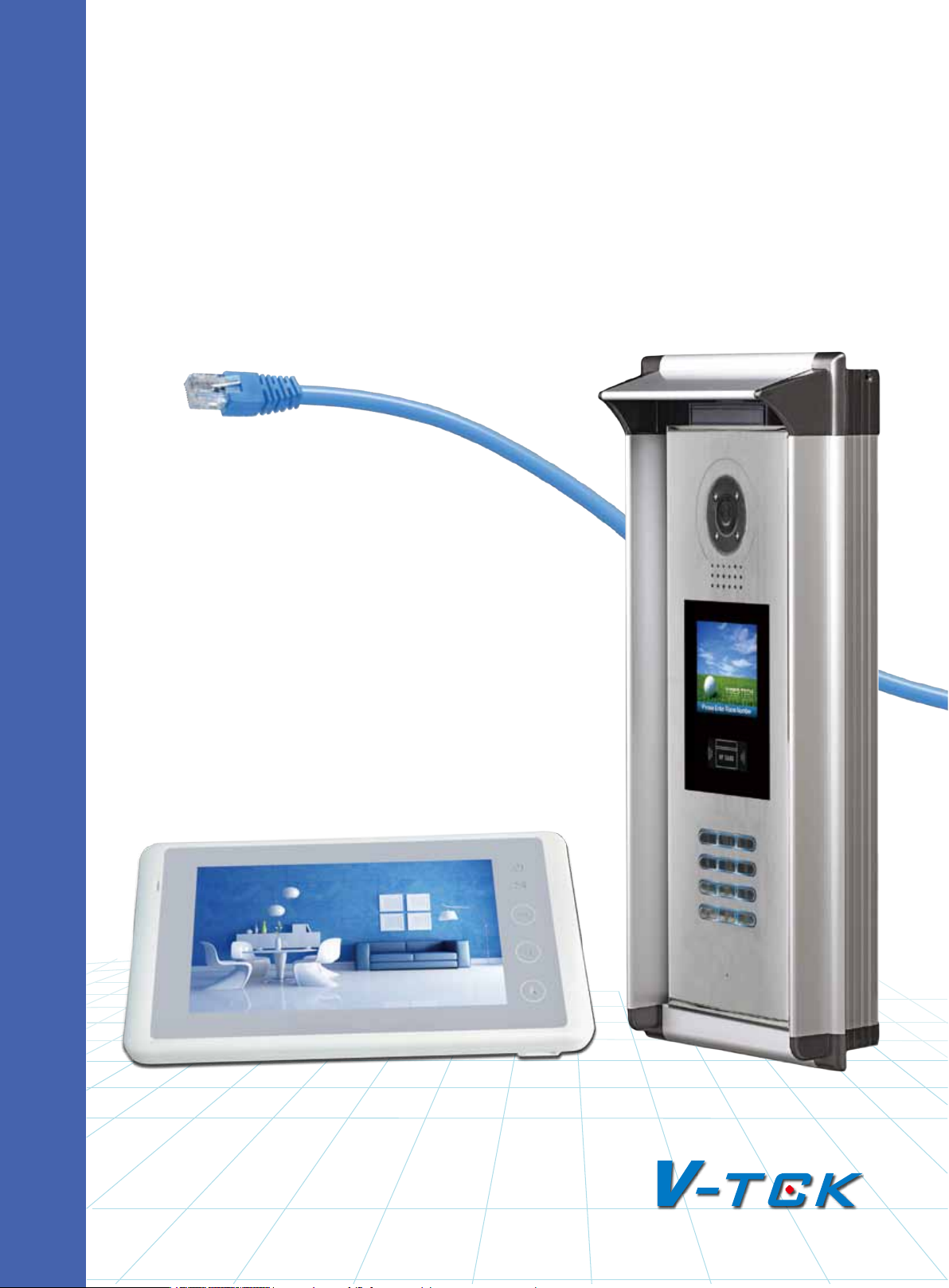
K5 SYSTEM
Technical guide 2012
Page 2
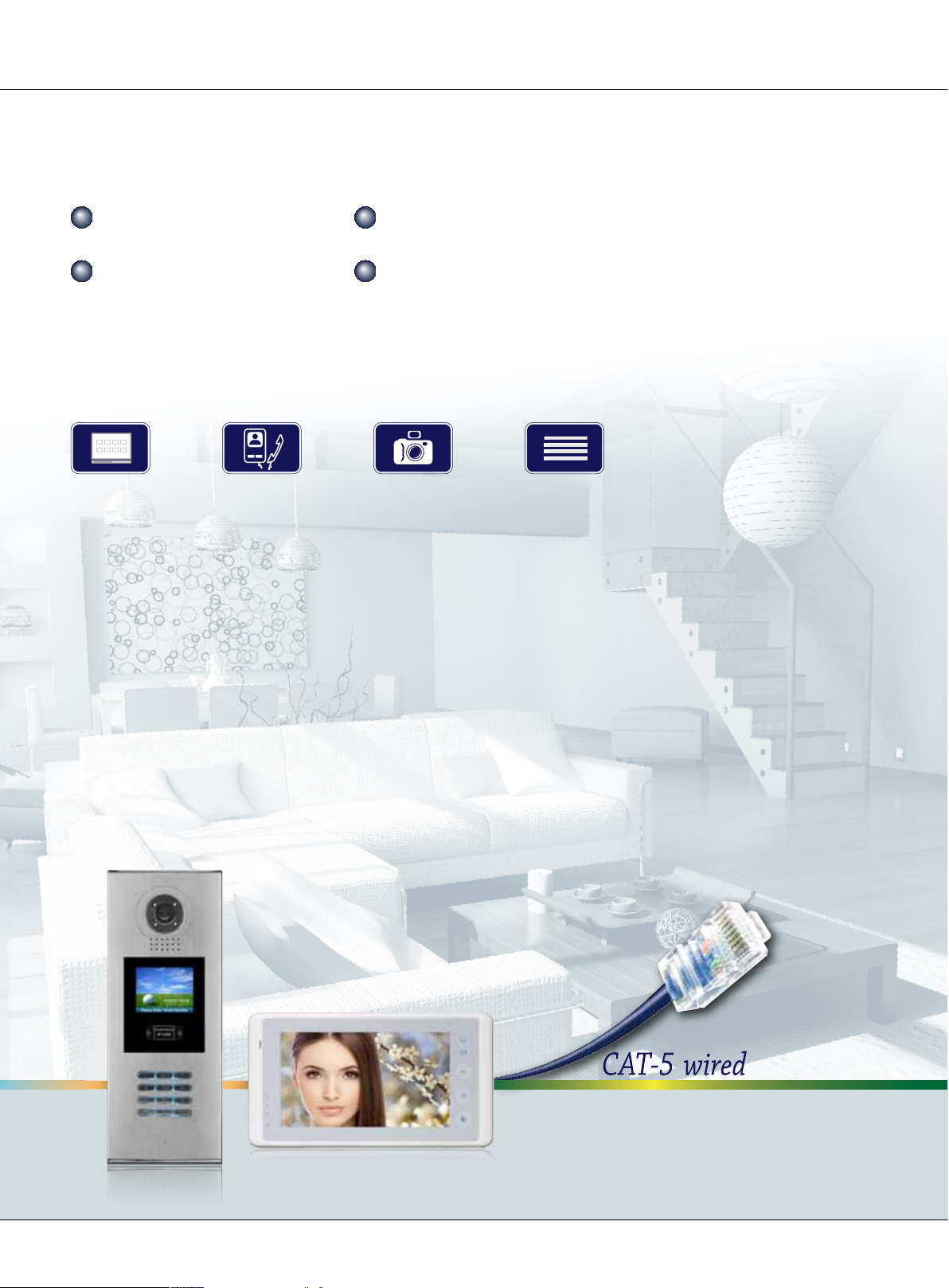
SYSTEM FEAGUTES
Large capacity Simple installation
Signal isolution
Debug online
PRODUCT FEAGUTES
Menu Guide Intercom Picture Memory Multi Channels
Page 2
K5 System Technical Guide
Page 3

Chapter 1: K5 System Overview ................................. 10
1.1 System Description .................................................11
1.2 System Features .....................................................12
1.3 System Applications ................................................13
Chapter 2: K5 System Parts .........................................14
2.1 Wiring Diagram ......................................................15
2.2 Product List ............................................................16
2.3 System Parts ..........................................................17
2.3.1 Outdoor Station: IP-MR18 .................................17
2.3.1.1 Features ...............................................17
2.3.1.2 Parts and Functions ...............................17
2.3.1.3 Terminal Description ..............................18
2.3.1.4 Door Station Functions ..........................19
2.3.1.5 Specications ........................................19
2.3.2 Indoor Monitor: C5-AT27 ..................................20
2.3.2.1 Features ...............................................20
2.3.2.2 Parts and Functions ...............................20
2.3.2.3 Terminal Description ..............................21
2.3.2.4 Indoor Monitor Functions .......................22
2.3.2.5 Specication .........................................22
2.3.3 Switchboard: IP-G21 ........................................23
2.3.3.1 Parts and Functions ...............................23
2.3.3.2 Terminal Description ..............................24
K5 System Technical Guide
Page 3
Page 4

Contents
2.3.4 Accessories .....................................................25
2.3.3.3 Specication .........................................25
2.3.4.1 C5-F4 ..................................................25
2.3.4.2 C5-F414 ...............................................26
2.3.4.3 C5-F422 ...............................................27
2.3.4.4 IP Converter: C5-IPC .............................28
2.3.4.5 Multi-Door station Switcher: C5-MDS .......29
2.3.4.6 Picture Memory Controller: C5-IMC ..........30
2.3.4.7 Independent Access Controller: GP-ACS ...31
2.3.4.8 Network Camera IP Converter: CM-IPC .....32
2.3.4.9 System Power Supply: PS5 .....................33
2.3.4.10 K5 System Cables ................................34
Chapter 3: K5 SYSTEM CONFIGURATION ..................... 35
3.1 One Entrance without Network ..................................36
3.1.1 Layout ...........................................................36
3.1.2 List of Accessories ...........................................36
3.2 Multi Entrances without Network ...............................37
3.2.1 Layout ...........................................................37
3.2.2 List of Accessories ...........................................37
3.3 One Entrance with Network ......................................38
3.3.1 Layout ...........................................................38
3.3.2 List of Accessories ...........................................38
3.4 Multi Entrances with Network ....................................39
Page 4
K5 System Technical Guide
Page 5

3.4.1 Layout ...........................................................39
3.4.2 List of Accessories ...........................................39
Chapter 4: K5 SYSTEM SETTINGS ................................ 40
4.1 Door station Setting ................................................41
4.1.1 Door station working mode ...............................41
4.1.2 IP-MR9L Conguration .....................................41
4.1.2.1 How to enter debug mode .....................41
4.1.2.2 Program Menu overview .........................42
4.1.2.3 Basic program settings ...........................43
4.1.2.4 Debug Tools ..........................................47
4.1.3 Conguration IP-MR18L ...................................49
4.1.3.1 How to enter debug mode .....................49
4.1.3.2 Program Menu overview .........................49
4.1.3.3 Basic program settings ...........................50
4.1.3.4 Debug Tools ..........................................56
4.2 Lock Connection .....................................................59
4.2.1 Lock Type .......................................................59
4.2.2 Connection Diagram .........................................59
4.2.2.1 Door Lock Controlled with Internal Power ..59
4.2.2.2 Door Lock Controlled with External Power .60
4.3 Monitor Setting .......................................................60
4.3.1 Concept of Address ..........................................60
4.3.2 Address setting on Monitor ...............................61
K5 System Technical Guide
Page 5
Page 6

Contents
4.3.3 Address Setting with door station ......................68
4.4 C5-IPC Setting........................................................70
4.4.1 Port Description ...............................................70
4.4.2 Settings .........................................................70
4.4.2.1 Level Switch setting ...............................70
4.4.2.2 DIP switch setting ..................................71
4.4.2.3 IP Address Setting .................................72
4.4.2.4 Parameters Settings ...............................75
4.4.2.5 Controller Concept .................................75
4.4.2.6 Examples: ............................................76
4.5 C5-MDS Setting ......................................................81
4.5.1 Port Description ...............................................81
4.5.2 Settings .........................................................81
4.5.2.1 Level Switch setting ...............................81
4.5.2.2 Address Setting .....................................81
4.5.2.3 The input number of C5-MDS ..................82
4.5.3 Connection Schematic ......................................83
4.6 Accessory Parts ......................................................84
4.6.1 Distributor ......................................................84
Page 6
4.6.1.1 Connection Schematic ............................84
4.6.1.2 Distributor Types ...................................86
4.6.1.3 Video Match ..........................................86
4.6.2 Picture-Memory-C5-IMC ...................................86
K5 System Technical Guide
Page 7

4.6.2.1 Connection Schematic ............................87
4.6.3 Access control-GP-ACS .....................................88
4.6.4 Camera control-CM-IPC ....................................89
Chapter 5: K5 SYSTEM SOFTWARES .............................90
5.1 PC Station Installation .............................................92
5.2 IP Address Setup ....................................................96
5.2.1 General Rules for IP Address Setup ....................96
5.2.2 IP Address Setup by IP8210-Cong ....................96
5.2.2.1 Set PC IP address ..................................96
5.2.2.2 Connect device to PC directly or network ..98
5.2.2.3 IP8210 Cong Software ..........................98
5.2.3 IP Address Setup by IP Device Software ........... 101
5.2.3.1 Set PC Station IP ................................. 101
5.2.3.2 Connect device to PC directly or network 101
5.2.3.3 Set IP Address ....................................102
5.3 IP Device 2012 ..................................................... 104
5.3.1 Introduction .................................................. 104
5.3.2 Login ...........................................................104
5.3.3 Project Property ............................................ 106
5.3.4 IP Node Cong ..............................................107
5.3.5 Block Cong .................................................110
5.3.6 Default project parameters .............................113
5.3.6.1 Guard center priority ............................ 114
K5 System Technical Guide
Page 7
Page 8

Contents
5.3.7 Management of Block C5-IPC ..........................117
5.3.8 Management of Common C5-IPC .....................123
5.3.6.2 Event up Setting ................................115
5.3.6.3 Input table ......................................... 115
5.3.6.4 IP Table .............................................. 116
5.3.7.1 Call Table ........................................... 117
5.3.7.2 Parameters Management ...................... 119
5.3.8.1 Call Table ........................................... 124
5.3.8.2 Parameters setting..............................124
5.3.8.3 Advanced .........................................124
5.3.9 Tip Device ....................................................125
5.4 IP Agent 2012 ......................................................126
5.4.1 Introduction .................................................. 126
5.4.2 Login ...........................................................126
5.4.3 Operate Interface .......................................... 127
5.4.4 Monitor Viewer .............................................. 128
5.4.4.1 Name & Function in Monitor Viewer ........128
5.4.4.2 Name & Function in Monitor Window ......129
5.4.4.3 Name & Function in Pop-up Call Window . 130
Page 8
5.4.4.4 Device List .......................................... 131
5.4.5 Record Viewer ...............................................135
5.4.5.1 Name & Function in Record Viewer ......... 135
5.4.5.2 Name & Function in The Record Window . 136
K5 System Technical Guide
Page 9

5.4.5.3 Record List ......................................... 136
5.4.6 Capture Viewer ............................................. 138
5.4.7 Setting .........................................................139
5.4.7.1 General .............................................. 139
5.4.7.2 Alarm Setting ...................................... 140
5.4.7.3 View & Layout ..................................... 142
5.4.7.4 Handset .............................................143
5.4.7.5 Security & Startup ...............................143
5.5 IP Access 2012 ..................................................... 144
5.5.1 Introduction .................................................. 144
5.5.2 Login ...........................................................144
5.5.3 Access Device Console ................................... 146
5.5.3.1 Cards information (Device) ...................146
5.5.3.2 Card Information (Database) ................146
5.5.3.3 Utilities .............................................. 147
5.5.3.4 Congure ...........................................148
5.5.4 Card Console ............................................... 150
5.5.4.1 Browse ..............................................150
5.5.4.2 Toolbar...............................................150
5.5.5 Pass Rule .....................................................153
5.5.6 Report .........................................................154
5.5.7 Report Card ..................................................154
5.5.8 Report Event ................................................. 154
K5 System Technical Guide
Page 9
Page 10

Chapter 1 K5 System Overview
Chapter 1
K5 System Overview
1.1 System Description ................................................................ 11
1.2 System Features .................................................................... 12
1.3 System Applications ............................................................... 13
Page 10
K5 System Technical Guide
Page 11
§§ 1.1§System§Descripon
The K5 system is the ideal system for simplifying installation in residential compounds with a high
number of users, developed with innovative technology, allows the installation of video intercom
systems up to 239 blocks and 512 users per block, applying CAT5 cable only except the power
supply to the system.
This system consists of six main components: outdoor station, indoor monitor, IP converter, distributor, power supply and other accessories. It is a security monitoring system that applies MCU
and TCP/IP LAN technologies.
K5 system is designed to perform not only common functions like making call, conversation,
monitoring, door lock release, network alarm and message to indoor monitor, but also other
advanced functions like lift control, public picture memory, by adding devices to the system,
and using the Switchboard(G21) or PC as the management and control centre for the whole system.
Based on standard CAT5 cable and RJ45 connector, K5 system has achieved significant breakthrough in such traditional bottleneck as SWS wiring, signal transmission wiring difculty, it makes
the installer’s job easier and faster by reducing the costs and process for projects and increasing
the anti-interference capacity as well. Furthermore, TCP/IP based networking makes the system
much more stable for big building community.
K5 System Technical Guide
Page 11
Page 12
Chapter 1 K5 System Overview
§§ 1.2§System§Features
• Max. 512 apartments per block
Network
Door/camera
Monitor
• Max.8 door stations per block
239 512
8
• Max 3 monitors in one at
• Max. 239 blocks in network
Per Block
• Max. 14 Switchboards per system(6 PC+8 IP-G21)
Signal separation technology:
•
With signal separation technology, each monitor has its own sig-
nal channel, to make sure that any malfunction on the monitor side won’t shutdown the system
Quick and easy installation for new and modernization projects:
•
Using the CAT5 cables for the
whole system, it will be possible to wire the cables through existing network without the need
for any masonry work to save the cost.
Long distance of signal transmission:
•
The system automatically equalizes and amplies the audio and video signal, restoring high quality performance even for long distances using CAT5
cable.
Audio and video signals are transmitted separately:
•
In this way, the system has better perform-
ance to avoid electronic disturbance.
Dierent congurations satisfy dierent requirements:
•
Using different distributors to meet dif-
ferent conversation requirements; and other extended devices make the system more powerful.
• Powerful management software: IP-AGENT. This software can replace IP-G21 to realize remote
control and management.
Quick and convenient maintenance:
•
Software will detect unavailable devices. Update can be
carried out online through LAN.
Page 12
K5 System Technical Guide
Page 13

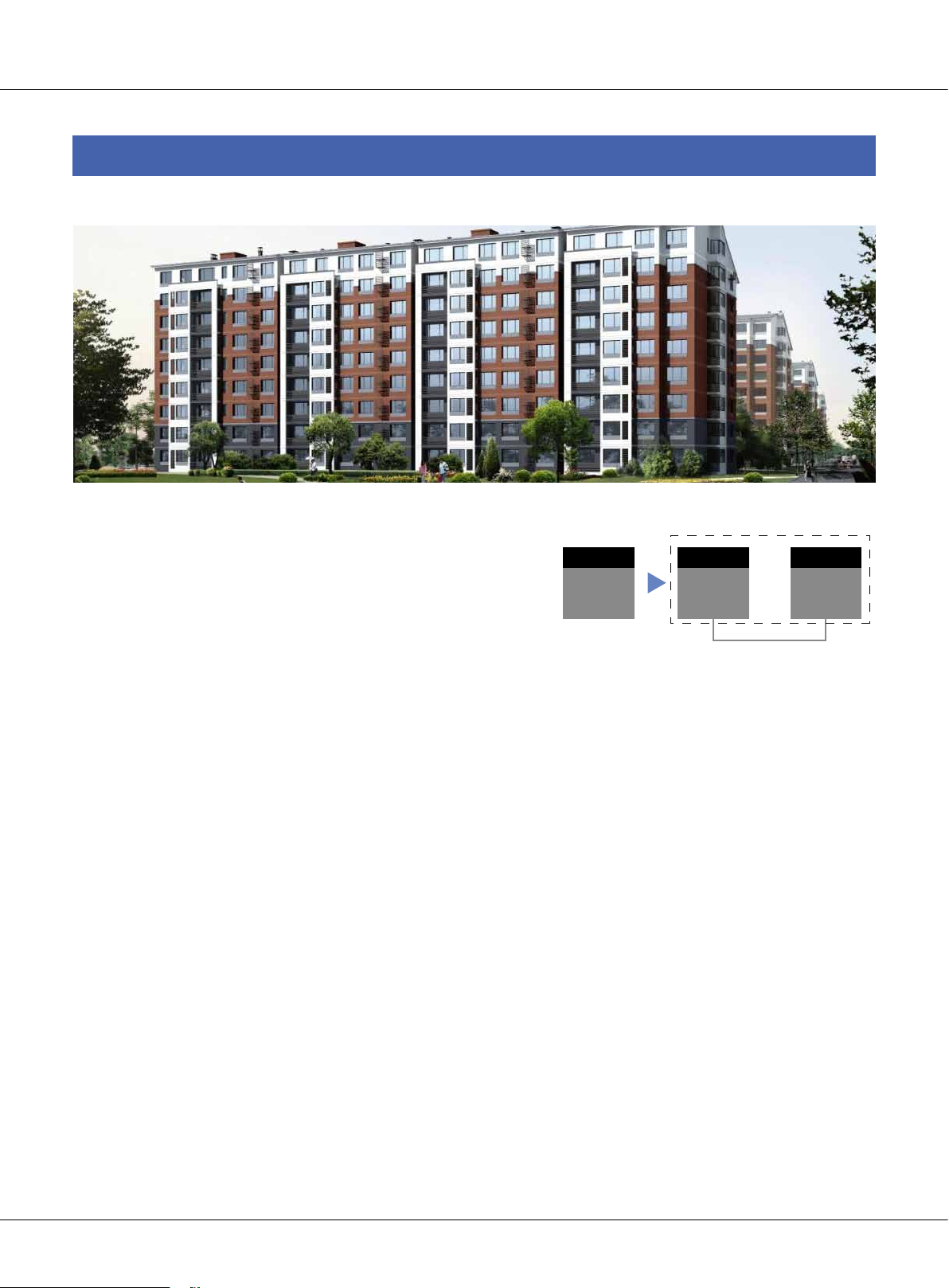
§§ 1.3§System§Applicaons
Large residential compound
One of the advanced features of K5 intercom system is that it supports 239 blocks in one system; it
can satisfy almost any size of residential compounds. Using a standard CAT5 network, each block
is able to accommodate hundreds of monitors and multiple outdoor stations. Each building may
have up to 8 outdoor stations. Max.14 Switchboards make management of community more convenient. And because of its smart operation and high efciency, the system can be easily operated
and maintained.
The system , being able to stop unknown individuals from getting inside multi entry buildings,
keep family safe from unwanted visitors without having to meet them at the door. If family is
away, missing a visitor is no longer an issue using this system with automatic recording capability.
In this system, conversation can be set up between two apartments just by two monitors. Detector-based Auto-alarm function ensures the security for the house owner.
Commercial building
Protect staff can safely conrm the identity of visitors before granting assess. And internal security
can control who enters secured rooms or oors of a building.
Educational security
The system keeps students safe while allowing parents and visitors a convenient way of requesting entry. Equipments, supplies, and records can be kept locked away while offering convenient
entry for students and staff.
Healthcare security
Call for immediate assistance when an emergency occurs. Secure sensitive areas within a building
and protect staff and assets.
K5 System Technical Guide
Page 13
Page 14

Chapter 2 K5 System Parts
Chapter 2
K5 System Parts
2.1 Wiring Diagram ...................................................................... 15
2.2 Product List ........................................................................... 16
2.3 System Parts ......................................................................... 17
2.3.1 Outdoor Station: IP-MR18 ............................................... 17
2.3.2 Indoor Monitor: C5-AT27 ................................................ 20
2.3.3 Switchboard: IP-G21 ...................................................... 23
2.3.4 Accessories ................................................................... 25
Page 14
K5 System Technical Guide
Page 15
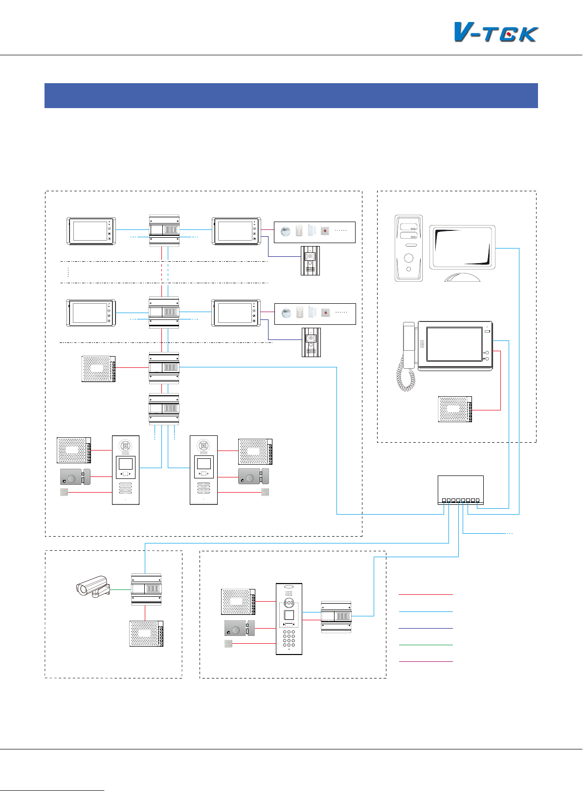
§§ 2.1§Wiring§Diagram
The below diagram demonstrates what the K5 system can do, by all the connecting different devices up.
Switchboard
1
2
3
4
Floor N
1
2
3
4
Floor 1
PS5
Exit Button
PS5
1 2 3
7 8 9
*
RF CARD
654
#0
C5-F414
C5-F414
Distributor
C5-IPC
C5-MDS
Unit Door Station
1
2
3
4
1
2
3
4
Indoor Monitor
IP Converter
Multi-Door Station Switch
RF CARD
1 2 3
654
7 8 9
#0
*
4 Alarm Zones
Secondary Door Station
IP-Agent
4 Alarm Zones
SOS
Switchboard: IP-G21
PS5
PS5
Network Switch
Exit Button
CM-IPC
IP Converter
PS5
Network Camera
PS5
Exit Button
Residential Building
C5-IPC
1 2 3
4 5 6
7 8 9
*
RF CARD
0 #
Common Door Station
K5 System Technical Guide
To Next Network
Switch or LAN/WAN
RVV 2*1.0
CAT5 Cable
RVVP 4*0.5
Coaxial-cable
RVV 2*1.0(for each zone)
Page 15
Page 16

Chapter 2 K5 System Parts
§§ 2.2§Product§List
Item Model Mounting Dimensions(mm)
DOOR STA-
TION
INDOOR
MONITOR
IP-MR18 Flush Mount 350*128*46 24V/95mA 24V/205mA
IP-MR9L Flush Mount 366*138*48 24V/85mA 24V/190mA
C5-AT16 Surface Mount 220*105*20 24V/87mA 24V/280mA
C5-AT25 Surface Mount 200*135*23 24V/15mA 24V/150mA
C5-AT27 Surface Mount 125*225*23 24V/40mA 24V/260mA
C5-F422 DIN Rail 140*150*60 24V/60mA 24V/120mA
C5-F414 DIN Rail 140*150*60 24V/60mA 24V/120mA
C5-F4 DIN Rail 88*140*32 24V/8mA 24V/80mA
C5-IPC DIN Rail 140*150*60 24V/185mA 24V/250mA
Consumption
Standby Working
ACCESSO-
RIES
C5-MDS DIN Rail 140*150*60 24V/50mA 24V/65mA
C5-IMC DIN Rail 140*150*60 20V/78mA 20V/135mA
GP-ACS DIN Rail 140*150*60 24V/45mA 24V/90mA
AC INPUT
PS5-24V DIN Rail 97*159*37
IP-G21 Surface Mount 203*303*32 16V/390mA 16V/850mA
100~120V/2.5A
200~240V/1.5A
DC OUTPUT
24V/4.5A
Page 16
K5 System Technical Guide
Page 17
§§ 2.3§System§Parts
ID Card Window
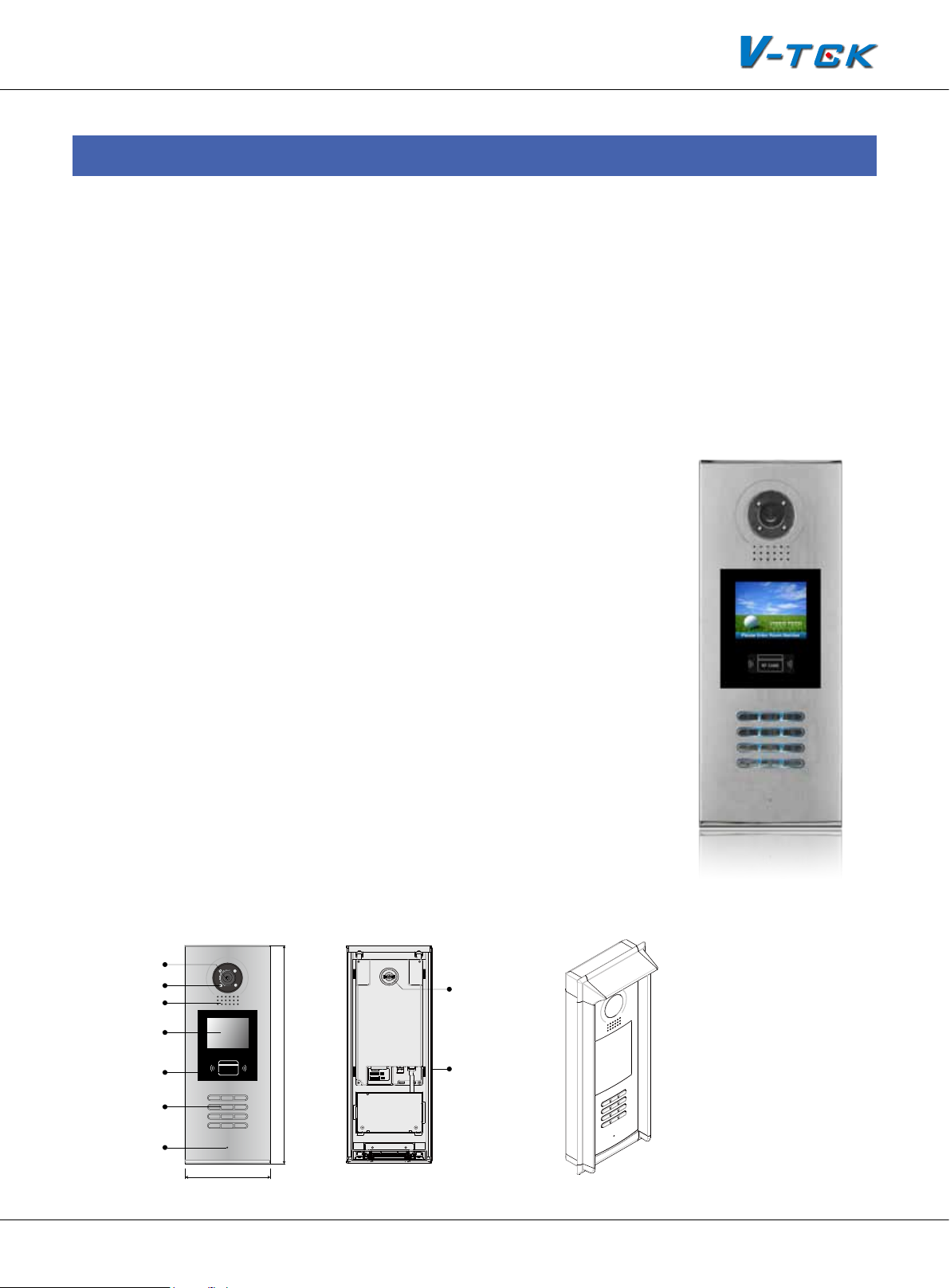
2.3.1§Outdoor§Staon:§IP-MR18
Full aluminum panel with luxurious and elegant appearance, design with 3.5” TFT color display for
versatile, innovative and high-performing communication.
2.3.1.1§Features
Functions such as monitoring, call, conversation and door lock release, etc
• Full anodize aluminum panel;
• CCD camera angle is adjustable;
• 3.5 inch LCD display to guide user operation;
• Access control ID/IC card function;
• The visitors can call indoor monitor and Switchboard;
• The keyboard is designed with automatic backlight;
• CCD super-brightness LED light compensation;
• Door lock release with ID/IC card or password;
• The parameters of door station can be set on itself;
• Volume adjustment;
• Direct connect to electronic lock of 12Vdc;
• Exit button can be connected;
• Change language and UI via SD card.
2.3.1.2§Parts§and§Funcons
Camera Lens
Night View LED
Speaker
LCD Screen
Digital Keypad
Microphone
RF CARD
1 2 3
7 8 9
*
128 mm
350 mm
12
3
654
#0
Adjustable Camera
Connectiong Port
With rainy cover
K5 System Technical Guide
Page 17
Page 18
Chapter 2 K5 System Parts
Camera Lens:
1.
Night View LED:
2.
Speaker:
3.
LCD Screen:
4.
Card Window:
5.
Digital Keypad:
6.
Microphone:
7.
Adjustable Camera:
8.
Connecting port:
9.
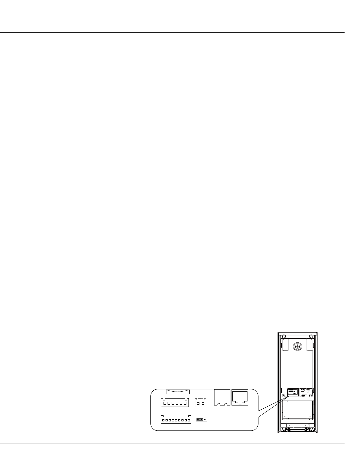
2.3.1.3§Terminal§Descripon
Capture images
Compensate light
Conversation between visitors and users
Show operational tips and others
Access control with ID/IC card
Making call and parameters setting
Conversation between visitors and users
Adjust the camera angle
Connect door station with other devices
+12V:
•
LK-(GND):
•
LK+ (COM):
•
NO.:
•
EB+:
•
EB-:
•
JP-LK:
•
T/R-:
•
T/R+:
•
JWP (P+, P-):
•
JWB (OUT):
•
SD Card Slot:
•
J/KMB:
•
12VDC power output
Normally open contact of the Relay (Can be set to be normally closed)
Exit button connection port. (Short EB+&EB- to unlock)
Exit button connection port
For electronic lock safety type setting (refer to Door Station Lock Connections)
USB-RS485 communication terminal negative
USB-RS485 communication terminal positive
Connect to keyboard on door station.
Power ground
Common contact of the Relay
Power input for door station
BUS Output (Including Data, audio and video signal)
Update language and UI of door station
Page 18
K5 System Technical Guide
SD Card Slot
CN-LK
EB+
EB-
N.O
LK+
LK-
+12V
J/KMB JP-LK
T/R- T/R+
3
12
CN1 CN2
12
3
Page 19

2.3.1.4§§Door§Staon§Funcons
Digital call by visitors
A visitor can input the resident’s room number to be shown on the display, As the signal transfer
to monitor, the resident can answer to communicate with visitor and release the lock. When necessary, the visitor or resident can dial 0000 to call Switchboard for help. While waiting or during
the conversation, the visitor can end conversation by pressing the * key, to end the call.
Resident monitoring
When the door station is standby, resident can press the monitor button to monitor door station
and see the image. In monitoring state, talk and unlock functions are still available. When several
outdoor stations are installed on the same building, resident can select the image they want to
view, or, view all the images one by one automatically.
Set as common door station
Common door station is for the whole resident community entrances. When visitor call resident,
block No. must be input at rst. Switchboard can call/monitor this door station while Indoor monitor cannot.
Open the locks by password or ID/IC card
As per the prompt on the display, we can input unlock password to open the door, and its format
is ‘#’ + ‘unlock password’, for example, if the password is 1111, you can input #1111 to unlock the
door. If the password input is not correct, the display will show “password error” and return to
standby after three short beeps. Then press on the # key and re-input the password. When using a
ID/IC card to release the lock, show the card in the front of the “RF CARD”, the lock will be released
after one long beep.
Support two types of lock connection
One type is Power-on-to-unlock (Normally open mode) connection, suitable for electrical lock.
Another is Power-off-to-unlock (Normally closed mode) connection, suitable for electromagnetic
lock.
2.3.1.5§Specicaons
Power supply: DC 24V
Camera Lens: 1/4 ACS 4T image sensor with DSP processor
Power consumption: Standby 2.5W; Working status 5W
Screen: 3.5 inch TFT
Resolution: 320(R, G, B)X240 pixels
Video signal: CCIR/EIA Optional
Wiring: Cat5
K5 System Technical Guide
Page 19
Page 20
Chapter 2 K5 System Parts
2.3.2§Indoor§Monitor:§C5-AT27
With 7” digital TFT touch screen and touch sensor button, this monitor is the best choice for modern intelligent life. Three different elegant appearances can satisfy different requirements.
2.3.2.1§Features
• 7 inch wide screen digital TFT LCD;
• Full touch screen and touch sensor button;
• Automatically record picture and max. 800 pieces color pictures memory optional;
• 8 areas alarm for house security which can warn Switchboard;
• Secondary door station connection;
• 2 slave monitors can be set with 1 master monitor;
• No additional power supply needed;
• Hands-free design with wall-mounting;
• Images and voice adjust by OSD menu;
• 12 different ring tones for selection;
• Automatically or manually monitor door station or camera;
• Read SMS from IP-Agent.
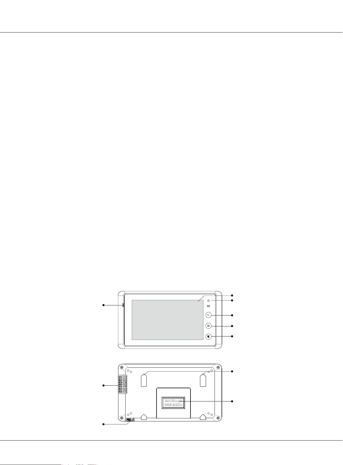
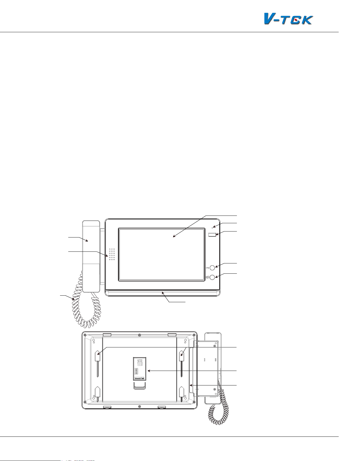
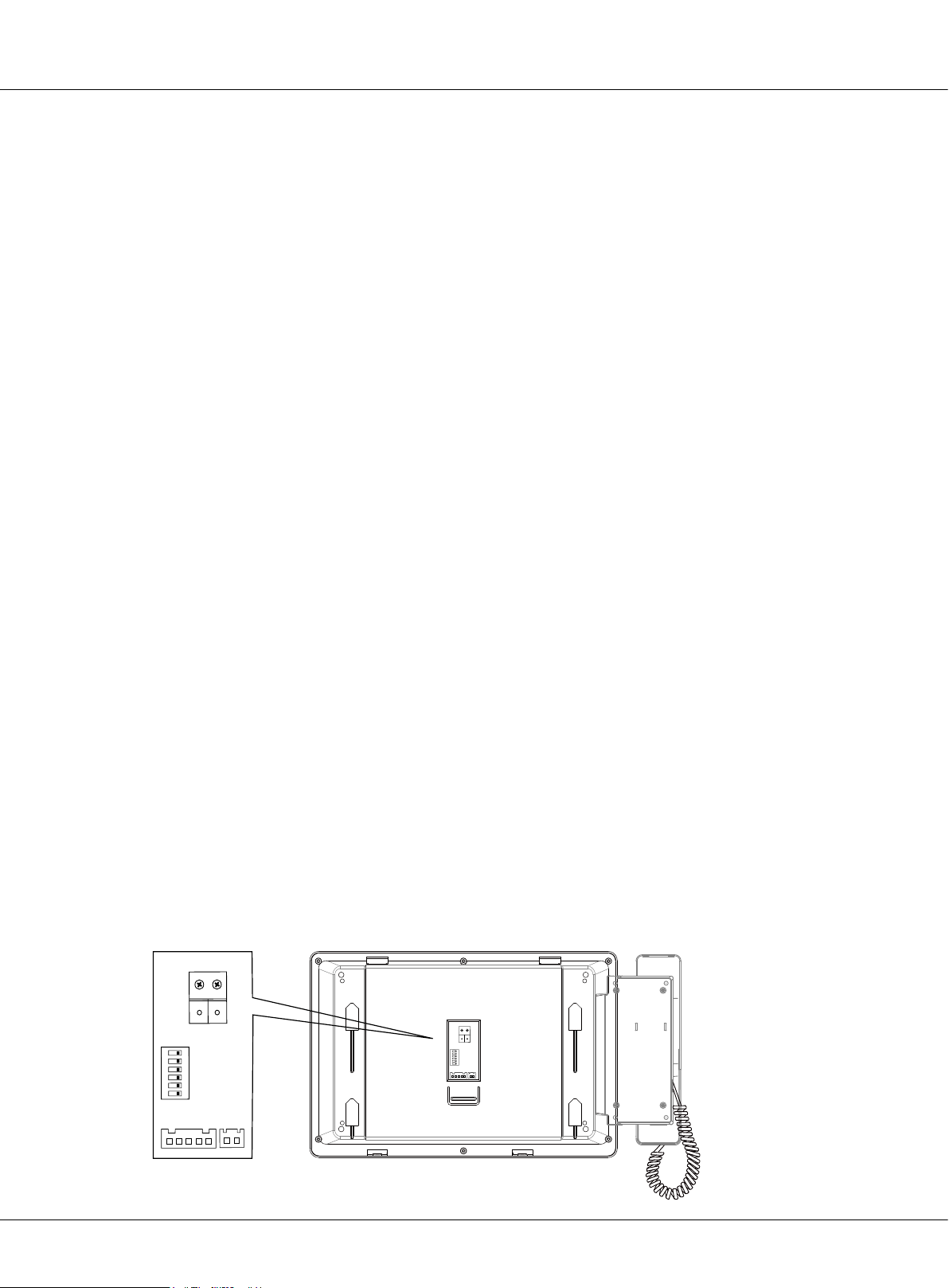
2.3.2.2§Parts§and§Funcons
Microphone
LCD Screen
LED Indicator
Unlock Key
Mon/Talk Key
Menu Key
Page 20
Mounting Hook
Speaker
Connection Port
SD Card Slot
K5 System Technical Guide
Page 21
LCD screen:
1.
LED indicator:
2.
Unlock key:
3.
Mon/Talk key:
4.
Display the images from outdoor station. Touch operation
Normally light on when in use
Press to release the door for visitors during talking or monitoring
Press to view the outside condition or to talk with the visitors while receiving a
call
Menu key:
5.
Microphone:
6.
Speaker:
7.
Mounting hook:
8.
Connection port:
9.
SD card slot:
10.
Press to open a list of operations available on the current screen
Send voice when talking
receives voice when talking
Used to hang up the monitor unit
Includes bus port, outdoor station port, alarm zone and 485 signal port
Use to insert SD card(for SD card model only)
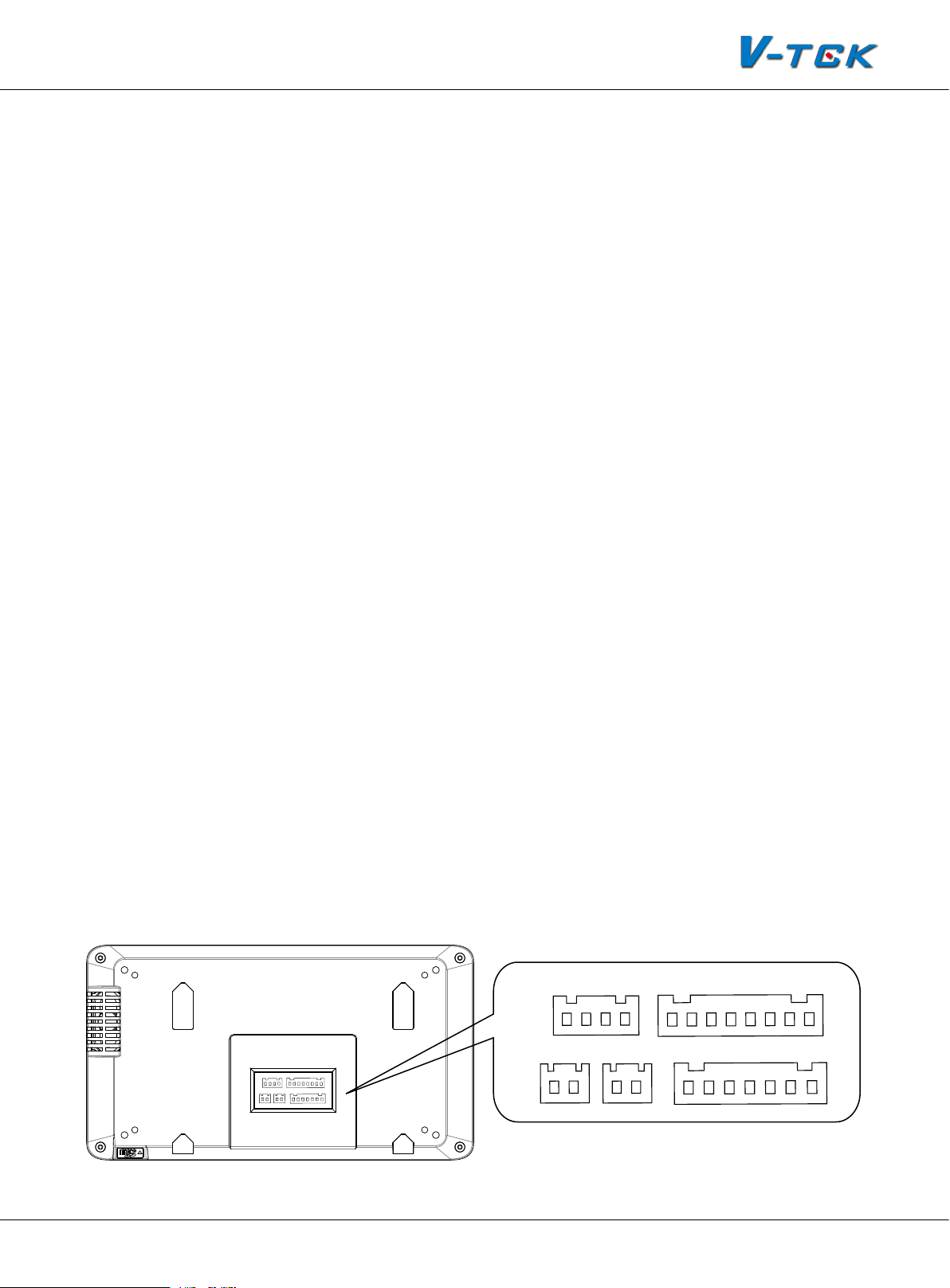
2.3.2.3§Terminal§Descripon
Outdoor station port
1R:
•
+12V power output for second door
station
2W:
•
•
•
Power ground
3Y:
Video signal from second door station
4B:
Audio signal from second door station
Bus port
FV+,FV- :
•
D1&D2:
•
AU:
•
Video signal input
Data input
Audio signal input
P+,P-:
•
GD,VD:
T/R-,T/R+:
Power input
Video matching
USB-RS485 communication termi-
nal for monitor update
Alarm Zone
Z1, Z2, Z3, Z4:
•
Connect to 4 zones alarm
for house security
COM:
•
•
Ground
PR:
Power output for sensor
FV+ FV- P- AU P- P+ P+D1&D2
3Y
4B
1R 2W
GD VD T/R+ T/R- Z1 Z2 Z3 Z4 COM COM PR
K5 System Technical Guide
Page 21
Page 22

Chapter 2 K5 System Parts
2.3.2.4§§Indoor§Monitor§Funcons
Receiving calls
Call from door station: When the monitor rings, it means a call is coming. The display will show the
video from the door station camera, press the answer button to accept the call and press the answer button again to end the call after nish the conversation Call from Switchboard: When handset rings, the display can show the video from the Switchboard camera(if the Switchboard is tted
with one camera). Press the answer button to accept the call and press the answer button again to
end the call after nish the conversation call from other monitor: The monitor will ring and show
the interface of intercom call. Two icon buttons will be shown on the screen for different operation: pick up or refuse.
Call other devices
Call Switchboard: While in standby, press the directly call Switchboard to call the Switchboard and
wait for it to answer the call. Press end button to end the conversation. The device will go back to
standby status. Call other monitor: Press intercom call to enter the intercom call interface, then input the room number to call other monitor.
Monitoring
While in standby, press the monitor button, the display will show the picture video of the door station. If there are several door stations, two ways of monitoring can be run: automatic and manual.
In automatic monitoring, the display will show all door stations’ pictures one by one; in manual
way, the display just show the picture which is selected. During monitoring, talk and unlock functions are available.
2.3.2.5§Specicaon
Power supply: DC 24V (supplied by system)
Power consumption: Standby 1W; Working status 5W
Monitor screen: 7 Inch color LCD
Display Resolutions: 800 x 480 pixels
Video signal: 1Vp-p, 75Ω, CCIR standard
Wiring : CAT5 cable, polarity
Dimension: 125(H) ×225(W) ×23(D) mm
Page 22
K5 System Technical Guide
Page 23
2.3.3§Switchboard:§IP-G21
IP-G21 is the advanced Switchboard for K5 system, designed as a dedicated switchboard to support K5 network system. Switchboard is an essential part in K5 system, it makes possible to manage calls from (to) Common Door Station or Door Station, and Indoor Monitor.
Additionally, IP-G21 has other functions, such as alarm receiver, depends on system conguration.
Max. 8 IP-G21 can be connected in system.
• 10 inch digital TFT with its resolution of 800x480 pixels
• Touch screen operation
• Handset or hands free answering
• Receive calling information from users
• Make intercom call to common door station, door station, and indoor monitor or other Switchboards
2.3.3.1§Parts§and§Funcons
LCD Screen
Microphone
Handset
SOS
Alarm Button
Speaker
Handset Line
Unlock Button
Call Button
LED Indicator
Mounting hook
L1
L2
DIPS
1 2 3 4 5 6
ON
RS485
GND
SW+
EXring
SW-
VD
Connection port
SD card slot
K5 System Technical Guide
Page 23
Page 24
Chapter 2 K5 System Parts
LCD screen:
1.
Microphone:
2.
Alarm Button:
3.
LED Indicator:
4.
indicator normally on when work in normal; (3) Blue indicator ash when in calling state; (4)
Red indicator ash when in talking state
Unlock Button:
5.
Call Button:
6.
Handset:
7.
Speaker:
8.
Handset Line:
9.
Mounting hook:
10.
Display the icon menu and images ,touch operation
Receives sound from the user
Blink when the guard unit receives alarm record
(1) Red indicator ash rst, green indicator ash later when power on; (2) Blue
Press to release the door for visitors during talking or monitoring
Press to activate the intercom function page
Pick up to talk with the visitors or users
Output sound from the visitors or users
Connect guard unit with handset.
Used to hang up the monitor unit
Connection port:
11.
SD card slot:
12.
Bus terminal
Use to insert SD card
2.3.3.2§Terminal§Descripon
L1,L2:
•
SW1:
•
SW+:
•
SW-:
•
Exring:
•
GND:
•
VD:
•
RS485:
•
Connect to the bus line
DIP switch
Reserve
Reserve
Buzzer connection port
Signal ground
Video signal connection port
USB-RS485 communication terminal
L2
L1
Page 24
DIPS
1 2 3 4 5 6
ON
RS485
SW+
SW-
EXring
GND
VD
K5 System Technical Guide
L1
L2
DIPS
1 2 3 4 5 6
ON
RS485
EXring
VD
GND
SW+
SW-
Page 25

2.3.3.3§Specicaon
Power input: DC 24V
Standby Current: 390mA
Working Current: 850mA
Screen: 10 inch digital TFT
Resolution: 800x480pixels
Video Signal: CCIR, 1Vp-p, 75Ω
Transmission Mode: TCP/IP
Connection Port: RJ45
Network Interface: Standard Ethernet interface
Working temperature: -10
0
C ~ +400C
Dimension: 382 *203 *32mm
2.3.4§Accessories
Using a signal cable, each apartment indoor monitor is connected to the BUS through distributor.
And one distributor can be connected to 4 indoor monitors. This device converts the BUS audio
and video signals and then distributes them to the connected indoor monitors.
There are three types of distributors: C5-F4, C5-F414 and C5-F422.
2.3.4.1§C5-F4
C5-F4 is a normal distributor. It just supports one audio and one video channel at the same time
while working.
Parts and Functions
P+, P-:
•
JWB (IN):
•
port includes audio, data & video. It can be
connected to last distributor or C5-IPC
JWB (OUT):
•
RJ45 port includes audio, data & video. It can
be connected to next distributor
Power input, DC 24V
Bus Signal Input. The port is a RJ45
Bus Signal Output. The port is a
C5-F4
IN-USE
LINKPOWER
PORT-A, PORT-B, PORT-C, PORT-D:
•
it can be connected to indoor monitors
VD-SET:
•
Setting for video matching
4 output,
P+ P- JWB(IN) JWB(OUT) PORT-A PORT-B PORT-C PORT-D
K5 System Technical Guide
Page 25
Page 26
Chapter 2 K5 System Parts
LINK:
•
•
•
Specications
Power supply: DC24V
Standby current: 8mA
Working current: 80mA
Working temperature: -10
Connection port: RJ45
Dimensions: 88*140*32mm
Signal indicator. Flicker means signal is transmitted in bus
Power:
IN-USE:
Power indicator. Always ON
Status Indicator. ON while working
0
C~400C
2.3.4.2§C5-F414
C5-F414 can support four audio and one video channels at the same time while working. It means
four conversations can take place at the same time. One of the conversations can be between
door station and monitor or Switchboard and monitor; other three are intercom calls. Signal separator is built inside to protect the system from shutting when one or some of the monitors gets
faulty, to guarantee each monitor in the system work independently.
Parts and Functions
P+, P-:
•
PA:
•
S1:
•
Power:
•
IN-USE:
•
LINK:
•
Power input, DC 24V
Test button
DIP Switch
Power indicator. Always ON
Status Indicator. ON while working
Signal indicator. Flicker means signal is
transmitted in bus
ERROR:
•
Error indication. ON when equipment
failure
RS485:
•
PC Port. Set parameters update the
rmware of C5-IPC by PC RS485-USB convertor
P+ P- PA
C5-F414
PORT-A
PORT-B PORT-C PORT-D JWB(IN) JWB(OUT)
S1
IN-USE LINK RS485
S1
P+
P-P+P-
PA
1ON2
PORT-A
PORT-B PORT-C PORT-D JWB(IN) JWB(OUT)
POWERERROR
ERROR
T/R-
INUSE
LINK
POWER
T/R+
VD-SET(L=HIGH)
VD-SET
JWB (IN):
•
Bus Signal Input. The port is a RJ45 port includes audio, data & video. It can be con-
nected to last distributor or C5-IPC
JWB (OUT):
•
Page 26
Bus Signal Output. The port is a RJ45 port includes audio, data & video. It can be
K5 System Technical Guide
Page 27
connected to next distributor
P+ P- PA
S1
PORT-A, PORT-B, PORT-C, PORT-D:
•
VD-SET:
•
Setting for video matching
4 output, it can be connected to indoor monitors
Specications
Power supply: DC24V
Standby current: 60mA
Working current: 120mA
Working temperature: -10
0
C~400C
Connection port: RJ45
Dimensions: 140*150*60mm
2.3.4.3§C5-F422
C5-F422 is a advanced distributor which can support two audio and video channels at the same
time. Two conversations with video are available at one system by using this device.
Parts and Functions
P+, P-:
•
PA:
•
S1:
•
Power:
•
IN-USE:
•
LINK:
•
Power input, DC 24V
Test button
DIP Switch
Power indicator. Always ON
Status Indicator. ON while working
Signal indicator. Flicker means signal
is transmitted in bus
ERROR:
•
Error indication. ON when equip-
ment failure
•
RS485:
PC Port. Set parameters update the
rmware of C5-IPC by PC RS485-USB convertor
JWB (IN):
•
Bus Signal Input. The port is a RJ45 port includes audio, data & video. It can be con-
nected to last distributor or C5-IPC
JWB (OUT):
•
Bus Signal Output. The port is a RJ45 port includes audio, data & video. It can be
connected to next distributor
IN-USE LINK RS485
S1
P+
P-P+P-
PA
ERROR
INUSE
1ON2
LINK
C5-F422
PORT-A PORT-B PORT-C PORT-D JWB(IN) JWB(OUT)
PORT-A
PORT-B PORT-C PORT-D JWB(IN) JWB(OUT)
POWERERROR
POWER
T/R-
T/R+
VD-SET(L=HIGH)
VD-SET
PORT-A, PORT-B, PORT-C, PORT-D:
•
VD-SET:
•
Setting for video matching
4 outputs, it can be connected to indoor monitors
K5 System Technical Guide
Page 27
Page 28

Chapter 2 K5 System Parts
Specications
Power supply: DC24V
Standby current: 60mA
Working current: 120mA
Working temperature: -10
Connection port: RJ45
Dimensions: 140*150*60mm
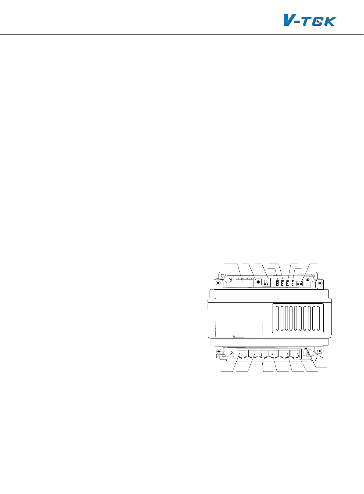
2.3.4.4§IP§Converter:§C5-IPC
C5-IPC is a network controller. It serves as system controller, manages all the data in the system
communication. To severs as a IP converter to effect the network connection.
• Built-in watchdog circuit in case of crash
0
C~400C
• LED Indicators to show system status
• RJ45 Standard connection port
• Talking volume adjustable
• Support TCP/IP network and ber transmission or broadband network access
• Adopt MPEG4 video protocol and G.729 audio protocol
• Include 100Mbit Ethernet LAN and RS485 connection port
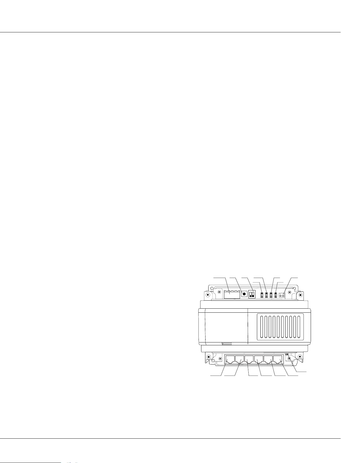
Parts and Functions
PA:
•
Reset. Press and hold PA for 3 seconds
to initialize C5-IPC; If initialization complete successfully, power off, and re-power
C5-IPC, LINK&IN-USE indicators will icker
JTAG S1 POWER PA VR600
S1
ON DIP
AG
1
2 3 4 5 6
POWER
LINK
IN-USE
once simultaneously, then INK indicator
will flicker till IN-USE indicator is always
ON
S1:
•
DIP Switch. Refer to DIP Switch Setting
C5-IPC
VR600
PA
+
IN-USELINK
JTAG:
•
PC Port. Update C5-IPC program by
PC that is connected by RS232 convertor
RS485:
•
PC Port. Set parameters update
the firmware of C5-IPC by PC RS485-USB
convertor
JWP:
•
•
Page 28
Power Input P+: Positive,24V; P-: Negative
JWB (IN):
Bus Signal Input. RJ45 port includes audio, data & video. It can be connected to door
K5 System Technical Guide
SW1
1 2
3
P+ P- P+ P- RS485
JWP
JWB(IN) JWB(OUT) CN(MDS) ETHERNET
RS-485 JWB(IN) CN-MDS
CN-NETJWB(OUT)SW1JP1/2/3
Page 29

station only
JWB (OUT):
•
Bus Signal Output. RJ45 port includes audio, data & video. It can be connected to
distributor.
CN-MDS:
•
CN-NET:
•
JP1/JP2/JP3:
•
SWI:
•
Bus Signal Input. RJ45 port, connected to MDS only
RJ45 Network Port, connected to LAN
Jumper. Removed if C5-MDS connected
Distributor Setting. Match different distributor
Specications
Power input: DC 24V
Standby Current: 185mA
Working Current: 250mA
Video Signal: CCIR, 1Vp-p, 75Ω
Audio Signal: 300~3,400 KHz, 0~240 mV
Transmission Mode: TCP/IP
Connection Port: RJ45
Network Interface: Standard Ethernet interface
Working temperature: -10
0
C ~ +400C
Dimension: 140*150*60 mm
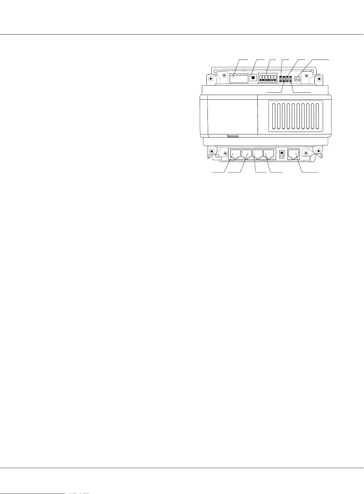
2.3.4.5§Mul-Door§staon§Switcher:§C5-MDS
C5-MDS is used when there are more than one door stations in one block. It serves as a door station switcher, to separate video and audio signal for each door station
• 4 door stations can be connected to 1 C5-MDS
• Max. 2 pieces of C5-MDS switchers per block
Parts and Functions
POWER:
•
LINK:
•
tion ERROR in bus.
Power indicator. Always ON while working.
Signal indicator. Flicker means signal is transmitted in bus, always ON means communica-
IN-USE:
•
ERROR:
•
JWB (OUT):
•
Status Indicator. ON while working.
Error indication. ON when equipment failure.
Output port. RJ45 port, connected to C5-IPC.
K5 System Technical Guide
Page 29
Page 30
Chapter 2 K5 System Parts
JWP:
•
Power input. P+, positive 24V; P-,
negative.
JWB (IN1, IN2, IN3, IN4):
•
Connected to
door stations (Max.4).
PA:
•
Test button. Press PA, the IN-USE
indicator will light, and then start to
monitor door station connected circular with click of relay.
S1:
•
DIP Switch function setting, refer to
DIP switch setting.
SW1:
•
•
Always set to the 2V, 2A position.
JTAG:
update port. Connected to PC to
update the rmware of C5-MDS
RS-485:
•
PC port. Used to update the rmware of C5-MDS.
Specication
JWP PA S1
P+
P-P+P-
PA
S1
ON DIP
1
ERROR
ERROR
2 3 4 5 6
IN-USE
C5-MDS
JWB(IN4)
JWB(IN3) JWB(IN2) JWB(IN1) JWB(OUT)
JWB(IN4) JWB(IN3) JWB(IN2) JWB(IN1)
INUSE
LINK
POWER
LINK
T/R-
T/R+
POWER
JWB(OUT)
RS-485
• Power input: DC 24V
• Standby Current: 50mA
• Working Current: 80mA
• Connection Port: RJ45
• Working temperature: -10
0
C ~ +400C
• Dimension: 140*150*60 mm
2.3.4.6§Picture§Memory§Controller:§C5-IMC
C5-ICM is independent picture memory controller for K5 system. When visitor call the monitor, the
C5-IMC will start to capture picture and save it, the resident can view the picture on the indoor
monitor.
• Picture playing is continuous and the switch time can be set by DIP switch
• Up to 800 pictures can be saved
Parts and functions
S201:
•
PA201:
•
PA202:
•
PA203:
•
Page 30
DIP switch
Capture picture in normal status, for DIP test in test status
Play picture in normal status, for EEPROM test in test status
Exit in normal status, for monitor communication in test status
K5 System Technical Guide
Page 31

PA204:
•
Reserved in normal status, for door
station communication in test status
LED201:
•
LED202:
•
LED203:
•
LED204:
•
JWP101:
•
RS485:
•
CN-NET:
•
Power indicator
Reserved
Picture saving indicator
Picture play indicator
Power input, DC 24V
PC port. To update the rmware
RJ45 Network Port, connected to
LAN
FM-SET:
•
Video match switch
Specication
• Power supply: DC24V
• Standby current: 78mA
S201
PA202 PA204
PA201
ON DIP
1
2 3 4 5 6
S201
PA203
PA201 PA202 PA203 PA204
LED202 LED203
LED201
C5-IMC
P+ T/R+
P-P+P-
JWP101 RS485 CN-NET FM-SET
T/R-
LED202
LED203
FM-SET
LED204LED201
LED204
• Working current: 135mA
• Working temperature: -10
0
C~400C
• Connection port: RJ45
• Dimensions: 140*150*60mm
2.3.4.7§Independent§Access§Controller:§GP-ACS
GP-ACS is an independent access controller, used for the entrance without the need for door station. Two locks and card readers can be connected to this device, so it can control two entrances
at the same time. GP-ACS can manage cards independently or through the PC in the network.
• Tow doors control ports (card reader port, electric lock port and status test)
• Lock release delay time setting
• Lock type setting
• Work status indicator
Parts and function
s
Power:
•
LINK:
•
IN-USE:
•
Power indicator, always ON while working
Signal indicator, icker means signal is transmitted in the bus line
Status indicator, ON while working
K5 System Technical Guide
Page 31
Page 32

Chapter 2 K5 System Parts
LED1:
•
reader
Indicators for rst group of card
JP-LK1 CN-DS1-1 CN-LK1
CN-DS1-2JP-LK2
CN-LK2
CN-RD1
CN-RD2 LED2
LED1 S1
LED2:
•
Indicators for second group of
card reader
JWP:
•
•
Power input, DC 24V
RS485:
PC port, to set the parameters
of GP-LIFT
CN-NET:
•
Signal input and output, RJ45
port, connected to C5-MDS
PA:
•
Test button, used for card manage-
ment without connecting to LAN
S1:
•
DIP switch
CN-RD1, CN-RD2:
•
Card reader connection port, connected to independent
card reader
CN-LK1, CN-LK2:
•
CN-DSI-1, CN-DSI-2:
•
Lock connection port, connected to lock and outlet button
Door status detection
• JP_LK1, JP_LK2: Lock jumper for lock type selection
JP-LK1
2
3
1
JP-LK2
2
3
1
SN-
SN+
EB+
EB-
N.O
LK+
LK-
+12V
BEEP
LED
WG1
GP-ACS
POWER LINK IN-USE
P-
P-
P+ A1 P- D1 D2 JWB(IN) JWB(OUT)
P+
POWER
JWP JWB
LINK IN-USE PA CN-NET
PA
RS485
ON DIP
LED1
1
2 3 4 5 6
LED2
S1
WG0
P-
+12V
RS485
Specication
• Power supply: DC24V
• Standby current: 50mA
• Working current: 90mA(not including reader)
• Working temperature: -10
0
C~400C
• Connection port: RJ45
• Dimensions: 140*150*60mm
2.3.4.8§Network§Camera§IP§Converter:§CM-IPC
CM-IPC is a device designed for Network camera. Through the CM-IPC, the computer can display
the video of the camera connected to the CM-IPC using the software IP-Agent.
• The IP-Agent can display the different cameras; the video can be sent to indoor monitors when
guard Ip-agent calls
Page 32
K5 System Technical Guide
Page 33

• Maximum 4 cameras can be connected to
the CM-IPC
Parts and functions
JWP:
•
•
Power input
JWV:
Video signal input
JW/VP:
•
Video signal input, connected to
VT-QSW
RS485:
•
LED203:
•
LED202:
•
K201:
•
SW201:
•
J701:
•
PC port. To update the rmware
Working indicator
Power indicator
Control the switch of QSW output
DIP switch
Signal output, RJ45 port, connected to LAN
Specication
• Power supply: DC24V
• Standby current: 78mA
• Working current: 135mA
• Working temperature : -10
0
C~400C
• Connection port: RJ45
CM-IPC
ON DIP
1
2 3 4
VG T/R+T/R-
P+P-VD
JWP JWV JW/VP K201 LED202 SW201 J701
RS485
LED203
• Dimensions: 140*150*60mm
2.3.4.9§System§Power§Supply:§PS5
The PS5 power supply unit is designed for K5 system to supply power for outdoor station, indoor
monitor and other accessories.
• Universal AC input/full range
• Multi protection: short circuit, overload, over voltage
• Cooling by free air convection
• DIN rail mounting
Parts and Functions
L (AC):
•
N (AC):
•
AC input
AC input
L (AC )
N (AC )
V-
VV+
V+
VADJ
LED
K5 System Technical Guide
Page 33
Page 34

Chapter 2 K5 System Parts
• : Earth Ground
V-:
•
DC power output, Negative (20~27 adjustable)
V+:
•
DC power output, Positive (20~27 adjustable)
VADJ:
•
LED:
•
Specication
• Input Voltage: AC 100~120V (2.5A), 200-240V (1.5A)
• Input Frequency: 50~60Hz
• Rated Voltage: DC 24V
• Rated Current: 4.5A
• Working temperature: -20
Output voltage adjustable
Working state indicator
0
C~600C
• Dimensions: 97*159*37mm
2.3.4.10§K5§System§Cables
Type Cable Specication Usage Remark
RVV2×1.0mm²
Bus
Lock RVV2×1.0mm² Lock connection From door station to lock
LAN CAT5 Digital signal Establish LAN or use existing LAN
CAT5
CAT5
Power cable for
distributor
Data , Audio and
Video bus
Data , Audio and Video
bus, Power line for in-
door monitor
From Door station to IP converter, IP
converter to distributor, and distributor
to distributor
From distributor to indoor monitor
Page 34
K5 System Technical Guide
Page 35

Chapter 3
K5 SYSTEM CONFIGURATION
3.1 One Entrance without Network ................................................. 36
3.1.1 Layout .......................................................................... 36
3.1.2 List of Accessories .......................................................... 36
3.2 Multi Entrances without Network .............................................. 37
3.2.1 Layout .......................................................................... 37
3.2.2 List of Accessories .......................................................... 37
3.3 One Entrance with Network ..................................................... 38
3.3.1 Layout .......................................................................... 38
3.3.2 List of Accessories .......................................................... 38
3.4 Multi Entrances with Network ................................................... 39
3.4.1 Layout .......................................................................... 39
3.4.2 List of Accessories .......................................................... 39
K5 System Technical Guide
Page 35
Page 36

Chapter 3 K5 System Conguration
The K5 system is exible to meet all kinds of need in different structure; installer can install the
system they want according to the requirements. Below are the examples with different combination of the system.
§§ 3.1§One§Entrance§without§Network
This is the most basic installation, it applies to buildings where there is only one entrance, without
network, so it can be connected without C5-IPC.
3.1.1§Layout
C5-F4
1
2
3
4
Floor N
1
2
3
4
Floor N
PS5
C5-F4
C5-F4
RF CARD
1 2 3
7 8 9
*
C5-F4
654
#0
1
2
3
4
1
2
3
4
Exit Button
RVV 2*1.0
CAT5 Cable
3.1.2§List§of§Accessories
Model Description
DS Outdoor station, call monitor and serves as controlling center in the system
Monitor User terminal, to communicate with door station or other monitors
Distributor To Separate Data, Audio, Video signal to each monitor, and power monitor
PS5 Adjustable DC power supply
Page 36
K5 System Technical Guide
Page 37

§§ 3.2§Mul§Entrances§without§Network
It applies to the installation where there is more than one entrance in the building, without network. All door stations can call any of the monitors in the building; monitors in the building can
view the door stations in turn or a specied door station.
3.2.1§Layout
C5-F414
PS5
Exit Button
1
2
3
4
Floor N
1
2
3
4
Floor 1
PS5
1 2 3
7 8 9
*
C5-F414
1
2
3
4
C5-F414
C5-F414
1
2
3
4
C5-IPC
C5-IPC
RVV 2*1.0
C5-MDS
C5-MDS
1 2 3
7 8 9
*
CAT5 Cable
PS5
RF CARD
654
#0
Exit Button
C5-MDS
C5-MDS
RF CARD
654
#0
3.2.2§List§of§Accessories
Model Description
DS Outdoor station, call monitor and unlock the door
Monitor User terminal, to communicate with door station or other monitors
Distributor To Separate Data, Audio, Video signal to each monitor, and give power to the monitor
PS5 Adjustable DC power supply
C5-IPC Controlling Center when there is C5-MDS
C5-MDS Multi-door station switcher, used to separate data, audio and video of dierent door stations
K5 System Technical Guide
Page 37
Page 38

Chapter 3 K5 System Conguration
§§ 3.3§One§Entrance§with§Network
Network connection is required when communication between different buildings or between
buildings and Switchboard. C5-IPC is needed to effect the network connection.
3.3.1§Layout
C5-F414
1
2
3
4
Floor N
1
2
3
4
Floor 1
PS5
C5-F414
C5-F414
C5-IPC
C5-F414
C5-IPC
1
2
3
4
1
2
3
4
To LAN/WAN
3.3.2§List§of§Accessories
Model Description
DS Outdoor station, call monitor and unlock the door
Monitor User terminal, to communicate with door station, other monitors and Switchboard
Distributor To separate data, audio, video signal to each monitor, and power monitor
PS5 Adjustable DC power supply
C5-IPC Controlling center and IP Converter
Page 38
K5 System Technical Guide
RF CARD
1 2 3
7 8 9
*
RVV 2*1.0
654
#0
Exit Button
CAT5 Cable
Page 39

§§ 3.4§Mul§Entrances§with§Network
It applies to the installation where there is more than one entrance in the building, with network.
All door stations can call any of the monitors in the building; monitors in the building can choose
to monitor all the door stations in turn or to select a specied door station. Also all door stations
will be able to communicate with the Switchboard.
3.4.1§Layout
C5-F22
PS5
Exit Button
1
2
3
4
Floor N
1
2
3
4
Floor 1
PS5
1 2 3
7 8 9
*
C5-F422
1
2
3
4
C5-F22
C5-F422
1
2
3
4
C5-IPC
C5-IPC
To LAN/WAN
RVV 2*1.0
C5-MDS
RF CARD
654
#0
C5-MDS
1 2 3
7 8 9
*
CAT5 Cable
PS5
RF CARD
654
#0
Exit Button
3.4.2§List§of§Accessories
Model Description
DS Outdoor station, call monitor and unlock the door
Monitor User terminal, to communicate without door station
Distributor To separate dada, audio, video signal to each monitor, and power monitor
PS5 Adjustable DC power supply
C5-MDS Multi-door station switcher, used to separate data, audio and video of dierent door stations
C5-IPC Controlling center and IP converter
K5 System Technical Guide
Page 39
Page 40

Chapter 4 K5 System Settings
Chapter 4
K5 SYSTEM SETTINGS
4.1 Door station Setting ............................................................... 41
4.1.1 Door station working mode ............................................. 41
4.1.2 IP-MR9L Conguration ................................................... 41
4.1.3 Conguration IP-MR18L ................................................. 49
4.2 Lock Connection .................................................................... 59
4.2.1 Lock Type ..................................................................... 59
4.2.2 Connection Diagram ....................................................... 59
4.3 Monitor Setting ...................................................................... 60
4.3.1 Concept of Address ........................................................ 60
4.3.2 Address setting on Monitor .............................................. 61
4.3.3 Address Setting with door station ..................................... 68
4.4 C5-IPC Setting ....................................................................... 70
4.4.1 Port Description ............................................................. 70
4.4.2 Settings ........................................................................ 70
4.5 C5-MDS Setting ..................................................................... 81
4.5.1 Port Description ............................................................. 81
4.5.2 Settings ........................................................................ 81
4.5.3 Connection Schematic .................................................... 83
4.6 Accessory Parts ..................................................................... 84
4.6.1 Distributor .................................................................... 84
4.6.2 Picture-Memory-C5-IMC .................................................. 86
4.6.3 Access control-GP-ACS ................................................... 88
4.6.4 Camera control-CM-IPC .................................................. 89
Page 40
K5 System Technical Guide
Page 41
§§ 4.1§Door§staon§Seng
V i de o En t r y S y s te m
- - - -- - - -- - - - - -- - - - - -- - - -- - -
- - - -- - - -- - - - - -- - - - - -- - - -- - -
> > D EB UG S TA T E <<
- - - -- - - -- - - - - -- - - - - -- - - -- - -
3 - # Mo ni to r P r og ra m
2 - # Se tu p
1 - # In st al l e r Se t u p
6 - # On li ne D e v ic e s . ..
E X I T: # -9 00 9
5 - # On li ne M o n it o r. . .
- - - -- - - -- - - - To ol s - -- - - - - -- -
4 - # Ca rd M a n a g e
V i de o En t r y S y s te m
[ **** ]
123
4
5
6
7
8
#
0
*
9
S y s te m R e ad y
V i de o En t r y S y s te m
S y s te m R e ad y
4.1.1§Door§staon§working§mode
Door station is to be installed in the entrance, to communicate with monitors or with Switchboard.
Door station can be set to work under two modes:
Unit door station
1.
To be installed on the entrance of each separate building, being able to call all the monitors inside
the building
Common door station
2.
To be installed on the common entrance, being able to call all the monitors inside the LAN network
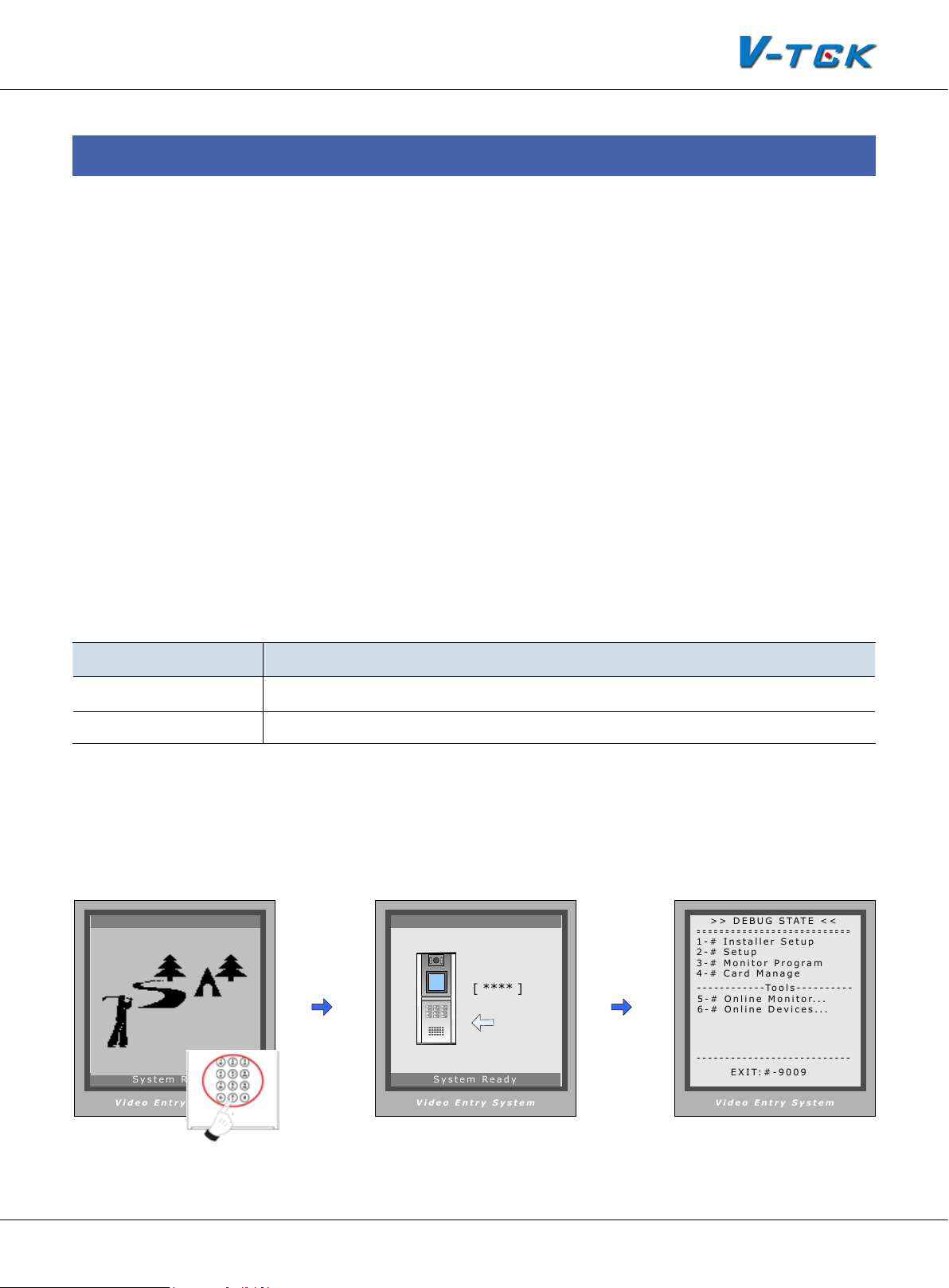
4.1.2§§IP-MR9L§Conguraon
Door stations can work in Normal mode and Debug mode. Normal mode is for daily function for
tenants; Debug mode is used for the installer, and debug tool can be activated under this mode.
Working Mode Function
Normal mode Daily use for tenants: calling, talking, unlocking
Debug mode Special mode for installer: quick access to all settings and debug tools
4.1.2.1§§How§to§enter§debug§mode
Door station is to be installed in the entrance, to communicate with monitors or with Switchboard.
Door station can be set to work under two modes:
When Door Station is
standby, press “#” key
Input “9008”, then input Admin
Code (“66666666” by default)
K5 System Technical Guide
Debug Mode menu is
launched
Page 41
Page 42
V i d e o E n tr y Sy s t e m
- - -- - - - - - - -- - -- - - - - - - -- - -- -
- - -- - - - - - - -- - -- - - - - - - -- - -- -
> > D EB UG S T A T E <<
- - -- - - - - - - -- - -- - - - - - - -- - -- -
3 - # Mo ni to r P ro gr am
2 - # Se tu p
1 - # In st al l er S et up
6 - # On li ne De vi ce s. . .
E X IT : #- 9 00 9
5 - # On li ne Mo ni to r. . .
- - -- - - - - - - --T o ol s - - - - - -- - --
4 - # Ca rd M a na ge
Chapter 4 K5 System Settings
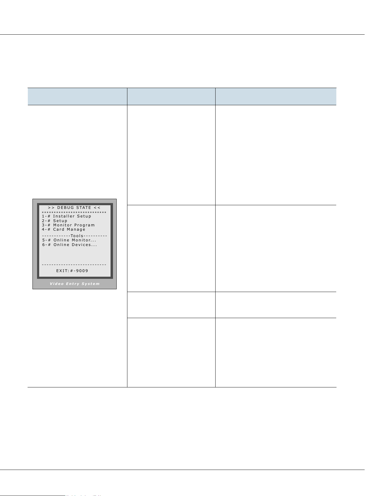
4.1.2.2§Program§Menu§overview
• Enter debug mode to over view all the menus and Tools
Debug State Menu Item Submenu
[1] Installer Setup
[1][1]. DS Serial NO.
[1][2]. Unlock Timing
[1][3]. Unlock Output
[1][4]. Card Memory
[1][5]. Doorplate Mode...
[1][6]. Audio Option...
[1][7]. Parameters...
[1][8]. Installer Code...
[1][9]. Default Set...
[2] Setup
[3] Monitor Program
[4] Card Manage
[2][1]. Language
[2][2]. Tone Select
[2][3]. Tone Volume
[2][4]. Unlock code
[2][5]. Code Check...
[2][6]. Clock...
[2][7]. Setup Code
[2][8]. About
[4][1]. Add Cards
[4][2]. Delete By Card
[4][3]. Delete By M.Code.
[4][4]. Cards Information
[4][5]. Format
Page 42
K5 System Technical Guide
Page 43

4.1.2.3§Basic§program§sengs
• Installer Setup (Debug State->1.Installer Setup)
Item Descriptions Factory Set
0 ---- Set as Unit door station. No C5-IPC connected. Set to 0,
then input 1/2/3 to select the related distributor type.
1. F411 ------> C5-F4
2. F414 ------> C5-F414
1. DS Serial NO.
3. F422 -------> C5-F422
1~8 --- Set as Unit door station. C5-IPC connected. Only one
door station connected: set to 1.When C5-MDS connected,
1st C5-MDS related to 1 -- 4
2nd C5-MDS related to 5 -- 8
9 ----- Set as Common door station
[0-11]
Standalone
Used with
F411
2. Unlock Timing
3. Unlock Output
4. Card Memory
5. Doorplate Mode
6. Audio Options…
7. Parameters The parameters will take eect only when there is no C5-IPC
To set the time that how long the door keeps open when
door is released. Ranging from 1 to 99 seconds.
To set the relay state for unlock, can be set to be normally
open or normally closed
To choose to use the memory of door station or that of C5IPC when access cards are in use
0- Store and read cards from the memory of Door station
1- Store and read cards from C5-IPC
To choose the input mode when you call monitor. It can
be set to from 1 to 8 digits. totally 8 numbers or 8 letters or
mixed are available
To set the audio match between door station and monitor
and that between door station and Switchboard, it can be
used when there is audio match problem such as noisy or
discontinuous voice.
[01]
[0]
Normally
open
[0]
Use memory
of DS for access
4 digits of
number
[0]
See
Parameters
8. Installer Code To change the Installer Code of door station [66666666]
To retrieve the original conguration of Door Station. Note
9. Default
this operation is an irreversible operation. Once restore is
done, the parameters including Installer Code and Setup
Code will return to Factory default setting
K5 System Technical Guide
Page 43
Page 44

Chapter 4 K5 System Settings
• Parameters(Debug State->1. Installer Setup->7. Parameters)
Three pages are available inside the parameters, press # to switch between different pages
Table 1
Item Descriptions Factory Set
1. Monitor Numbs
2. Monitor Timing To set the maximum monitoring time on door station [15]
3. Monitor & Talk Enble/Disable talk function when monitor is monitoring
4. Monitor & unlock Enble/Disable talk function when monitor is monitoring
5. Call Wait Time
6. Call Talk Time The maximum talking time between door station and monitors [60]
7. Intercom Time The maximum talking time between dierent monitors [90]
8. Call Ring Times How many times the door station ring when it makes a call [0]
9. Use # to call Whether to input # to call after entering the room number [0]
To set number of monitors that can monitor the door station at
the same time
The time that the door station keeps calling when no answer on
the monitor
Table 2
Item Descriptions Factory Set
[2]
[1]
Enable
[1]
Enable
[30]
To set the monitor coded 0099 as local Switchboard, so when
1. Local IM as GU
2. Multi IM Mode To set how multi-monitors in one apartment were coded [0]
3. Room Table Valid
4. Room Table Only To set how the door station calls the monitor
5. Unlock code 2
6. Unlock Code mode To choose to use common unlock mode or private unlock mode
7. Code Error Alarm Reserved
8. Code & Card Reserved
9. Code Disable Reserved
the user does ”Call Switchboard ” on the monitor, the call will be
transferred to the 0099 monitor
To use the room table to call the monitor when room table is
downloaded to the door station through ST-Cong
The second unlock code, valid only when the door station is set
to use common unlock code
[0]
Not
activated
[0]
Not
activated
None
[0]
Common
unlock
mode
Page 44
K5 System Technical Guide
Page 45

Table 3
Item Descriptions Factory Set
1. Display Mode Reserved [0]
2. Camera Power-on
3. Enable name list Enable/Disable namelist function [0]
4. Door Open Alarm reserved
5. Disable Intercom Enable/Disable intercom function between montiors [0]
6. Protect Setup Reserved
7. Open Card Mode Reserved
8. Support ST-NSW To choose to use with ST-NSW or C5-IPC
To choose to power the camera always or to power only when
door station is activated
[0]
Power
when
activated
[0]
Use with
C5-IPC
• Setup (Debug State->2. Setup)
Item Descriptions Factory Set
1. Language
2. Tone Select 12 calling tones are available [03]
3. Tone Volume Adjust the volume of calling tone [03]
4. Unlock Code The unlock code here serves as Unlock code 1 [1111]
5. Code Check…
6. Clock…
7. Setup code… To change the setup code of the Door station [88888888]
When Several languages are available, can be set to choose
dierent languages
To check the unlock code of each room code, when the door
station works under private unlock mode
To set the date and time of the door station that shows on
the screen display
[1]
English
Real time
8. About To show the information of the device
K5 System Technical Guide
Page 45
Page 46
V i de o En t r y S y s te m
- - - -- - - -- - - - - -- - - - - -- - - -- - -
- - - -- - - -- - - - - -- - - - - -- - - -- - -
> > D EB UG S TA T E <<
- - - -- - - -- - - - - -- - - - - -- - - -- - -
3 - # Mo ni to r P r og ra m
2 - # Se tu p
1 - # In st al l e r Se t u p
6 - # On li ne D e v ic e s . ..
E X I T: # -9 00 9
5 - # On li ne M o n it o r. . .
- - - -- - - -- - - - To ol s - -- - - - - -- -
4 - # Ca rd M a n a g e
V i de o En t r y S y s te m
- - - -- - - -- - - - - -- - - - - -- - - -- - -
- - - -- - - -- - - - - -- - - - - -- - - -- - -
[ 3 ]M on it or P r o gr am
- - - -- - - -- - - - - -- - - - - -- - - -- - -
N e w M. co de [- - - -]
O l d M. co de [ - - -- ]
* Ba ck
1 . Pr es s C a l l B u t t on
o f th e M o ni t o r
2 . In pu t n e w Co d e
W it hi n 1 0 S e c o nd s
3 . Pr es s # t o p r o g ra m
P r og ra mm in g St e p s:
V i de o En t r y S y s te m
- - - -- - - -- - - - - -- - - - - -- - - -- - -
- - - -- - - -- - - - - -- - - - - -- - - -- - -
[ 3 ]M on it or P r o gr am
- - - -- - - -- - - - - -- - - - - -- - - -- - -
N e w M. co de [0 0 0 2]
O l d M. co de [ 0 0 01 ]
* Ba ck
1 . Pr es s C a l l B u t t on
o f th e M o ni t o r
2 . In pu t n e w Co d e
W it hi n 1 0 S e c o nd s
3 . Pr es s # t o p r o g ra m
P r og ra mm in g St e p s:
V i de o En t r y S y s te m
> > [ 7] [ 1 ]
A d d Ca rd
- - - -
P l ea se I np u t M .C o d e
* B a ck
# S a ve
V i de o En t r y S y s te m
> > [ 7] [ 1 ]
A d d Ca rd
0 1 0 1
S h ow t he C a r d
* B a ck
# S a ve
V i de o En t r y S y s te m
> > [ 7] [ 1 ]
A d d Ca rd
0 1 0 1
C a r d: 1 5 97 7 1 3 1
* B a ck
# S a ve
Chapter 4 K5 System Settings
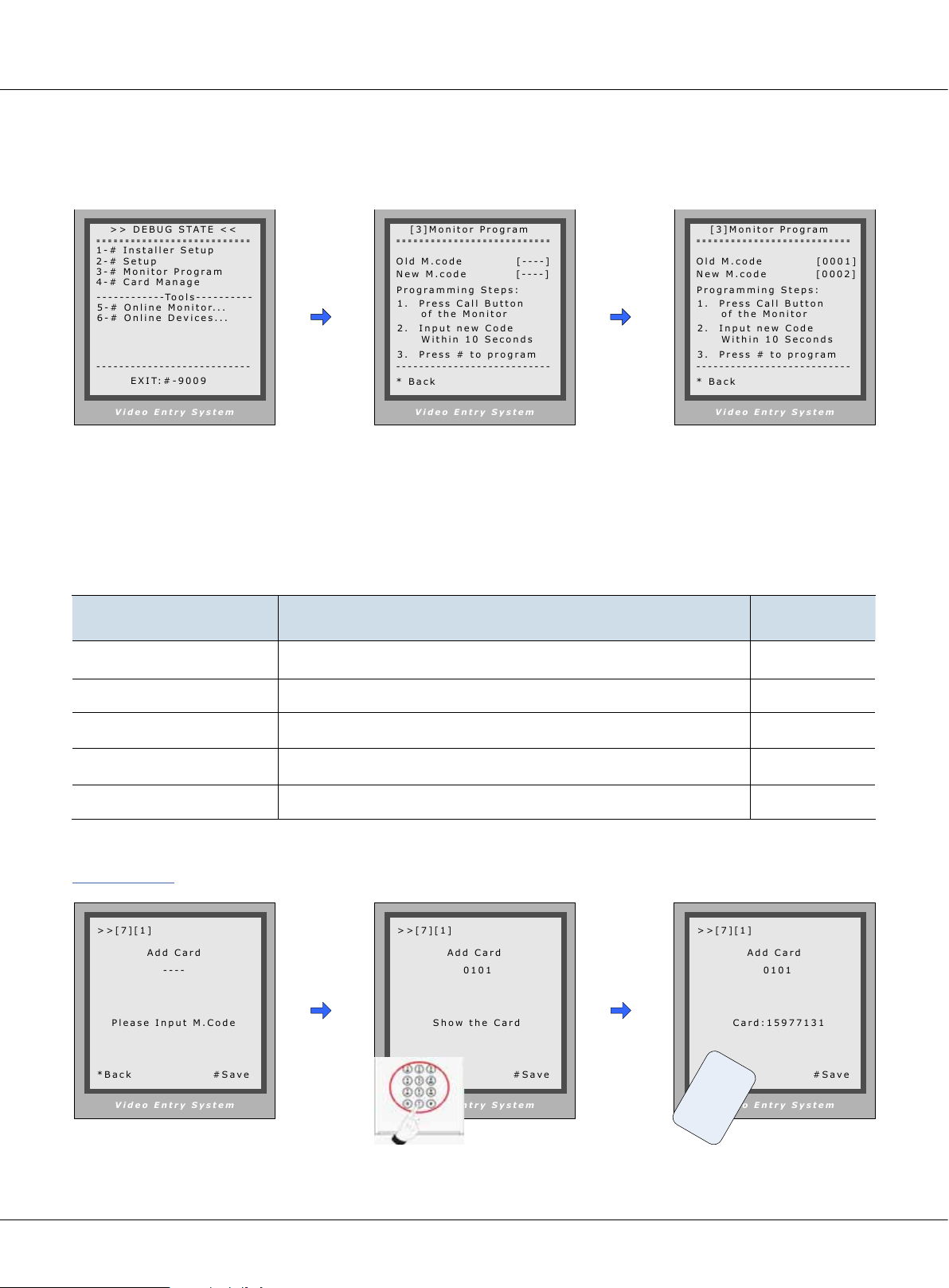
• Monitor Program (Debug State->3. Monitor Program).
Access Monitor Program in Debug Mode (Also See 1.1, Access Monitor program in normal mode
When in Debug Mode,
press “3#”
Monitor Program is
launched
Program the monitor according
to the instruction
• Card Management [Debug State->4. Card Management]
Item Descriptions Factory Set
1. Add Card Input the user code then swipe the card to be added NONE
2. Delete By Card Swipe the card to delete it NONE
3. Delete By M. Code To delete all the cards attached to the user code NONE
4. Cards information To show the amount of cards and counts NONE
5. Format To Delete all the card information saved on the door station
[1] Add Card
Enter Add Card menu, and
Room Code is asked.
Page 46
Input Room Code, then
press “#” Key.
K5 System Technical Guide
U p d at e d
r
e
d
r
s
a
U
C
Swipe the card to be added
Page 47
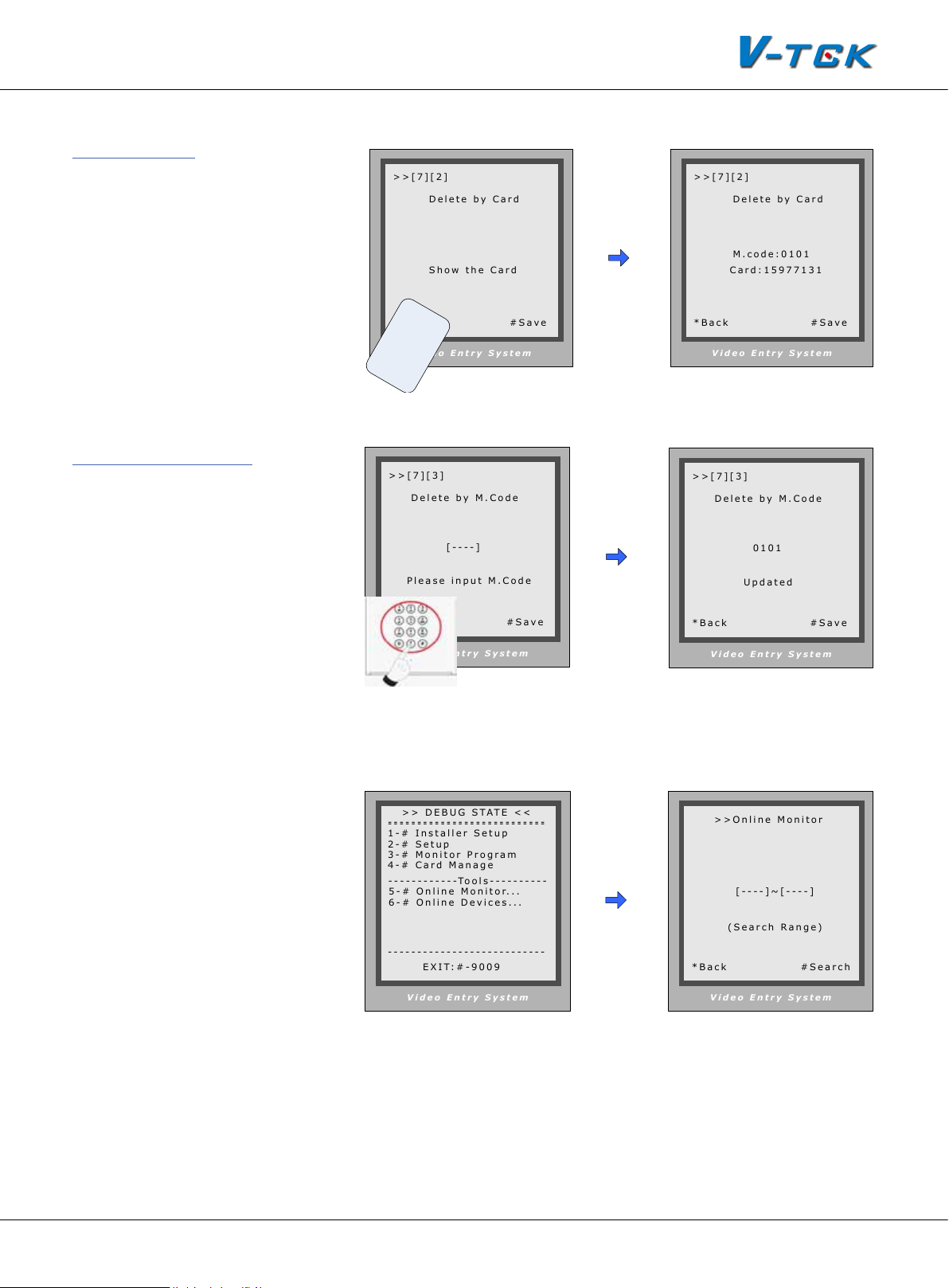
[2] Delete Card
V i de o En t r y S y s te m
> > [ 7 ] [ 2 ]
D e le te b y C a r d
* B a c k
# S a ve
S h ow t he C a r d
V i de o En t r y S y s te m
> > [ 7 ] [ 2 ]
M . c o d e : 0 1 0 1
C a r d : 1 5 9 7 7 1 31
* B a c k
# S a ve
D e le te b y C a r d
V i de o En t r y S y s te m
> > [ 7 ] [ 3]
D e le te b y M . C o d e
[ - - - - ]
* B a c k
# S a ve
P l ea se i np u t M. Co de
V i de o En t r y S y s te m
> > [ 7 ] [ 3]
D e le te b y M . C o d e
0 1 0 1
* B a c k
# S a ve
U p d a t e d
V i de o En t r y S y s te m
> > On li ne M o n i to r
[ - - - - ] ~[ -- - - ]
* B a c k
# S e a r c h
( S ea rc h Ra ng e)
V i de o En t r y S y s te m
- - - - - - -- -- - - - - - - - - - - - -- -- - -
- - - - - - -- -- - - - - - - - - - - - -- -- - -
> > D EB UG S TA T E <<
- - - - - - -- -- - - - - - - - - - - - -- -- - -
3 - # Mo ni to r P ro gr am
2 - # Se tu p
1 - # In st al l e r S et up
6 - # On li ne D e vi ce s. ..
E X I T: # -9 0 0 9
5 - # On li ne M o ni to r. . .
- - - - - - -- -- - -T o o l s - -- -- -- - - -
4 - # Ca rd M a n a ge
Enter
Delete by Card;
Swipe the card to be deleted,
and card number and Room
Code will be shown after deleted
[3] Delete by M. Code
Enter
Delete by M. Code;
Input the Room Code, press
“#” to confirm; all the cards
attached to the User code
will be deleted
U p d a t e d
r
e
d
r
s
a
U
C
4.1.2.4§Debug§Tools
• Entering debug tools
Note:
• Each Debug Option can be
activated or de-activated
separately
• Each Debug Command is a
sub-menu to execute and
show result.
• On Deb ug St ate menu,
the bottom line served as
displaying events, logs and
debug data.
Press #9008 then Installer
code to enter the Debug
mode.
Now input the code to
activate the corresponding tool
K5 System Technical Guide
For Example, Press 5#
to enter Online Monitor
search. Now enter the
starting user code and
ending user code and #
to start searching.
Page 47
Page 48

Chapter 4 K5 System Settings
1. Volume Adjust
Door station can adjust its talking volume by keypad. Note
that the volume adjusting function is automatically activated
in the Debug Mode.
Volume-Adjust
After
tor and enters talking state, current volume values are shown
on bottom line.
is activated, if Door Station calls a Moni-
2 0 - 0 8 0 6: 1 8
The left value means the
and the right value means the
station. Each value can be adjusted separately, ranges for 01
microphone volume
speaker volume
of door station,
of the door
[ 1 5] CONVERSATION [ 1 5 ]
V id e o E n t ry S y s t em
to 25, and 15 by default.
Note:
- For installations using hand free Monitors, it’s important that volume values in both
directions must be adjusted correctly. Otherwise, conversation maybe hard to hear, or
discontinuously, or feedback.
- The hand free conversation quality between Monitor and Door Station is related to
distance between them. On the back of hand free Monitor, a yellow rheostat (Variable
Resistor) serves as adjuster, to adapt to distance.
2. Auto –Dial back
The Auto-Dial-Back option is designed to simplify eld debugging, and to realize single person
testing. Also, it is always used to get a Monitor’s Room Code.
After Auto-Dial-Back is activated, by pressing Monitor’s Call Button, the Monitor’s Room Code is
shown at the Debug Message Area of screen. 3 seconds later, the Door Station will automatically
launch calling operation to the Monitor. However, if you don’t need calling, just press “*” when
Room Code is present. Please note: Auto-Dial-Back is automatically activated when you rst enter
Debug Mode, and Switchboard doesn’t response to Monitor’s calling request in this condition.
3. Online monitor
Function: Search the certain range of Monitor which is for checking the information of the online
monitor. After startup this operation, the Door Station search and display the present online monitor according to the setup range automatically.
4. Online Device
Door Station can search the devices on-line such as C5-MDS, C5-IPC, C5-IMC. The information will
be shown on the display after the searching.
Page 48
K5 System Technical Guide
Page 49

4.1.3§§Conguraon§IP-MR18L
[ **** ]
> > D eb u g S ta t e < <
1 - # To o l s
0 - # R e di a l
2 - # E x i t s
> > D eb u g St a te < <
1 - # T o o l s
0 - # R e d ia l
2 - # E xi ts
1 . I ns ta ll e r Se tu p
2 . S et up
3 . C ar d Me m or y
4 . O nl in e M on it or s
5 . O nl in e D ev ic es
Door stations also can work in Normal mode and Debug mode.
4.1.3.1§§How§to§enter§debug§mode
RF CARD
1 2 3
654
7 8 9
#0
*
Please Input Password
When Door Station is
standby, press “#” key
Input “9008”, then input Admin
Code (“66666666” by default)
4.1.3.2§Program§Menu§overview
• Enter debug mode to over view all the menus and Tools
Debug State Menu Item Submenu
[1] Installer Setup
[2] Setup
Tools
*Back
[3] Card Manage
[4] Online Monitors
[5] Online Devices
Debug Mode menu is
launched
[1][1]. ID Code
[1][2]. Unlock Timing
[1][3]. Unlock Output
[1][4]. Card Memory
[1][5]. Doorplate Mode...
[1][6]. Audio Option...
[1][7]. Parameters...
[1][8]. Installer Code...
[1][9]. Default Set...
[2][1]. Language
[2][2]. Tone Select
[2][3]. Tone Volume
[2][4]. Unlock code
[2][5]. Display Mode
[2][6]. Clock...
[2][7]. Setup Code...
[2][8]. About...
[2][9]. Default...
[3][1]. Add Card...
[3][2]. Delete by Card
[3][3]. Delete by M.Code
[3][4]. Cards Information
[3][5]. Format
K5 System Technical Guide
Page 49
Page 50

Chapter 4 K5 System Settings
4.1.3.3§Basic§program§sengs
• Installer Setup (Debug State->1#->1.Installer Setup)
Item Descriptions Factory Set
1.When there is only one door station and no C5-IPC, set to 0.
And set the type of distributor used with it. When C5-IPC is
1. ID Code.
connected, must not be set to 0.
2. When C5-MDS is connected, be set to from 1~8 according
to which port it is connected on the C5-MDS
3. When used as common door station, set to 9
[0-11]
Standalone
Used with
F411
2. Unlock Timing
3. Unlock Output
4. Card Memory
5. Doorplate Mode
6. Audio Options…
To set the time that how long the door keeps open when
door is released. Ranging from 1 to 99 seconds.
To set the relay state for unlock, can be set to be normally
open or normally closed
To choose to use the memory of door station or that of C5IPC when access cards are in use
0-Use memory of DS for access
1-Use C5-IPC for access
1. To choose the input mode when you call monitor. It can
be set to from 1 to 8 digits. totally 8 numbers or 8 letters or
mixed are available
2. Set to 0 to activate call directly after entering the number;
Set to 1 to activate the call by # following the number
To set the audio match between door station and monitor
and that between door station and Switchboard, it can be
used when there is audio match problem such as feedback
or discontinuous voice
[01]
[0]
Normally
open
[0]
Use memory
of DS for access
[0]
4 digits of
number
[0]
7. Parameters The preset parameters when ID Code is set to 0.
8. Installer Code To change the Installer Code of door station [66666666]
To retrieve the original conguration of Door Station. Note
9. Default
Page 50
K5 System Technical Guide
this operation is an irreversible operation. Once restore is
done, the parameters including Installer Code and Setup
Code will return to Factory default
See
Parameters
Page 51

• Installer Setup (Debug State->1#->1. Installer Setup->7. Parameters)
Three pages are available inside the parameters, press # to switch between different pages
Table 1
Item Descriptions Factory Set
1. Monitor Numbs
2. Monitor Timing The maximum monitoring time [30]
3. Monitor & Talk Enable/Disable talk function when monitoring
4. Monitor & unlock Enable/Disable unlock function when monitoring
5.Wait Timing Maximum wait time when making a call [30]
6. Talk Timing Maximum talk time available in a call [90]
To set number of monitors that can monitor the door station
at the same time
Table 2
Item Descriptions Factory Set
To set the monitor coded 0099 as local Switchboard, so when
1. Ring Numbers
the user does ”Call Switchboard ” on the monitor, the call will be
transferred to the 0099 monitor
[2]
[1]:
Enable
[1]:
Enable
[0]
Not
activated
2. Name List Mode Reserved
To set the monitor coded 0099 as local Switchboard, so when
3. Local IM as GU
4. Multi IM Mode
5. Room Table Valid
6. Room Table Only Reserved
the user does ”Call Switchboard ” on the monitor, the call will be
transferred to the 0099 monitor
To set the code rule when there are extended monitors in the
one apartment
To use the room table to call the monitor when room table is
downloaded to the door station through ST-Cong
K5 System Technical Guide
[0]
Not
activated
[0]
Default
rule
[0]
Not
activated
Page 51
Page 52

Chapter 4 K5 System Settings
Table 3
Item Descriptions Factory Set
1. Unlock Code 2 Reserved None
2. Unlock Code Mode Reserved [0]
3. Camera Power-on
4. Reserved Reserved
To choose to power the camera always or to power only when
door station is activated
[0]
Power
when
activated
5. Disable Intercom Disable/Enable intercom function between monitors
• Setup (Debug State->1#->2. Setup)
Item Descriptions Factory Set
1. Language To choose dierent languages via SD Card
2. Tone Select 12 calling tones are available [03]
3. Tone Volume Adjust the volume of calling tone [03]
4. Unlock Code To change the unlock code [1111]
5. Display Mode
Choose to show / not to show the view of visitor when door
station is making a call
[0]
Enable
[01]
English
[0] show
6. Clock…
7. Setup code… To change the setup code of the Door station [88888888]
8. About To show the information of the device
Page 52
K5 System Technical Guide
To set the date and time of the door station that shows on
the screen display
Real time
Page 53

• Unlock by code(Debug State->1#->1. Installer Setup->7. Parameters)
[ **** ]
4 . U nl oc k C o d e [1 1 1 1 ]
[ **** ]
1 . L an gu ag e [ 1 ]
2 . T o n e Se le c t [ 03 ]
3 . T o n e Vo l um e [ 0 3]
5 . D is pl ay M o d e
6 . C lo ck
7 . S et up C o d e
8 . A bo ut
9 . D ef au lt
4 . U nl oc k Co de [ 1 1 1 1]
RF CARD
1 2 3
654
7 8 9
#0
*
RF CARD
i
Door Open
1 2 3
654
7 8 9
#0
*
Please Input Password
When Door Station is
standby, press “#” key
Input 4 digits Unlock Code
If verified correctly,
door open
• Unlock code setting (Debug State->1#->2. Setup->4. Unlock code)
If Door Station runs as Debug State, you can press “1#” then “2 “to enter Setup to make congure
unlock setting;
However, if runs as Normal State, follow these steps to enter:
Setup
RF CARD
1 2 3
654
7 8 9
#0
*
Press No.
to select
[ - - - - ]
( * * * *)
Please Input Password
Press “#” key, Input “8002”,
then input Setup Code or
*Back
Press “4” to enter unlock
code item.
*Back
Input 4 digits number,
then press “#” to update
# Save
Admin Code (88888888 or
66666666 by default)
• Proximity Cards operation
This part explains how to configure the Proximity card access function, by means of keypad.
Please note, to a Door Station without access security, all the related parameters can’t be updated.
The capacity for cards in IP-MR6L/IP-MR9L is 1000. If door station is used with C5-IPC, cards can
be stored in C5-IPC ,the memory of C5-IPC can be upgraded to 10,000 cards if needed. It is much
convenient to manage access security and cards by means of IP-Device software in a networked
system. Reading distance is approximately 30mm from the window.There are 2 type of setup, for
Access controller and cards authorization.
Door Station should enter Debug State rst, and then operate as below:
K5 System Technical Guide
Page 53
Page 54

1 . ID C od e [ 0- 11 ]
2 . Un lo ck T im i n g [ 01 ]
3 . Un lo ck O u t p ut [0 ]
4 . Ca rd M em o r y [ 0]
5 . Do or pl at e M o d e [0 ]
6 . Au di o Op t i o n s . . .
7 . Pa r am et e r s . ..
9 . D e f a ul t. . .
8 . In st al le r C od e. ..
2 . S et up
4 . O nl in e M o n it or s
5 . O nl in e D e v ic es
1 . I ns ta ll e r Se tu p
3 . C ar d Me m o r y
1 . Ad d Ca rd . . .
2 . De le te B y C a r d
3 . De le te B y M .c od e
4 . Ca rd I nf o r m at io n
5 . F o rm at
Chapter 4 K5 System Settings
Tools
*Back
Installer
Setup
Press1~9
to select
*Back
Card
Memory
Press No.
to select
*Back
About access Memory
• The access cards can be saved in the door station ,for this , the Card memory in Installer setup,
Must be set to 0(It is 0 by default)
• The access cards also can be saved in the C5-IPC connected with the door station. For this, the
Card memory in Installer setup should be set to 1.
About cards
• User Cards are associated with Room Code; an authorized User Card can open the door at any
time.
• Manage Card is restricted to pre-dened access rule, and hold by visitor or service person.
• Please note, Manage Cards can only be saved in C5-IPC and authorized by means of IP-Access
software.
• To authorize cards, enter Card Management rst (refer Chapter 6.1 to), then select the item.
• Please note that the following operations are irreversible.
Page 54
K5 System Technical Guide
Page 55

1 . A dd Ca rd . . .
1 . A dd Ca rd . . .
1 . A dd Ca rd . . .
[1] Add User Card
2 . D el et e B y C ar d . ..
2 . D el et e B y C ar d . ..
3 . D el et e B y M .c o d e
3 . D el et e B y M .c o d e
4 . C ar ds I n f o r ma t i o n
[----]
Please Input Room Code
* Back # Save
Enter Add Card menu,
and Room Code is asked.
[2] Delete User Card
- Delete by reading card
Enter
Delete by Card
Read the card to be deleted,
and card num ber will be
shown on the display
[0101] [0101]
Show The Card
* Back # Save
* Back
e
s
U
C
r
a
C a r d numbs :
d
r
1 5 9 77 1 3 1
Show The Card
Input Room Code Read the card to be
authorized
Show The Card
* Back # Save
r
e
d
r
s
a
U
C
C a r d numbs:
* Back # Save
1 5 9 7 7 1 3 1
Show The Card
- Delete cards by associated
Room Code
Enter
Delete by M.Code
Input the Room Code, press
“#” to conrm; all associated
cards will be deleted.
[3] Card Information
Enter
Card Information
,
and the screen will display
the number of all the onceauthorized User Cards and
the currently valid cards.
[ - - - - ]
Please Input Room Code
* Back # Save
[ 0 1 0 1 ]
U p d a t ed
Please Input Room Code
* Back # Save
Card Total: 0004
Card Valid: 0003
* Back # Save
K5 System Technical Guide
Page 55
Page 56

5 . F o rm a t
5 . F o rm a t
> > D eb u g S ta t e < <
1 - # To o l s
0 - # R e di a l
2 - # E x i t s
2 . S et up
4 . O nl in e M o n i to r s
5 . O nl in e D e v i ce s
1 . I ns ta ll e r S et u p
3 . C ar d Me m o r y
4 . O nl in e M o n i to r s
Chapter 4 K5 System Settings
[4] Format
Enter
Format
, input the installer setup password and
# key, then all the information will be deleted about
cards
4.1.3.4§Debug§Tools
[ - - - - - - - - ]
Please Input Password
* Back # Save
Tools
*Back
[ - - - - - - - - ]
i
Updated
Please Input Password
* Back # Save
[ - - - - ] ~ [- - - - ]
(Search Range)
* Back # Save
Press #9008 then Installer
code to enter the Debug
mode, then 1# to enter
Tools page
Debug Tools menu is shown:
Press 1~4 to select different
tools
Enter the starting number
and ending starting , and
# to start search the monitors on line
Note:
- Here only the Online Monitor is activated at present, the others will be available later.
- Each Debug Option can be activated or de-activated independently, and marked in
screen if activated.
- Each Debug Command is a sub-menu to execute and show result.
- The “Switchboard Online” item will be marked or cleared dynamically, according to
Switchboard state.
- On Debug State menu, the 2 bottom lines are served as displaying events, logs and
debug data.
Page 56
K5 System Technical Guide
Page 57

1. Volume Adjust
Door Station has the advanced feature that conversation volume of both directions can be adjusted in digital method.
S W I T CH :1 5 S W I T C H: 1 5
After Volume-Adjust is activated, if Door Station calls a Monitor and enters talking state, current volume values are shown
on bottom line.
The left value means “Door Station talks to Monitor” channel,
and the right value means “Monitor talks to Door Station”.
Each value can be adjusted separately, ranges for 01 to 25,
and 15 by default.
V id e o E n t ry S y s t em
Use “1”/“4” key to increase/decrease the value for microphone ; and “3”/”6” for value for speaker. The adjustment is
saved automatically.
Important Notes:
- For installations using handfree Monitors, it’s important that volume values in both
directions must be adjusted correctly. Otherwise, conversation maybe hard to hear, or
discontinuously, or feedback.
V I DE O
2. Auto –Dial back
The Auto-Dial-Back option is designed to simplify eld debugging, and to realize single person
testing. Also, it is always used to get a Monitor’s Room Code.
After Auto-Dial-Back is activated, by pressing Monitor’s Call Button, the Monitor’s Room Code is
shown at the Debug Message Area of screen. 3 seconds later, the Door Station will automatically
launch calling operation to the Monitor. However, if you don’t need calling, just press “*” when
Room Code is present. Please note: Auto-Dial-Back is automatically activated when you rst enter
Debug Mode, and Switchboard doesn’t response to Monitor’s calling request in this condition.
3. Online Distributor Info
When Door station works under debug state, it can bring the
information of the distributor and monitors connected to it
on the display, by one push of the PA button on the distribu-
C 5 -F 4 1 4
0 0 0 1/ 0 0 0 2/0 0 0 3/0 0 0 4
M O N M O N M A 1 MA 2
tor. It shows the address of all the monitors, the distributor
type, and the audio & video channel used. Please note that
this function is available only on C5-F414 or F422.
V id e o E n t ry S y s t em
K5 System Technical Guide
Page 57
Page 58

> > D eb u g S ta t e < <
1 - # To o l s
0 - # R e di a l
2 - # E x i t s
2 . S et up
4 . O nl in e M o n i to r s
5 . O nl in e D e v i ce s
1 . I ns ta ll e r S et u p
3 . C ar d Me m o r y
4 . O nl in e M o n i to r s
> > D eb u g S ta t e < <
1 - # To ol s
0 - # R e di a l
2 - # E x i t s
2 . S et up
4 . O nl in e M o n i to r s
5 . O nl in e D e v i ce s
1 . I ns ta ll e r S et u p
3 . C ar d Me m o r y
= = O nl in e D e v i ce s ==
Chapter 4 K5 System Settings
4. Online Monitors search
Function: Search the certain range of Monitor which is for checking the information of the online
monitor. After startup this operation, the Door Station search and display the present online monitor according to the setup range automatically. Operation steps are show as below:
Tools
[ - - - - ] ~ [- - - - ]
(Search Range)
Press #9008 then Installer
code to enter the Debug
mode, then 1# to enter
Tools page
*Back
Debug Tools menu is shown:
Press “4” to select
* Back # Save
Enter the starting number
and ending starting , and
# to start search the monitors on line
5. Online Devices
This tool is used to identify whether C5-MDS, C5-IPC and C5-IMC are connected. When it is startup, the connection states come out by turn automatically. If one of these devices is connected, it
shows online, otherwise, it shows ofine. Usually, this tool is used in project installation and maintenance.
Tools
*Back
MDS1 - - Offline
MDS2 - - Offline
MDS3 - - Online
MDS4 - - Offline
IPC - - Offline
IMC - - Offline
* Back # Save
Press #9008 then Installer
code to enter the Debug
mode, then 1# to enter
Tools page
Page 58
Debug Tools menu is shown:
Press “5” to select
K5 System Technical Guide
The online devices status
will be checked immediately
Page 59

§§ 4.2§Lock§Connecon
J/KMB
T/R-
T/R+
4.2.1§Lock§Type
The door station can connect two kinds of lock:
The power-on to unlock type: The lock stays locked when there is no power, and unlocks once it
gets the power from the power supply.
The power-off to unlock type: The lock stays locked when there is power feeding it , and unlocks
once the power is cut off.
4.2.2§Connecon§Diagram
The lock can get power from the door station directly or from the additional power supply, we call
these two internal power supply and external power supply separately.
4.2.2.1§Door§Lock§Controlled§with§Internal§Power
To C5-IPC or Distributor
Connect N.O
and +12V pins
-
+
PS5
AC
RF CARD
1 2 3
654
7 8 9
#0
*
IP-MR18
Note:
1. Electronic lock of Power-on-to-unlock type should be used.
2. Working current of lock must be less than 250mA, and working voltage must be DC12V
3. JP-LK must be set to 2-3 position, N.O. and 12V pins of CN-LK must be connected together.
4. Unlock Output(unlock mode) must be set to 0(By default)
Exit Button
CN-LK
LK-
EB+
EB-
N.O
LK+
+12V
12
3
JP-LK
LOCK
LOCK
+
CN1
Bus
-
CN2
Set to 2-3
K5 System Technical Guide
Page 59
Page 60
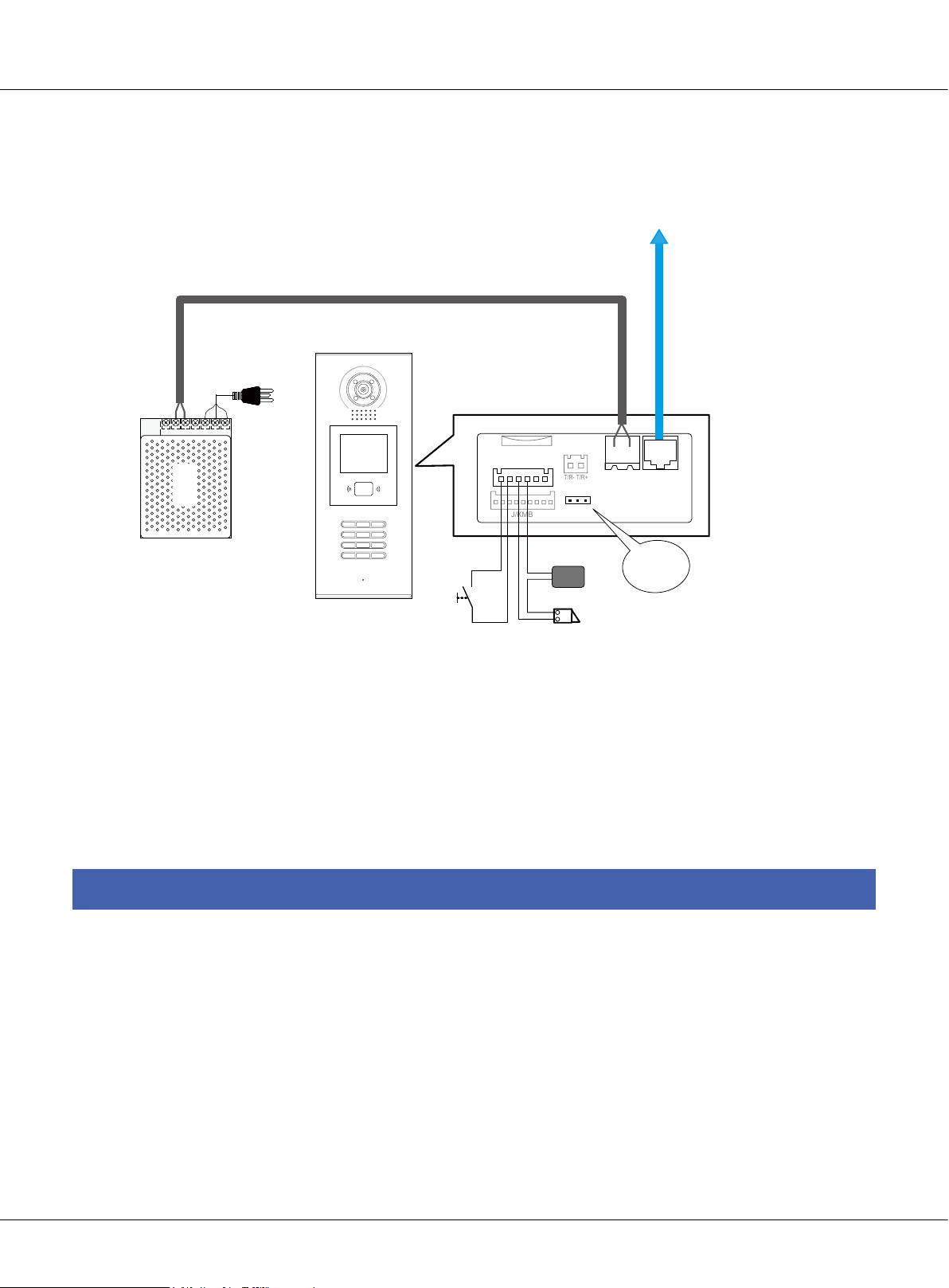
J/KMB
T/R-
T/R+
Chapter 4 K5 System Settings
4.2.2.2§Door§Lock§Controlled§with§External§Power
-
+
PS5
AC
RF CARD
1 2 3
7 8 9
*
654
#0
Exit Button
EB+
EB-
IP-MR18
Note:
1. Please use DC lock and the related DC power supply
2. Remove the JP-LK jumper
3. Set Unlock Output(unlock mode) for diffirent lock types(#8001-3: Unlock Output)
• Power-on-to-unlock type:Unlock Output=0 (by default)
• Power-off-to-unlock type:Unlock Output=1
CN-LK
N.O
To C5-IPC or Distributor
-
+
LK-
LK+
+12V
3
POWER
SUPPLY
LOCK
LOCK
12
JP-LK
CN1
Bus
CN2
Remove the
jumper
§§ 4.3§Monitor§Seng
4.3.1§Concept§of§Address
Address codes are the numbers/letters used by residents, visitors and Switchboard operators to
identify the apartments or villas in the installation. Inside the unit/riser each apartment can be
addressed with a 4 digit code(ABCD),of these 4 digits, the rst 2 digits are meant to be the oor
number, while the last 2 digits serves as the monitor code of each oor. There are 2 calling types
when there is cal made to the monitor: Inside call and Outside call.
Page 60
K5 System Technical Guide
Page 61

Inside call
A call made from the unit door station is the inside call, the inside call can only call the monitor
inside the building. Visitors input the address of monitor (4 digits: ABCD), the door station will call
the monitor right away
Outside Call
Calls from the Switchboard or common door station are outside call. When making this call, 7 digits address is required: XXX-ABCD.
XXX- represents the IP address of C5-IPC of the building
ABCD-represents the address of the monitor
4.3.2§Address§seng§on§Monitor
The address of monitor can be changed to whatever 4-digit number as long as there is no repeated number in the system. Here we have 3 types of monitor, see the following section.
C5-AT27
•
1) In standby mode, touch the screen to enter main menu interface.
K5 System Technical Guide
Page 61
Page 62

Chapter 4 K5 System Settings
2) Touch the User Setup icon to enter setup interface, password will be required, Input 2412 +
to get access to the setup.
3) Now touch the User Code and input the new user code to be the address of the monitor.
Page 62
K5 System Technical Guide
Page 63

C5-AT16
•
1) In Standby Mode, Press the menu button on the surface of the front panel.
2) When it shows the calendar, press the menu button again
K5 System Technical Guide
Page 63
Page 64

Chapter 4 K5 System Settings
3) Now navigate to the Setup and press menu button to enter setup page
Door Station Tone -- 01
Door Bell Tone -- 05
GuardUnit Tone -- 05
No Disturb Mode -- off
Installation...
Exit
4) Go to Installation and input password(2412), then press menu to conrm
Password:
0
*
*
*
Page 64
K5 System Technical Guide
Page 65

5) Go to Room Address…
Alarm In/Out Delay -- 40
Date And Time Set ...
Room Address...
Other Settings...
Information...
Exit
6) Enter the new Room address via navigation button and press Menu to save
Room
6 6 6 6
K5 System Technical Guide
Page 65
Page 66

Chapter 4 K5 System Settings
C5-AT25
•
1) In standby mode, press the Menu button
03/29/2012 Thu.
11 : 44 AM
2) In the Calendar page, press the menu again to enter main menu
Main Menu
Monitor ...
Intercom
Alarm Function ...
User Setup
Close
Exit
OK Select Item
Page 66
K5 System Technical Guide
Page 67

3) Press the button to entry About page
H/W : T3-753 a1.2
S/W: V11.02.27
Voltage: 22.7V
Local Address: 1002
Remote Number: 0
AL. Delay Time: 40/90
Video Standard: PAL
Exit
4) Press the unlock button and hold for 3s when entry about page, then entry Installer Setup page,
just like the following picture shows.
Input 0080 then press Menu button to conrm, then entry room code setting status.
Code Number: [0000]
0010: delete remotes
0011: add remote
0020: set as door bell
0021: not door bell
0022: have door station
0023: no door station
0030: out-delay set
0031: in-delay set
0080: room id set
0090: test armed
0093: direct call gl vd on
0094: direct call gl vd o
8008: MM/DD/YYYY
8009: DD/MM/YYYY
8012: 12 hour format
8013: 24 hour format
2412: restore to default
K5 System Technical Guide
Page 67
Page 68

[----]
[--------]
Chapter 4 K5 System Settings
5) Now Set the new room address for the monitor navigation button, and press menu button to
save the setting
Code Number: [1002]
0010: delete remotes
0011: add remote
0020: set as door bell
0021: not door bell
0022: have door station
0023: no door station
0093: direct call gl vd on
0094: direct call gl vd o
8008: MM/DD/YYYY
8009: DD/MM/YYYY
8012: 12 hour format
8013: 24 hour format
0030: out-delay set
0031: in-delay set
0080: room id set
2412: restore to default
0090: test armed
4.3.3§Address§Seng§with§door§staon
Monitor address also can be set via door station. The steps as follows, take IP-MR18 as an example:
Step1: Entry Monitor Program Page
Please Input Password
Press # key on
Then input 8003 Input the password:
door station
Page 68
K5 System Technical Guide
=== Monitor Program ===
Old M. code [ - - - - ]
New M. code [ - - - - ]
RF CARD
1 2 3
654
7 8 9
#0
*
RF CARD
1 2 3
654
7 8 9
#0
*
>Press Call Button of the
monitor
>Input new Code
>Press # to Program
[ Press Call Button ]
Please Input Password
Then entry Monitor
66666666(Default)
Program page
Page 69

Step2: Activate call function on monitor
C5-ATT27
•
1
2
User Setup Estate
3
4
Monitor
Manual
Intercom
Management
Direct Call
Guard Unit
Intelligent
Home
09/08/2011 Tue. 09:58
Alarm
Security
Multimedia
Close
C5-AT16
•
Press Menu button twice to
entry main page
2
TALK
MONITOR
MENU
Press Call button to entry
Intercom Function page
Press Direct Call Guard
Unit icon
Intercom Function
Call Guard Unit
Direct Call Guard Unit
Intercom Call
Exit
Select Call Guard Unit. Then
press Menu button to conrm
C5-AT25
•
MENU
MONITOR
About OK Selec t Item
TALK
Press Call button to entry
Intercom Function page
Call Select
Alarm to Guard Unit
Direct Call Guard Unit ...
Intercom Menu ...
Exit
OK Select Item
Select Alarm to Guard Unit. Then
press Menu button to conrm
K5 System Technical Guide
Page 69
Page 70

Chapter 4 K5 System Settings
Step3: Upload Monitor Address(Monitor Code)
=== Monitor Program ===
Old M. code [ 0099 ]
New M. code [ - - - - ]
>Press Call Button of the
monitor
>Input new Code
>Press # to Program
[ Input new code ]
The MR18 screen will
show the old monitor code
=== Monitor Program ===
Old M. code [ 0099 ]
New M. code [ 0002 ]
>Press Call Button of the
monitor
>Input new Code
>Press # to Program
[ Programming ]
Input new code, eg,
input 0002, then press
# to conrm, it’ll show
Programming
§§ 4.4§C5-IPC§Seng
C5-IPC is a controlling and network enabling unit.
Wherever network is required, there must be
C5-IPC; wherever C5-IPC is connected, it must
be the only controller. Also, C5-IPC must be used
wherever C5-MDS is applied in the system.
=== Monitor Program ===
Old M. code [ 0099 ]
New M. code [ 0002 ]
>Press Call Button of the
monitor
>Input new Code
>Press # to Program
[ Update ]
It’ll Update if the programming succeeds
JTAG S1 POWER PA VR600
S1
ON DIP
AG
1
2 3 4 5 6
=== Monitor Program ===
Old M. code [ - - - - ]
New M. code [ - - - - ]
>Press Call Button of the
monitor
>Input new Code
>Press # to Program
[ Press Call Button ]
Then back to normal
status, you can repeat
the similar operation to
program next monitor
POWER
LINK
IN-USE
IN-USELINK
VR600
PA
+
C5-IPC
CN-NETJWB(OUT)SW1JP1/2/3
4.4.1§Port§Descripon
SW1
1 2
3
P+ P- P+ P- RS485
JWP
JWB(IN) JWB(OUT) CN(MDS) ETHERNET
RS-485 JWB(IN) CN-MDS
Please refer to 2.3.4.4 (IP Converter: C5-IPC) for more details.
4.4.2§Sengs
4.4.2.1§Level§Switch§seng
SW1 is level switch to match with different distributors. In this system, three types of distributors
are available: C5-F4, C5-F422, C5-F414. Default position is F4DV.
The SW1 setting with different distributor is as below table:
Page 70
K5 System Technical Guide
Page 71

Distributor type SW1 setting
C5-F4
C5-F422
C5-F414
F4/F4DV/F4Q
F4/F4DV/F4Q
F4/F4DV/F4Q
4.4.2.2§DIP§switch§seng
S1 is a 6-bit DIP switch; each of them is designed to have a specied function.
DIP status
•
Each bit can be set to be ON or OFF, shows below:
ON(1)
ON
=
OFF(0)
ON
=
ON
1 2 3 4 5 6
Description of DIP switch
•
Bit NO. Function Status Description
DIP1 MDS selection
DIP2 Audio Channel
DIP3 Video Channel
DIP4
DIP5 Guard Monitor
DIP6
Door station
mode selection
Network video
controlling
ON C5-MDS connected
OFF No C5-MDS connected
ON Apply C5-F414
OFF Apply C5-F4 or C5-F422
ON Apply C5-F422
OFF Apply C5-F4 or C5-F414
ON Door station works as common door station
OFF Door station works as unit door station
ON
OFF Press call button of monitor to call Switchboard
ON
OFF
Press call button of monitor to call Guard Monitor whose
address is 0099
Indoor monitor shows the network video when answering call from Switchboard
Indoor monitor doesn’t display video when answering
call from Switchboard
K5 System Technical Guide
Page 71
Page 72

Chapter 4 K5 System Settings
4.4.2.3§IP§Address§Seng
C5-IPC must be specified an IP address in the network system. And every specified IP address
must be unique. You can use
NOTE: The default IP address of C5-IPC is 192.168.0.2
Setting steps as follows:
1. Connect C5-IPC and PC, and set IP address of PC to 192.168.0.X
Assume that PC IP is 192.168.0.105
IP8210Cong
software to set IP.
POWER
S1
ON DIP
AG
1 2
3
P+ P- P+ P- RS485
1
2 3 4 5 6
SW1
PA
LINK
IN-USE
JWB(IN) JWB(OUT) CN(MDS) ETHERNET
VR600
+
P-
P+
+
C5-IPC
DC output
+
PS5
-
AC in
2. Launch IP8210Cong.exe
1 2
3
P+ P- RS485
-
IP: 192.168.0.105
SW1
JWB(IN) JWB(OUT) CN(MDS) ETHERNET
PC
Page 72
K5 System Technical Guide
Page 73

3. Search the connected C5-IPC
Search...
Click
connected C5-IPC
4. Cong IP address
Select the Device in the Device List
Frame
to start searching the
5. Click on
Assume it’s set to 192.168.0.5,
don’t cha nge Mask & Gate
info, then press OK to conrm,
Mac
then
changed with
Cong
will be automatically
to cong IP
IP
K5 System Technical Guide
Page 73
Page 74

Chapter 4 K5 System Settings
NOTE:
192.168.0.1 & 192.168.0.255 cannot be used by any device in the network.
• IP address range of C5-IPC
POWER
S1
ON DIP
AG
1
1 2
3
P+ P- P+ P- RS485
2 3 4 5 6
SW1
PA
LINK
IN-USE
JWB(IN) JWB(OUT) CN(MDS)ETHERNET
VR600
+
C5-IPC
• PC IP address
IP8210Config
192.168.0.1
192.168.0.255
192.168.0.2 ---- 192.168.0.239
192.168.0.2
192.168.0.3 ---- 192.168.0.254
Because default IP address of C5-IPC is 192.168.0.2, it’ll make a conict if PC is set to 192.168.0.2, then PC cannot search the C5-IPC. That’s why PC should not be set to 192.168.0.2.
Page 74
K5 System Technical Guide
Page 75

4.4.2.4§Parameters§Sengs
V i de o En t r y S y s te m
- - - -- - - -- -- - - -- - - - - -- - - - - --
- - - -- - - -- -- - - -- - - - - -- - - - - --
> > D EB UG S TA T E <<
- - - -- - - -- -- - - -- - - - - -- - - - - --
3 - # Mo ni to r P r og ra m
2 - # Se tu p
1 - # In st al l e r Se t u p
6 - # On li ne D e v ic e s . ..
E X I T: # -9 00 9
5 - # On li ne M o n it o r. . .
- - - -- - - -- -- - To ol s - - - -- - - - - -
4 - # Ca rd M a n a g e
All the parameters of C5-IPC can be set through IP-Device. See IP-Device manual for detail.
4.4.2.5§Controller§Concept
Controller in the system serves as the controlling center, it controls data communicating, audio
and video distribution. Of all the devices, Door station and C5-IPC can be set to be the controller.
Rules must be followed as below:
1) There must be one and only one controller in the system.
2) C5-IPC is designed to be the controller by default, and cannot be set to be non-controller
3) Door station must be set to be non-controller when working with C5-IPC.
How to set Controller on door station:
[ 1 ] I n s t al l e r S et u p
- - - -- -- - -- -- -- - -- -- -- -- - -- -
1. D S Se ri al N O .
2. U n l o c k Ti mi n g
3. U n l o c k Ou t p u t
4. C a rd M em o r y
5. D oo r pl at e Mo d e .. .
6. A u di o Op ti o n . . .
7. P a r am e t e r s . ..
8. I n s ta l l e r Co d e
9. D ef a u l t . . .
- - - -- -- - -- -- -- - -- -- -- -- - -- P r e ss 1 ~9 t o s el ec t
* B a ck
V id e o E n t ry S y s t em
In standby mode, input #9008+password
On the keypad, input 1 to
enter DS Serial NO.
(66666666, by default)
Notes:
1. DS Serial NO. set to be 0, the door station serves as the controller
. . [ 1 ] [ 1 ]
D S S er i a l N O .
[ - ]
0: 1 D S S t an d a l on e
1~ 8 : Mu l t i D S NO.
9: C om m o n D oo r S t a t i on
( 0 ~ 9 )
* B a c k # Sa ve
V id e o E n t ry S y s t em
Input the number according
to the information, then # to
save the parameter
2. DS Serial set to be from 1~8 to be non-controller, if there is no C5-MDS(only one
door station), the door station must be set to 1
3. DS Serial NO. set to 9 to work as common door station
K5 System Technical Guide
Page 75
Page 76

Chapter 4 K5 System Settings
4.4.2.6§Examples:
Work with C5-F4
HI
Note that VD-SET must be set to 120 if the C5-F4 is the last one of the bus
120
HI
120
C5-F4
To Next C5-F4
To other monitors
-
+
C5-F4
To other monitors
FV+FV-P- AUP- P+ P+D1&D2
4B
1R 2W
3Y
GD VD T/R+ T/R- Z1 Z2 Z3 Z4COM COMPR
C5-AT27
1
2
3
4
-
+
PS5
AC
FV+FV-P- AUP- P+ P+D1&D2
4B
1R 2W
-
HI
120
C5-F4
+
3Y
GD VD T/R+ T/R- Z1 Z2 Z3 Z4COM COMPR
1
2
3
4
C5-AT27
C5-F4
ON DIP
Keep 3 jumpers
AG
1 2
P+ P- P+ P- RS485
S1
ON DIP
1
2 3 4 5 6
SW1
3
JWB(IN) JWB(OUT) CN(MDS) ETHERNET
POWER
VR600
PA
LINK
+
IN-USE
F4/F4DV/F4Q
SW1
1 2
3
P-
P+
P+ P- RS485
JWB(IN) JWB(OUT) CN(MDS) ETHERNET
-
+
LAN
C5-IPC
-
+
PS5
AC
RF CARD
1 2 3
7 8 9
*
CN-LK
EB+
EB-
N.O
LK+
LK-
+12V
654
#0
J/KMB JP-LK
T/R-T/R+
-
+
CN2
CN1
Bus
12
3
CAT5
RVV2*1.0mm2
Note that ID Code(#8001-1) setting in MR18 must be set to 1
IP-MR18
Note:
1. SW1 need to be set to F4 position to match with C5-F4.
2. S1 need to be set correctly, all to OFF.
3. Door station need to be connected to the JWB (IN) port of C5-IPC.
4. DS Serial NO. must not be set to 0(while 0 to be the controller)
Page 76
K5 System Technical Guide
Page 77

Work with C5-F422
To Next PS5
-
+
P-P+P+
P+
P-P+P-
Note that VD-SET must be set to VD if the C5-F422 is the last one of the bus
To Next C5-F422
To other monitors
P-
S1
PA
T/R-
ERROR
INUSE
LINK
POWER
T/R+
1ON2
HI / VD
C5-AT27
C5-F422
VD-SET(L=HIGH)
PORT-A PORT-B PORT-C PORT-D JWB(IN) JWB(OUT)
-
+
P-P+P+
P-
S1
P+
P-P+P-
-
-
+
+
AC
PA
T/R-
ERROR
INUSE
LINK
POWER
T/R+
1ON2
PORT-A PORT-B PORT-C PORT-D JWB(IN) JWB(OUT)
To other monitors
VD-SET
HI / VD
1R
Z1
Z2 Z3 Z4 COM COM
PR
1
2
3
4
T/R+
T/R-
GD VD
P+D1&D2
AU P- P+
FV-
2W
4B FV+
3Y
P-
C5-AT27
P+D1&D2
AU P- P+
FV-
2W
4B FV+
3Y
P-
PS5
C5-F422
PORT-A PORT-B PORT-C PORT-D JWB(IN) JWB(OUT)
VD-SET
VD-SET(L=HIGH)
ON
DIP
PORT-A PORT-B PORT-C PORT-D JWB(IN) JWB(OUT)
HI / VD
1R
Z1
Z2 Z3 Z4 COM COM
PR
1
2
3
4
T/R+
T/R-
GD VD
S1
ON
AG
PA
VR600
POWER
DIP
LINK
+
IN-USE
6
1
2 345
C5-IPC
2
1
3
SW1
JWB(IN)
CN(MDS)
RS485
JWB(OUT)
1 2 3
4
7
*
ETHERNET
RF CARD
5
6
9
8
#
0
P+ P- P+ P-
-
-
+
+
AC
PS5
F4/F4DV/F4Q
Keep 3 jumpers
1
2
3
SW1
JWB(OUT) ETHERNETJWB(IN)
-
CN1 CN2
Bus
CN(MDS)
P+ P-
P+
RS485
P-
-
+
CN-LK
EB+
EB-
N.O
LK+
J/KMB
+
T/R- T/R+
LK-
+12V
1
3
2
JP-LK
Note that ID Code(#8001-1) setting in MR18 must be set to 1
IP-MR18
Note:
1. SW1 need to be set to F4DV position to match with C5-F422.
2. S1 need to be set correctly, Bit3 to ON, the rest to OFF.
LAN
CAT5
RVV2*1.0mm
A single cable to connect
P-(Ground) together
2
3. Door station need to be connected to the JWB (IN) port of C5-IPC.
4. DS Serial NO. must not be set to 0(while 0 to be the controller)
K5 System Technical Guide
Page 77
Page 78

Chapter 4 K5 System Settings
Work with C5-F414
To Next PS5
-
+
P-P+P+
P+
P-P+P-
Note that VD-SET must be set to VD if the C5-F414 is the last one of the bus
To Next C5-F414
To other monitors
P-
S1
PA
T/R-
ERROR
INUSE
LINK
POWER
T/R+
1ON2
HI / VD
C5-AT27
C5-F414
VD-SET(L=HIGH)
PORT-A PORT-B PORT-C PORT-D JWB(IN) JWB(OUT)
-
+
P-P+P+
P-
S1
P+
P-P+P-
-
-
+
+
AC
PA
T/R-
ERROR
INUSE
LINK
POWER
T/R+
1ON2
PORT-A PORT-B PORT-C PORT-D JWB(IN) JWB(OUT)
To other monitors
VD-SET
HI / VD
1R
Z1
Z2 Z3 Z4 COM COM
PR
1
2
3
4
T/R+
T/R-
GD VD
P+D1&D2
AU P- P+
FV-
2W
4B FV+
3Y
P-
C5-AT27
P+D1&D2
AU P- P+
FV-
2W
4B FV+
3Y
P-
PS5
C5-F414
PORT-A PORT-B PORT-C PORT-D JWB(IN) JWB(OUT)
VD-SET
VD-SET(L=HIGH)
ON
DIP
PORT-A PORT-B PORT-C PORT-D JWB(IN)
JWB(OUT)
HI / VD
1R
Z1
Z2 Z3 Z4 COM COM
PR
1
2
3
4
T/R+
T/R-
GD VD
S1
ON
AG
PA
VR600
POWER
DIP
LINK
+
IN-USE
6
1
2 345
C5-IPC
2
1
3
SW1
JWB(IN)
JWB(OUT)
P-
P+ P- P+
-
-
+
+
AC
PS5
ETHERNET
CN(MDS)
RS485
RF CARD
1 2 3
5
6
4
9
8
7
#
0
*
F4/F4DV/F4Q
Keep 3 jumpers
1
2
3
SW1
CN(MDS)
P+ P-
P+
P-
-
+
CN-LK
T/R- T/R+
EB+
EB-
N.O
LK+
LK-
+12V
J/KMB
JWB(OUT) ETHERNETJWB(IN)
RS485
-
+
CN1 CN2
Bus
1
3
2
JP-LK
Note that ID Code(#8001-1) setting in MR18 must be set to 1
IP-MR18
Note:
1. SW1 need to be set to F4Q position to match with C5-F414.
2. S1 need to be set correctly, Bit2 to ON, the rest to OFF.
LAN
CAT5
RVV2*1.0mm
A single cable to connect
P-(Ground) together
2
3. Door station need to be connected to the JWB (IN) port of C5-IPC.
4. DS Serial NO. must not be set to 0(while 0 to be the controller).
Page 78
K5 System Technical Guide
Page 79

Work with C5-MDS
This example contains the full function available in the system:
Multi entrances with C5-MDS; Monitor display network video; and one of the monitor serves as
Guard Monitor.
To Next PS5
Note that VD-SET must be set to VD if the C5-F414 is the last one of the bus
To Next C5-F414
-
+
P-P+P+
P-
S1
P+
P-P+P-
PA
T/R-
ERROR
INUSE
LINK
POWER
T/R+
1ON2
C5-F414
VD-SET(L=HIGH)
PORT-A PORT-B PORT-C PORT-D JWB(IN) JWB(OUT)
-
+
P-P+P+
P-
S1
P+
P-P+P-
PA
T/R-
ERROR
INUSE
LINK
POWER
-
-
+
+
AC
PS5
C5-F414
PORT-A PORT-B PORT-C PORT-D JWB(IN) JWB(OUT)
S1
ON
AG
1
2 345
T/R+
1ON2
VD-SET(L=HIGH)
ON
DIP
PA
VR600
POWER
DIP
LINK
+
IN-USE
6
C5-IPC
2
1
3
SW1
JWB(IN)
JWB(OUT)
ETHERNET
P-
CN(MDS)
RS485
P+ P- P+
ON
-
P-P+P+
P-P+P-
+
P-
DIP
S1
P+
PA
ON DIP
T/R-
ERROR
INUSE
LINK
POWER
T/R+
1
2 3 4 5 6
To other monitors
PORT-A PORT-B PORT-C PORT-D JWB(OUT)
To other monitors
PORT-A PORT-B PORT-C PORT-D JWB(IN)
F4/F4DV/F4Q
Remove 3 jumpers
1
2
3
SW1
JWB(IN)
P+ P-
P+
RS485
P-
-
+
JWB(IN)
HI / VD
JWB(OUT)
HI / VD
JWB(OUT) ETHERNET
CN(MDS)
1V 4A/2V 2A/1V 1A
2W
4B FV+
3Y
VD-SET
VD-SET
1R
T/R+
T/R-
GD VD
2W
4B FV+
3Y
1R
T/R+
T/R-
GD VD
FV-
P-
Z1
Z2 Z3 Z4 COM COM
FV-
P-
Z1
Z2 Z3 Z4 COM COM
HI / VD
C5-AT27
P+D1&D2
AU P- P+
PR
1
2
3
4
C5-AT27
P+D1&D2
AU P- P+
PR
1
2
3
4
LAN
C5-MDS
4
JWB(IN4)
JWB(IN3) JWB(IN2) JWB(IN1) JWB(OUT)
-
+
AC
PS5
1 2 3
4
7
*
EB+
RF CARD
5
6
9
8
#
0
EB-
JWB(IN4)
-
+
CN-LK
N.O
J/KMB
CN1 CN2
T/R- T/R+
LK+
LK-
+12V
Bus
1
3
2
JP-LK
Note that ID Code(#8001-1) setting in
IP-MR18
MR18 must be set to 2
123
JWB(IN3)
JWB(IN2)
JWB(IN1)
JWB(OUT)
-
CN-LK
EB+
EB-
J/KMB
+
CN1 CN2
T/R- T/R+
N.O
LK+
LK-
+12V
Bus
1
3
2
JP-LK
1 2 3
4
7
*
Note that ID Code(#8001-1) setting in
MR18 must be set to 1
IP-MR18
Note:
1. C5-MDS needed to be connected to the CN-MDS port of C5-IPC
2. The 3 jumpers on C5-IPC must be removed.
K5 System Technical Guide
CAT5
RF CARD
5
6
9
8
#
0
2
RVV2*1.0mm
A single cable to connect
P-(Ground) together
Page 79
Page 80

Chapter 4 K5 System Settings
Work with Common Door Station
Door station can be set to function as common door station, being able to call all the monitors in
the network system, while unit door station can only call the monitors of its own building.
ON
DIP
S1
ON
AG
1
2 345
PA
POWER
DIP
6
VR600
LINK
IN-USE
+
C5-IPC
2
1
3
SW1
JWB(IN) JWB(OUT) CN(MDS) ETHERNET
P+ P- P+ P-
RS485
-
+
PS5
AC
RF CARD
1 2 3
5
6
4
9
8
7
#
0
*
Keep 3 jumpers
P-
P+
-
+
CN-LK
EB+
EB-
N.O
J/KMB
F4/F4DV/F4Q
LAN
1
2
3
SW1
P+ P-
RS485
T/R- T/R+
LK+
LK-
+12V
1
3
2
JP-LK
JWB(OUT) CN(MDS) ETHERNET
JWB(IN)
-
+
CN1 CN2
Bus
CAT5
RVV2*1.0mm
2
Note that ID Code(#8001-1) setting in MR18 must be set to 9
IP-MR18
Note:
1. SW1 be set as default.
2. S1 need to be set correctly, Bit4 to ON, the rest to OFF.
3. Door station need to be connected to the JWB (IN) port of C5-IPC.
4. DS Serial NO. must be set to 9 (work as common door station).
Page 80
K5 System Technical Guide
Page 81

§§ 4.5§C5-MDS§Seng
C5-MDS is used where there are more than
JWP PA S1
one door stations in one block, to serve as
door station switch, to separate Audio, video
signal form or to different door station.
P-P+P-
PA
ON DIP
1
S1
P+
C5-MDS
JWB(IN4)
JWB(IN3) JWB(IN2) JWB(IN1) JWB(OUT)
JWB(IN4) JWB(IN3) JWB(IN2) JWB(IN1)
4.5.1§Port§Descripon
Please refer to 2.3.4.5( Multi-Door station Switcher: C5-MDS) for more details.
2 3 4 5 6
IN-USE
ERROR
ERROR
INUSE
LINK
POWER
LINK
T/R-
T/R+
POWER
JWB(OUT)
RS-485
4.5.2§Sengs
4.5.2.1§Level§Switch§seng
The C5-MDS will always be used together with C5-IPC, the level switch must be set to be in the
middle position at all times, otherwise there will be video and audio problem between door station and Switchboard when communicating.
1V 4A
2V 2A
1V 1A
4.5.2.2§Address§Seng
In case there are more than one C5-MDS connected to the C5-IPC, the C5-MDS need to be coded
according to the system combination; the rst 2 bits of S1 are for address purpose.
Note:
Level Switch must be set to the
middle position: 2V 2A position.
(Default position: 2V 2A)
K5 System Technical Guide
Page 81
Page 82

Chapter 4 K5 System Settings
ON(1)
ON
=
OFF(0)
ON
=
ON
Note:
Bit1 and Bit2 are for address purpose,
the rest are reserved for late use.
1 2 3 4 5 6
DIP1 DIP2 C5-MDS Address
OFF OFF The rst C5-MDS
ON OFF The second C5-MDS
OFF ON The third C5-MDS
ON ON The fourth C5-MDS
4.5.2.3§The§input§number§of§C5-MDS
Each C5-MDS has 4 inputs from the door station, for C5-MDS with different address, Input number
is unique and different, see below table:
Address Input Description Input number
JWB(IN1) 1
JWB(IN2) 2
First C5-MDS
JWB(IN3) 3
JWB(IN4) 4
JWB(IN1) 5
JWB(IN2) 6
Second C5-MDS
JWB(IN3) 7
JWB(IN4) 8
Note:
Each input of C5-MDS can be connected to only one door station, and the DS Serial NO. On the door station
must be exactly the same with the input number it is connected to; otherwise there will be no video and no
audio.
Page 82
K5 System Technical Guide
Page 83

4.5.3§Connecon§Schemac
With two C5-MDS in the system
To Next PS5
Note that VD-SET must be set to VD if the C5-F414 is the last one of the bus
To Next C5-F414
+
P-P+P+
P-
S1
P+
P-P+P-
PA
T/R-
ERROR
INUSE
LINK
POWER
T/R+
1ON2
C5-F414
VD-SET(L=HIGH)
PORT-A PORT-B PORT-C PORT-D JWB(IN) JWB(OUT)
+
P-P+P+
P-
S1
P+
P-P+P-
PA
T/R-
ERROR
INUSE
LINK
POWER
-
-
+
+
AC
PS5
C5-F414
PORT-A PORT-B PORT-C PORT-D JWB(IN) JWB(OUT)
S1
ON
AG
1
2 345
T/R+
1ON2
VD-SET(L=HIGH)
ON
DIP
PA
VR600
POWER
DIP
LINK
+
IN-USE
6
C5-IPC
2
1
3
SW1
JWB(IN)
CN(MDS)
JWB(OUT)
ETHERNET
RS485
P+ P- P+ P-
ON
DIP
+
-
P-P+P+
P-
S1
P+
P-P+P-
PA
ON DIP
LINK
INUSE
T/R-
ERROR
T/R+
POWER
1
2 3 4 5 6
To other monitors
PORT-A PORT-B PORT-C PORT-D JWB(OUT)
To other monitors
PORT-A PORT-B PORT-C PORT-D JWB(IN)
F4/F4DV/F4Q
Remove 3 jumpers
1
2
3
SW1
JWB(IN)
P+ P-
P+
RS485
P-
-
+
1V 4A/2V 2A/1V 1A
VD-SET
JWB(IN)
HI / VD
VD-SET
JWB(OUT)
HI / VD
JWB(OUT) ETHERNET
CN(MDS)
2W
4B FV+
3Y
1R
T/R+
T/R-
GD VD
2W
4B FV+
3Y
1R
T/R+
T/R-
GD VD
FV-
Z1
FV-
Z1
P-
Z2 Z3 Z4 COM COM
P-
Z2 Z3 Z4 COM COM
HI / VD
C5-AT27
P+D1&D2
AU P- P+
PR
1
2
3
4
C5-AT27
P+D1&D2
AU P- P+
PR
1
2
3
4
LAN
ON
DIP
+
-
P-P+P+
P-
S1
P+
P-P+P-
PA
ON DIP
LINK
INUSE
T/R-
ERROR
T/R+
POWER
1
1V 4A/2V 2A/1V 1A
2 3 4 5 6
C5-MDS
JWB(IN4)
JWB(IN3)
JWB(IN2)
JWB(IN1) JWB(OUT)
8
JWB(IN4)
567
JWB(OUT)
JWB(IN1)
JWB(IN2)
JWB(IN3)
To other door
-
+
AC
CN-LK
EB+
EB-
N.O
PS5
1 2 3
4
7
*
RF CARD
5
6
9
8
#
0
LK+
J/KMB
-
+
CN1 CN2
T/R- T/R+
LK-
+12V
Bus
1
3
2
JP-LK
Note that ID Code(#8001-1) setting in MR18 must be set to 8
4
JWB(IN4)
123
JWB(IN1)
JWB(IN2)
JWB(IN3)
To other door
CN-LK
LK-
EB-
N.O
LK+
EB+
+12V
J/KMB
Note that ID Code(#8001-1) setting in MR18 must be set to 1
IP-MR18
K5 System Technical Guide
C5-MDS
JWB(OUT)
JWB(IN4)
JWB(IN3) JWB(IN2) JWB(IN1) JWB(OUT)
-
+
CN1 CN2
T/R- T/R+
Bus
1
3
2
JP-LK
1 2 3
4
7
*
RF CARD
5
6
9
8
#
0
CAT5
RVV2*1.0mm
2
A single cable to connect
IP-MR18
P-(Ground) together
Page 83
Page 84

Chapter 4 K5 System Settings
§§ 4.6§Accessory§Parts
4.6.1§Distributor
Distributors serves as a branch, they are connected in hand-in –hand-out style in the BUS(BUS
comes out from the door station or from C5-IPC), and function to separate the audio and video
signal from the bus to the monitors, and also power the monitors. Each Distributor has 4 outputs
for the monitors. There are 3 types of distributor available in the system.
4.6.1.1§Connecon§Schemac
The input of distributor can come from Door station or C5-IPC.
Distributor to Door Station
•
HI
Note that VD-SET must be set to 120 if the C5-F4 is the last one of the bus
120
To Next C5-F4
To other monitors
C5-AT27
FV+FV-P- AU P- P+ P+D1&D2
4B
1R 2W
HI
120
C5-F4
-
+
3Y
GD VD T/R+T/R- Z1 Z2 Z3 Z4 COMCOMPR
1
2
3
4
C5-F4
To other monitors
-
+
PS5
AC
FV+FV-P- AU P- P+ P+D1&D2
4B
1R 2W
-
HI
120
C5-F4
+
3Y
GD VD T/R+T/R- Z1 Z2 Z3 Z4 COMCOMPR
C5-AT27
1
2
3
4
C5-F4
-
+
PS5
AC
CN-LK
EB+
EB-
N.O
LK+
LK-
RF CARD
1 2 3
654
7 8 9
#0
*
Note that ID Code(#8001-1) setting in MR18 must be set to 0-F411
+12V
J/KMB JP-LK
T/R-T/R+
-
+
CAT5
CN2
CN1
Bus
12
3
RVV2*1.0mm
2
IP-MR18
Page 84
K5 System Technical Guide
Page 85

Distributor to C5-IPC
•
To Next PS5
-
+
P-P+P+
P-P+P-
Note that VD-SET must be set to VD if the C5-F422 is the last one of the bus
To Next C5-F422
To other monitors
P-
S1
P+
PA
T/R-
ERROR
INUSE
LINK
POWER
T/R+
1ON2
HI / VD
C5-AT27
C5-F422
VD-SET(L=HIGH)
PORT-A PORT-B PORT-C PORT-D JWB(IN) JWB(OUT)
-
+
P-P+P+
P-
S1
P+
P-P+P-
-
-
+
+
AC
PA
T/R-
ERROR
INUSE
LINK
POWER
1ON2
T/R+
PORT-A PORT-B PORT-C PORT-D JWB(IN) JWB(OUT)
To other monitors
VD-SET
HI / VD
1R
Z1
Z2 Z3 Z4 COM COM
PR
1
2
3
4
T/R+
T/R-
GD VD
P+D1&D2
AU P- P+
FV-
2W
4B FV+
3Y
P-
C5-AT27
P+D1&D2
AU P- P+
FV-
2W
4B FV+
3Y
P-
PS5
C5-F422
PORT-A PORT-B PORT-C PORT-D JWB(IN) JWB(OUT)
VD-SET(L=HIGH)
PORT-A PORT-B PORT-C PORT-D JWB(IN) JWB(OUT)
VD-SET
HI / VD
1R
Z1
Z2 Z3 Z4 COM COM
PR
1
2
3
4
T/R+
T/R-
GD VD
ON
DIP
S1
ON
AG
1
PA
VR600
POWER
DIP
LINK
+
IN-USE
6
2 345
C5-IPC
2
1
3
SW1
JWB(IN)
CN(MDS)
RS485
JWB(OUT)
1 2 3
4
7
*
ETHERNET
RF CARD
5
6
9
8
#
0
P+ P- P+ P-
-
-
+
+
AC
PS5
Keep 3 jumpers
P+
+
EB+
EB-
J/KMB
F4/F4DV/F4Q
1
2
3
SW1
JWB(OUT) ETHERNETJWB(IN)
-
CN1 CN2
Bus
CN(MDS)
P+ P-
RS485
P-
-
CN-LK
N.O
LK+
+
T/R- T/R+
LK-
+12V
1
3
2
JP-LK
LAN
CAT5
RVV2*1.0mm
A single cable to connect
2
P-(Ground) together
Note that ID Code(#8001-1) setting in MR18 must be set to 1
IP-MR18
K5 System Technical Guide
Page 85
Page 86

Chapter 4 K5 System Settings
4.6.1.2§Distributor§Types
There are 3 types of distributors in the system: C5-F411, C5-F422 and C5-F414.
C5-F411
Power the monitor
4 outputs for monitor
One audio and one video channel available at a time
C5-F422
Power the monitor
4outputs for monitor
Two audio and two video channels are available at a time
Two door stations can have their separate conversations at the same time
C5-F414
Power the monitor
4 outputs for monitors
One video channel and four audio channels are available at a time,
Maximum four conversations can take place at the same time. One is between door station and
Monitor; the other three are between monitors.
4.6.1.3§Video§Match
Each Distributor must be matched for video. Each distributor was equipped with video match
switch and it has two states: HIGH and VD SET. In one block, only one of the distributors is set to
VD SET, the rest all to be set to HIGH.
The distributor that is at the end of the BUS be set to VD-SET position. The end means the farthest
from the door station or from C5-IPC.
The other distributors are set to HIGH position.
Note:
1) Choose different distributor according to the system function
2) Video match must be set correctly. Otherwise the picture will become too white or too dark.
4.6.2§Picture-Memory-C5-IMC
C5-IMC is a public picture memory. When visitor make a call to the monitor, the C5-IMC will take
a photo of the visitor and saved it. The called monitor and browse the picture taken, but only the
picture which is taken when door station calls the monitor. The other monitors cannot get access
to the pictures saved for other monitors.
Page 86
K5 System Technical Guide
Page 87

Large Capacity:
•
Flexible time setting:
•
The C5-IMC can save up to 800 pieces of pictures
When browsing the pictures on the monitor, the switching time between
different pictures can be changed on the C5-IMC
Automatic room releasing:
•
When the memory is full, the earliest pictures will be deleted to
make room for the new pictures .Also users can delete the pictures by themselves on the monitor.
4.6.2.1§Connecon§Schemac
Connect the C5-IMC as you do a distributor. And one C5-IMC can be connected to the system.
To Next PS5
-
P-P+P+
P-P+P-
Note that VD-SET must be set to VD if the C5-F414 is the last one of the bus
To Next C5-F414
+
P-
S1
P+
PA
T/R-
ERROR
INUSE
LINK
POWER
T/R+
1ON2
To other monitors
HI / VD
C5-AT27
C5-F414
VD-SET(L=HIGH)
PORT-A PORT-B PORT-C PORT-D JWB(IN)JWB(OUT)
-
+
P-P+P+
P-
S1
P+
P-P+P-
PA
T/R-
ERROR
INUSE
LINK
POWER
-
-
+
+
AC
T/R+
1ON2
PORT-A PORT-B PORT-C PORT-D JWB(IN) JWB(OUT)
To other monitors
VD-SET
HI / VD
1R
Z1
Z2 Z3 Z4 COM COM
PR
1
2
3
4
T/R+
T/R-
GD VD
P+D1&D2
AU P- P+
FV-
2W
4B FV+
3Y
P-
C5-AT27
P+D1&D2
AU P- P+
FV-
2W
4B FV+
3Y
P-
PS5
C5-F414
PORT-A PORT-B PORT-C PORT-D JWB(IN)JWB(OUT)
VD-SET(L=HIGH)
PORT-A PORT-B PORT-C PORT-D JWB(IN)
JWB(OUT)
VD-SET
HI / VD
1R
Z1
Z2 Z3 Z4 COM COM
PR
1
2
3
4
T/R+
T/R-
GD VD
ON DIP
1
2 3 45 6
S201
PA201 PA202 PA203 PA204
LED201
LED202
LED203
LED204
HI / VD
C5-IMC
P+
P-
RS485
P+ T/R+
P-P+P-
-
-
+
+
AC
PS5
FM-SET
T/R-
RF CARD
1 2 3
5
6
4
9
8
7
#
0
*
P+ P-
-
+
CN-LK
EB+
EB-
N.O
LK+
LK-
+12V
J/KMB
JWB(IN)
-
+
CN1 CN2
T/R- T/R+
Bus
1
3
2
JP-LK
Note that ID Code(#8001-1) setting in MR18 must be set to 0-F414
FM-SET
JWB(OUT)
K5 System Technical Guide
CAT5
RVV2*1.0mm
2
A single cable to connect
P-(Ground) together
Page 87
Page 88

Chapter 4 K5 System Settings
4.6.3§Access§control-GP-ACS
GP-ACS is access controller. It can work as a standalone access controller or work with C5-IPC to be
connected to the network.
To Next PS5
P-P+P-
-
+
P-P+P+
P+
Note that VD-SET must be set to VD if the C5-F414 is the last one of the bus
To Next C5-F414
To other monitors
P-
S1
PA
T/R-
ERROR
INUSE
LINK
POWER
T/R+
1ON2
HI / VD
C5-AT27
C5-F414
VD-SET(L=HIGH)
PORT-A PORT-B PORT-C PORT-D JWB(IN)JWB(OUT)
-
+
P-P+P+
P-
S1
P+
P-P+P-
PA
T/R-
ERROR
INUSE
LINK
POWER
-
-
+
+
AC
T/R+
1ON2
PORT-A PORT-B PORT-C PORT-D JWB(IN) JWB(OUT)
To other monitors
VD-SET
HI / VD
1R
Z1
Z2 Z3 Z4 COM COM
PR
1
2
3
4
T/R+
T/R-
GD VD
P+D1&D2
AU P- P+
FV-
2W
4B FV+
3Y
P-
C5-AT27
P+D1&D2
AU P- P+
FV-
2W
4B FV+
3Y
P-
PS5
C5-F414
PORT-A PORT-B PORT-C PORT-D JWB(IN)JWB(OUT)
VD-SET
JWB(OUT)
VD-SET(L=HIGH)
ON
DIP
PORT-A PORT-B PORT-C PORT-D
JWB(IN)
HI / VD
1R
Z1
Z2 Z3 Z4 COM COM
PR
1
2
3
4
T/R+
T/R-
GD VD
S1
PA
VR600
POWER
DIP
ON
AG
LINK
+
IN-USE
6
1
2 345
C5-IPC
2
1
3
SW1
JWB(IN) JWB(OUT) CN(MDS) ETHERNET
P+ P- P+ P-
RS485
ON
AC
JP-LK1
2
3
1
JP-LK2
2
3
1
SN-
GP-ACS
P+ A1 P- D1D2 JWB(IN) JWB(OUT)
P+
P-
-
-
+
+
PS5
SN+
P-
EB+
EB-
N.O
POWER LINK IN-USE
ON DIP
LED1
1
2 3 45 6
LED2
S1
LK+
LK-
+12V
BEEP
LED
WG1
WG0
P-
+12V
PA
RS485
F4/F4DV/F4Q
Keep 3 jumpers
1
2
3
SW1
RS485
P+ P-
P-
P+
-
+
DIP
+
P+
JWB(IN)
JWB(OUT)
CN(MDS) ETHERNET
-
P+
D1
P-
A1
P-
-
+
RS485
P-
D2
JWB(IN)
JWB(OUT)
LAN
CAT5
2
1 2 3
4
7
*
-
CN-LK
EB+
EB-
RF CARD
5
6
9
8
#
0
N.O
J/KMB
+
CN1 CN2
T/R- T/R+
LK+
LK-
+12V
Bus
1
3
2
JP-LK
RVV2*1.0mm
A single cable to connect
P-(Ground) together
Note that ID Code(#8001-1) setting in MR18 must be set to 1
Page 88
K5 System Technical Guide
Page 89

4.6.4§Camera§control-CM-IPC
CM-IPC is a device designed for Network camera. Through the CM-IPC, the computer can display
the video of the camera connected to the CM-IPC using the software IP-Agent.
Auto Switching:
•
set to show different cameras by turn.
Multi-camera:
•
The IP-Agent can display the different cameras by itself; the video also can be
Maximum 4 cameras can be connected to the CM-IPC by applying VT-QSW.
LAN
+
-
-
+
PS5
AC
CM-IPC
P+
VD
P-
-
+
1R
VD
VG
P-
IN-USE
POWER
ON
DIP
PA
1
2 3 4
VG
1R
2W
3Y
4B
T/R+
T/R-
P+
IN-USE
POWER
ON
DIP
1
2W
3Y
4B
2 3 4
T/R+
T/R-
PA
JS-VP(OUT)
JS-OS(IN)
X
VD3
VD2
X
1 2 3 4
DIP
ON
QSW
VD1
IN-USE
POWER
Camera 4 Camera 3 Camera 2 Camera 1
CAT5
RVV2*1.0mm
2
Coaxial Cable
K5 System Technical Guide
Page 89
Page 90

Chapter 5 K5 System Softwares
Chapter 5
K5 SYSTEM SOFTWARES
5.1 PC Station Installation ............................................................ 92
5.2 IP Address Setup ................................................................... 96
5.2.1 General Rules for IP Address Setup .................................. 96
5.2.2 IP Address Setup by IP8210-Cong .................................. 96
5.2.3 IP Address Setup by IP Device Software .......................... 101
5.3 IP Device 2012 .................................................................... 104
5.3.1 Introduction ................................................................ 104
5.3.2 Login.......................................................................... 104
5.3.3 Project Property ........................................................... 106
5.3.4 IP Node Cong ............................................................ 107
5.3.5 Block Cong ................................................................ 110
5.3.6 Default project parameters ............................................ 113
5.3.7 Management of Block C5-IPC ......................................... 117
5.3.8 Management of Common C5-IPC .................................... 123
5.3.9 Tip Device ................................................................... 125
5.4 IP Agent 2012 ..................................................................... 126
5.4.1 Introduction ................................................................ 126
Page 90
5.4.2 Login.......................................................................... 126
5.4.3 Operate Interface ........................................................ 127
5.4.4 Monitor Viewer ............................................................ 128
5.4.5 Record Viewer ............................................................. 135
5.4.6 Capture Viewer ............................................................ 138
K5 System Technical Guide
Page 91

5.4.7 Setting ....................................................................... 139
5.5 IP Access 2012 .................................................................... 144
5.5.1 Introduction ................................................................ 144
5.5.2 Login.......................................................................... 144
5.5.3 Access Device Console .................................................. 146
5.5.4 Card Console .............................................................. 150
5.5.5 Pass Rule .................................................................... 153
5.5.6 Report ........................................................................ 154
5.5.7 Report Card ................................................................ 154
5.5.8 Report Event ............................................................... 154
K5 System Technical Guide
Page 91
Page 92

Chapter 5 K5 System Softwares
§§ 5.1§PC§Staon§Installaon
1. Double Click
2. Select language, and then click next.
Setup.exe.
Start to install PC Station.
Page 92
K5 System Technical Guide
Page 93

3. Click Next
4. Select folder for installation, then click next
K5 System Technical Guide
Page 93
Page 94

Chapter 5 K5 System Softwares
5. Click Install button to begin the installation, then waiting till installation nishes.
6. Then click Finish button to conrm it
Page 94
K5 System Technical Guide
Page 95

7. Please note the default login info:
ID: Device
Password: 123456
Server Name: Machine Name + ‘\K2012’
Database Name: K2012
Customers need to enter the Server name and Database name.
K5 System Technical Guide
Page 95
Page 96

Chapter 5 K5 System Softwares
§§ 5.2§IP§Address§Setup
For constructing a DEDICATED LAN for IP system, all network devices must be set to different IP
Address.
• Network device model includes C5-IPC, IP-G21 and CM-IPC and PC Station.
• All network devices can be detected by IP8210 Cong and IP-Device, but only C5-IPC and IPG21 and CM-IPC can be set by these two software. PC Station is set by Windows IP setup.
5.2.1§General§Rules§for§IP§Address§Setup
All the devices must be in the same IP Segment.(We use the segment: 192.168.0.X in this manual )
1. 192.168.0.1 is used as a network gateway. Devices can’t be set to this address
2. All devices must be set a unique IP address & MAC address
3. If more than one device have the same IP address, only one of them can be available by
IP8210-cong or IP-Device.
4. If PC & the device to be set to have the same IP, the device can’t be detected by IP8210 Cong
or IP-Device software
5. Here are the table for range of device IP address
Range Device
192.168.0. 2 – 192.168.0. 240 C5-IPC
192.168.0.241– 192.168.0.246 PC Station(IP-Agent)
192.168.0.247 – 192.168.0.254 Guard Station(IP-G21)
5.2.2§IP§Address§Setup§by§IP8210-Cong
The IP8210-cong is a tool to set the IP address of C5-IPC. For new C5-IPC, IP address of devices are
initialized to the same address(192.168.0.2) ,so it’s recommended that the IP address of devices be
set one by one. It’s easily fullled via IP8210-Cong software.
5.2.2.1§Set§PC§IP§address
Assume that IP of PC is set to 192.168.0. 242
1. See the notication area in the right lower corner of
windows desktop
Page 96
K5 System Technical Guide
Page 97

2. Press
icon in the notication area. It will pop up a window for setting network.
3. Press
4. Select
dow
Properties
Internet Protocol(TCP/IP)
button in the Local Network Status window
item in the Networking tab of Local Network Properties win-
5. Select
Properties
6. Input
button to nish setup
Use the following IP address
window
IP address, Subnet mask
option in the General tab of
Default gateway
and
as following picture shows, then Press OK
Inter Protocol Version (TCP/IP)
K5 System Technical Guide
Page 97
Page 98

Chapter 5 K5 System Softwares
5.2.2.2§Connect§device§to§PC§directly§or§network
The following is a diagram of direct connection:
PS5-24V
2 Wire
C5-IPC
CAT5
IP8210
Config.exe
Ethernet
5.2.2.3§IP8210§Cong§Soware
Run the IP8210-cong
PC
Page 98
K5 System Technical Guide
Page 99

1. Press Search… button to search the device. You can press Stop button to end the search after
the device has been detected. Just like the following picture shows.
2. Select the device in the Device List frame, then press Cong button.
K5 System Technical Guide
Page 99
Page 100

Chapter 5 K5 System Softwares
3. A window will pop up for IP address setting. Modify IP address, but remember to leave the
Mask and Gate as it is, and then press OK button to conrm. Its Mac address will be automatically modied simultaneously.
4. If setup is successful, it will pop up a window to inform you. Press OK to conrm.
Page 100
K5 System Technical Guide
 Loading...