

Page 1
VTECH COMMUNICATIONS LTD. (TELECOM / R&D)
File : Date :8-May-2000 TITLE :
INTERNAL PRODUCT SPECIFICATION
Internal Product Specification for the
VT 9109 BLK
Basic Phone
Revisi on Hi st ory:
Revision Description Page Effective
Date
0 Draft Releas e. All 8 May 00
VTECH TELECOMMUNICATIONS LTD.
FCC ID: EW789-5004-00
JOB #: 226AH0
EXHIBIT #: 5A
DOCUMENT NO. REV.NO.
This document is proprietary to VTech Communications Ltd.
VTech HK R&D info..
0
PAGE
1 of
14
Page 2

VTECH COMMUNICATIONS LTD. (TELECOM / R&D)
File : Date :8-May-2000 TITLE :
INTERNAL PRODUCT SPECIFICATION
Contents
1. OVERVIEW...................................................................................................................................................3
1.1. G
1.2. R
1.3. P
1.4. C
2. FUNCTIONAL LAYOUT.............................................................................................................................6
2.1. H
2.2. B
ENERAL DESCRIPTION
EGULATORY STANDARDS
RELIMINARY FEATURE LIST
...............................................................................................................................3
...........................................................................................................................3
........................................................................................................................3
1.3.1. Basic Features..................................................................................................................................3
1.3.2. Unique Features...............................................................................................................................3
1.3.3. Features Not Provided.....................................................................................................................3
OSMETIC STYLING
.....................................................................................................................................4
1.4.1. Base Unit Line Drawing...................................................................................................................4
1.4.2. Handset Line Drawing .....................................................................................................................5
ANDSET FUNCTIONAL LAYOUT
..................................................................................................................6
2.1.1. Handset LED Indicators...................................................................................................................6
2.1.2. Handset Key Descriptions................................................................................................................6
ASE UNIT FUNCTIONAL LAYOUT
................................................................................................................7
2.2.1. Base Unit LED Indicators................................................................................................................7
2.2.2. Base Unit Key Descriptions .............................................................................................................7
3. OPERATING MODES.................................................................................................................................8
3.1. STANDBY M
3.2. PHONE M
ODE
.......................................................................................................................................8
ODE
............................................................................................................................................8
3.2.1. Dialing Methods...............................................................................................................................9
3.2.2. Redial Buffer ....................................................................................................................................9
3.2.3. Memory Dialing ...............................................................................................................................9
3.3. MEM M
ODE
..............................................................................................................................................10
3.3.1. Speed Dial Programming...............................................................................................................11
3.3.2. Tone/Pulse Select Programming....................................................................................................11
3.4. RINGING M
3.5. PAGE M
ODE
.......................................................................................................................................12
ODE
.............................................................................................................................................12
4. RF LINK OPERATION..............................................................................................................................13
ECURITY CODE
4.1. S
4.2. RF C
HANNEL SELECTION
.........................................................................................................................................13
..........................................................................................................................13
4.2.1. Manual Channel Selection.............................................................................................................13
5. POWER MANAGEMENT .........................................................................................................................14
5.1. B
5.2. L
ATTERY
OW BATTERY INDICATION
...................................................................................................................................................14
.......................................................................................................................14
VTECH TELECOMMUNICATIONS LTD.
FCC ID: EW789-5004-00
JOB #: 226AH0
EXHIBIT #: 5B
DOCUMENT NO. REV.NO.
This document is proprietary to VTech Communications Ltd.
VTech HK R&D info..
0
PAGE
2 of
14
Page 3

VTECH COMMUNICATIONS LTD. (TELECOM / R&D)
File : Date :8-May-2000 TITLE :
INTERNAL PRODUCT SPECIFICATION
1. Overview
This specification defines the functional and electrical performance requirements of the VT 9109 900MHz analog
cordless telephone. The VT 9109 is intended to be compatible wi th most type of central office equipment in use
in Canada, the United States and South America.
1.1. General Description
1.2. Regulatory Standards
As a requirement for sale in the United States, the VT 9109 will comply with the electrical specifications defined
in the following documents:
•
FCC Part 15 Radio Emissions Requirements
•
FCC Part 68 Telephone Line Interface Requirements
•
UL 1950 Safety Requirements
As a requi rement for sale in Canada, the VT 9109 will comply with the electrical specifications defined in the
following documents:
•
IC RSS-210 Radio Emissions Requirements
•
IC CS-03 Telephone Line Interface Requirements
•
CSA 225 Safety Requirements
In a ddition to the above ma nda tory r egulations, the recommendations provided in EIA 470-B will be used as a
guideline.
1.3. Prelimi nary Feature List
The VT 9109 will offer many of the same features as the VT 9108.
1.3.1. Basic Features
1.3.2. Unique Features
1.3.3. Features Not Provided
VTECH TELECOMMUNICATIONS LTD.
FCC ID: EW789-5004-00
JOB #: 226AH0
EXHIBIT #: 5C
DOCUMENT NO. REV.NO.
This document is proprietary to VTech Communications Ltd.
VTech HK R&D info..
0
PAGE
3 of
14
Page 4
VTECH COMMUNICATIONS LTD. (TELECOM / R&D)
File : Date :8-May-2000 TITLE :
INTERNAL PRODUCT SPECIFICATION
1.4. Cosmetic Styling
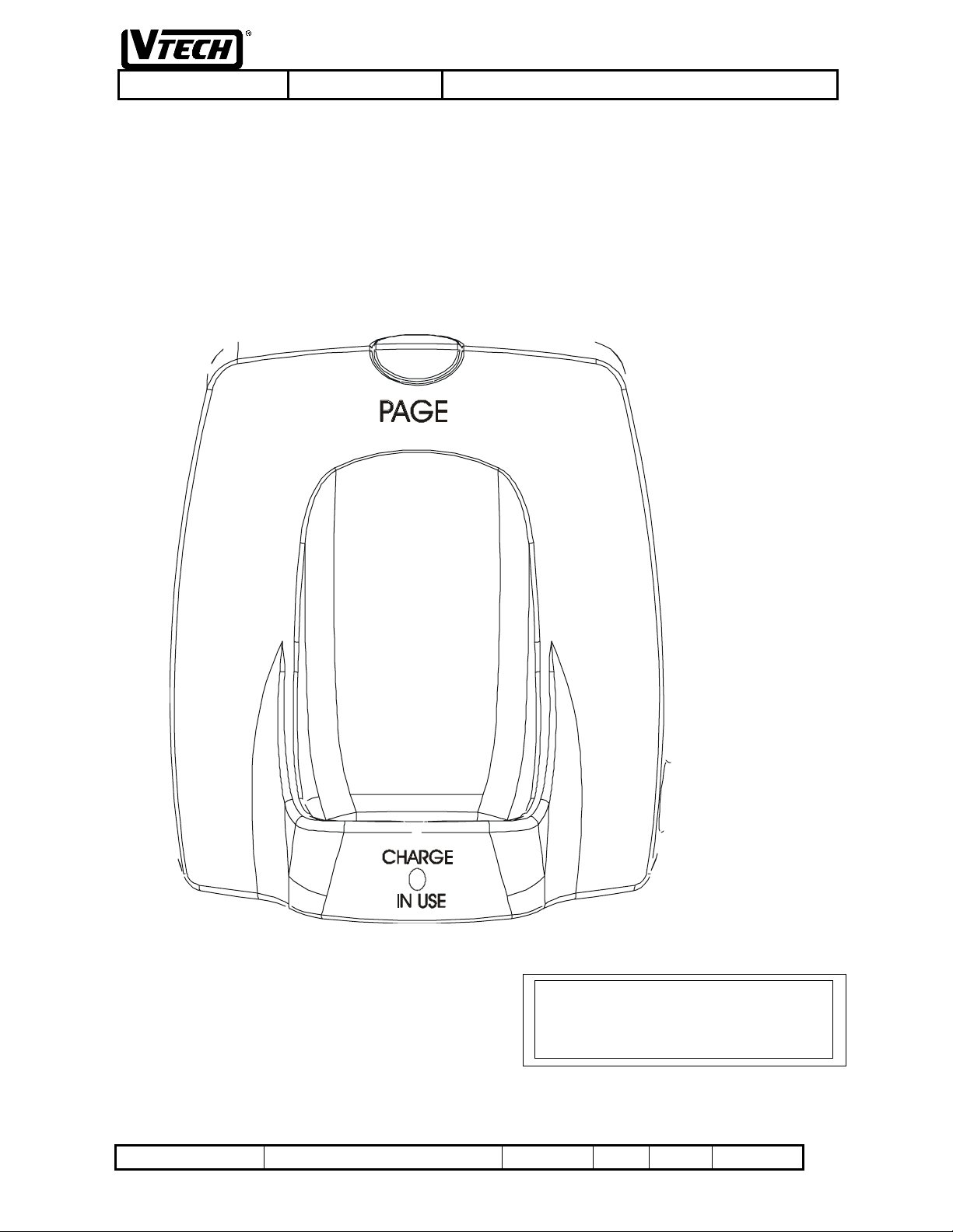
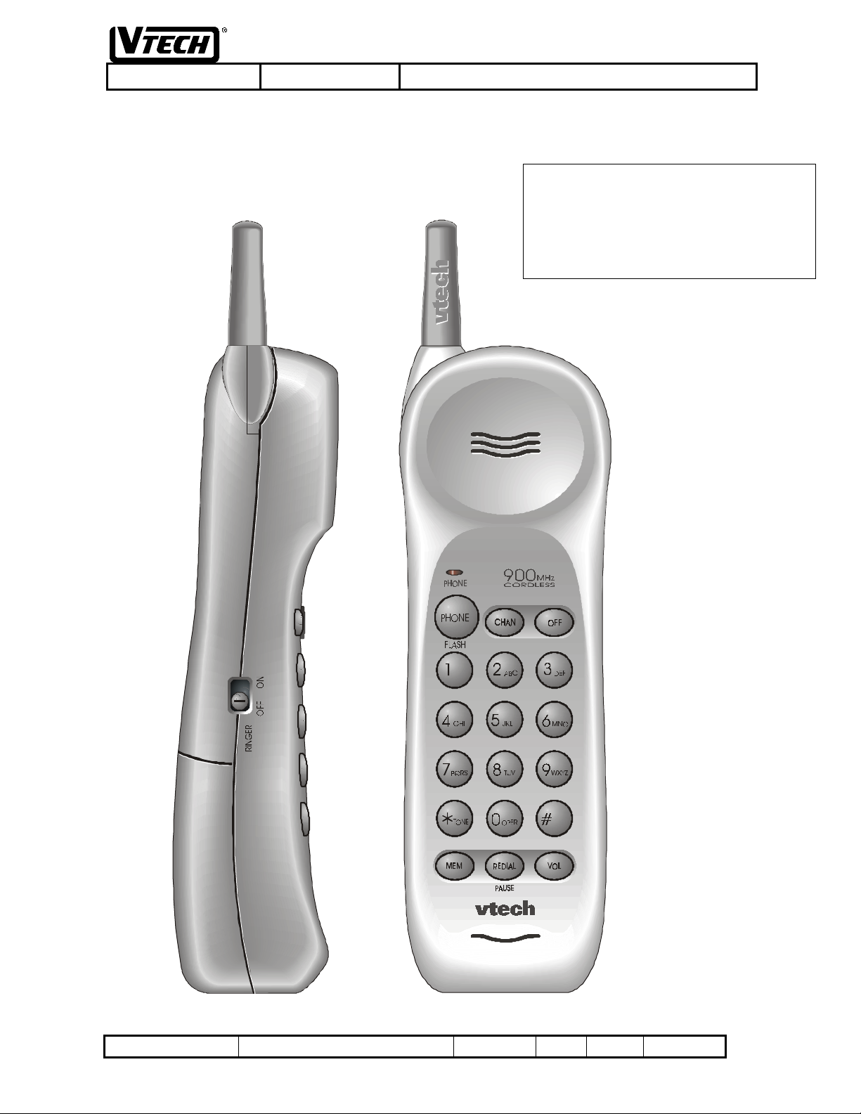
Line drawings for the VT 9109 base unit and handset are in the following sections.
1.4.1. Base Unit Line Drawing
VTECH TELECOMMUNICATIONS LTD.
FCC ID: EW789-5004-00
JOB #: 226AH0
EXHIBI T #: 5A
DOCUMENT NO. REV.NO.
This document is proprietary to VTech Communications Ltd.
VTech HK R&D info..
0
PAGE
4 of
14
Page 5
VTECH COMMUNICATIONS LTD. (TELECOM / R&D)
File : Date :8-May-2000 TITLE :
1.4.2. Handset Line Drawing
INTERNAL PRODUCT SPECIFICATION
VTECH TELECOMMUNICATIONS LTD.
FCC ID: EW789-5004-00
JOB #: 226AH0
EXHIBIT #: 5E
DOCUMENT NO. REV.NO.
This document is proprietary to VTech Communications Ltd.
VTech HK R&D info..
0
PAGE
5 of
14
Page 6

VTECH COMMUNICATIONS LTD. (TELECOM / R&D)
File : Date :8-May-2000 TITLE :
2. Functional Layout
2.1. Handset F un ct ional Layout
- Ref. 1.4.2. Handset Line Drawi ng
2.1.1. Handset LED Indicators
Phone LED
PHONE> key
<
OFF> key
<
CHAN> key
<
- this LED illuminate steadily when the handset is in the PHONE mode. It will flash in
cadence with an incoming ring from the PSTN line. It will flash quickly when the handset is in
the MEM mode. It will flash slowly when a low battery condition in the handset is detected.
2.1.2. Handset Key Descriptions
- this key is used to enter the PHONE mode. If the handset is already in the PHONE
mode, pressing this key will generate a hook-flash on the PSTN line.
- this key is used to exit all mode s of operation and return the handset and base uni t to
the STANDBY mode.
- thi s ke y is use d t o i nitiate a c ha nnel cha nge t o the ne xt a v a ila b le R F c ha nne l. T hi s
key is only active in the PHONE mode; it has no function in the STANDBY mode.
INTERNAL PRODUCT SPECIFICATION
VOL> key
<
PHONE mode; it has no function in the STANDBY mode.
MEM> key
<
The sequence used is <PHONE> <MEM> digit key, where digit key is one of 0-9.
REDIAL/PAUSE> key
<
PHONE mode i f no other di alling keys have been pressed. Pause can also be added into the
memory by pressed this key after any number entry in MEM mode.
Tone/*> key
<
the PHONE mode, and only if the default dialling method is pulse. This key is used to select the
Tone dialling in MEM mode.
<#> key
<Ringer> Switch –
selected to OFF, no ring sound during incoming ringing.
- this key is used to select ear piece volume level. This key is only active in the
- thi s ke y is use d t o e nte r t he memo r y- d ia lling mo d e fo r d i all ing sp e e d d ia l numb e r s .
- this key is used to dial the contents of the redial buffer and active in the
- this key is used to initiate temporary DTMF dialling. This function is only active in
- this key is used to select Pulse dialling in MEM mode.
the s wi t c h i s s e lec t e d to O N, ring s o und d uring i nco mi ng r inging. T he s wit c h i s
VTECH TELECOMMUNICATIONS LTD.
FCC ID: EW789-5004-00
JOB #: 226AH0
EXHIBIT #: 5F
DOCUMENT NO. REV.NO.
This document is proprietary to VTech Communications Ltd.
VTech HK R&D info..
0
PAGE
6 of
14
Page 7
VTECH COMMUNICATIONS LTD. (TELECOM / R&D)
File : Date :8-May-2000 TITLE :
2.2. Base Un it F un ct ional Layout
- Ref. 1.4.1. Base Unit Line Drawing
2.2.1. Base Unit LED Indicators
Charge/ In Use LED
cradle and the handset battery is being charged. And it will flash in cadence with an incoming
ring. This LED also fl ashes momentarily immedi ately after the handset is cradled to indicate
that initialisation (synchronise RF channel) is in progress. This LED illuminates steadily when
the handset out off cradle and in PHONE mode.
- this LED illuminates steadily when the handset is resting in the base unit
2.2.2. Base Unit Key Descriptions
PAGE> key
<
a ser ie s of ri ngs. P res si ng the <P AGE> key a s econd time (w hil e i n the P AGE mod e) will
termi nate PAGE mode, stopping the handset rings. The PAGE mode will also be terminated
automatically after 120 seconds (the STANDBY mode ) o r one p age tone ( the PHONE mode) i s
heard at the handset. This key is inactive if the handset is resting in the base unit cradle.
- this key is used to enter the PAGE mode. In the PAGE mode, the handset will emit
INTERNAL PRODUCT SPECIFICATION
VTECH TELECOMMUNICATIONS LTD.
FCC ID: EW789-5004-00
JOB #: 226AH0
EXHIBIT #: 5G
DOCUMENT NO. REV.NO.
This document is proprietary to VTech Communications Ltd.
VTech HK R&D info..
0
PAGE
7 of
14
Page 8

VTECH COMMUNICATIONS LTD. (TELECOM / R&D)
File : Date :8-May-2000 TITLE :
3. Operating Modes
The VT 9109 has a number of operating modes, including:
•
STANDBY
•
PHONE
•
MEM
•
RINGING
•
PAGE
•
PHONE/PAGE
•
MEM/PAGE
•
MEM/RINGING
These operating modes can be triggered by any of the following events:
•
pressing keys on the handset
•
receiving an incoming call from the PSTN
•
pressing the <PAGE> button on the base unit
•
replacing the handset on the cradle
•
removing the handset from the cradle
•
a timeout (where appropriate)
For this section, the following definitions apply:
• Number Keys
• DTMF Keys
• Dialling Keys
= {<1> <2> <3> <4> <5> <6> <7> <8> <9> <0>}
= {<1> <2> <3> <4> <5> <6> <7> <8> <9> <0> <*> <#>}
= {<1> <2> <3> <4> <5> <6> <7> <8> <9> <0> <*> <#> <REDIAL> <MEM>}
INTERNAL PRODUCT SPECIFICATION
VTECH TELECOMMUNICATIONS LTD.
FCC ID: EW789-5004-00
JOB #: 226AH0
EXHIBIT #: 5H
3.1. STANDBY Mode
The STANDBY mode is the idle mode of the VT 9109. In this mode, both the base unit and handset RF
transmitters are turned off, the base unit has released the PSTN connecti on, and the handset goes into a sleep submode to conserve battery power. The handset ‘wakes up’ (turns on its receiver) periodically to check for an
incoming RF link (incoming PSTN call or Page signal).
When in the STANDBY mode:
PHONE
<
CHAN
<
OFF
<
Dialling Keys
REDIAL
<
MEM
<
Ringing
PAGE
<
On Cradle
Off Cradle
> - causes the VT 9109 to go to the PHONE mode
> - this key is locked out
> - series of on hook data send to base and maintains VT 9109in the STANDBY mode
- these keys are locked out
> - this key is locked out
> - causes the VT 9109 to go to the MEM mode
- causes the VT 9109 to go to the RINGING mode
> - causes the VT 9109 to go to the PAGE mode
- maintains the VT 9109 in the STANDBY mode
- maintains the VT 9109 in the STANDBY mode
3.2. PHONE Mode
The PHONE mode is the main operating mode of the VT 9109. In this mode, a RF link is established between the
handset and the base unit; the base unit has sei zed the PSTN connection; and both transmit and receive audio path
open for voice communication. Dialling is also possible while in the PHONE mode.
Pre ss i ng the <CHAN> key cause s the VT 9109 to seek a new RF channel for operation (refer to section 4.3 for
more details).
DOCUMENT NO. REV.NO.
This document is proprietary to VTech Communications Ltd.
VTech HK R&D info..
0
PAGE
8 of
14
Page 9
VTECH COMMUNICATIONS LTD. (TELECOM / R&D)
File : Date :8-May-2000 TITLE :
Placing the handset into the base unit cradle will automatically release the PSTN connection, and return the phone
to the STANDBY mode (
When in the PHONE mode:
PHONE
<
CHAN
<
OFF
<
> - causes the VT 9109 to return to the STANDBY mode
Dialling Keys
<REDIAL>
MEM
<
> - this key work with digit key for memory dialling
Ringing
<
On Cradle
Off Cradle
- invalid condition
PAGE
> - causes the VT 9109 to go to the PHONE/PAGE mode
auto hang-up
> - causes the base unit to generate a hook flash to the PSTN
> - causes the VT 9109 to change to a new RF channel
- cause the base unit to dial the corresponding digits
- dials the content of redial buffer
- causes the VT 9109 to return to the STANDBY mode
- invalid condition
).
INTERNAL PRODUCT SPECIFICATION
VTECH TELECOMMUNICATIONS LTD.
FCC ID: EW789-5004-00
JOB #: 226AH0
EXHIBIT #: 5I
3.2.1. Dialing Methods
The VT 9109 supports three di alling methods: pulse, tone (DTMF), and temporary DTMF. The pulse or tone
dialling mode can be set as the default dialling method by programming on the handset unit.
Tempor ary DTMF dialling mode is only available w hen the default method is set to pulse . In that case, pressi ng
the <Tone/*> key on the handset will initiate temporary DTMF dialling such that all subsequent digits dialled will
be in DTMF (including <*> and <#>). Temporary DTMF dialling will continue until the VT 9109r eturns to the
STANDBY mode, at which point the default pulse dialling resumes.
During DTMF dialling, the <Tone/*> key will dial the DTMF <*> digit. During Pulse dialling, the <#> key has
no function and will be ignored (even though a key-beep will be generated at the handset).
3.2.2. Redial Buffer
The redial buffer stores the first 32 digits of the number dia lle d during the previous cal l. The number may have
been dialled using the DTMF keys, the <REDIAL> key, the memory dialling feature, or any allowable
combination of these.
The contents of the redial buffer can be dialled to the PSTN by pressing the <REDIAL> key immediately
following the <Phone> key. The redi al buffer becomes invalid as soon as any of the DTMF keys is pre ssed, or i f
the memory dialling feature is used and cannot be accessed until the phone returns to the STANDBY mode.
It is possible to dial further digits after the <REDIAL> key i s pre ssed, ei ther using the DTMF keys, or memorydialling feature. Any suffix digits (including memory dialling) will be appended to the redial buffer.
The redial buffer is stored in the RAM of MCU and will be erased if MCU is reset.
3.2.3. Memory Dialing
Numbers can be dialled out from any of the 10 speed dial memories by pressing the <MEM> key, followed by the
number key corr esponding to the desired memor y l ocation. After the <MEM> key is pressed, only the number
keys (memory loc a tio ns) , the <Phone> key (hook fla sh) and the <OF F> key (r e turn to the STANDBY mode) w i l l
be accepted - the remaining keys on the handset will be locked-out. There is 6 s timeout on the memory-dialling
mode.
It is possible to dial digits before and after using the memory dialling feature; these digits can be dialled using the
DTMF keys, the <REDIAL/PAUSE> key, or the memory dialling feature.
DOCUMENT NO. REV.NO.
This document is proprietary to VTech Communications Ltd.
VTech HK R&D info..
0
PAGE
9 of
14
Page 10

VTECH COMMUNICATIONS LTD. (TELECOM / R&D)
File : Date :8-May-2000 TITLE :
INTERNAL PRODUCT SPECIFICATION
3.3. MEM Mode
The VT 9109 supports three pr ogramming sub-mode s: speed dial programming, tone/pulse sel ect programming.
The speed dial programming sub-mode is used to program a number into one of the 10 speed dial memory
locations; tone/pulse select programming is used to select tone dialling or pulse dialling on base.
When in the main MEM mode:
PHONE
<
CHAN
<
OFF
<
Number Keys
*> Keys
<
REDIAL
<
Ringing
PAGE
<
On Cradle
Off Cradle
6s Timeout
When in the speed dial MEM sub-mode:
PHONE
<
CHAN
<
OFF
<
DTMF Keys
REDIAL
<
MEM
<
VOL
<
Ringing
PAGE
<
On Cradle
Off Cradle
6s Timeout
> - causes the VT 9109 to go to the PHONE mode
> - this key is locked out
> - causes the VT 9109 to go to the STANDBY mode (
- cause the VT 9109 to go to speed dial MEM sub-mode
- cause the VT 9109to go to the tone/pulse select MEM sub-mode
MEM>, <VOL> Keys
>, <
- causes the VT 9109 to go to the RINGING mode
> - causes the VT 9109 to go to the PAGE mode
- causes the VT 9109 to return to the STANDBY mode (
- invalid condition
- returns the VT 9109 to the STANDBY mode (
> - causes the VT 9109 to go to the PHONE mode (
> - this key is locked out
> - causes the VT 9109to go to the STANDBY mode (
- enter the number to be stored
> - this key is locked out
> - and press MEM location number, the number to be stored, return VT 9109 to the
STANDBY mode (
> - this key is locked out
- causes the VT 9109 to go to the RINGING mode
> - causes the VT 9109 to go to the PAGE mode
- returns VT 9109 to return to the STANDBY mode (
- invalid condition
- returns the VT 9109 to the STANDBY mode (
happy tone
- these keys are locked out
)
sad tone
sad tone
sad tone
sad tone
sad tone
sad tone
)
sad tone
)
)
)
)
)
)
When in the tone/pulse select MEM sub-mode:
sad tone
sad tone
sad tone
VTECH TELECOMMUNICATIONS LTD.
FCC ID: EW789-5004-00
JOB #: 226AH0
EXHIBIT #: 5J
<
PHONE
<
CHAN
<
OFF
<
<*>, <#>
Number Keys
MEM
REDIAL>, <VOL> Keys
<
Ringing
PAGE
<
On Cradle
Off Cradle
6s Timeout
> - causes the VT 9109 to go to the PHONE mode (
> - this key is locked out
> - causes the VT 9109 to go to the STANDBY mode (
Keys
– select tone mode or pulse mode dialling on base
- these keys are locked out
> - selection stored, return VT 9109 to the STANDBY mode (
- these keys are locked out
- causes the VT 9109 to go to the RINGING mode
> - causes the VT 9109 to go to the PAGE mode
- causes the VT 9109 to return to the STANDBY mode (
- invalid condition
- returns the VT 9109 to the STANDBY mode (
DOCUMENT NO. REV.NO.
This document is proprietary to VTech Communications Ltd.
VTech HK R&D info..
)
)
happy tone)
sad tone
)
)
0
PAGE
10 of
14
Page 11

VTECH COMMUNICATIONS LTD. (TELECOM / R&D)
File : Date :8-May-2000 TITLE :
INTERNAL PRODUCT SPECIFICATION
VTECH TELECOMMUNICATIONS LTD.
FCC ID: EW789-5004-00
JOB #: 226AH0
EXHIBIT #: 5K
3.3.1. Speed Dial Programming
The VT 9109 has 10 speed dial memory locations, accessed by the digit keys 0 to 9. Each location can hold up to
20 digits.
To MEM a speed dial number:
1. Press the <MEM> key on the handset. The PHONE LED on the handset will flash to indicate the VT
9109 is in the MEM mode.
2. Dial the number to be stored i n the memory location. Numbers are stored in volatile memory on
Handset.
3. Press the <MEM> key on the handset.
4. Enter the memory location to be used for storing the number (0 to 9).
5. The phone will store the digits in the volatile memory on Handset, terminate the MEM mode, and
return to the STANDBY mode. A
programming of the number.
Any of the DTMF diall ing keys ca n be used to store numbers in the spee d dial memory independe nt of the defaul t
diall ing method. If the default dialling method is pulse when using the speed dial number, the digit <#> will be
ignored and the digit <*> will initiate temporary DTMF dialling.
A pause can be inserted into a memory location by pressing the <REDIAL/PAUSE> digit after the pause is
required for two (2) seconds. A key-beep will be heard with the <REDIAL/PAUSE> key-press, and then again
after two (2) seconds; the second key-beep indicates that a pause has been programmed.
happy tone
will be emitted from the handset to indicate successful
3.3.2. Tone/Pulse Select Programming
The VT 9109 supports tone mode dialling and pulse mode dialling on base unit. The tone/pulse select is
programmed as follows:
1. Press the <MEM> key on the handset. The PHONE LED on the handset will flash to indicate the VT
9109 is in the MEM mode.
2. Press the < *> keys to go to the tone/pulse select MEM sub-mode.
3. Press <*> key to select tone mode dialling or press <#> key to select pulse mode dialling.
4. Press the <MEM> key on the handset. The phone will store the selection in the volatile memory on
Handse t, ter minate the MEM mode, and r eturn to the STANDBY mode. A
emitted from the handset to indicate successful programming of the selection.
happy tone
will be
DOCUMENT NO. REV.NO.
This document is proprietary to VTech Communications Ltd.
VTech HK R&D info..
0
PAGE
11 of
14
Page 12

VTECH COMMUNICATIONS LTD. (TELECOM / R&D)
File : Date :8-May-2000 TITLE :
INTERNAL PRODUCT SPECIFICATION
3.4. RINGING Mode
The RINGING mode occurs when a vali d ring signal i s applied to the base unit from the PSTN connecti on. The
base unit establishes a RF link to the handset, and sends commands to the handset causing it to ring (if the ringer is
turned off, the handset will not ring).
If the handset i s a w ay fro m the base unit cr ad l e, pr e ss i ng PHONE key on the handset (e xcep t <OFF >) w ill cause
the VT 9109 to go off-hook and answer the incoming call.
When in the RINGING mode:
PHONE
<
Other Keys
> - causes the VT 9109 to go to the PHONE mode
– these keys are locked out
3.5. PAGE Mode
The PAGE mode o nly occurs if the handse t is i n the STANDBY mode , the handset i s aw ay fr om the b ase unit
cradle, and the <PAGE> button on the base unit is pressed. In the PAGE mode, the handset emits a series of page
tones for 120 seconds; the page tones can be turned off by either pressing the <PHONE> ke y on the handset, o r the
<PAGE> key on the base unit.
When in the PAGE mode:
PHONE
<
CHAN
<
OFF
<
Dialling Keys
VOL
<
Ringing
PAGE
<
On Cradle
Off Cradle
120s Page Timeout
> - causes the VT 9109 to go to the PHONE mode
> - this key is locked out
> - this key is locked out
- these keys are locked out
> - this key is locked out
- causes the VT 9109 to go to the RINGING mode
> - causes the VT 9109 to return to the STANDBY mode
- causes the VT 9109 to return to the STANDBY mode
- invalid condition
- returns the VT 9109to the STANDBY mode
VTECH TELECOMMUNICATIONS LTD.
FCC ID: EW789-5004-00
JOB #: 226AH0
EXHIBIT #: 5L
DOCUMENT NO. REV.NO.
This document is proprietary to VTech Communications Ltd.
VTech HK R&D info..
0
PAGE
12 of
14
Page 13
VTECH COMMUNICATIONS LTD. (TELECOM / R&D)
File : Date :8-May-2000 TITLE :
4. RF Link Operation
4.1. Security Code
1 to 65536 digits possible security code s automatically progra mmed each time
when the Handset is placed in the charge cradle.
4.2. RF Channel Selecti on
4.2.1. Manual Channel Selection
The user can change the channel manually by pressing the Channel
key.
INTERNAL PRODUCT SPECIFICATION
VTECH TELECOMMUNICATIONS LTD.
FCC ID: EW789-5004-00
JOB #: 226AH0
EXHIBIT #: 5M
DOCUMENT NO. REV.NO.
This document is proprietary to VTech Communications Ltd.
VTech HK R&D info..
0
PAGE
13 of
14
Page 14
VTECH COMMUNICATIONS LTD. (TELECOM / R&D)
File : Date :8-May-2000 TITLE :
INTERNAL PRODUCT SPECIFICATION
5. Power Management
The VT 9109 is powered by a battery pack in the handset and by AC power in the base unit.
5.1. Battery
A 3.6V 600mAH Ni-CA ( AA size & with plug) recharge battery is used on the
Handset.
5.2. Low Battery Indi cat ion
In Phone mode, when low battery is detected, the Phone LED flashes and
handset beeps. After about 3 min, the handset will power down.
VTECH TELECOMMUNICATIONS LTD.
FCC ID: EW789-5004-00
JOB #: 226AH0
EXHIBIT #: 5N
DOCUMENT NO. REV.NO.
This document is proprietary to VTech Communications Ltd.
VTech HK R&D info..
0
PAGE
14 of
14
 Loading...