

Page 1
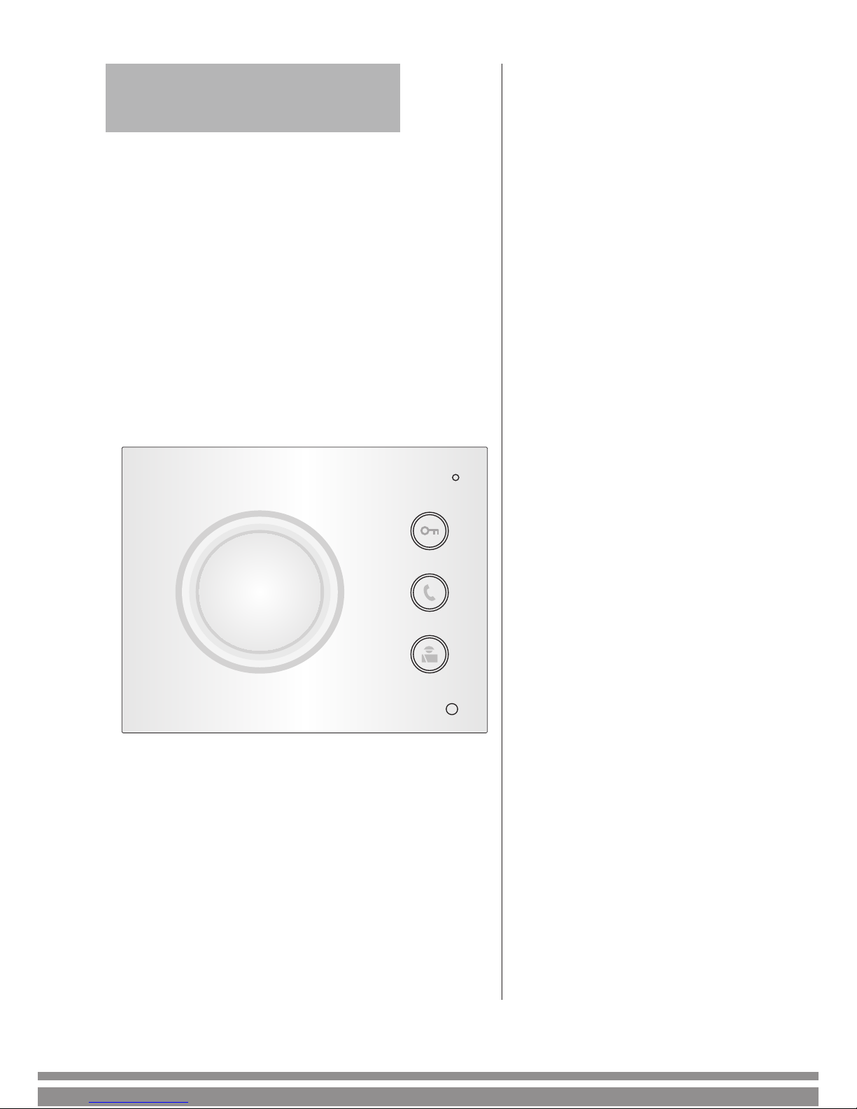
DT-DJ5A
User Manual
Audio Phone
Read this manual carefully before using the product, and keep it well for future use.
Page 2

Page 3
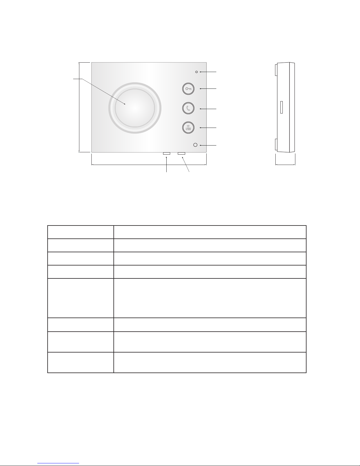
1. Parts and Functions
Side View
88
110 20
Speaker
Microphone
Unlock button
Talk button
Unlock 2nd/Intercom button
Indicator
Tone volume
controller
Talk volume
controller
Speaker Send out voice from the visitor.
Microphone Receive voice from the user.
Unlock button
Press to release the door.
Talk button Press to communicate hands free with visitor
Unlock 2nd button/
Intercom button
During calling/talking state, press Unlock 2nd button to release the second door;
In standby mode, press Call button to activate the intercom
call.
Indicator Power and working indicator.
Tone volume contronller
Adjust the tone volume.
Talk volume contronller
Adjust the talk volume.
Key functions
Page 4
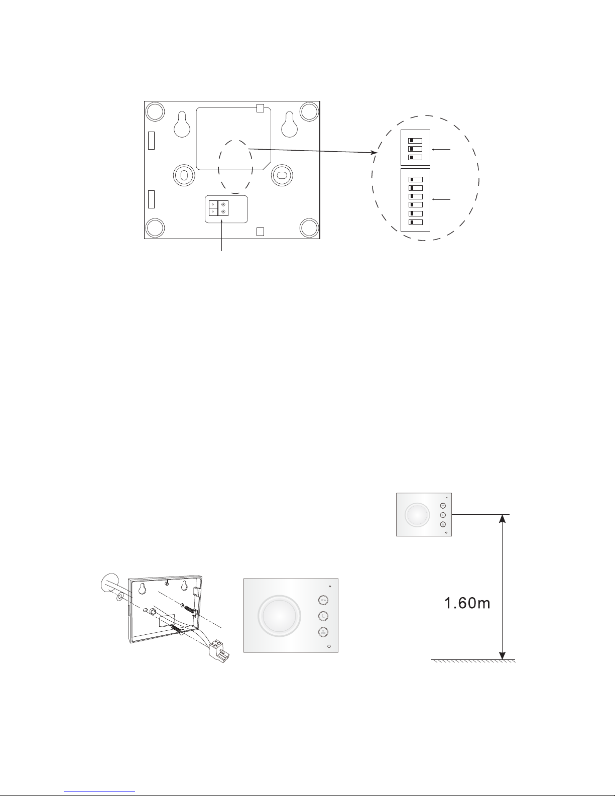
2. Terminal Descriptions
L2 L1
L1, L2
DIP2
DIP1
1 2 3 4 5 6
ON DIP
ON
1 2 3
L1,L2:Bus terminal.
DIP1(Bit1~6):Used to User Code setting.
DIP2(Bit1~3):Used to Slave Monitor Address or Extended Address setting.
3. Unit Mounting
1). Fix 2 screws to the wall at a appropriate height;
2). Connect the system correctly;
3). Attach the audio phone to the bracket.
Page 5
4. Operation Instructions
5. Setup Instructions
1) Door release function: When visitor calls from outdoor station, the monitor rings,
press Talk button to talk with the visitor, then press the Unlock button to open the door.
If the system connect 2 locks, press Unlock 2nd button to open the second door.
2) Intercom call: When the monitor is in standby mode, press Unlock 2nd button/
Intercom button to activate the intercom call, all monitors connected to the system will
ring at the same time. whichever Monitor answers the call, conversation is started. and
the other monitors will stop ringing at the same time.(note that the user code must be
the same for all monitors to activate the intercom call function)
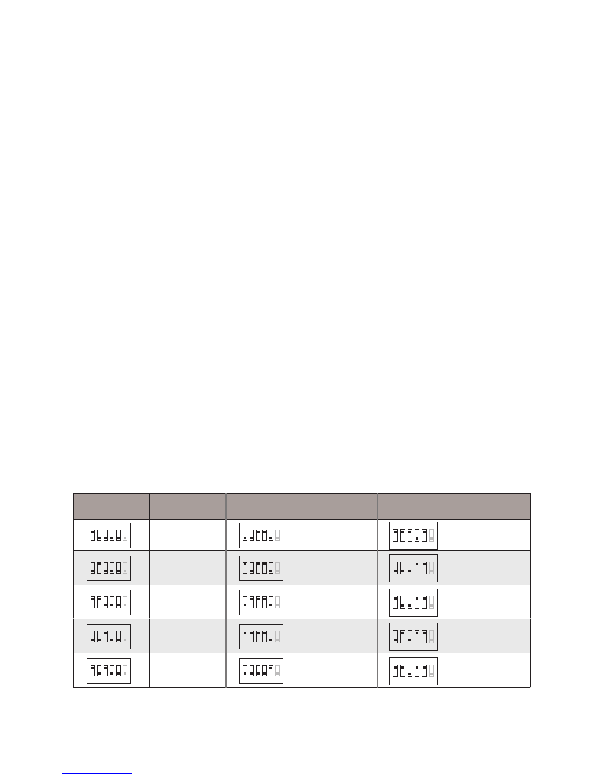
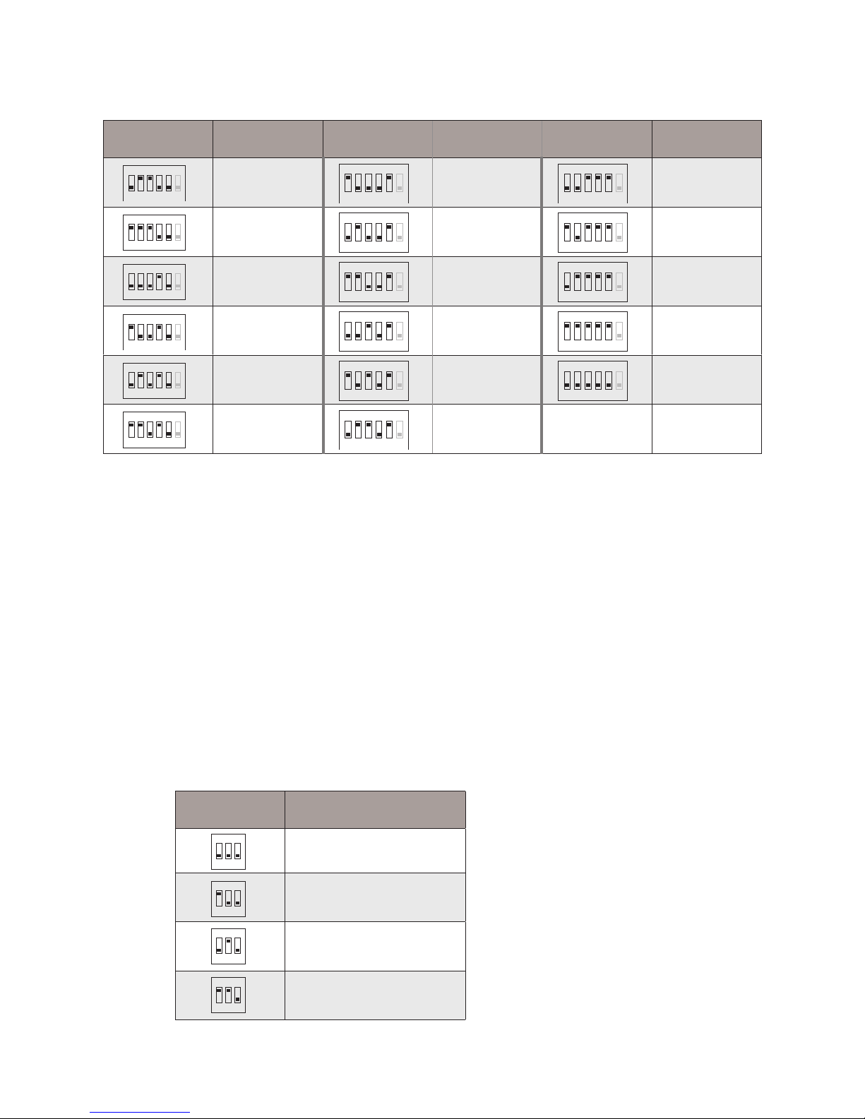
5.1 User Code Setting(DIP1 to set it)
In the DT system, every apartment must have a unique identication called User Code.
The DIP1 switches are used to congure the User Code for each Monitor.
• Bit-1~5 of DIP1 are used to User Code setting. The value is from 1 to 32, which
have 32 different codes for 32 apartments.
• Bit-6 of DIP1 is used to video match.
Bit state User Code Bit state User Code Bit state User Code
1 2 3 4 5 6
ON
Code=1
1 2 3 4 5 6
ON
Code=12
1 2 3 4 5 6
ON
Code=23
1 2 3 4 5 6
ON
Code=2
1 2 3 4 5 6
ON
Code=13
1 2 3 4 5 6
ON
Code=24
1 2 3 4 5 6
ON
Code=3
1 2 3 4 5 6
ON
Code=14
1 2 3 4 5 6
ON
Code=25
1 2 3 4 5 6
ON
Code=4
1 2 3 4 5 6
ON
Code=15
1 2 3 4 5 6
ON
Code=26
1 2 3 4 5 6
ON
Code=5
1 2 3 4 5 6
ON
Code=16
1 2 3 4 5 6
ON
Code=27
Page 6
5.2 Slave Address Or Extended Address Setting(DIP2 to set it)
When multi Monitors are installed in one apartment, these Monitors have to use the
same User Code setting, and the Master/Slave mode should be set on the Monitor.
• Bit-1~2 of DIP2 are used to slave address or extended address setting.
• Bit-3 of DIP2 is used to monitor matched setting, When Bit-3 set to ON / OFF, there
are different usages.
Bit state User Code Bit state User Code Bit state User Code
1 2 3 4 5 6
ON
Code=6
1 2 3 4 5 6
ON
Code=17
1 2 3 4 5 6
ON
Code=28
1 2 3 4 5 6
ON
Code=7
1 2 3 4 5 6
ON
Code=18
1 2 3 4 5 6
ON
Code=29
1 2 3 4 5 6
ON
Code=8
1 2 3 4 5 6
ON
Code=19
1 2 3 4 5 6
ON
Code=30
1 2 3 4 5 6
ON
Code=9
1 2 3 4 5 6
ON
Code=20
1 2 3 4 5 6
ON
Code=31
1 2 3 4 5 6
ON
Code=10
1 2 3 4 5 6
ON
Code=21
1 2 3 4 5 6
ON
Code=32
1 2 3 4 5 6
ON
Code=11
1 2 3 4 5 6
ON
Code=22
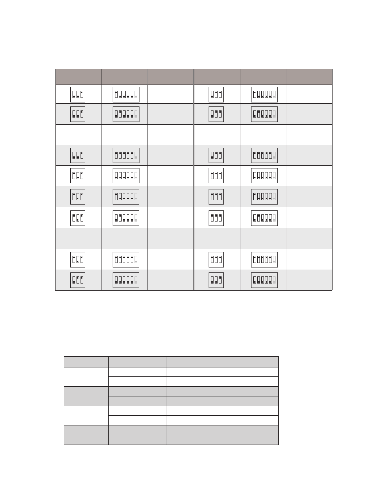
5.2.1 When Bit-3 of DIP2 set to OFF, the Bit-1~2 of DIP2 are used to master/slave
address setting:
DIP2 state Master/Slave type
1 2 3
ON
Master monitor
1 2 3
ON
Slave monitor 1
1 2 3
ON
Slave monitor 2
1 2 3
ON
Slave monitor 3
Page 7
5.3 Ring Tone Setting
1). There are four groups ring tones to choose for you:
5.2.2 When Bit-3 of DIP2 set to ON, the Bit-1~2 of DIP2 and Bit-1~5 of DIP1 are
used to extended address setting:
1 2 3 4 5 6
ON
Code=33
1 2 3
ON
DIP2 state DIP1 state User Code
1 2 3 4 5 6
ON
Code=1
1 2 3
ON
1 2 3 4 5 6
ON
Code=2
1 2 3
ON
.........
1 2 3 4 5 6
ON
Code=31
1 2 3
ON
1 2 3 4 5 6
ON
Code=32
1 2 3
ON
1 2 3 4 5 6
ON
Code=34
1 2 3
ON
.........
1 2 3 4 5 6
ON
Code=63
1 2 3
ON
1 2 3 4 5 6
ON
Code=64
1 2 3
ON
.........
.........
1 2 3 4 5 6
ON
Code=65
1 2 3
ON
1 2 3 4 5 6
ON
Code=66
1 2 3
ON
1 2 3 4 5 6
ON
Code=95
1 2 3
ON
1 2 3 4 5 6
ON
Code=96
1 2 3
ON
1 2 3 4 5 6
ON
Code=97
1 2 3
ON
1 2 3 4 5 6
ON
Code=98
1 2 3
ON
1 2 3
ON
1 2 3 4 5 6
ON
Code=127
1 2 3
ON
1 2 3 4 5 6
ON
Code=128
DIP2 state DIP1 state User Code
Group name Items
Songs
Group1
Door Station DINGDONG
Intercom Call TELEPHONE_RING
Group2
Door Station JINGLE_DELL
Intercom Call CARMAN
Group3
Door Station HAPPY_BIRTHDAY
Intercom Call SONATINE
Group4
Door Station DOREME
Intercom Call RHYTHM_OF_THE
Page 8

2). Press and hold Talk button in standby mode to enter the state of ring tone setting,
and then each time you press Unlock 2nd button to replace a group of ring tones. Four
groups ring tones cycle:
Group1 Group2 Group3 Group4.
press Unlock 2nd press Unlock 2nd press Unlock 2nd
press Unlock 2nd
3). Press Talk button to exit the setting.
6. Specication
The design and specications can be changed without notice to the user. Right to interpret and copyright of this manual are preserved.
●Power Supply: DC24V
●Power Consumption: standby 16mA,working 56mA
●Working Temperature: -15ºC ~ +55ºC;
●Wiring: 2 wires, non-polarity
●Dimension: 88(H)X110(W)X20(D)mm
 Loading...