

Page 1

1
Contents
Introduction ……………………………………………………………………………. 2
Front Panel …………………………………………………………………………….. 4
Rear Panel ……………………………………………………………………………... 5
Installation ……………………………………………………………………………… 6
Bias Adjustment ………………………………………………………………………. 7
U/L and Tetrode Mode ……………………………………………………………….. 8
Tube Replacement ……………………………………………………………………. 9
Fuse Replacement ……………………………………………………………………. 12
Maintenance …………………………………………………………………………… 13
Troubleshooting ………………………………………………………………………. 14
Specifications …………………………………………………………………………. 15
Maintenance Log ……………………………………………………………………… 16
Warranty ………………………………………………………………………………… 17
Page 2

2
Introduction
THANK YOU for purchasing the VacuumTubeAmps.com Mark 1 Power Amplifier, designed,
engineered and hand built in the U.S.
Features:
User selectable Tetrode or Ultra Linear modes via a front panel switch.
Front panel bias controls for each of the four 7591A output tubes allows the audiophile to
balance the output stage for perfect push-pull operation.
Four high quality analog front panel meters allows for continuous monitoring of the output
stage, and provides an early warning of possible tube failure.
Gold plated RCA input sockets.
Gold plated five way speaker jacks.
Gold plated tube sockets
Soft start power supply greatly extends the life of components and tubes.
High end potted output transformers provides a choice of 4Ω or 8Ω speakers.
Toroid power transformers are used for high efficiency and low magnetic radiation.
Thermostatically controlled ball bearing fan exhausts heat for long life.
Variable density isolation feet.
Beautiful solid oak side panels for a power amplifier that looks as great as it sounds.
Thank you again, and enjoy your new Mark 1 Power Amplifier!
Michael A. Burrows, Owner, VacuumTubeAmps.com.
Email: [email protected]
Fax: 540-341-1034
All rights reserved. No part of this publication may be reproduced, or transmitted, in any form or by any means,
electronic, mechanical, recording, or otherwise, without the prior permission of VACUUMTUBEAMPS.COM.
Page 3
3
Front Panel
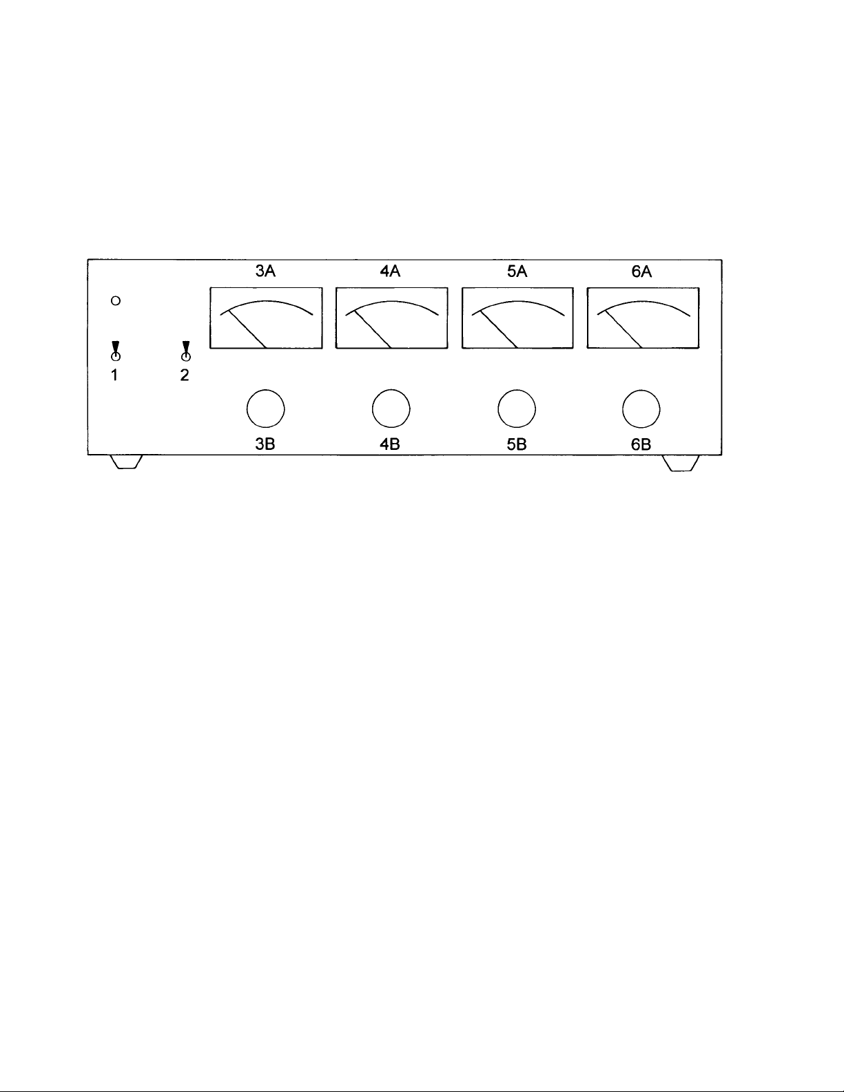
1 POWER SWITCH Turns power on or off. The Mark 1 incorporates a time
delay circuit that delays startup to allow the tubes to warm up before high
voltage is applied to the various amplifier stages.
2 U/L – TETRODE SWITCH
3A-6A BIAS METERS Provides a visual indication of the four output tubes.
3B-6B BIAS CONTROLS
on the four output tubes.
User accessible controls for adjusting the bias voltage
Provides a choice between U/L and Tetrode mode.
Page 4
4
Rear Panel
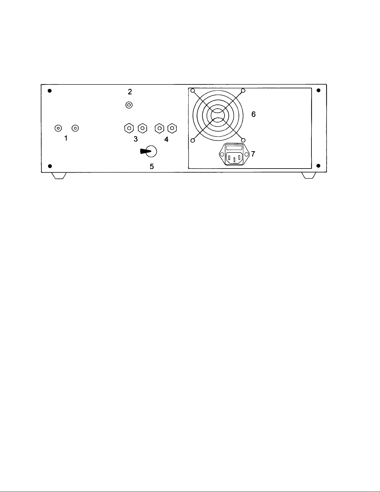
1 Input Jacks
a red band; left channel jack has a white band.
RCA jacks for connection to a line amplifier. Right channel jack has
2 Ground Screw For connecting to ancillary equipment.
3 Left Speaker 5 way binding post.
4 Right Speaker 5 way binding post.
5 Speaker Impedance Switch Allows matching for 4Ω or 8Ω speakers.
6 Cooling Fan Cools the MARK 1.
7 AC Power Connector/Fuse For connection to a 120VAC receptacle, and
5 X 20 MM fuse.
Page 5

5
Installation
1. Carefully unpack the shipping box and save for future use. Don’t touch the front panel bias
controls.
2. Set the MARK 1 in a place that is out of reach of children and pets, and away from sources
of moisture and water.
Caution! Do not put the Mark 1 in an enclosed cabinet! This power amplifier
produces heat, and must have at least three inches of free space between the fan and
wall, and at least twelve inches of free space above the top of the unit. Do not set the
unit on any material (carpet, foam, etc.) that can block the ventilation holes on the
bottom of the unit.
Warning! Never place anything on top of the Mark 1! To do so increases the risk of
fire, and will greatly reduce the life of the unit.
3. Do not connect your preamplifier or line stage at this time.
4. Set the Speaker Impedance Switch to match your speakers impedance.
5. Connect your speakers to the Left/Right Speaker binding posts. The black post connects
to the negative (-) speaker wire. The red post connects to the positive (+) speaker wire. Do
not use a wrench to tighten the binding post, otherwise they might break.
6. Never operate the Mark 1 without a speaker connected! Always turn off the unit before
connecting or disconnecting speakers.
7. Make sure the Mark 1’s power switch is off.
8. Insert the AC power cord connector firmly into the AC/Fuse socket on the back of the unit
below the fan. Insert the other end into a 120VAC, 60Hz receptacle.
9. Set Bias controls, next page.
Page 6
6
Bias Adjustment
The MARK 1 has four user adjustable front panel bias controls, as well as four analog meters
for monitoring the output tubes.
The meters were properly adjusted before shipping. However, the meter’s pointer may have
shifted slightly during shipment.
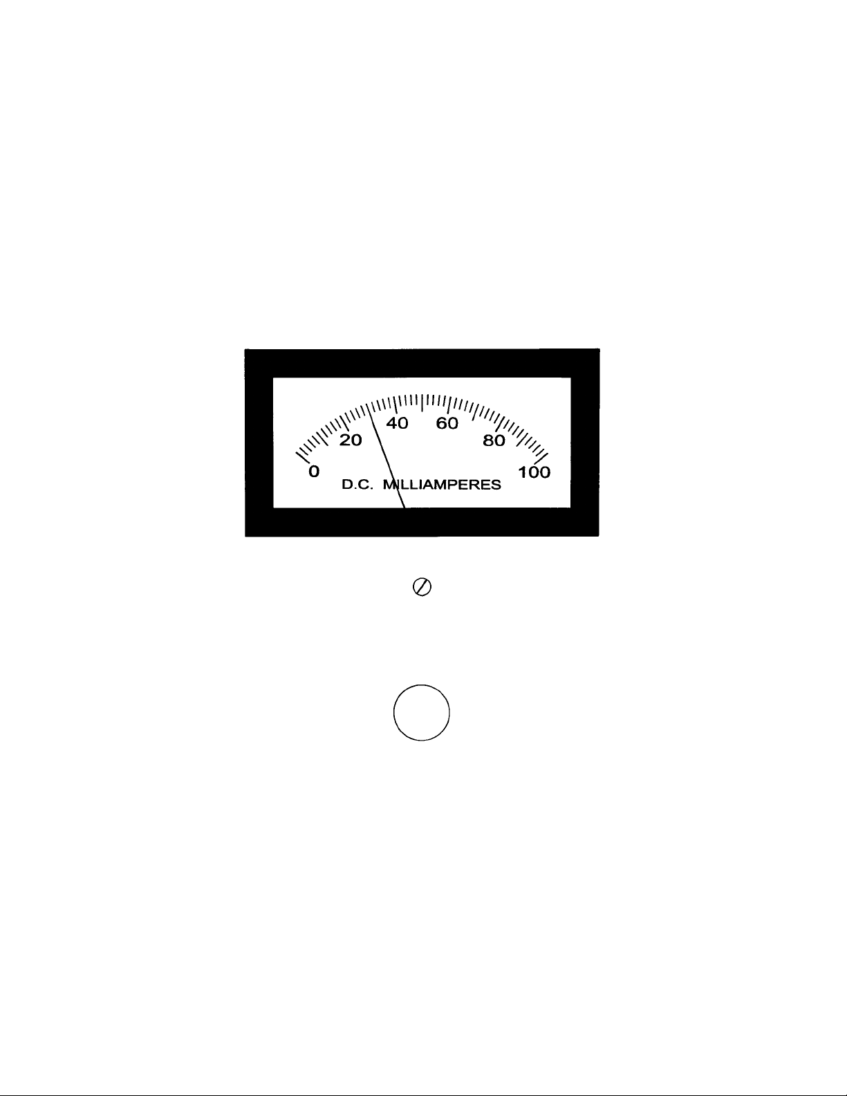
Using a small flat-bladed screwdriver, slowly turn the pointer adjust screw (located just below
the meters’ bezel) so that the pointer is exactly on the “0” tick mark.
With only the speakers connected, turn on the MARK 1. After about thirty seconds, the
meter’s pointer will briefly swing to the right. Initially adjust each bias control so that the
pointer indicates 24 mA (milliamperes). Each major tick point represents 10 mA, while each
minor tick point represents 2 mA.
Keep the MARK 1 turned on, and watch the meter’s pointers slowly move to the right as the
unit warms up. Make sure that the pointer does not go above 30 mA as shown in the
illustration.
After two hours, adjust the bias controls so that all meters read 30 mA.
Page 7

7
Bias Adjustment (cont.)
Turn off the MARK 1, and connect your preamplifier or line stage to the input jacks on the
back panel.
Turn on your preamplifier or line stage, as well as any other ancillary audio equipment, and
allow one minute before turning on the Mark 1.
The reason for this delay is due to certain components in electronic equipment known as
capacitors, require a certain time to charge with voltage. During this “charge-up” process, a
high power pulse of energy will surge through the MARK 1, possibly destroying your
speakers and causing severe damage to the MARK 1.
Don’t become obsessed with the bias controls and meters! Because the Mark 1 uses an
unregulated power supply, normal variations in household voltages will cause the meters to
indicate either an increase or decrease from the 30 mA bias point.
Example 1: You set all four meters to exactly 30 mA. Suddenly, the meters all read 28 mA.
What happened? Household appliances that consume a lot of power will cause the AC line
voltage to drop. When the AC line voltage drops, the high voltage in the MARK 1 will also
drop, resulting in a drop in meter current. Air conditioners, clothes dryers, heat pumps, etc.
are good examples of high power users that switch on and off.
Example 2: During very cold or very hot weather, power utilities must take precautions to
protect their equipment from damage caused by high consumer demands. Power utilities will
lower the voltage on their lines, which will result in a lower meter reading on the MARK 1.
When power demands are low, power utilities will increase the voltage on their lines. The
result is an increase of high voltage in the MARK 1, which might result in the meters
indicating 32 mA!
Instead of worrying about whether the meters indicate 28 mA or 32 mA at any given moment,
enjoy the music!
The important thing to keep in mind is whether or not the output tubes are in balance. If all
four meters indicate the same current, preferably 30 mA, all is well with the output tubes.
When it becomes impossible to adjust one or more output tubes, or if one meter suddenly
indicates a very high (40 mA) or very low (20 mA) reading, it might be an early warning that
an output tube is about to fail. See Tube Replacement.
Note: When listening to music that contains very deep bass, or at loud sound levels, the
meter’s pointers will swing wildly back and forth; this is normal and not a problem.
Always adjust the bias when the preamplifier or line stage is turned off.
Page 8

8
U/L and Tetrode Mode
The Mark 1 provides the audiophile with the choice of operating the amplifier in either U/L
Mode (Ultra-Linear) or Tetrode Mode.
The U/L – Tetrode switch can be toggled between both while listening to your favorite music.
There is very little agreement among audiophiles as to which mode is best; so it is really up to
you to decide what sounds best.
U/L generally produces a cleaner, more transparent musical quality, favored by musicians
who play acoustic instruments, as well as vocalists. However, there is a reduction in power
output.
Tetrode produces a slightly different musical quality, favored by musicians who play
electronic instruments, as well as popular, rock, etc. Tetrode provides the maximum power
output the Mark 1 can produce.
Which is best, U/L or Tetrode mode? No one but you can answer that question. That would
be the same as asking, “How much salt should I put on my food?”.
Listen to your own ears, and decide for yourself.
The Mark 1 uses a thermostatically controlled fan, which is always on when the unit is turned
on. When the unit is turned off, and the internal temperature is above 120°F, the fan will
continue to run until the internal temperature drops below 90°F.
Because the Mark 1 uses four large steel transformers, they will continue to produce heat
after the unit is shut off, just like an auto engine. So the fan will “cycle” on and off until the
internal temperature remains below 90°F. This “cycling” is normal, and doesn’t indicate a
problem.
Notice: Make sure that nothing becomes lodged in the fan, such as audio cables, AC line
cord, etc. Remember, allow at least 3” of space between the fan and any object.
Page 9
9
Tube Replacement
The moment tubes are placed in service, there is a slow but steady decline in the cathodes
(the part of the tube that glows red.) ability to emit electrons. This results in a loss of power,
inability to bias the output tube or tubes, and increased distortion.
It is not possible to accurately predict how long tubes will last. The 12AX7 and 12AT7 tubes
could last as long as 10,000 hours, and the 7591A output tubes could last as long as 3000 to
4000 hours. However, it is best to replace them before they fail catastrophically, causing
severe damage to the MARK 1 and your speakers.
It is recommended that the 12AX7 and 12AT7 tubes be replaced every 3000 hours, and
replaced together. The 12AX7 supplies a bias voltage to the 12AT7, so if the 12AX7 fails it
will destroy the 12AT7 and associated components.
The 7591A output tubes should be replaced after 2000 hours, and more often for critical
listening. For best results, always purchase a matched quad of 7591A’s.
Warning! Do not use 7591XYZ tubes! They are not the same as the 7591A, and will
destroy the Mark 1!
To replace the tubes, turn off the Mark 1 and remove all cables, including the AC power cord.
Turn the unit around so the back faces you.
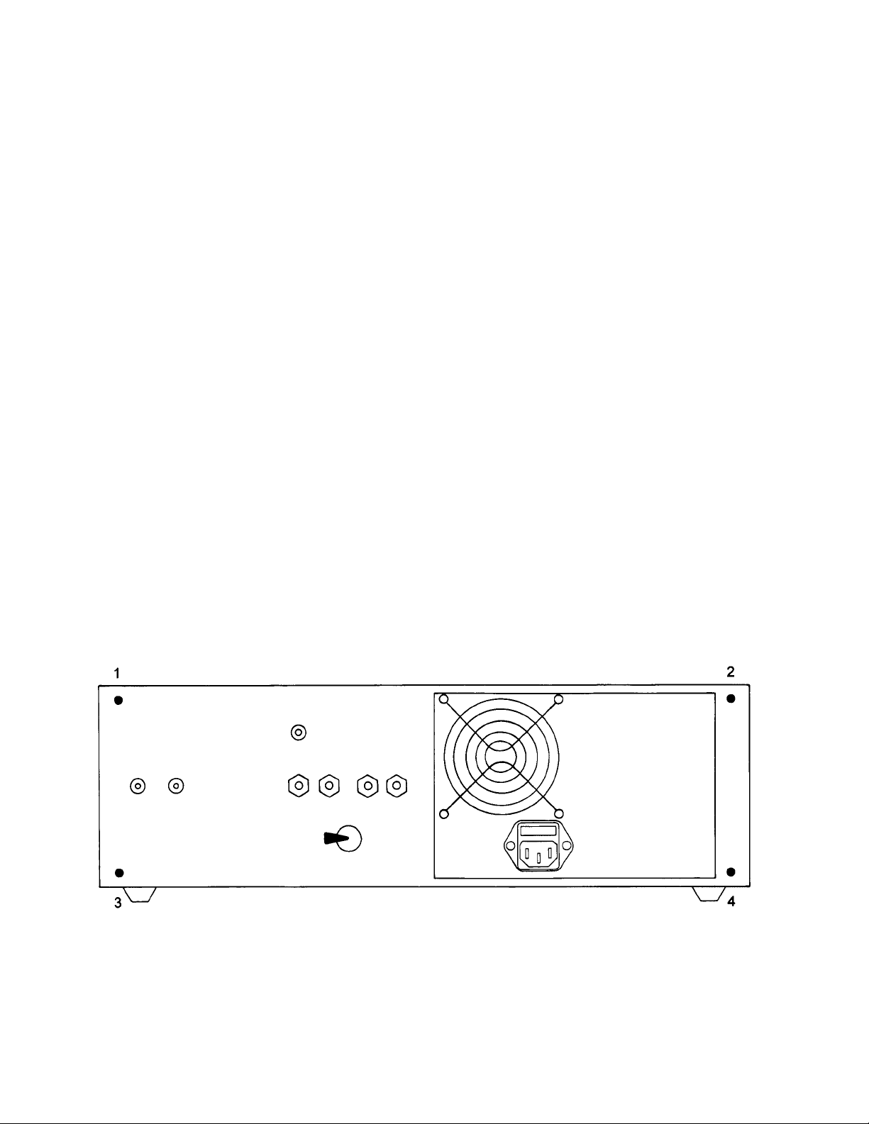
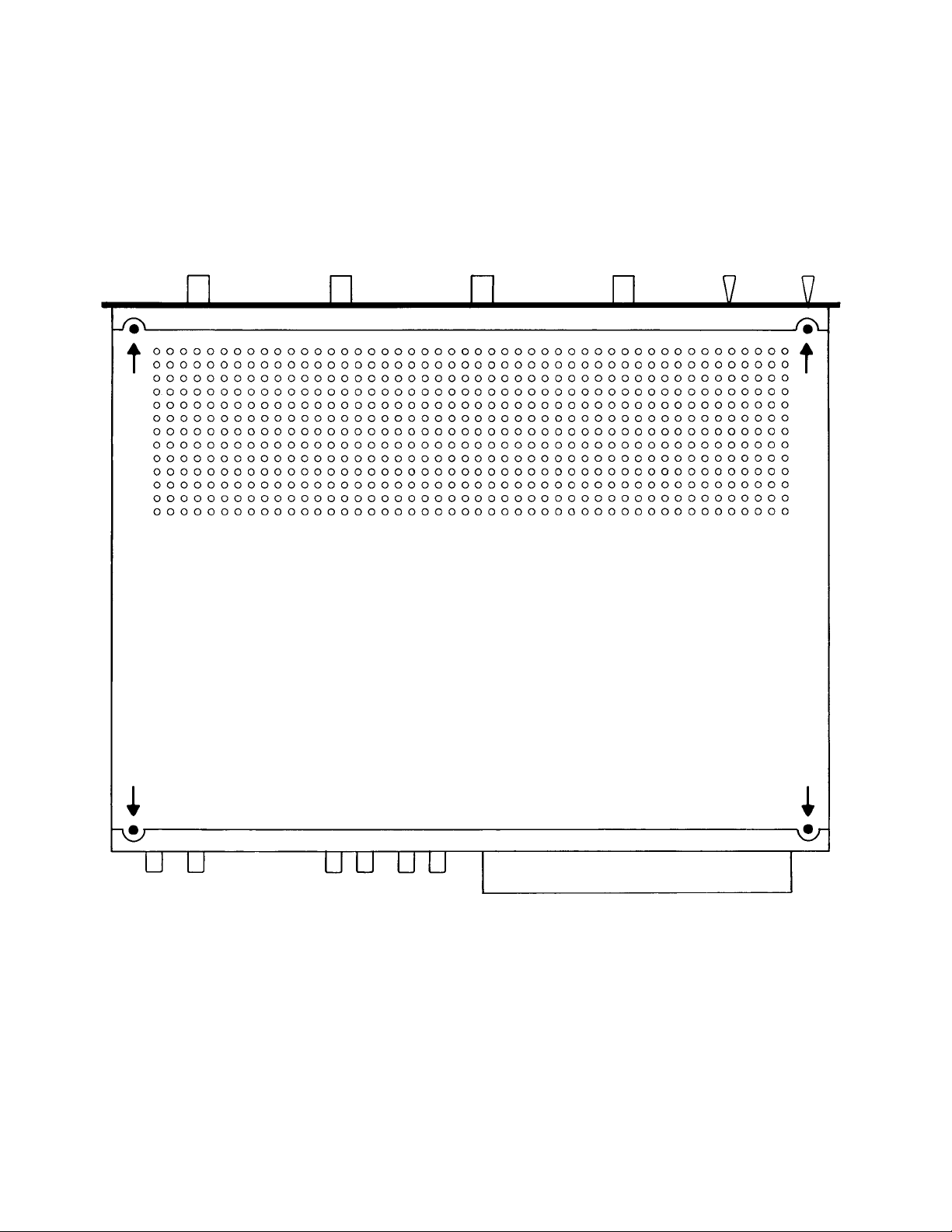
Using a number one Philips screwdriver, turn screws 1, 2, 3 and 4 counterclockwise eight
times. Do not remove screws.
Page 10
10
Tube Replacement (cont.)
Remove the four top screws as indicated by the arrows. Grasp the back panel with both
hands and pull toward you. Slide the top panel slightly back. The top panel can now be
removed.
To remove a tube, pull straight up while slightly rocking it. Be careful not to damage or touch
other components. Rubber gloves are recommended.
Page 11
11
Tube Replacement (cont.)
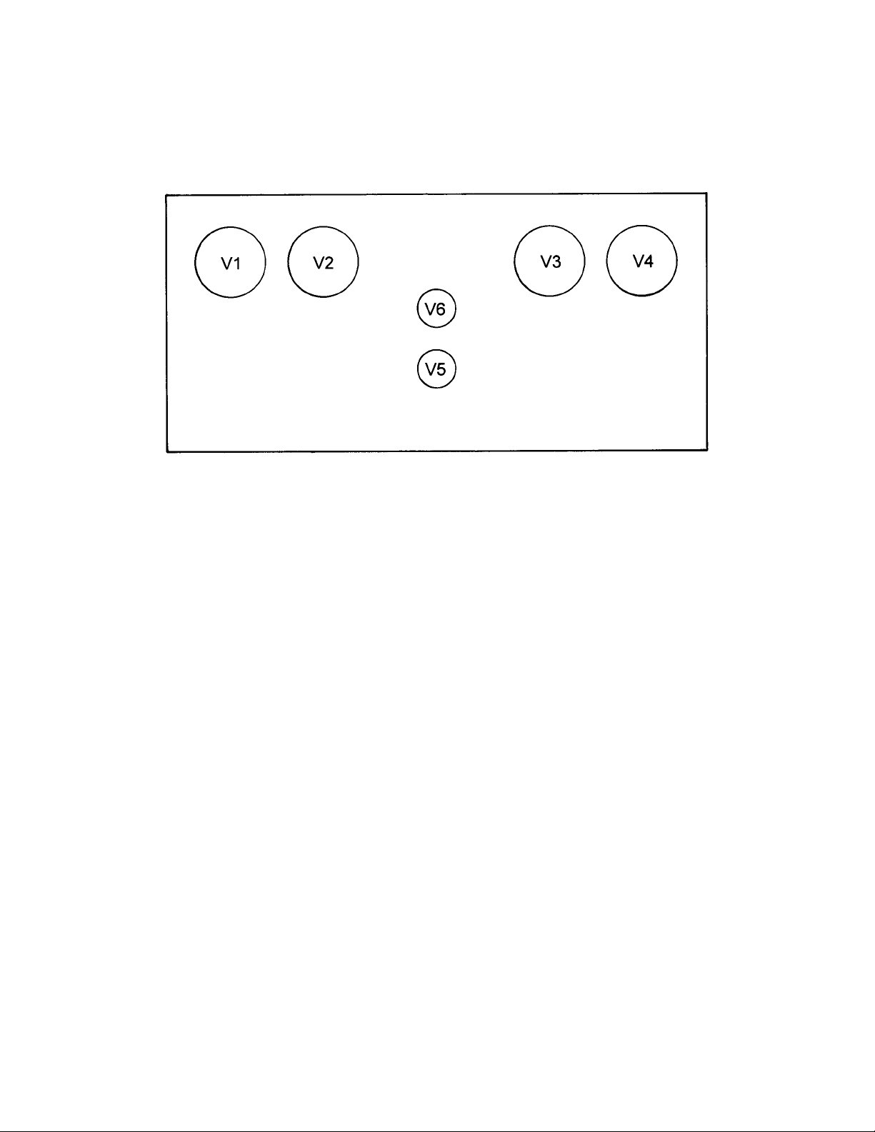
V1 – V4 = 7591A V5 = 12AX7 V6 = 12AT7
After replacing the tubes, attach the top cover with the four Philips screws. Do not over
tighten the screws!
Note: Make sure the ventilation holes face the front panel.
Push the back panel in and tighten the four Philips screws. Do not over tighten the screws!
If the 7591A output tubes have been replaced, following the instructions under Bias
Adjustment.
Page 12
12
Fuse Replacement
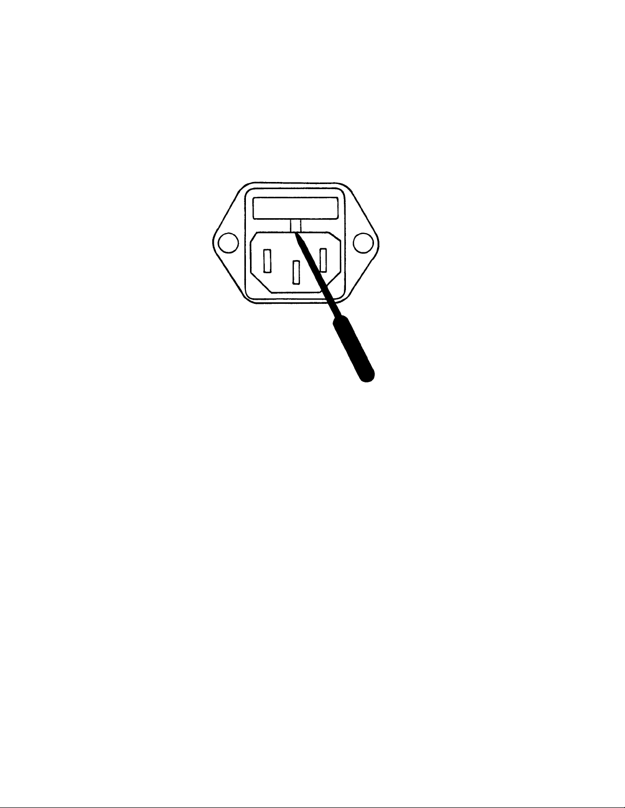
To replace a fuse, see illustration below.
Turn off the Mark 1, and remove the AC connector from the back. Using a small flat bladed
screwdriver, engage the small groove and lever the fuse holder out.
Dispose of the blown fuse, and replace with a 3.5 Amp, 5 X 20 MM SLO-BLO fuse. A spare
fuse is located in the fuse holder clip. If the fuse blows again, there may be a more serious
problem. Contact Customer Service.
Page 13

13
Maintenance
The MARK 1 has a long life ball bearing fan that pulls hot air out and allows cool air to enter
the perforated top and bottom covers. Unfortunately, it also pulls dust laden air in as well.
The dust that builds up inside the MARK 1 will result in certain components overheating,
resulting in premature failure. Just as you must perform periodic cleaning of auto, air
conditioner and heating systems, the MARK 1 also requires cleaning.
To start, follow the instructions for Tube Replacement. The tubes do not need to be removed.
After the top cover has been removed, tighten the four back panel attachment screws. Do
not over tighten the screws!
Carefully set the MARK 1 on its left side (front panel facing you.). Due to its weight, it might
be unstable and require another person to help to prevent it from falling over.
Using a can of compressed air (available at stores that sell computer products.), thoroughly
blow out all accumulated dust inside the unit. Now aim the compressed air at the ventilation
holes on the bottom panel. Using a flashlight, make sure all dust has been removed from the
circuit boards and wiring.
Depending upon the amount of accumulated dust, it might require two or three cans of
compressed air. Be sure to read the instructions on the cans before using.
DANGER! Failure to remove dust can result in a fire!
Reassemble the Mark 1. Make sure that the ventilation holes face the front panel.
Page 14

14
Troubleshooting
Noise is the most common problem in audio systems. Tubes often produce metallic “clicks”
that can be heard through the speakers as they warm up. This is normal, as the metal
elements expand as they heat up. Once the amplifier has reached normal operating
temperature, the noise will disappear.
Other noise problems are hum. Hum can be caused by poor cable connections, a broken
shield in a cable, or cables and audio equipment that are too close to sources of powerful AC
magnetic radiation. Televisions and CRT computer monitors are an example. Simply moving
the equipment further away often cures the problem. Always keep AC cords and signal
cables far apart to minimize hum pickup.
One source of hum is caused by “ground loops”. Ground loops are caused by circulating AC
currents between different pieces of audio equipment via the cable shields. The best way to
avoid ground loops is to plug all of your audio equipment into a “power strip” that has multiple
grounded AC receptacles.
If this fails to resolve the problem, a wire can be attached to the ground screw located on the
back of the Mark 1, and the other end attached to a metal cold water pipe.
Page 15

15
Specifications
POWER OUTPUT, per channel
Tetrode 30 Watts
U/L 24 Watts
FREQUENCY RESPONSE – 1 W
Tetrode ±0, -0.5dB 16Hz – 85kHz
±3.0dB 5Hz – 155kHz
U/L ±0, -0.5dB 16Hz – 55kHz
±3.0dB 5Hz – 135kHz
THD + NOISE - 1 W (unweighted) 0.04% @ 8Ω
THD + NOISE - Maximum Power (unweighted) 0.34% @ 8Ω
CLIPPING POINT – 1% THD + Noise
Tetrode 34 Watts @ 8Ω
U/L 26 Watts @ 8Ω
INPUT SENSITIVITY – 1kHz
1 Watt 0.212Vrms
30 Watts 1.1 Vrms
INPUT IMPEDANCE 100kΩ
POWER CONSUMPTION 210 Watts
TUBE COMPLEMENT 1 – 12AX7, 1 – 12AT7, 4 – 7591A
AC INPUT VOLTAGE 120 VAC, 60Hz
DIMENSIONS 17.625 “ W X 6” H X 16” D
NET WEIGHT 50 Lbs.
Page 16

16
Maintenance Log
Page 17

17
Warranty
Limited Warranty
This product has been manufactured under the highest standards of quality. WWW.VACUUMTUBEAMPS.COM,
LLC Warrants this product to be free of manufacturing defects, subject to the conditions hereinafter set forth, for
a period of two (2) years from the date of shipment. Vacuum tubes are Warranted for 90 days only.
Any defective parts will be replaced free of charge, excluding shipping and handling.
Conditions and Limitations
This Warranty is subject to the following conditions and limitations. The Warranty is void if the product is used
for commercial, business, trade or industrial use; damage caused by accident; abuse; unreasonable use or
neglect; failure to provide timely maintenance in accordance with the instruction manual; modifications to the
product; damage resulting from failure to follow instructions in accordance with the instruction manual; damage
resulting from unauthorized repairs; a product in which the serial number has been altered or removed; damage
caused by power brownouts or surges; acts of God; acts of domestic or foreign terrorism; damage caused
during shipping (claims must be presented to the carrier); products used for non-audio applications.
This Warranty is limited to the original purchaser, and is non-transferable.
Remedy
If a product requires Warranty service, the purchaser must first contact WWW.VACUUMTUBEAMPS.COM via
email, fax or postal mail describing the problem, and will be issued a return authorization number. Products
must be returned in the original shipping box, carefully packaged and insured, at the purchaser’s expense.
Products returned without authorization will be rejected. The product will be repaired without charge for
parts (except tubes that are more than 90 days old), or labor. The product will be returned to the purchaser via
prepaid, insured shipping. This constitutes the owners sole remedy.
Products authorized for Warranty service must be sent to:
Michael A. Burrows
T/A WWW.VACUUMTUBEAMPS.COM, LLC
7851 Sir Topas Drive
Warrenton, VA 20186-8613
Miscellaneous
ANY IMPLIED WARRANTIES RELATING TO THE ABOVE PRODUCT SHALL BE LIMITED TO THE
DURATION OF THIS WARRANTY. THIS WARRANTY DOES NOT EXTEND TO ANY INCIDENTAL OR
CONSEQUENTIAL COSTS OR DAMAGES TO THE PURCHASER. Some states do not allow limitations on
how long an implied warranty lasts or an exclusion or limitation of incidental or consequential damages, so the
above limitations or exclusions may not apply to you. This Warranty gives you specific legal rights, and you may
also have other rights which vary from state to state.
WWW.VACUUMTUBEAMPS.COM, LLC reserves the right to make design changes, and changes in
specifications without obligations or liability to previous purchasers.
Page 18

18
 Loading...