

Page 1

vSync924 & 1624i User Guide © vSync DVR December 2007
Rev A. December 2007
Specifications and content are subject to change without notice.
Page 2

vSync924 & 1624i User Guide © vSync DVR December 2007
TABLE OF CONTENTS
1. Introduction............................................................................................................... ..7
1.1. Overview........................................................................................... ..................7
1.2. Summary of the Specifications of VSync924i & 1624i ......................................9
1.3. Packing List ......................................................................................................10
2. Product Description ................................................................................................. 11
2-1. Front Panel..................... ..... ... .. ...... .. ... ..... ... ... ..... ... .. ...... .. ...... .. ... ..... ... ... ..... ... ..11
2-2. Rear Panel ..... ..... ... .. ...... .. ...... .. ... ..... ... ..... ... ... ..... ... ..... ... .. ...... .. ...... .. ... ..... ... .....13
2-3. Remote Controller....................... ... ..... ... .. ...... .. ...... .. ... ..... ... ..... ... ... ..... ... ..... ... ..15
2-3-1. Alphabet Input with Remote Controller ............................................16
3. Getting Started – Setting Up the DVR ....................................... .............................17
3-1. Setup – Main Screen ............................. ........................................ ..................17
3-2. Setup – Live ............................. ........................................ ................................18
3-3. Setup – Recording Mode............................................ .....................................19
3-3-1. Motion Zone Set Up.............................................................................21
3-3-2. Record Schedule.................................................................................21
3-4. Setup – Device Mode.......................... ........................................ .....................23
3-4-1. ALARM-OUT......................... ................................................................24
3-4-2. PTZ Control............................................................................. .............25
3-4-3. SPOT-OUT .................................................................................... ........26
3-5. Setup – System Mode......................................................................................27
3-6. Setup – Security Mode.....................................................................................30
3-7. Setup – Network Mode.................................... ........................................ ........31
3-7-1. Ports......................... ........................................... ..................................33
3-7-2. Network Types............................. ........................................................33
3-8. Setup - Storage Mode......................................................................................35
3-9. Saving Setup.................................................. .. ...... .. ...... .. ... ..... ... ..... ... ... ..... ... ..36
4. Local Viewing............................................................................................ ................37
4-1. Live Window................................................... ..... ... .. ...... .. ...... .. ... ..... ... ..... ... ... ..37
4-2. SEARCH Window ............................................ ... ..... ... ..... ... ... ..... ... ..... ... .. ...... ..39
4-3. Play mode ........................................ ... ..... ... ... ..... ... ..... ... .. ...... .. ...... .. ... ..... ... .....44
4-4. PTZ Control...................................................... ... ..... ... ... ..... ... ..... ... .. ...... .. ...... ..45
Rev A. December 2007
Specifications and content are subject to change without notice.
2
Page 3

vSync924 & 1624i User Guide © vSync DVR December 2007
5. Archiving Video vi a USB or CD-RW.................................. .....................................46
5-1. Capturing images or video............... ... ... ..... ... .. ...... .. ... ..... ... ... .. ...... .. ... ..... ... ... ..46
5-2. Transferring still images or video onto USB or CD-RW......................... .........47
6. Firmware Upgrade....................................................................................................50
6-1. Preparing USB memory with upgrade firmware..............................................50
7. Network Client - Remote Monitoring and Playback ................................ .............51
8. Remote Setup Using Embedded Web-Server of vSync924i & 1624i..................52
Rev A. December 2007
Specifications and content are subject to change without notice.
3
Page 4

vSync924 & 1624i User Guide © vSync DVR December 2007
CAUTION
z THIS PRODUCT HAS MULTIPLE-RATED VOLTAGES (110V AND 220V). MAKE SURE TO SET THE
VOLTAGE SELECTION SWITCH AT THE REAR PANEL TO THE PROPER VOLTAGE LEVEL OF YOUR
REGION.
z THIS PRODUCT USES A LITHIUM BATTERY. THERE IS RISK OF EXPLOSION IF THE BATTERY ON THE
MAIN BOARD IS INSTALLED INCORRECTLY. DISPOSE OF USED BATTERIES ACCORDING TO
INSTRUCTIONS.
z THIS EQUIPMENT AND ALL COMMUNICATION WIRING IS INTENDED FOR INDOOR USE.
z TO REDUCE THE RISK OF FIRE OR ELECTRIC SHOCK, DO NOT EXPOSE THE UNIT TO RAIN OR
MOISTURE.
Rack Mount Instructions
A) Elevated Operating Ambience - If installed in a closed or multi-unit rack assembly, the operating ambient
temperature of the rack environment may be greater than room ambient . Therefore, consideration should be
given to installing the equipment in an environment compatible with the maximum a mbient temperature (Tma )
specified by the manufacturer.
B) Reduced Air Flow - Installation of the equipment in a rack should be such that the amount of air flow
required for safe operation of the equipment is not compromised.
C) Mechanical Loading - Mounting of the equipment in the ra ck should be such that a hazardous condition is
not achieved due to uneven mechanical loading.
D) Circuit Overloading - Consideration should be given to the connection of the equipment to the supply
circuit and the effect that overloading of the circuits might have on overcurrent protection and supply wiring.
Appropriate consideration of equipment nameplate ratings should be used when addressing this concern.
E) Reliable Earthing - Reliable grounding of rack-mounted equipment should be maintained. Particular
attention should be given to supply connections other than direct connections to the branc h circuit (e.g. use
of power strips)."
Rev A. December 2007
Specifications and content are subject to change without notice.
4
Page 5
vSync924 & 1624i User Guide © vSync DVR December 2007
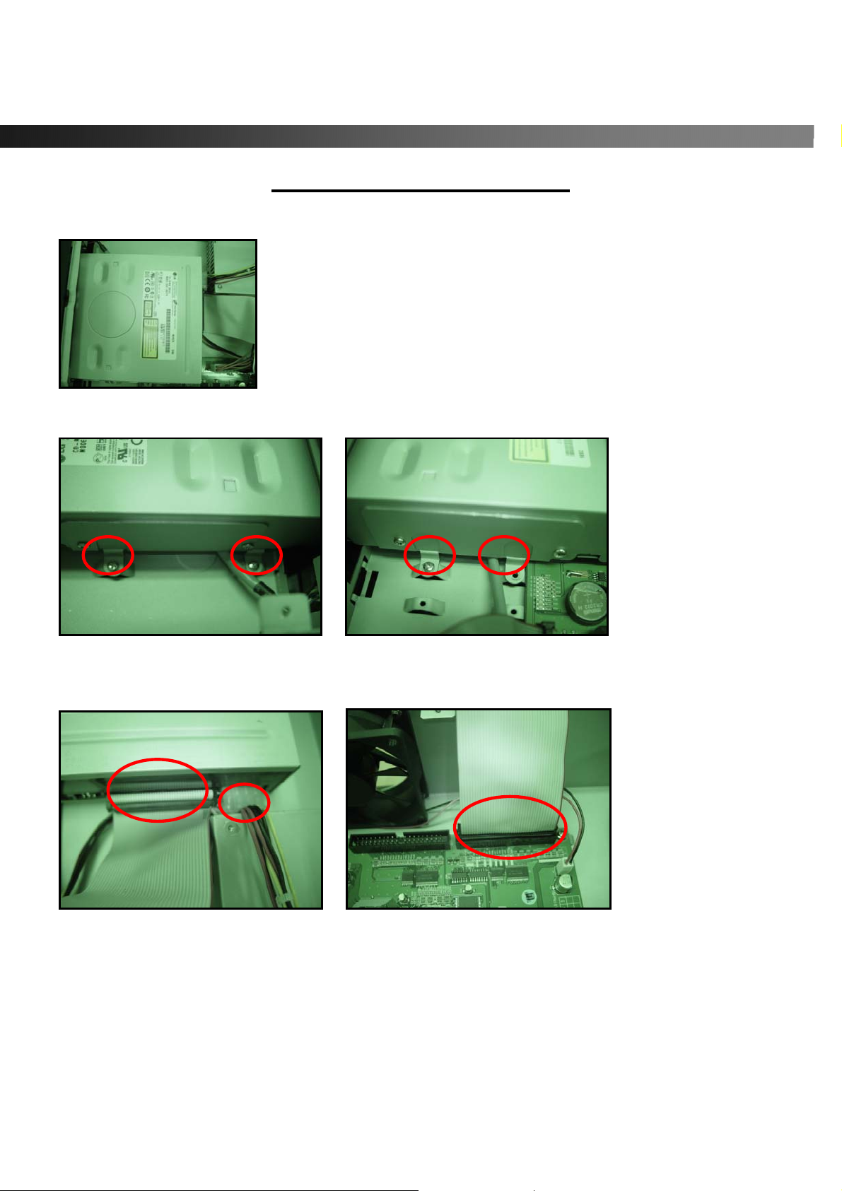
CD-RW Installation Guide
1. Open the top cover of vSync DVR set and Install the CD-RW inside the DVR.
2. Fasten the screws on both side of CD-RW as indicated in red circle below.
3. Connect the IDE CD-RW 40pin cable and Power cable to the point o n both CD-RW and Main board as
indicated in red circles below. Set the CD-RW jumper setting as “MASTER”
Compatible CD-RW model
Sony CRX230EE or contact the vSync DVR distributor for other models.
Rev A. December 2007
Specifications and content are subject to change without notice.
5
Page 6

vSync924 & 1624i User Guide © vSync DVR December 2007
HDD Installation Guide
1. Mount the bracket to the hard disk using the supplied HDD mounting bracket screws.
2. Connect the supplied IDE HDD 80pin cable and Power cable to the hard disk and mount the hard dis k
to the unit using the supplied HDD screws.
3. HDD JUMPER SETTING
ST
1
HDD = MASTER
nd
HDD = SLAVE
2
IDE HDD CABLE CONNECTION ORDER
BLUE: MAIN BOARD
WHITE: SLAVE HDD
BLACK: MASTER HDD
Rev A. December 2007
Specifications and content are subject to change without notice.
6
Page 7
vSync924 & 1624i User Guide © vSync DVR December 2007
1. Introduction
1.1. Overview
● Triplex MPEG-4 9/16 Channel DVR with Real-Time Live Display and Simultaneous Play Back.
● vSync924i & 1624i, (vSync924i Nine channel model & vSync1624i Sixteen channel model).
● vSync924i & 1624i features powerful embedded RTOS (Real Time Operating System).
● MPEG-4 video codec (video encoder/decoder), delivers uncompromised performance providing high
compression plus high quality video images.
● vSync924i & 1624i increases the days of recording between overwrite periods while improving the
quality of video images. Full triplex capability ensures uninterrupted recording.
● vSync DVR supports simultaneous:
1. Video Recording
2. Live Video Monitoring up to 80 cameras
• Locally via video outputs.
• Remotely via vSync network client software and viSync Central Monitoring Softwar e.
3. Play Back or File archiving via USB 2.0 port and CD-RW.
Or
1. Video Recording
2. Remote Playback via vSync network client software and viSync CMS.
● vSync software also allows the administrator to remotely connect to, monitor, and manage multiple
networked DVRs. The vSync software logs the operation, motion, and alarm statuses of sites throughout
the day for later analysis. The vSync software lets you search based on time or event, record on a
remote PC, and retrieve video clips from remote sites.
● vSync software supports additional powerful remote control features,
z Powerful Live Connection & Customizable Camera Layout up to 80 channels,
z Embedded Web Server (Remote Configuration of all vSync DVRs)
z Full Duplex Bi-directional Audio (2-way Communication)
z Recording on Client PC, Alarm/Motion Indicator, eMAP, Digital Live Zoom
z Remote Relay Control, Remote PTZ Control.
Rev A. December 2007
7
Specifications and content are subject to change without notice.
Page 8

vSync924 & 1624i User Guide © vSync DVR December 2007
● NAFS (Network-Attached File Server) file systems provide a cluster-base d network-attached file server
which offers a high level of performance, reliability, and availability.
- Ex. Prevention of data loss and corruption in the event of a power failure.
● Multiplexing operation.
● State-of-the-art live monitoring and playback both locally and remotely.
● Individual channel recording and playback with different frame rates.
● Hidden Channel Mode on selected channels provides extra privacy and uninterrupted recording.
● Embedded Web-Viewer provides direct access using IP address or DDNS address in Internet Explorer.
● Multi-site management via network: up to 80 cameras.
- Supported by vSync network client software and viSync CMS.
- Remote live monitoring & recording , playback, backup, PTZF control & Presets, relay sensor contro l,
eMAP, Digital Live Zoom, and 2-way communication.
- Remote DVR management via embedded Web-Browser for easy adjustments.
- Mobile phone & PDA viewing integration.
● Network via LAN, DDNS, DHCP, ADSL (Dynamic and Static IP addresses).
● Full duplex 4 Channel G.711 synchronized audio recording and Bi-directional Audio Communication.
● Built-in Quad Multiplexer provides sequential or quad display on all or selected channels.
● User-friendly setup menu with simplified G.U.I.(Graphic User Interface).
● Easy to schedule weekly recording plans.
● Motion detection – Use the 30x24 grid to define motion zones for each camera.
● Internal Pan/Tilt/Zoom/Focus controller.
● Easy operation via front panel and optional remote controller .
● Increased security by user name and password verification.
● Video loss detection.
● Backup - Still-images or AVI data onto USB storage device, internal CD-RW, or Network.
● USB port for JPEG/MPEG data backup and software upgrade using USB storage device.
● Still image capture and review as JPEG format.
● Variety of Hard Driv e Siz es - up to 2TB internally (500GB HDD X 4) for long-term recording.
● Multi-Languages - User can easily select language from Setup menu.
● Various Video Outputs - VGA(800x600 24-Bit Color), TV-Out, S-Video, SPOT-Out, Loop-Out.
Rev A. December 2007
8
Specifications and content are subject to change without notice.
Page 9
vSync924 & 1624i User Guide © vSync DVR December 2007
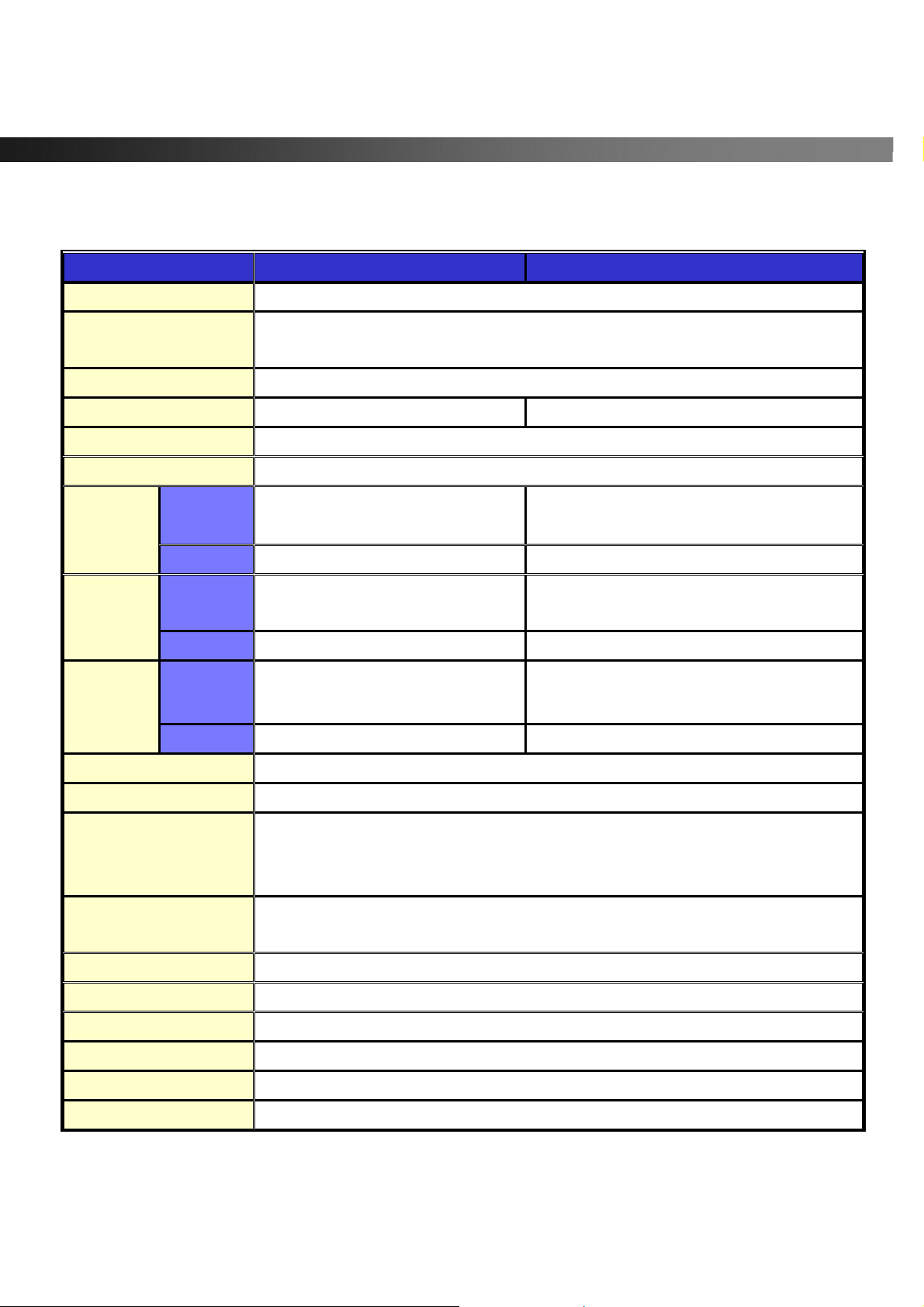
1.2. Summary of the Specifications of VSync924i & 1624i
Item Description Remarks
Operating System RTOS in f i rmware
Video/Audio
Compression
Triplex Function Record/Playback/Live Streaming or Record/USB archive/Live Streaming
Video Input Format NTSC/PAL Auto-Detection
Video Input 9 Ch (16 Ch) In
Video Output
Display
Frame Rate
Recording
Frame Rate
(Quad)
Recording
Frame Rate
(Full)
Record Modes Continuous/Motion/Schedule/Sensor/Manual
NTSC
PAL
NTSC
PAL
NTSC
PAL
1Ch VGA, 1 Ch BNC (Composite), 1Ch Spot-Out. 9Ch(16Ch) Loop-Out, 1 Ch S-VIDEO
270(480) frames/sec Real-Time
(Hidden Display Function)
225(400)frames/sec 25 frames/sec/Ch
240 frames/sec
(Hidden Record Function)
200 frames/sec 352x288 resolution
60 frame /sec (total)
50 frame /sec (total) 704 x 576 resolution
MPEG-4(video) /
G.711-PCM (audio)
9 Ch(16 Ch) x 30 frames/sec
352x240 resolution
704 x 480 resolution
Record Quality Network/Standard/High/Superior/Ultra
NTSC : 704 x 480(1 CH), 352x 240(Quad)
Resolution
Audio Input/Output
Channel
Alarm In/Alarm Output 9/16 Alarm Input (NC/NO selectable) / 8 Relay Output
HDD 3.5”, IDE type9 (IDE ATA133 Type), Min 80GB up to 4 IDE HDDs
CD-RW Optional CD-RW
Motion Detection Motion-Triggered Recording
Search Mode Date/Time/Event Search
Playback Speed 1x, 2x, 4x, 8x
2-way communication(Bi-Directional) Audio via network
Rev A. December 2007
Specifications and content are subject to change without notice.
PAL : 704 x 576(1 CH), 352 x 288(Quad)
Supports CIF, Half D1 & Full D1
4 Ch Input/1 Ch Output
9
Page 10
vSync924 & 1624i User Guide © vSync DVR December 2007
Serial Interface
USB Archiving (still images in JPEG format, video in AVI format), Firmware upgrade
Upgrade Method USB 2.0 Port or Web-Browser
PTZ Control
Network Interface LAN(10/100Base-T), Static, DHCP, PPPoE, and DDNS
Live Connection & Customizable Camera Layout up to 80 channels
Client PC S/W
( vSync )
Remote Playback
Power 110/220V, 50/60Hz
Embedded Web Server (Remote Configuration of all vSync DVRs)
Full Duplex Bi-directional Audio (2-way Communication)
Recording on Client PC, Alarm/Motion Indicator, eMAP, Digital Live Zoom
1 RS-232C (POS text inserter connection)
1 RS-422/485 (for PTZ control)
Local &
Remote Relay Control, Remote PTZ Control
Via vSync Client Software
vSync Client Software
Window2000/XP/Vista
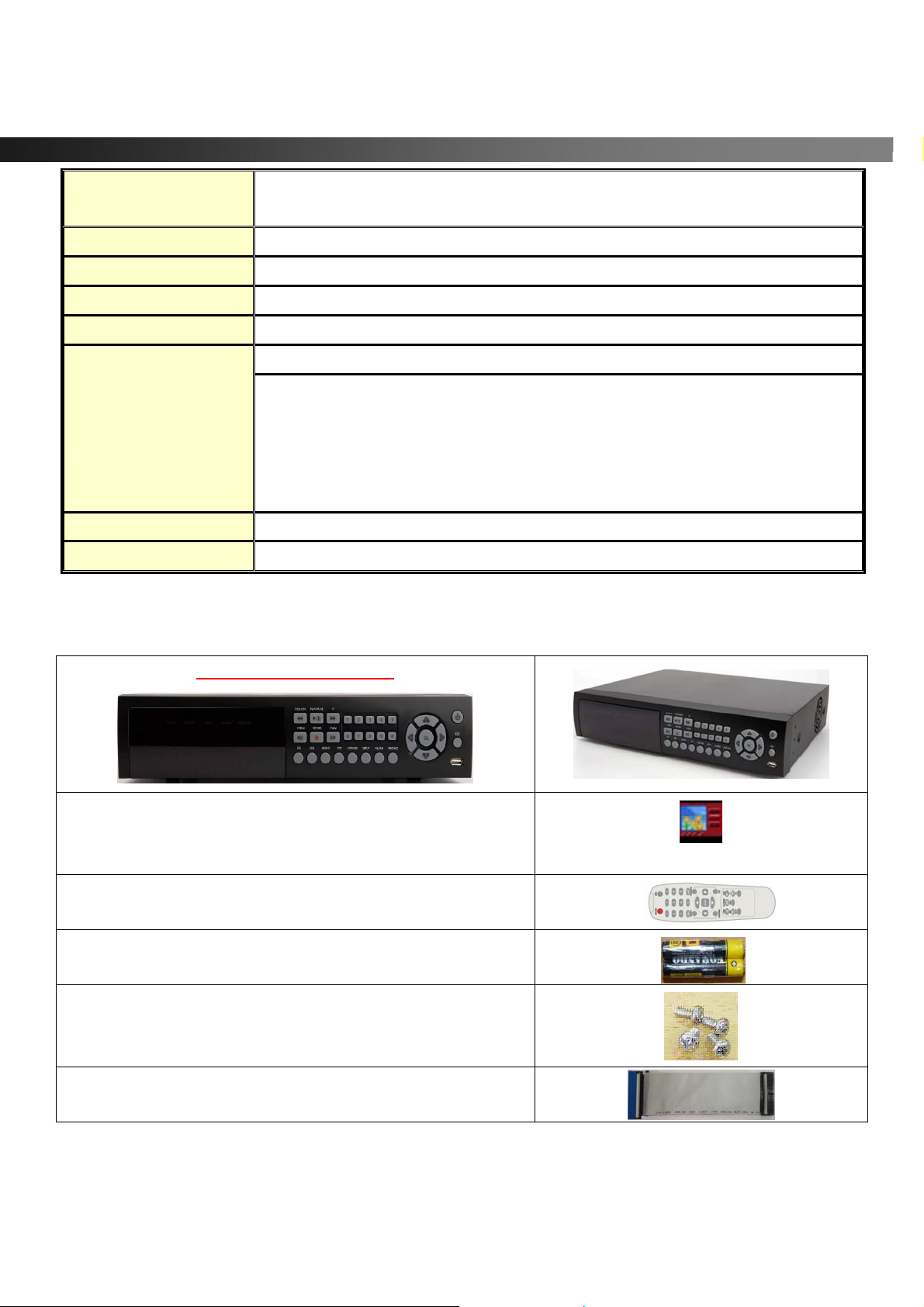
1.3. Packing List
vSync924i or vSync1624i
Support CD includes:
vSync Network Client,
Utility Programs, Manual(s).
Infrared Remote Control
Batteries
Screws for mounting HDD.
(Preinstalled when unit is shipped with HDD)
HDD connection cables (2 ea).
(Preinstalled when unit is shipped with HDD(s))
Vsync.exe
Rev A. December 2007
Specifications and content are subject to change without notice.
10
Page 11
vSync924 & 1624i User Guide © vSync DVR December 2007
HDD Mounting Brackets (2ea)
(Preinstalled when unit is shipped with HDD(s))
2. Product Description
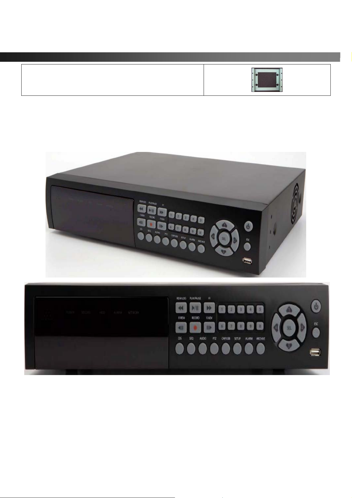
2-1. Front Panel
Figure 2.1. Front Panel of vSync924i & 1624i
Rev A. December 2007
Specifications and content are subject to change without notice.
11
Page 12

vSync924 & 1624i User Guide © vSync DVR December 2007
Table 2.1.1. Indication LEDs
Name Description
NETWORK
HDD
REC
ALARM
POWER
Name Description
POWER
DIS
SEQ
AUDIO
PTZ
SETUP
LED illuminates when system is accessing the hard disk drive.
LED illuminates when recording is enabled.
LED illuminates when alarm sensor(s) is/are triggered or detects video motion.
(Alarm sensor(s) and/or video motion detection must be configured first).
LED illuminates when clients connect through vSync software via network port.
LED illuminates when the DVR unit is on.
Table 2.1.2. Buttons on the Front panel
Power ON/OFF. (Prompts for password before shutdown) Configure settings for
power down in the SECURITY Setup Menu. The default password is “1111”.
Press to select full, quad, 9 or 16 split-screens in live display mode.
Press to start auto-sequencing in 1 Ch, 4 Ch, 9 Ch, or 16 Ch display modes.
Press to select audio mode.
Disable or Mute all 4 channels or selected channels only.
Press to initiate PTZ control
Press to launch SETUP menu.
ALARM
ARCHIVE
CAP/USB
REW/LOG
F/REW
F/ADV
FF
PLAY/PAUSE
REC
Rev A. December 2007
Press to silence alarm operation.
Press to review the ARCHIVE LIST in live display mode.
Press to take a snapshot, or capture still images (JPEG format), during live or
playback modes.
(During Playback) Press to rewind video footage at 1x, 2x, 4x, and 8x speeds or
to see the LOG LIST in live display mode.
Jump/Step backward.
In playback mode, the playback position reverses/jumps backwards 60 seconds.
Jump/Step forward.
In playback mode, the playback position moves forward 60 seconds.
(From Playback Mode)
Pressing fast forward advances footage at 1x, 2x, 4x, and 8x speeds.
From Live Display Mode: Press to enter SEARCH menu.
From Playback Mode: Press to play or pause video.
Press to start or stop manual recording.
12
Specifications and content are subject to change without notice.
Page 13
vSync924 & 1624i User Guide © vSync DVR December 2007
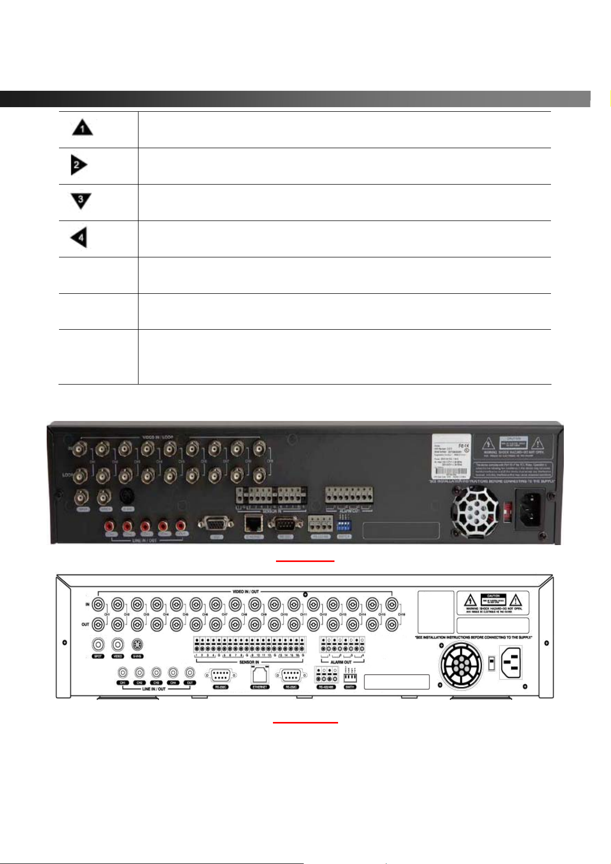
Press to scroll up in the menu or to change values in setup mode.
UP
(Also used as the number 1 when entering a password.)
Press to scroll right in the menu or to change values in setup mode.
RIGHT
DOWN
LEFT
SEL
ESC
USB Port
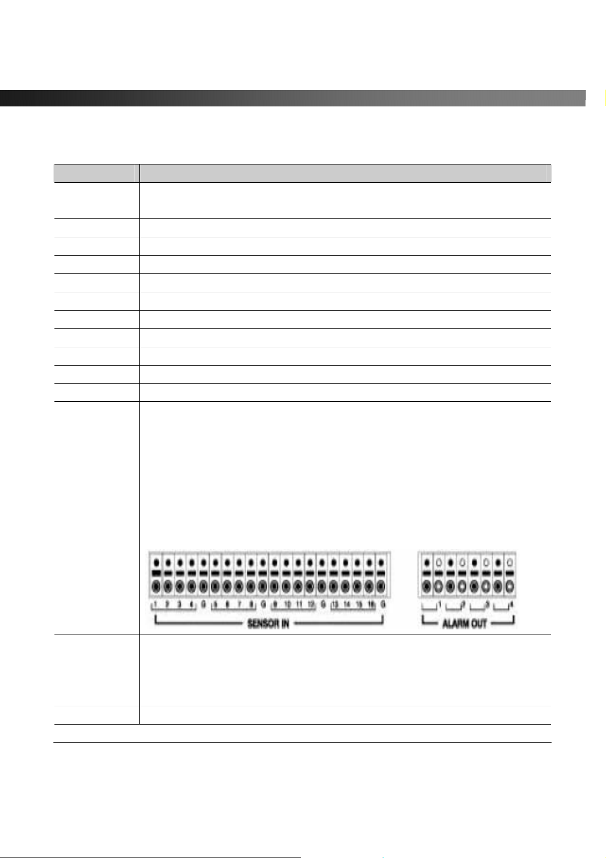
2-2. Rear Panel
(Also used as the number 2 when entering a password.)
Press to scroll down in the menu or to change values in setup mode.
(Also used as the number 3 when entering a password.)
Press to move left in the menu or to change values in setup mode.
(Also used as the number 4 when entering a password.)
(Surrounded by the direction control keys)
Pressing selects desired menu item or saves setup values in menus.
Press for temporary storage of the changed value or to return to the previous
menu screen.
The USB Port is located on front panel’s bottom right corner.
This USB port is used to archive recordings onto a USB storage device or upgrade
firmware with a USB storage device.
vSync924i
vSync1624i
Figure 2.2. Rear Panel
Rev A. December 2007
Specifications and content are subject to change without notice.
13
Page 14
vSync924 & 1624i User Guide © vSync DVR December 2007
Table 2.2.1. Connectors and Switches on Rear Panel
Name Function
VIDEO IN
VIDEO OUT
SPOT
VIDEO
S-VHS
VGA
AUDIO IN
AUDIO OUT
RS-232
LAN
RS-485/422
SENSOR IN
9/16 BNC connectors for video input.
Connect camera output to Video-in (NTSC/PAL)
9/16 BNC connectors for video output. (Loop-Out)
Composite video output for spot monitoring. (Built-in Quad Multiplexer)
Composite video output in NTSC or PAL format
S-Video output
Connect to a VGA monitor 15-pin connector
4 RCA connectors for audio input.
1 RCA connector for audio output.
POS text inserter connection
RJ-45 connector for Ethernet connection.
For Pan/Tilt/Zoom control.
Connector for external alarm sensor/contact devices alerts the vSync DVR and
allows it to respond to events. 9/16 sensors can be connected to the DVR sensor
1~9/16 dedicated to Video Channel 1~9/16 correspondingly.
Connect 2 wires to activate a sensor input to the Terminal Block on the rear panel
of the vSync DVR. A ground wire from the external device to the unit ensures that
the ground reference voltage is identical. This line connects to the Terminal Block
G input.
ALARM OUT
POWER
Rev A. December 2007
8 (PGM) connectors for alarm device connection.
Provides simple On/Off switching using relay (not included).
0.5A/125V or 1A/30V. The relay is open when not triggered. The relay can be close
by either a motion or a sensor input, only if enabled in the Recording Setup menu.
Connector for AC115/220V power cable.
14
Specifications and content are subject to change without notice.
Page 15
vSync924 & 1624i User Guide © vSync DVR December 2007
DIP SWITCHES
TEST
RSV
VGA
PAL
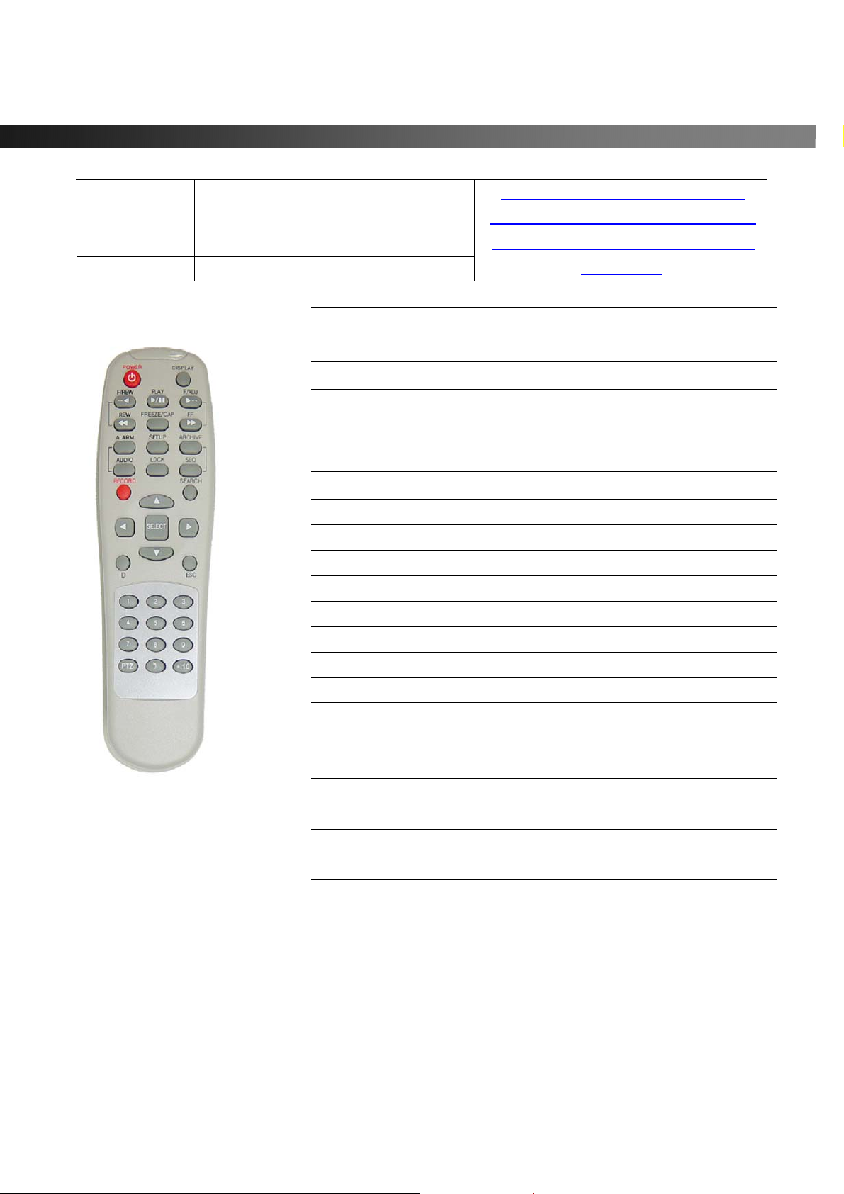
2-3. Remote Controller
For futur e use.
Reserved.
Turn ON for VGA monitor use.
Turn ON for PAL use.
POWER Power On/Off
DISPLAY Displays Full, Quad or 9/16 Ch. Split View
F/REW Jump 60 Seconds Backwards
PLAY Play/Pause
F/ADV Jump 60 Seconds Forwards
FREEZE/CAP Freeze/Screen Capture
FF Fast Forward
ALARM Silence/Mute Alarm Operation
SETUP Setup Menu
ARCHIVE Displays Archive List
AUDIO Disable/Mute or Highlighted Channel Only
LOCK Locks front panel and remote for all functions
SEQ Sequences Full or Quad View
RECORD Manual Recording
SEARCH Search Menu Screen
DIRECTION
SELECT
ID DVR ID (ID Button + DVR ID number)
ESC Escape
Direction or Number 1 to 4
Enter
When you change the position of the
switch, reboot the DVR to apply the new
setting. When VGA is on, Video-Out will
be disabled!
Rev A. December 2007
Specifications and content are subject to change without notice.
PTZ PTZ Menu Screen
NUMBER Channel 1 to 9
CH 10->press +10 and number 0
+10 CH 11->press +10 and number 1
CH 12->press +10 and number 2
CH 13->press +10 and number 3
CH 14->press +10 and number 4
CH 15->press +10 and number 5
CH 16->press +10 and number 6
15
Page 16
vSync924 & 1624i User Guide © vSync DVR December 2007
2-3-1. Alphabet Input with Remote Controller
The Numeric keys of the remote co ntroller can be used to enter letters when alphabet input is needed in
parameter setting. The scheme follows the same pattern of a telephone keypad.
For example, press the number “2” continuously to change the input value to “2, A, B, C, a, b, c, 2… “.
This mode is useful for assigning channel names, DDNS, or ADSL configuration information.
The following table details the assignment of letters to the numeric keypad.
Table 2.3.1.1. Alphabet Input with Numeric Keypad of the Remote Controller
Numeric Key Input Values
1 1
2 A, B, C, a, b, c, 2
3 D, E, F, d, e, f, 3
4 G, H, I, g, h, i, 4
5 J, K, L, j, k, l, 5
6 M, N, O, m, n, o, 6
7 P, Q, R, S, p, q, r, s, 7
8 T, U, V, t, u, v, 8
9 W, X, Y, Z, w, x, y, z, 9
Rev A. December 2007
Specifications and content are subject to change without notice.
16
Page 17
vSync924 & 1624i User Guide © vSync DVR December 2007
3. Getting Started – Setting Up the DVR
The following sections detail the initial setup of the vSync DVR.
3-1. Setup – Main Screen
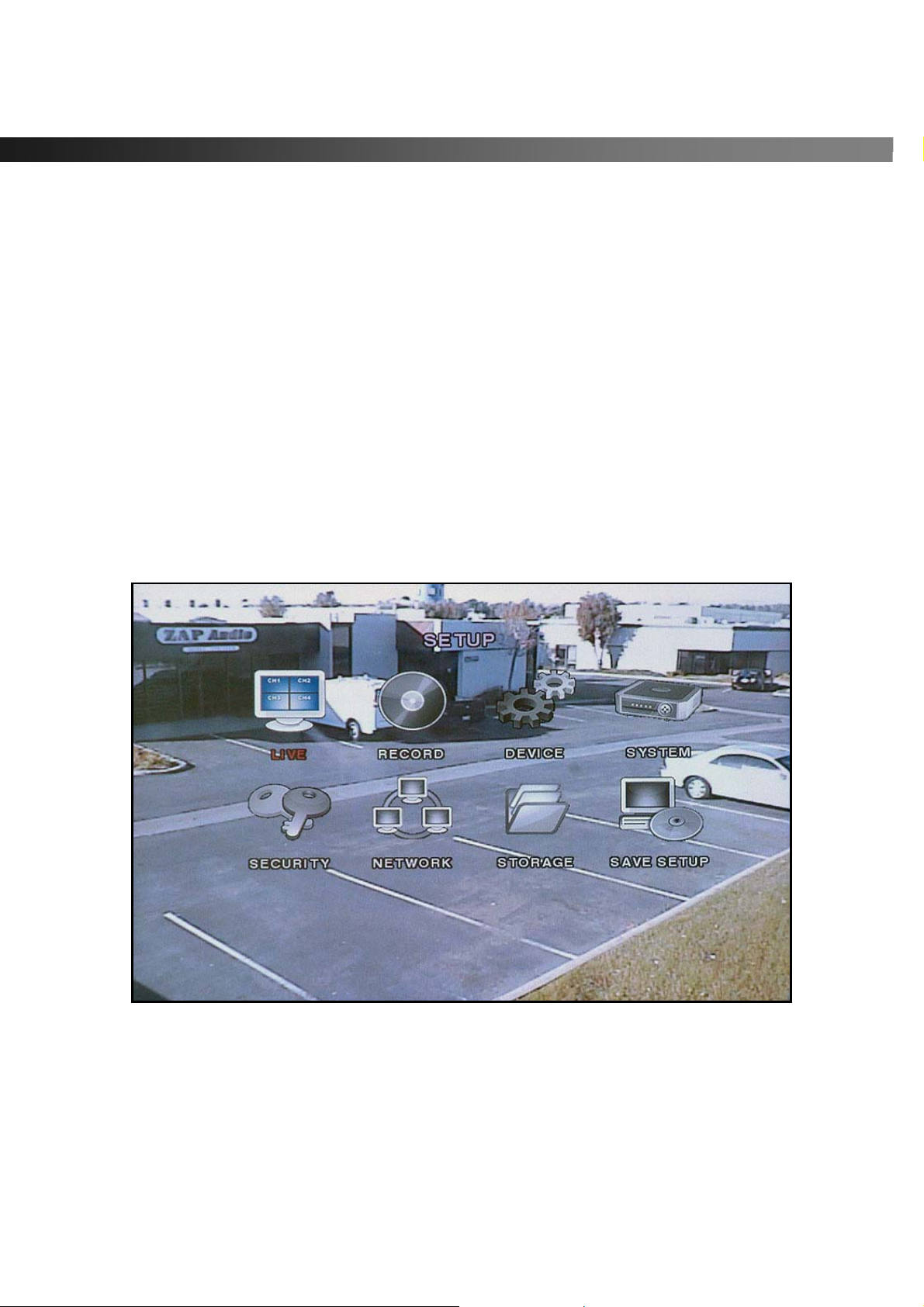
Pressing the Setup button prompts a user for entry of a password. The default password is “1111”.
Input the default password by pressing the Up button 4 times, followed by the SELECT button.
(We recommend that you protect your DVR system by assigning a new password. Refer to section
3.6 for instructions.)
After assigning a new password, enter it by using the direction arrow keys (representing 1, 2, 3, & 4) or
using the keypad, and then press the SEL button for entering into the Setup menu shown in Figure 3.1.1.
Navigate through the menu icons using the directional buttons and press the SELECT button to enter into
sub-category menus.
Figure 3.1.1. Setup menu screen
Rev A. December 2007
Specifications and content are subject to change without notice.
17
Page 18

vSync924 & 1624i User Guide © vSync DVR December 2007
3-2. Setup – Live
- Used for setting up the live display mode.
Navigate through menu items using the Up/Down buttons. Change the values using the Left/Right buttons.
Figure 3.2.1. Live mode setup screen
Table 3.2.1. Menu items in LIVE mode setup
Item Description
OSD
SEQUENCE
SEQ-DWELL TIME
OSD CONTRAST
CHANNEL
DISPLAY
BRIGHTNESS
CONTRAST
HUE
SATURATION
Rev A. December 2007
Specifications and content are subject to change without notice.
Enables/disables on-screen-display.
Enables/disables sequential video channels display in full screen mode.
Sets dwell time for each channel in sequential display mode.
Sets the contrast level of On Screen Display (OSD)
Selects channel to apply settings.
Enables/disables Hidden Channel Mode on selected channel.
Brightness value for the specified channel.
Contrast value for the specified channel.
Hue value for the specified channel.
Saturation value for the specified channel.
18
Page 19
vSync924 & 1624i User Guide © vSync DVR December 2007
3-3. Setup – Recording Mode
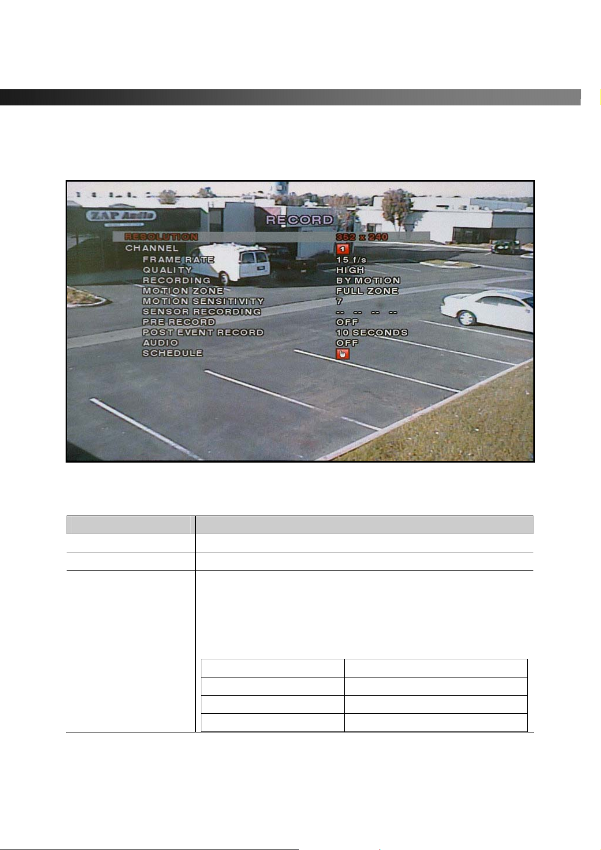
- Controls video recording attributes
Navigate through the menu items using Up/Down buttons. Change values using Left/Right buttons.
Figure 3.3.1. Recording mode setup screen
Table 3.3.1. Menu Items in Record Mode Setup
Menu item Description
RESOLUTION
CHANNEL
FRAME RATE
Configures resolution as 704x480, 704x240, or 352x240(NTSC).
Selects channel to apply settings.
Configures the frame rate for selected channel.
Frame Rate and Recording Resolution are interdependent.
The 9/16 channel frame rate sum may not exceed the maximum
frame rate supported by the resolution.
The following table shows the maximum frame rate for NTSC video.
Resolution Max. Frame Rate
320x240 240 FPS
704x240 120 FPS
704x480 60FPS
Rev A. December 2007
Specifications and content are subject to change without notice.
19
Page 20
vSync924 & 1624i User Guide © vSync DVR December 2007
QUALITY
Configures the recording quality for selected channel.
Network, Standard, High, Super, Ultra.
Video quality is the best on “Ultra” setting (Network quality is
designed for very low upload bandwidth conditions (i.e. weak WAN
connections).
RECORDING
MOTION ZONE
MOTION SENSITIV I T Y
SENSOR RECORDING
PRE RECORD
POST EVENT RECORD
AUDIO
SCHEDULE
Assigns the recording method for a channel:
Disable, Continuous, Motion, Sensor, or Schedule.
Sets full zone or partial zone.
Sets motion detection sensitivity for selected channel from 1 to 9.
(9 is the most sensi tive setting.)
Configures Alarm/Sensor Inputs for triggered recording. There are
16 sensors total (9 for vSync924i). A maximum of 4 sensor/alarm
Inputs may be assigned to an individual channel.
Enables/disables pre-event/pre-alarm recording.
Pre-event/pre-alarm recording is 5 sec. Only i-frames are recorded.
Set the length of time for post-event/post-alarm recording video.
Configurable by channel from 1 to 30 seconds.
Enables/disables audio by channel.
There are 4 channels of audio inputs and a single audio output.
Configures recording schedules.
Launches new menu as shown in Figure 3.3.3.
Rev A. December 2007
Specifications and content are subject to change without notice.
20
Page 21
vSync924 & 1624i User Guide © vSync DVR December 2007
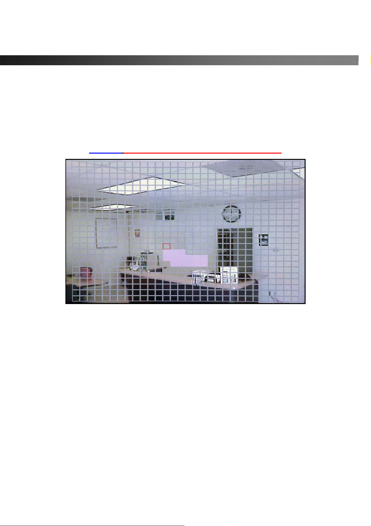
3-3-1. Motion Zone set up
By selecting Partial Zone, users can define motion zones within a screen area, as shown in Figure 3.3.1.
Move each rectangular zone around using the four direction key buttons . Press the SELECT button to save
the defined rectangular region as part of the motion zon e. Upon saving, the defined rectangular blocks will
change color.
Important: Only selected zones will trigger motion recording.
Figure 3.3.1. Motion Zone selection scre e n
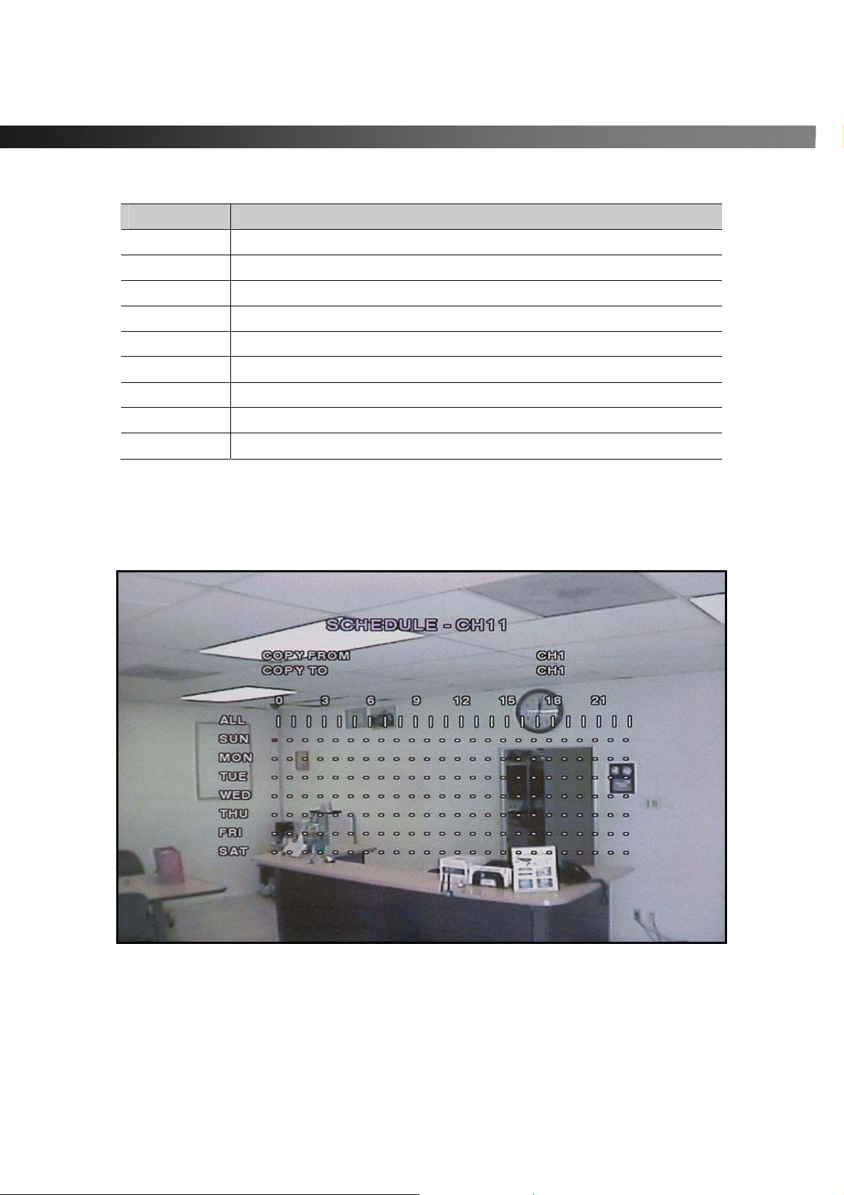
3-3-2. Record Schedule
- Records video based on a defined schedule.
The following table (3.3.3) defines button functions within this menu.
Navigate through menu items using the Up/Down buttons. Change the values using the Left/Right buttons.
Each vertical bar “ | ” corresponds to one hour. See Figure 3.3.3 for a menu example.
Rules:
1. Choosing ALL, vSync DVR globally applies the schedule to all time periods and channels.
2. Within a selected channel, a recording mode applies to the entire time period for the specific
channel.
3. Within a selected time period, when highlighting one of the vertical bars “ | ”, the selected recording
mode applies to all channels.
Rev A. December 2007
Specifications and content are subject to change without notice.
21
Page 22
vSync924 & 1624i User Guide © vSync DVR December 2007
Table 3.3.3. Button Functions in Recording Time Scheduling Mode
Button Function
REW
F/REW
PLAY/PAUSE
FF
UP
RIGHT
DOWN
LEFT
SEL
Copying of a Schedule:
The following picture shows the copying of a schedule from Ch 1 to Ch 2 (useful for copying the schedule of
one channel to another channel).
Use to set Continuous recording mode.
Use to Disable recording setting.
Use to enable Motion detection triggered recording.
Use to enable Sensor triggered recording
Move up in menu item.
Move right in menu item.
Move down in menu item.
Move left in menu item.
Exit from scheduling mode.
Figure 3.3.3. Recording Schedule Set-up Screen
Rev A. December 2007
Specifications and content are subject to change without notice.
22
Page 23
vSync924 & 1624i User Guide © vSync DVR December 2007
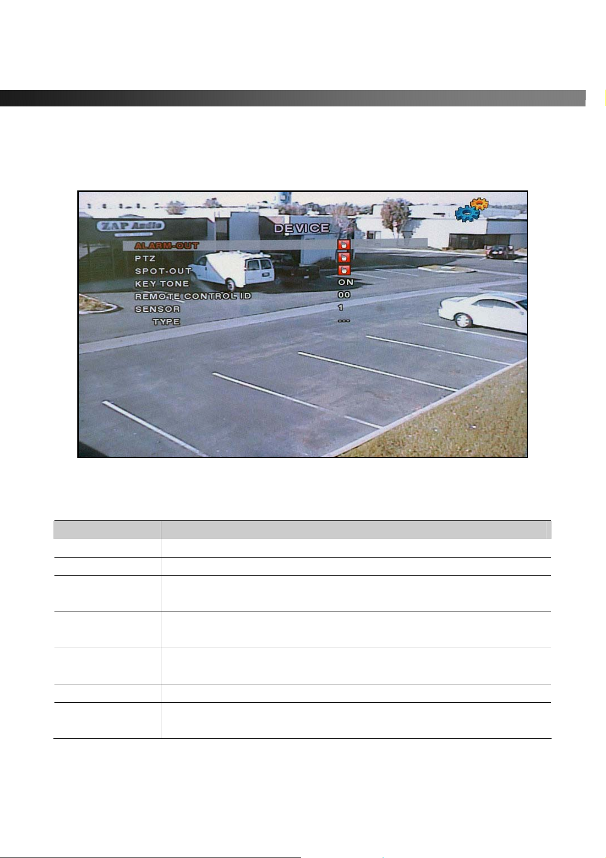
3-4. Setup – Device Mode
- Configures values for device settings.
Navigate through menu items using the Up/Down buttons. Change the values using the Left/Right buttons.
Figure 3.4.1. Device mode setup screen
Table 3.4.1. Menu items in Device Setup screen
Item Description
ALARM-OUT
PTZ
SPOT-OUT
KEY TONE
REMOTE
CONTROL ID
SENSOR
TYPE
Rev A. December 2007
Set the sensor, motion, video loss, and options for each alarm.
Sets the camera’s pan speed, number, type and ID
Configures the spot monitor output type (sequential or quad), and channel
select.
Enable/disable key tone audio. The vSync DVR beeps for e ach keystroke on
the front panel or remote controller.
Enter an ID for the remote controller. ID can range from 00 to 99, and is
convenient when using multiple vSync DVR.
Select a sensor from 1 to 16.
Set the style of contact/alarm input for a specified sensor number.
Choose None, N/O (normally open), and N/C (normally closed).
23
Specifications and content are subject to change without notice.
Page 24
vSync924 & 1624i User Guide © vSync DVR December 2007
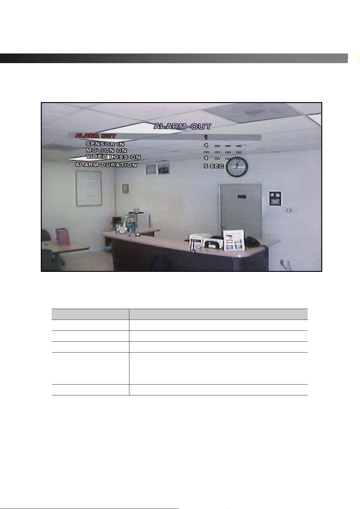
3-4-1. ALARM-OUT
Figure 3.4.1.1. Al arm -out set up scr ee n
Table 3.4.1.1 Menu Items in ALARM-OUT Setup Screen
Item Description
ALARM OUT
SENSOR IN
MOTION ON
VIDEO LOSS ON
ALARM DURATION
Rev A. December 2007
Specifications and content are subject to change without notice.
Select alarm out puts from 1 to 8.
Enable up to 4 sensors out of a total of 16.
Enable up to 4 cameras out of a total of 16.
Enable up to 4 cameras out of 16 cameras.
(From Multi Channel the video loss occurs simultaneously, one
initial channel is notified with e-mail address in network setup)
Sets the alarm duration from 1 to 60 seconds.
24
Page 25
vSync924 & 1624i User Guide © vSync DVR December 2007
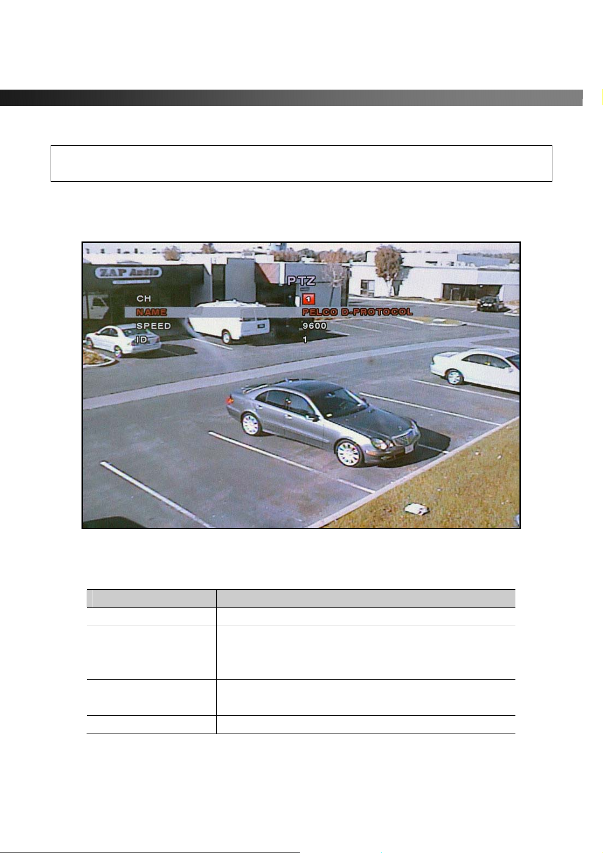
3-4-2. PTZ Control
To control the PTZ functions of a camera, connect the controller to the RS-485 port.
For speed dome cameras that supports RS-485, connect them directly to the RS-485 port.
For cameras using RS-232C, a Signal Converter (RS-485 to RS-232C) is needed (not included).
From the PTZ Control setting setup menu, select/set the protocol for the camera man ufacturer you wish to
control. If the camera uses a specific camera ID, select the camera ID by using the Left or Right buttons.
Figure 3.4.2.1. PTZ setup screen
Table 3.4.2.1. Menu item in PTZ Setup screen
Item Description
CH
NAME
SPEED
ID
Rev A. December 2007
Specifications and content are subject to change without notice.
Select the channel number for the PTZ device setup.
Navigate through the list of PTZ cameras (protocol type) by
using the LEFT and RIGHT arrow buttons and make a
selection.
Configure the speed (baud rate) of the RS-485
communication port by using the LEFT and RIGHT buttons.
Program the PTZ address. (0-63)
25
Page 26
vSync924 & 1624i User Guide © vSync DVR December 2007
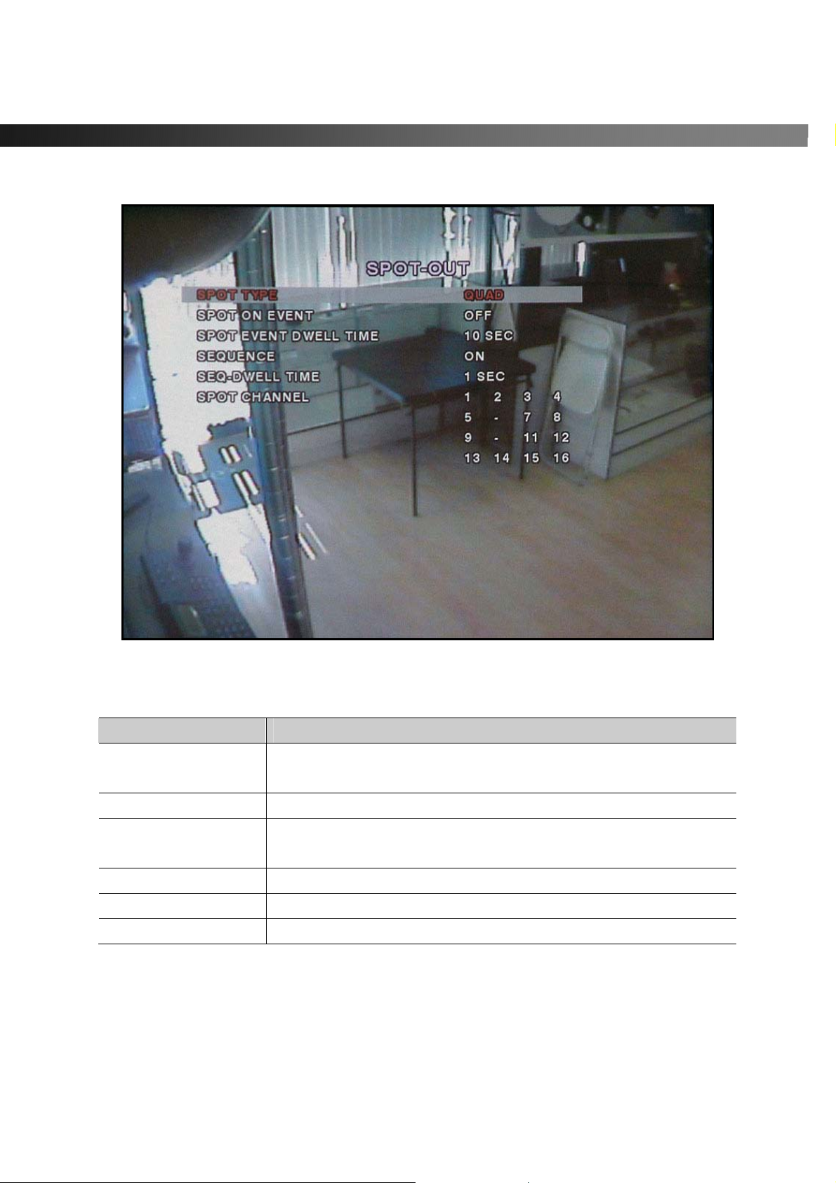
3-4-3. SPOT-OUT
Figure 3.4.3.1 Spot-O ut Setup Screen
Table 3.4.3.1. Menu Items i n SPOT-OUT Setup Screen
Item Description
SPOT TYPE
SPOT ON EVENT
SPOT EVENT
DWELL TIM E
SEQUENCE
SEQ-DWELL TIME
SPOT CHANNEL
Rev A. December 2007
Specifications and content are subject to change without notice.
Configure the display mode, either full or quad view for the spot
monitor out put .
Enable/disable spot monitor upon events.
Set the dwell time for the spot event monitor from 1 to 10 seconds.
Enable/disable SEQ button.
Set the channel sequence dwell time.
Select the channel(s) to display on the Spot Monitor.
26
Page 27
vSync924 & 1624i User Guide © vSync DVR December 2007
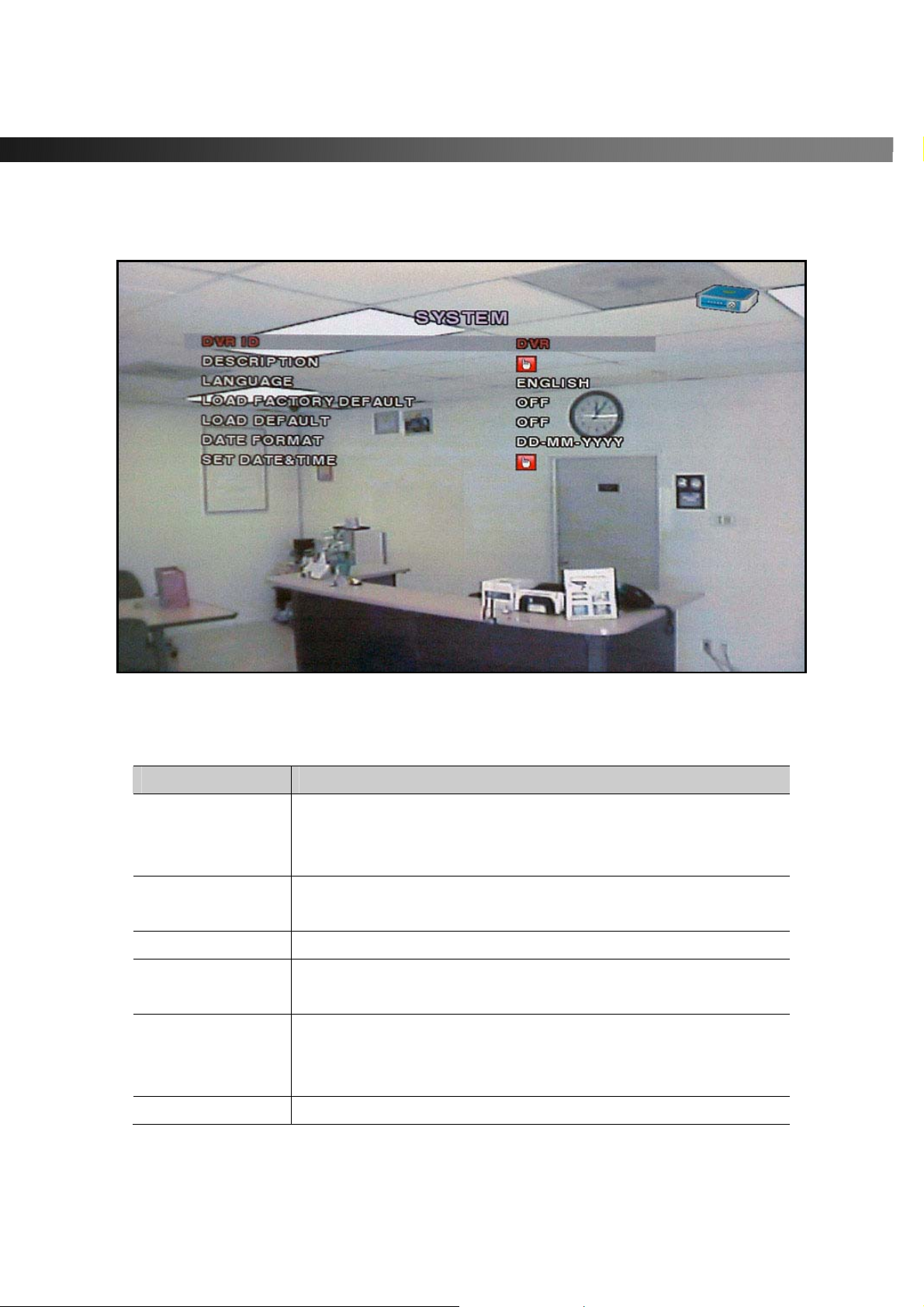
3-5. Setup – System Mode
- Configures system parameters
Navigate through menu items using the Up/Down buttons. Change the values using the Left/Right buttons.
Figure 3.5.1. System Setup Screen
Table 3.5.1. Menu Items in System Setup Screen
Item Description
DVR ID
DESCRIPTION
LANGUAGE
LOAD FACTORY
DEFAULT
LOAD DEFAULT
DATE FORMAT
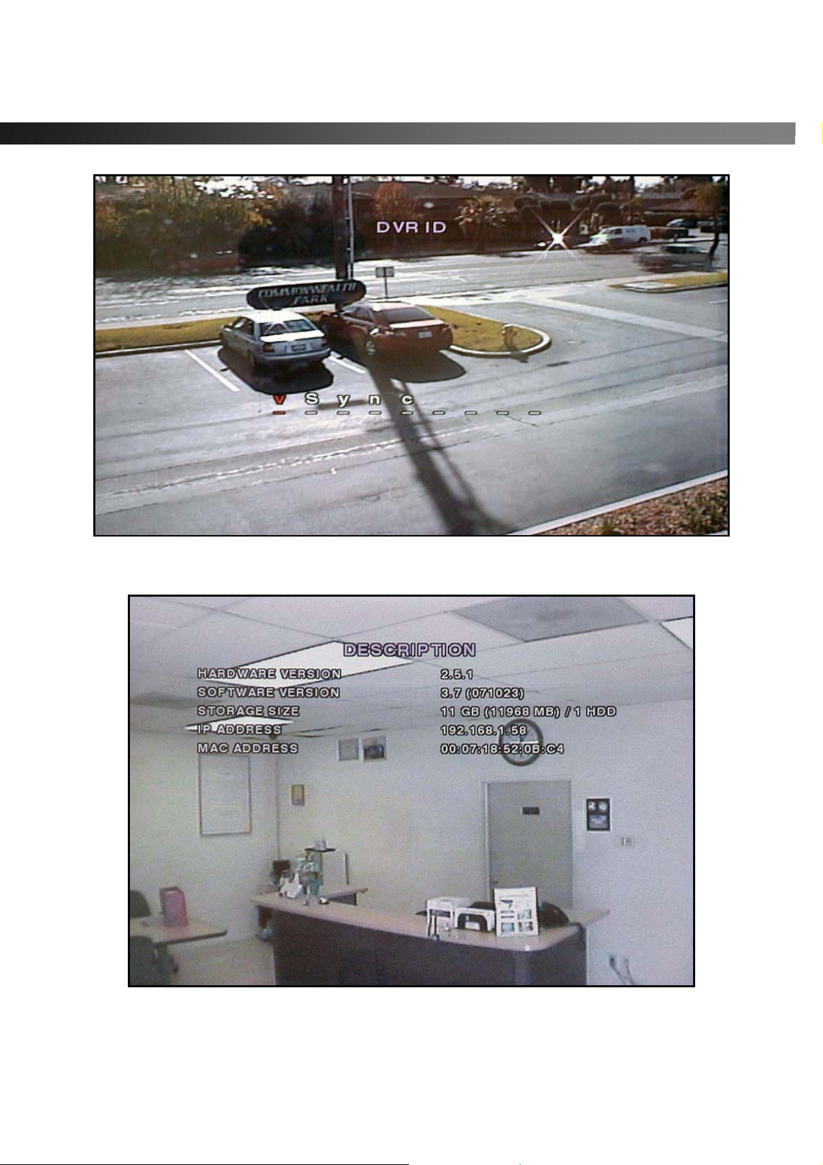
Defines the system name. Navigate through the position for each
alphanumeric character by using the left and right buttons.
Up/down buttons change characters.
Displays system info rmation:
Firmware Version, Storage Size, IP Address, and MAC Address.
Select a language for all OSD (on screen display)
Select OFF or ON. To load default values, choose ON, then press
the SEL button.
Select OFF or ON. ON loads the default values, with the
following exceptions: Password, Date format, DLS setting,
Network parameters, HDD overwrite mode.
Configures the preferred display style for the date and time.
Rev A. December 2007
Specifications and content are subject to change without notice.
27
Page 28
vSync924 & 1624i User Guide © vSync DVR December 2007
Figure 3.5.2. DVR ID Setup Screen
Figure 3.5.3. DVR Information Display Screen
Rev A. December 2007
Specifications and content are subject to change without notice.
28
Page 29
vSync924 & 1624i User Guide © vSync DVR December 2007
SET DATE&TIME
DAYLIGHT
SAVINGS
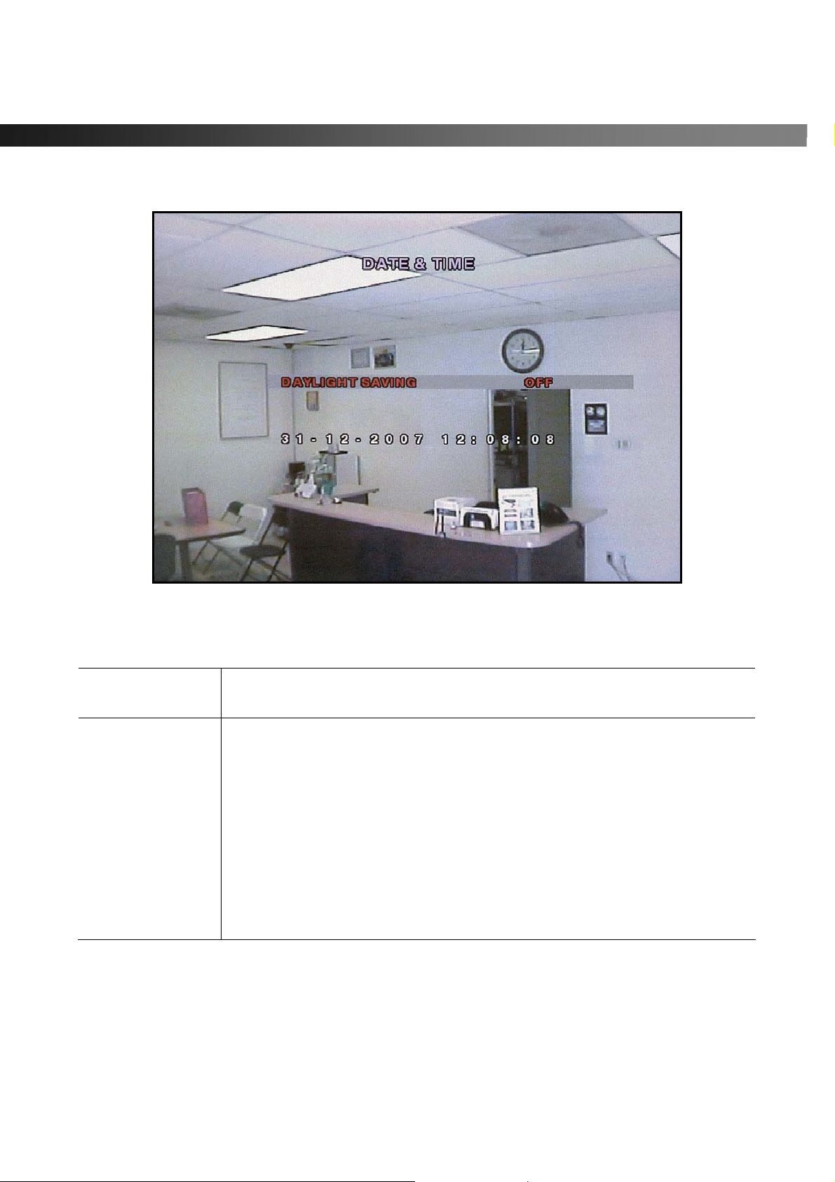
Figure 3.5.4.Set Date & Tim e Setup Screen
Table 3.5.4. Menu Items in Date & Time Setup
Warning! Changing this setting initiates a system reboot. Set date and
time. After changing, press the SEL button and select CONFIRM.
Configures automatic adjustment for Daylight Savings Time.
Use the LEFT or RIGHT buttons to enable/disable.
After selecting ON, move the cursor to the BEGIN (MM/DD/HH) field.
Press the SELECT button to set the DLS start time. Scroll to the END
(MM/DD/HH) field.
Set the DLS stop time by using the UP or DOWN buttons.
CAUTION : PLEASE NOTE TO PREVENT ERRORS
-DLS can’t start from 23:00.
-The BEGIN DATE and END DATE CANNOT be the same.
Rev A. December 2007
Specifications and content are subject to change without notice.
29
Page 30
vSync924 & 1624i User Guide © vSync DVR December 2007
3-6. Setup – Security Mode
- Assign new password and security p arameters here.
Navigate through menu items using the Up/Down buttons. Change the values using the Left/Right buttons.
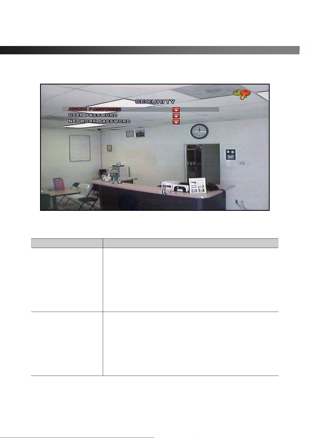
Table 3.6.1. Menu Items i n Se c urity Setup Screen
Item Description
ADMIN PASSWORD
USER PASSWORD
Figure 3.6.1. Security Setup Screen
Sets the administrator password. Once selected, the DVR will
prompt for the current password and new password.
Follow the prompts. The numbers 1, 2, 3 and 4 can be input by using
direction keys UP, RIGHT, DOWN, and LEFT, respectively.
The keypad can be used to input all characters from 0 – 9.
The default password is “1111”.
The Admin Password allows access to all DVR features.
Sets the user password. Once selected, the DVR will prompt for the
current password and new password.
Follow the prompts. The numbers 1, 2, 3 and 4 can be input by using
direction keys UP, RIGHT, DOWN, and LEFT, respectively.
The keypad can be used to input all characters from 0 – 9.
The default password is “1111”.
User has access only for search features.
Rev A. December 2007
Specifications and content are subject to change without notice.
30
Page 31
vSync924 & 1624i User Guide © vSync DVR December 2007
NETWORK PASSWORD
Sets the network client connect password. The DVR prompts for the
entire process of setting up a network password.
The numbers 1, 2, 3 and 4 can be in put by using direction keys UP,
RIGHT, DOWN, and LEFT, respectively.
The keypad can be used to input all characters from 0 – 9.
The default user ID is “root” and the def ault password is “1111”.
3-7. Setup – Network Mode
- Configures network parameters used for remote clien ts that connect to the DVR over a network or other
network features.
Navigate through menu items using the Up/Down buttons. Change the values using the Left/Right buttons.
If you do not understand the following settings, consult your network administrator.
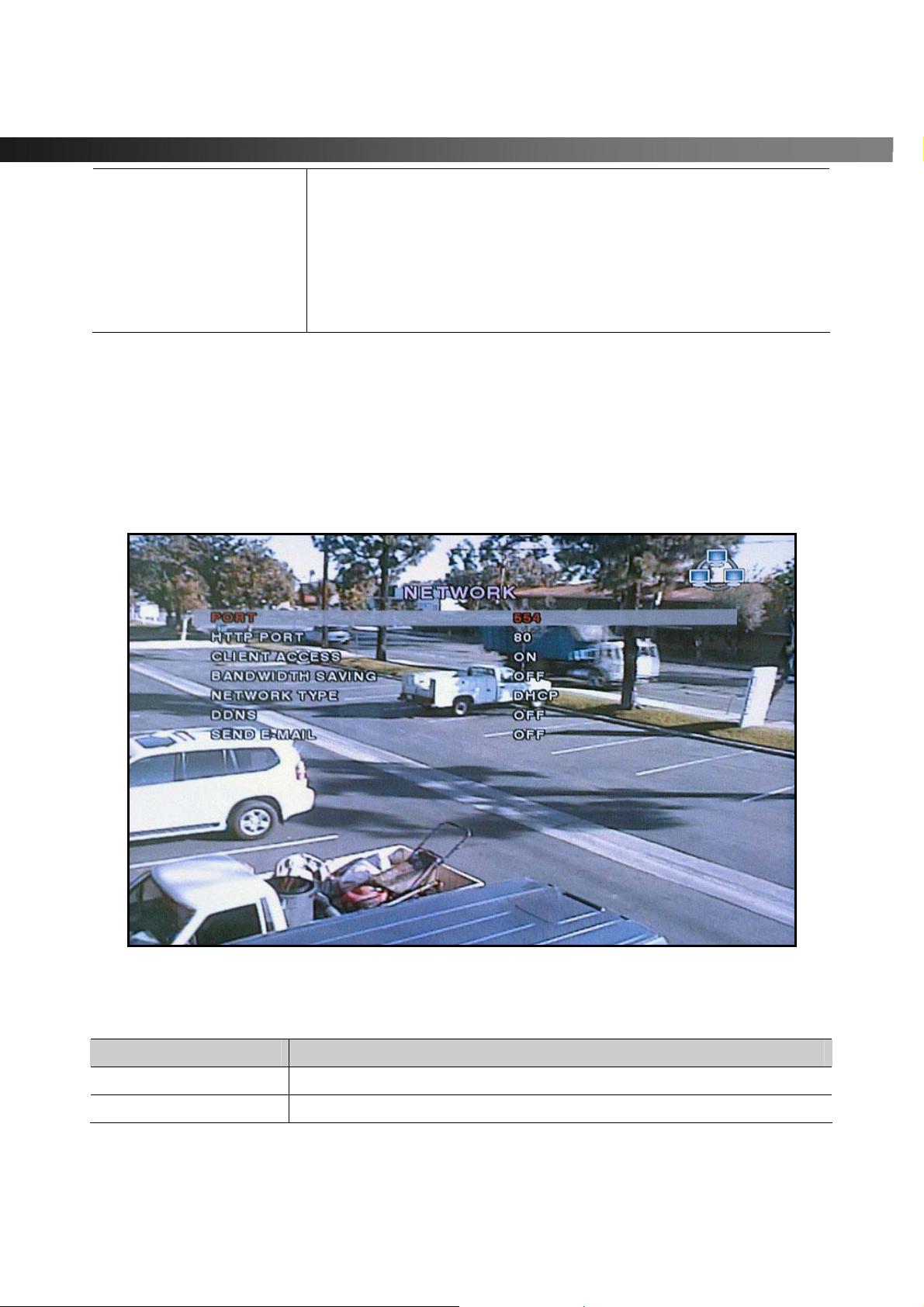
Figure 3.7.1. Network Setup Screen
Table 3.7.1. Menu Items in Network Set-up Setup Screen
Item Description
PORT
HTTP PORT
Rev A. December 2007
Specifications and content are subject to change without notice.
RTSP port number
HTTP Port number
31
Page 32
vSync924 & 1624i User Guide © vSync DVR December 2007
CLIENT ACCESS
Enables/Disables network client access
BANDWIDTH SAVING
NETWORK TYPE
DHCP
IP
GATEWAY
SUBNET MASK
DNS
DDNS
Send E-mail
Enables/Disables key frame transmission only. This feature is useful
when network bandwidth is not enough for live streaming.
Type of network
Enables/Disables DHCP connection (Dynamic IP address)
Static IP address
Gateway IP address
Network Subnet Mask address
DNS server IP address. Valid DNS address is needed for E-mail
transmission and use of DDNS.
Domain name for the DDNS server. DDNS is used to resolve dynamic
IP address by assigning a host name to replace the IP address for the
connection.
Setting this value to “ON” initiates e-mail transmission as follows
through the designated email server. Set to “ON”, and press SEL button
to BEGIN e-mail configura tion.
For use with DHCP (Dynamic IP) servers.
On : 1. “ALARM + IP”
2. “ALARM EVENT”
3. “NOTIFY IP”
Off : alarm = alarm event : capture JPG file and emails
1. Alarm + IP
2. Alarm Event
3. Notify IP
Mail Address
Mail Server Name
ID
Password
Return Address
A combination of “Alarm Event” and “Notify IP”
If an event occurs, the DVR s ends a n email to a specified recipient with
a JPG file of the event.
If the DHCP server assigns a new IP address to vSync DVR, the DVR
sends an email to a specified recipient with the new IP address..
Input the designated recipient’s address.
Enter the name of your SMTP server.
Enter your SMTP server user ID.
Enter your SMTP server password.
Warning: Some incoming e-mail servers block e-mail reception from
unverified return e-mail addresses. Enter a valid e-mail address
associated with the passwords above.
Rev A. December 2007
Specifications and content are subject to change without notice.
32
Page 33
vSync924 & 1624i User Guide © vSync DVR December 2007
3-7-1. Ports
Port-Forwarding for Access from a WAN
When one or more DVRs are connected through a IP sharing device (i.e. rou ter) to a larger netw ork (i .e. the
internet), in order to access each unit from outside the local area network, each device must have a unique
RTSP (Real Time Stream Protocol) and HTTP port number. You must also configure your IP sharing
device for port-forwarding, so that each port, when accessed on the IP sharing device, will forward to the
appropriate DVR’s IP and or MAC address. The port number is listed next to the “Port” menu option in the
Network menu.
If you only plan to access multiple units from within a local area network
the RTSP and HTTP port numbers, unless other IP sharing devices establish in-between the client
and the DVRs.
To access the DVR, you must have the following information:
Table 3.7.1.1 Information Needed for Network Access
When accessing from the same LAN When accessing from outside the LAN
DVR IP Address The router or Gateway IP addresses
(The IP address of the IP sharing device)
RTSP port number RTSP port number
HTTP port number HTTP port number
Username Username
Password Password
3-7-2. Network Types
Configure one of three network types: LAN, DHCP, or ADSL
Each type requires different settings.
, you do not need to change
LAN
To use the LAN option when connecting the D VR to a network, the follow ing information is required. If you
do not have this information, see your network administrator.
Table 3.7.2.1. Network Parameters for LAN
Item Description
IP
GATEWAY
SUBNET MASK
Rev A. December 2007
Specifications and content are subject to change without notice.
The fixed IP address of the DVR
The IP address of the gateway
The subnet mask for the LAN
33
Page 34
vSync924 & 1624i User Guide © vSync DVR December 2007
DHCP
Select DHCP (for Dynamic IP Addressing) to enable this feature. The DHCP server or a router
automatically assigns the unit an IP address and other appropriate TCP/IP settings. After connecting to the
network, view the assigned IP address by selecting DESCRIPTION from the SYSTEM menu.
If the network connection does not offer additional IP addresses , use an IP sharing device to remedy the
issue. Port-Forwarding may be necessary in order to conn ect to this device. Also, if a firewall is deployed in
the IP sharing device, the selected ports must be opened to the outside network. For more information on
Port-Forwarding, see the documentation for your IP sharing device (router) or contact your local authorized
vSync DVR distributor.
ADSL
vSync DVR supports direct PPPoE connections to ADSL modems without a router. The following
information is required. If you do not have this information, contact your network administrator.
Table 3.7.2.2. Network Parameter s for ADSL
Item Description
ID
PASSWORD
The ADSL modem connection must have an RJ-45 jack to connect to the DVR (USB Networking is not
supported).
Sharing an ADSL connection with other devices requires an IP sharing device such as router. In this case,
select LAN as the NETWORK type. Port-forwarding is required in order to access the vSync DVR through a
GATEWAY/Router and/or Firewall. See the documentation for your IP sharing device or contact your
network administrator to learn more about port-forwarding. If your router has QoS (Quality of Service) and
gaming feature, you may want to enable this for the IP address of the DVR . Some ISPs block some ports
commonly used for streaming video. If your ISP blocks the default port, simply change the por t number to an
unblocked port. See the ISP technical support web page for additional help troubleshooting blocked ports.
The user ID for the ADSL connection
The password for the ADSL connection
Rev A. December 2007
Specifications and content are subject to change without notice.
34
Page 35
vSync924 & 1624i User Guide © vSync DVR December 2007
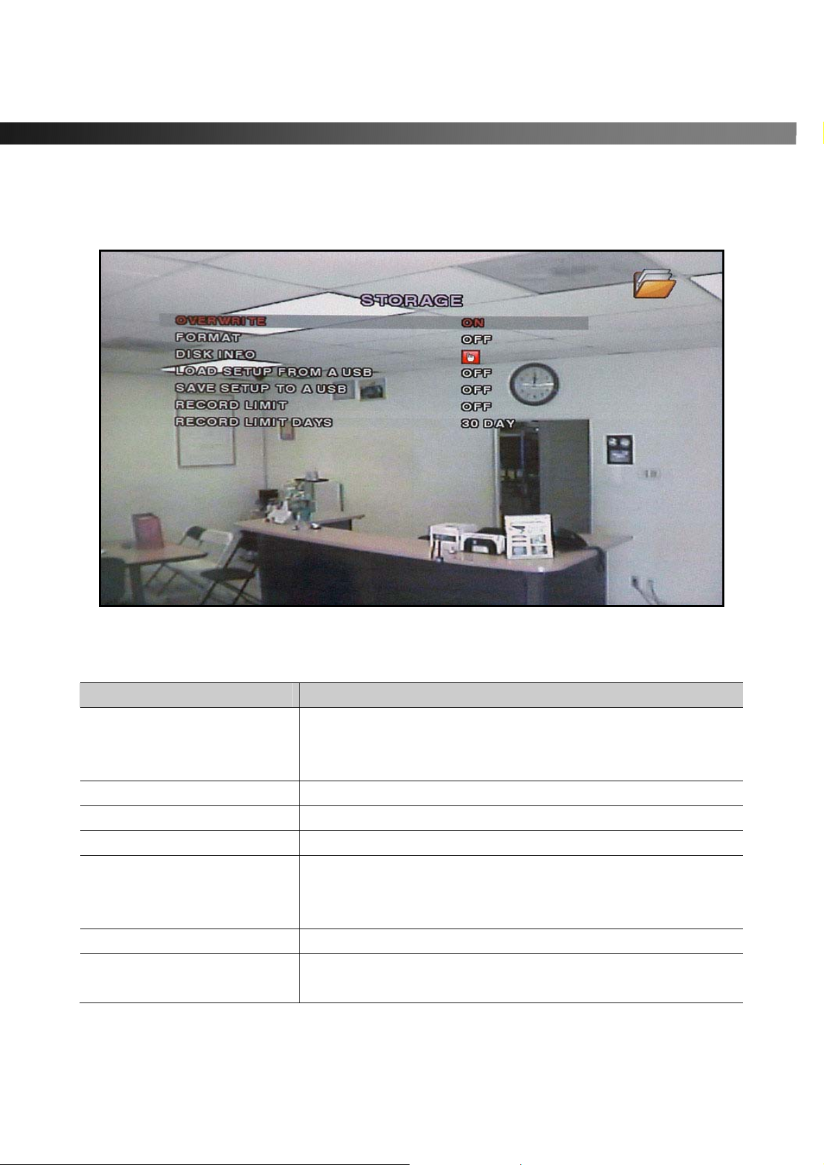
3-8. Setup - Storage Mode
-Configures the hard disk record mode, or initiates a hard disk format.
Navigate through menu items using the Up/Down buttons. Change the values using the Left/Right buttons.
Item Description
OVERWRITE
FORMAT
DISK INFO
LOAD SETUP FROM A USB
SAVE SETUP TO A USB
RECORD LIMIT
RECORD LIMIT DAYS
Figure 3.8.1. Storage Setup Screen
Table 3.8.1. Menus in Storage Setup
When enabled, the DVR will continue recording and overwrite the
oldest existing recorded data once the hard drive is full.
When disabled, recording will stop once the hard drive is full.
Formats the har d disk driv e.
Displays HDD(s) disk information.
Loads DVR setup parameters from the USB memory.
Stores DVR setup values to USB memory.
This feature is useful when cop ying the setup parameters of one
DVR to other DVRs or for building templates.
Turns recording limit on/off for overwrite.
Set number of days for the record limit. Only functions when
“Record Limit” is on.
Rev A. December 2007
Specifications and content are subject to change without notice.
35
Page 36
vSync924 & 1624i User Guide © vSync DVR December 2007
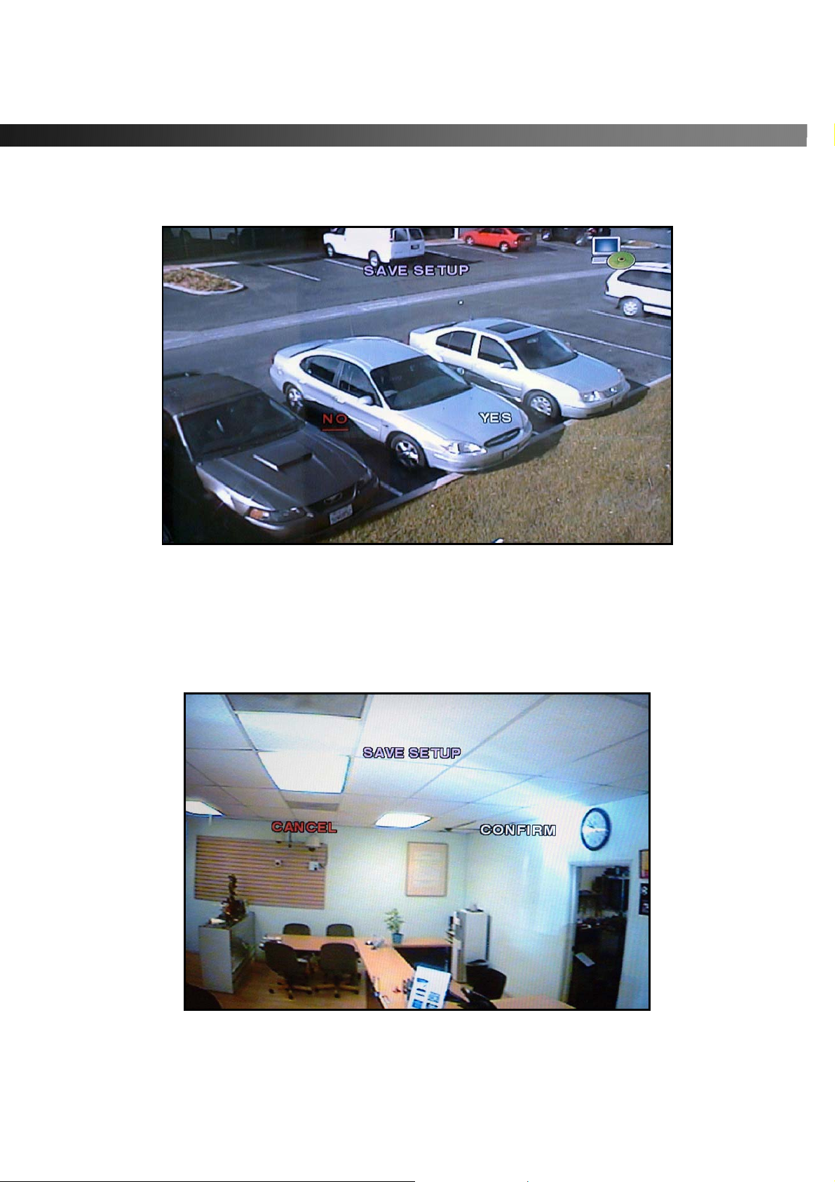
3-9. Saving Setup
To preserve changed setup values, select the SAVE SETUP menu and select YES. Unsaved setup values
will be lost if this step is ignored or not applied properly.
Figure 3.9.1. Save Setup Screen
Certain changes require that the system is restarted in order to take place.
These features will ask for a confirmation and are as follows:
z Load Factory Default, Set Time & Date, Network, Format, Load Setup from a USB
Figure 3.9.2. Save Setup Screen
Rev A. December 2007
Specifications and content are subject to change without notice.
36
Page 37
vSync924 & 1624i User Guide © vSync DVR December 2007
4. Local Viewing
4-1. Live Window
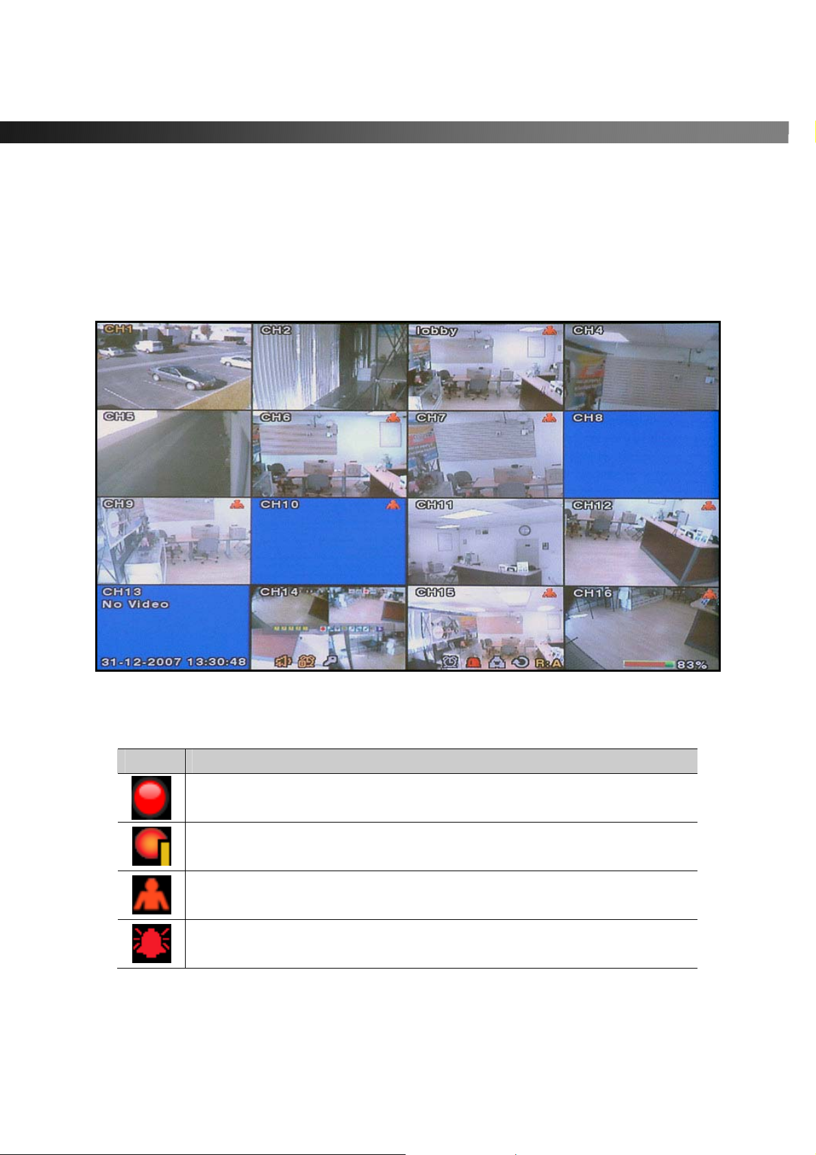
Video from connected cameras are displayed on the Live Setup configuration screen. Symbols indicate the
DVR’s status. Refer to Table 4.1.1 for a legend.
Figure 4.1.1. Live Window
Table 4.1.1. Indicator ICONS in Liv e Window
Icon Description
Continuous recording in progress
Manual recording in progress
Motion recording in progress
Sensor recording in progress
Rev A. December 2007
Specifications and content are subject to change without notice.
37
Page 38
vSync924 & 1624i User Guide © vSync DVR December 2007
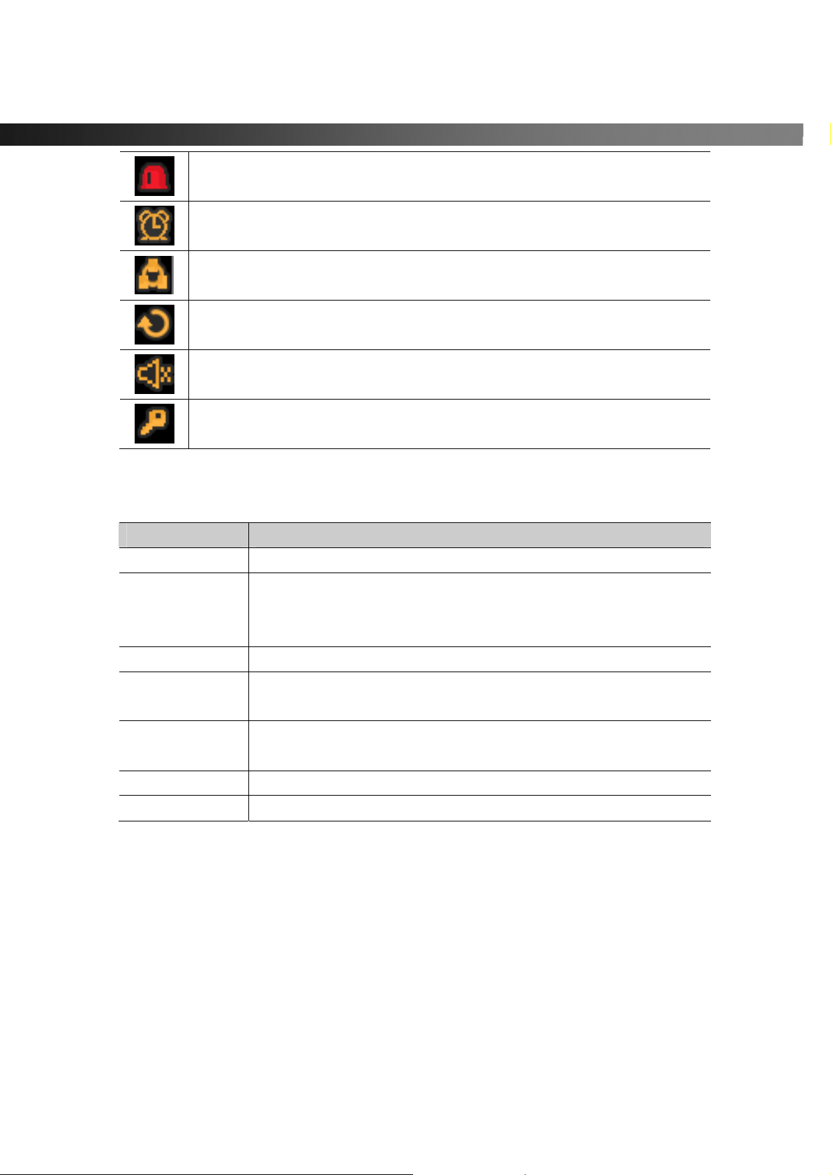
Alarm indicator. This icon changes to bright red upon alarm activation
(sensor alarm or motion alarm) for any video channel.
Indicates activated alarm output.
Indicates network client is connected to the DVR.
Indicates sequencing mode is enabled.
Indicates Audio status is enabled/disabled.
Indicates the vSync DVR is locked
Table 4.1.2. Button Functions in Live Window
Button Description
SETUP
SEQ
PLAY/P AUSE
Directional
Buttons
SEL
ESC
REC
Launches SETUP menu.
Enables/disables automatic sequential switching in full or quad
modes.
Quad mode also follows these settings.
Launches the SEARCH window.
Select a channel by using the directional keys. Selected channels
show the channel ID in yellow.
When a channel is selected, press SEL button to expand the
channel to full screen.
No action, backs out of last menu.
St arts manual recording for all channels.
Rev A. December 2007
Specifications and content are subject to change without notice.
38
Page 39
vSync924 & 1624i User Guide © vSync DVR December 2007
4-2. Search Window
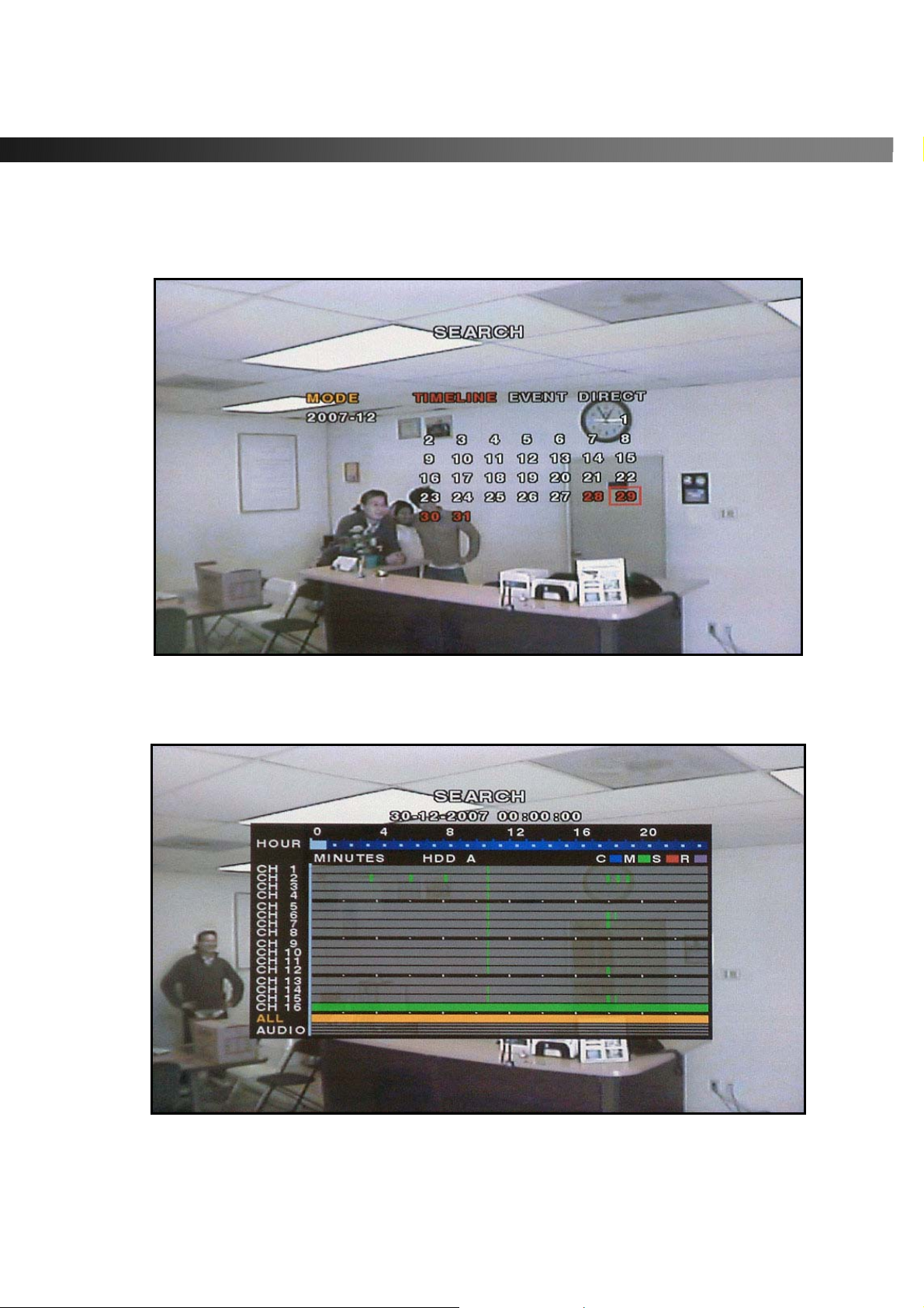
Press PLAY/PAUSE button to launch the search menu. The screenshot shown in Figure 4.2.will appear.
Select “
TIMELINE
”, “
EVENT
”, or “
DIRECT
” to initiate a search for recorded video.
Figure 4.2. Search Mode Screen
4-2-1. TIMELINE Window
Figure 4.2.1. Timeline Search Mode Screen
Rev A. December 2007
Specifications and content are subject to change without notice.
39
Page 40
vSync924 & 1624i User Guide © vSync DVR December 2007
1. Select the option “TIMELINE” and a calendar will appear (Figure 4.2.1).
2. Select the date of the video by using the LEFT, RIGHT, UP, and D OWN buttons to navig ate through
the days.
3. Press the SEL button to move to the timeline search window.
4. Use LEFT/F. REW or RIGHT/F. ADV buttons to select a starting time period on the 24 hour
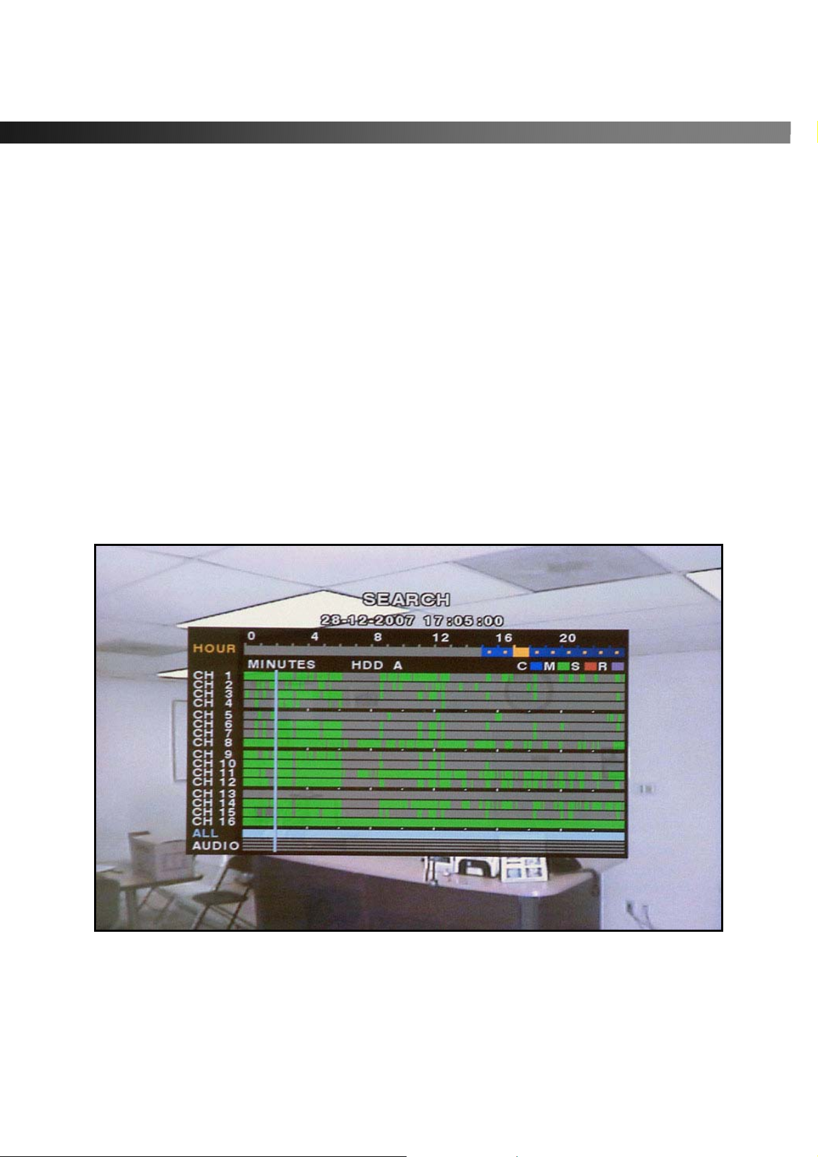
timetable.
NOTE: The modes used during recording ar e indi c at ed bel o w.
C: Continuous
M: Motion
S: Sensor
R: Emergency Record
5. Once you have selected the date, press the SEL button to move to the hourly timetable.
6. Select a specific channel or All Channels by using the UP and DOWN arrow buttons.
7. Once you have selected the channel(s), use the LEFT/F. REW or RIGHT /F. ADV buttons to move
the timeline select bar (purple) to the point you wish to start playing the video clip.
8. Press the SEL button to playback the recorded video.
Figure 4.2.1-1. Motion Recording Search Mode Screen
Rev A. December 2007
Specifications and content are subject to change without notice.
40
Page 41
vSync924 & 1624i User Guide © vSync DVR December 2007
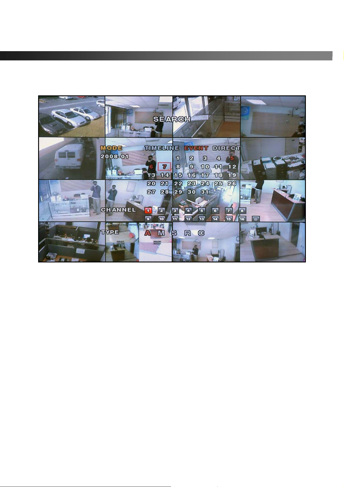
4-2-2. EVENT Window
Figure 4.2.2. Event Search Mode Screen
1. Select the option “EVENT” and a calendar will appear (Figure 4.2.2).
2. Select the date of the video by using the LEFT, RIGHT, UP, and DOWN buttons to navigate through
the days.
3. Press the SEL button to move to CHANNEL selection.
4. Use the LEFT, RIGHT, UP, and DOWN buttons to select a specific channel or All Channels.
5. Press the SEL button to move to TYPE selection.
6. Use the LEFT, RIGHT, UP, and DOWN buttons to select A ll, Motion Only, Sensor Only, Emergency
Record Only , or Continuous Record Only.
7. Press the SEL button to see the event list.
8. Use the UP and DOWN buttons to scroll through the list and use the R IGHT and LEFT buttons to
move between pages.
9. Press the SEL button to playback the recorded video.
Rev A. December 2007
Specifications and content are subject to change without notice.
41
Page 42
vSync924 & 1624i User Guide © vSync DVR December 2007
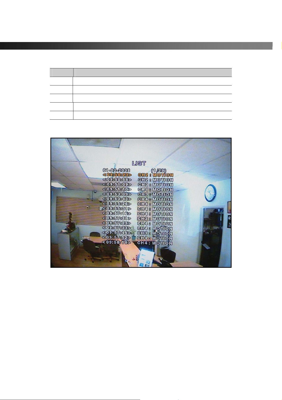
Table 4.2.2-1 ICONS in Event Search Mode Screen
Icon Description
A
M
S
R
C
Select All recording
Select Motion alarm recording only
Select Sensor alarm recording only
Select Manual recording only
Select Continuous recording only
Figure 4.2.2-1 Event Search List
Rev A. December 2007
Specifications and content are subject to change without notice.
42
Page 43
vSync924 & 1624i User Guide © vSync DVR December 2007
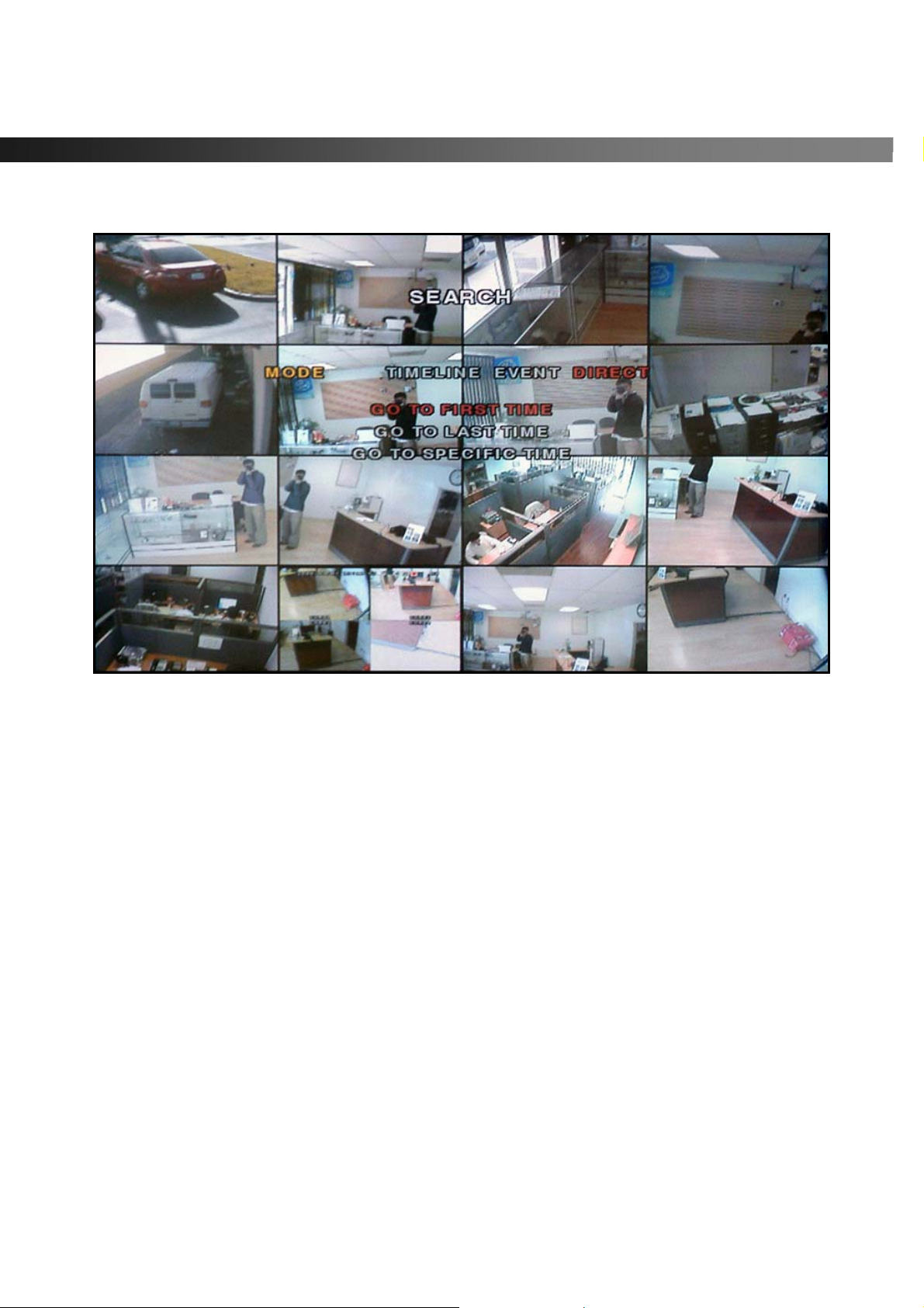
4-2-3 DIRECT Window
Figure 4.2.3. Direct Searc h List
Go To First Time
You can access the oldest recorded data on the DVR hard drive by selecting GO TO FIRST TIME under the
DIRECT optio n.
Go To Last Time
You can access the latest recorded data on the DVR hard drive by selecting GO TO LAST TIME under the
DIRECT optio n.
Go To Specific Time
You can search for video data from a specific instanc e by s ettin g the date and time i n the GO TO SPECIFIC
TIME search window.
Use the LEFT or RIGHT arrow buttons to move through the date and time values in this menu.
Use the UP and DOWN arrow buttons to change the date and time values.
Press SEL when the appropriate date and time is entered to playback the recorded video file.
Rev A. December 2007
Specifications and content are subject to change without notice.
43
Page 44
vSync924 & 1624i User Guide © vSync DVR December 2007
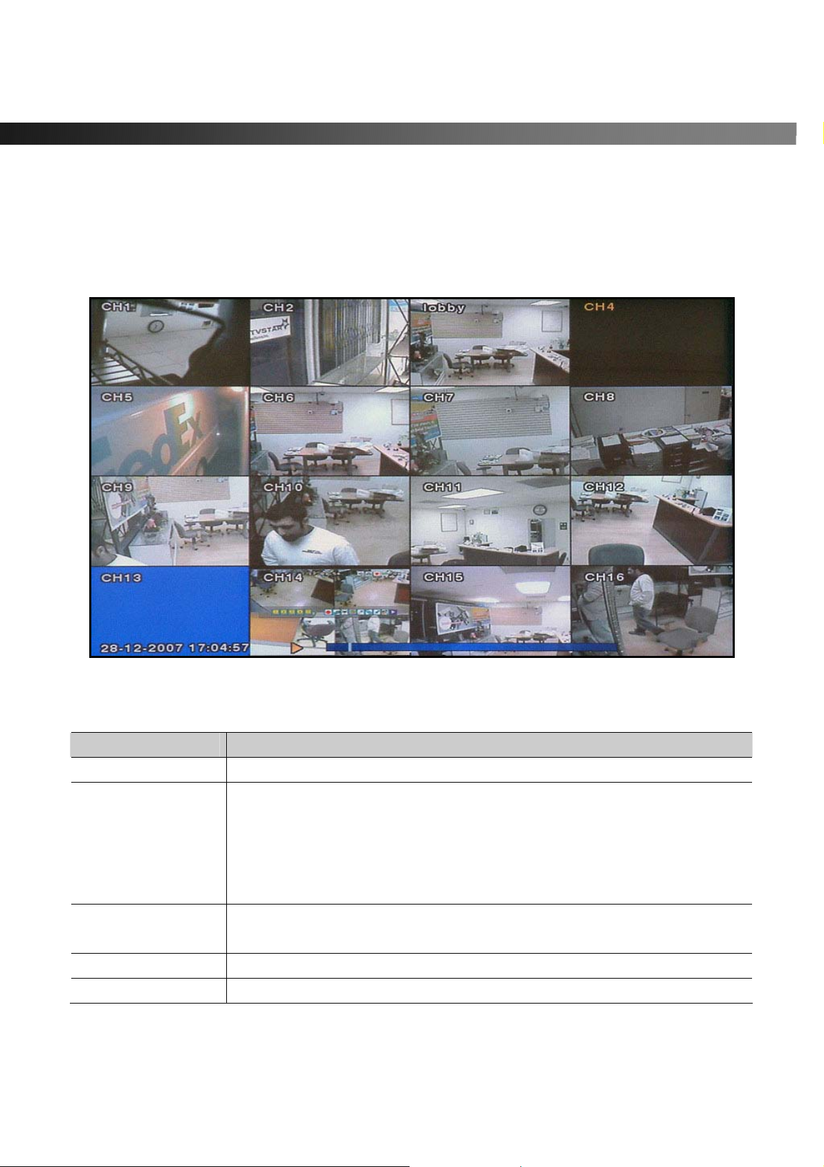
4-3. Play Mode
During recorded event playback, vSync DVR switches from the SEARCH screen to PLA Y mode.
To return to the SEARCH LIST press the ESC button.
Figure 4.3.1. Play Mode Screen
Table 4.3.1. Button Functions in Play Mode
Button Description
ESC
REW
F/REW
PLAY/PAUSE
F/ADV
Rev A. December 2007
Specifications and content are subject to change without notice.
Returns to the previous menu screen or exits from the setup menu.
Rewinds. Pressing repeatedly adjusts playback speed.
Reverse playback speeds are indicated as -1x, -2x, -4x and -8 x for normal,
twice, 4 and 8 times normal speed.
The current speed is shown on the bottom right hand corner of the screen.
Caution: Max 4x when playing 16 channels at once.
Jumps/Step Backward – The playback position moves 60 seconds
backward.
Plays or pauses recorded video.
Jumps/Step Forward – The playback position moves 60 seconds forward.
44
Page 45
vSync924 & 1624i User Guide © vSync DVR December 2007
Fast forwards. Pressing repeatedly adjusts playback speed.
FF
Directional Buttons
SEL
CAP/USB
Fast forward playback speeds are indicated as +1x, +2x, +4x and +8x for
normal, twice, 4 and 8 times normal speed.
The current speed is shown on the bottom right hand corner of the screen.
Caution: Max 4x when playing 16 channels at once.
Used to move between the channels.
Change to full, quad, or 9/16 split display by using the SEL button.
Press to launch the archive feature.
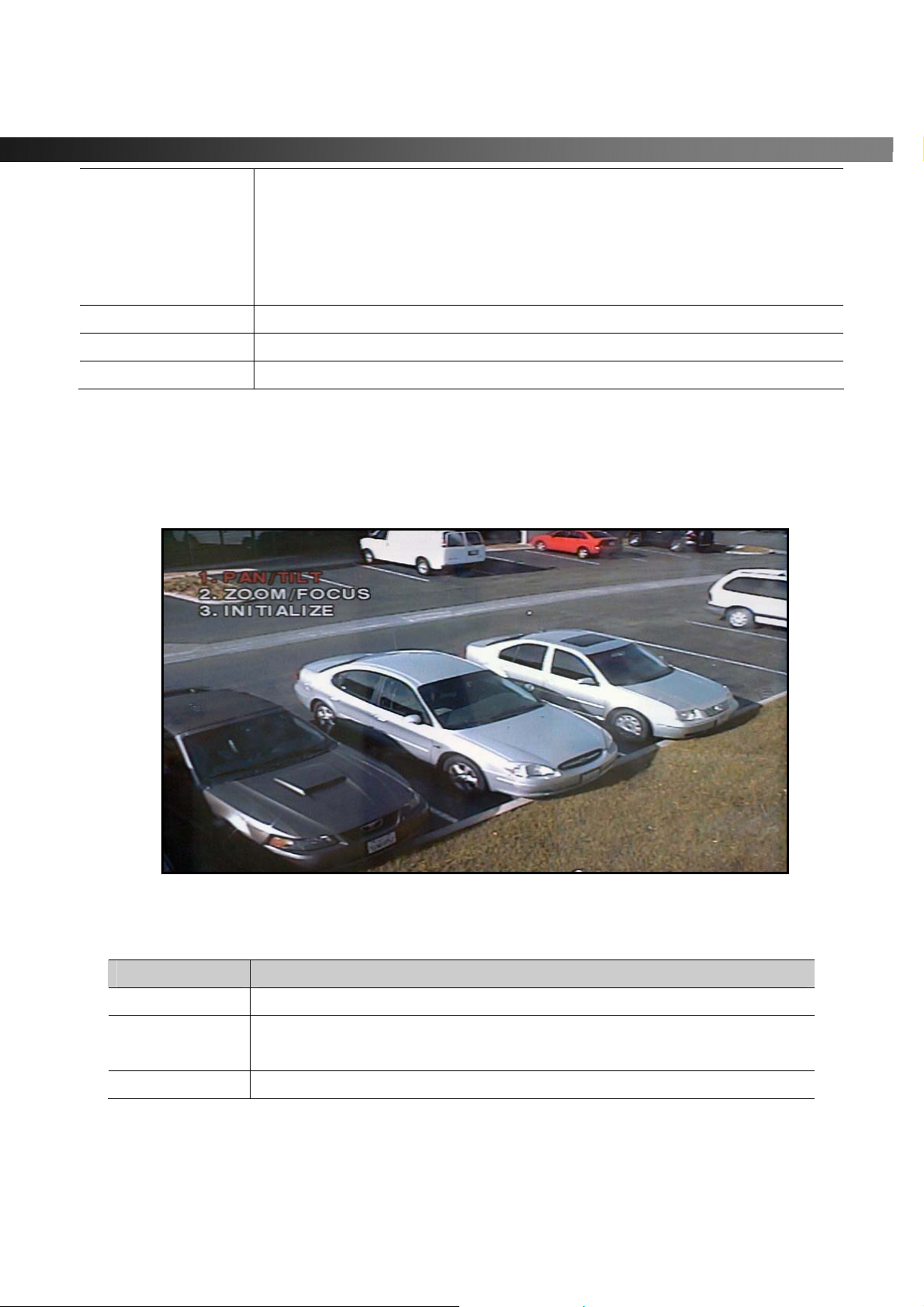
4-4. PTZ Control
NOTE: Requires previous configuration of PTZ devices in SETUP Mode. Press the PTZ button to initiate
device control features for a selected channel. See Figure 4.4.1. Select a menu item for the respective
control features.
Figure 4.4.1. PTZ Control Screen.
Table 4.4.1 PTZ Control Menus
Item Description
PAN/TILT
ZOOM/FOCUS
INITIALIZE
Rev A. December 2007
Specifications and content are subject to change without notice.
Select menu and use the directional keys for Pan and Tilt.
Select menu and use the UP/DOWN keys for Zoom control.
Use the LEFT/RIGHT keys to control focus.
Initializes PTZ function on selected cameras.
45
Page 46
vSync924 & 1624i User Guide © vSync DVR December 2007
5. Archiving Video via USB, or CD-RW
Archives a still image or video clip onto a USB storage device or CD. Data must be captured before
archiving.
5-1. Capturing Images or Video Clip
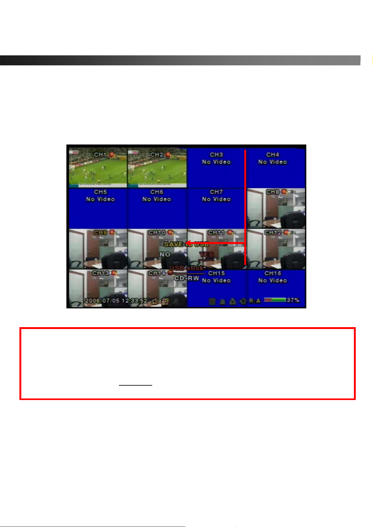
Capture still images in live mode or while playing back recorded video. In Live mode, pressing the
CAP/USB button twice initiates capturing a still image. See Figure 5.1.1 for an example.
Figure 5.1.1. Archive Mode Screen
The still image is stored on the ha rd disk drive and may be transferred to a USB storage device by selecting
YES, or a CD-RW disk by selecting CD-RW.
User can select backup to USB or CD-RW.
Do you want to backup? NO YES
Select media to backup USB stick
CD-RW
1. From playback mode, pressing the CAP/USB button launches the archiving menu.
2. vSync DVR offers two choices, store still image or video. Selecting still images or video captures the
respective type of file to the hard disk.
3. Insert a USB storage device or CD. Select the corresponding type of storage device, USB or CD-RW.
vSync DVR converts the file to a AVI file type and writes to the selected device.
Rev A. December 2007
Specifications and content are subject to change without notice.
46
Page 47
vSync924 & 1624i User Guide © vSync DVR December 2007
5-2. Transferring Still Images or Video Clips onto USB or CD-RW
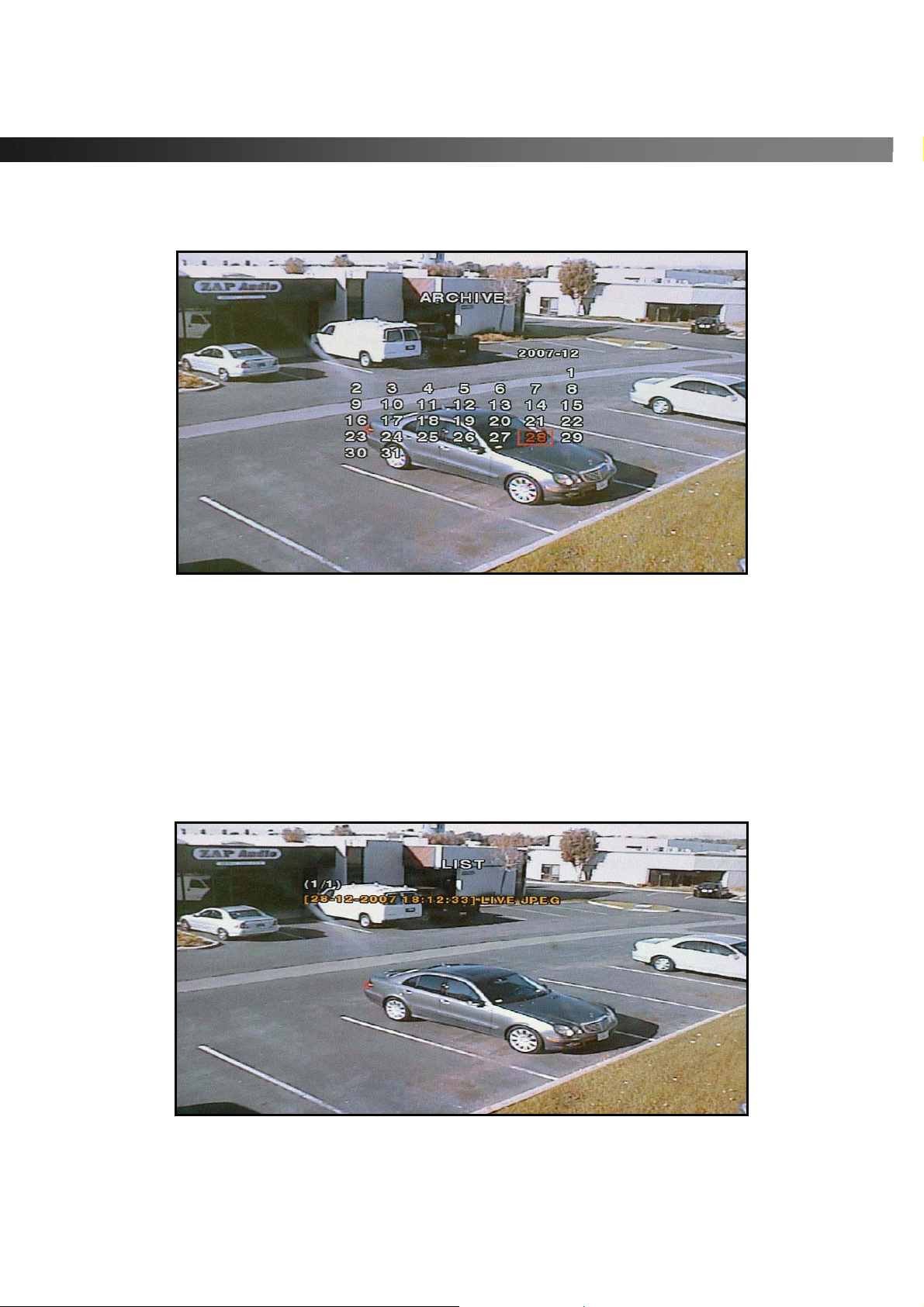
From live mode, press the ARCHIVE button. This launches the ARCHIVE screen, which prompts with a
calendar for date selection.
Figure 5.2.1. Archive Menu Screen
1. Press the SEL button to retrieve a list of archived images or video clips for the selected date.
2. Select a file from the archive list by using the UP or DOWN buttons and the RIGHT or LEFT buttons
to move between pages.
3. Press the CAP/USB button to transfer to a USB storage device or CD -RW. vSync DVR checks for free
space and will not save a file if there is insufficient free space on the storage media.
4. Video files are automatically converted to the AVI file format allowing easy playback from Windows Media
Player, or other Media Players supporting MPEG4/AVI file formats.
Figure 5.2.2. List of Archived Files
Rev A. December 2007
Specifications and content are subject to change without notice.
47
Page 48

vSync924 & 1624i User Guide © vSync DVR December 2007
vSync DVR converts USB archived video to the AVI file format for easy viewing with Windows Media Player
10 or higher. If the archived video from vSync DVR c an not be played with standard video software, it is
recommend that you install the FFDSHOW codec included on the installation CD on your Microsoft
Windows based PC to properly review archived video files saved on the USB storage device or CD.
5.2.1. How to install Codec
1. Insert the vSync
2. Open Codec folder.
3. Double-click the file ffdshow-rev1322_xxxxx.exe to install codec program.
4. Follow the setup wizard and install using the initial settings for codec, filters, etc.
Note: In case of any technical difficulties with replaying archived video clip, please contact the vSync DVR
distributor or download GOM Player from: www.gomplayer.com
GOM Player is a multimedia player that is free to download with a relatively small file at 4.13MB, free of
spyware and malware.
installation CD provided with vSync DVR into the CD drive of your computer.
.
Rev A. December 2007
Specifications and content are subject to change without notice.
48
Page 49
vSync924 & 1624i User Guide © vSync DVR December 2007
5.2.2. Time Stamp Display
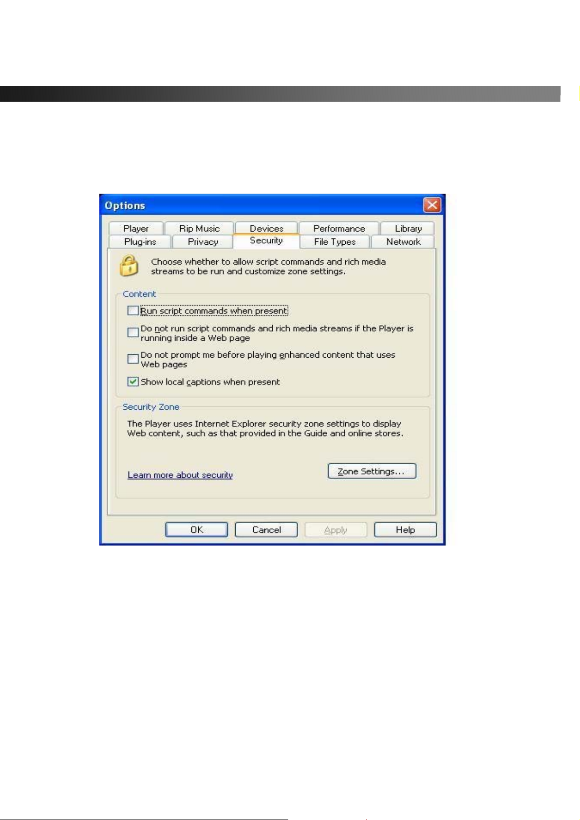
Due to the enhanced security of Window s Media Player 10 running on Windows XP, some further setup is
required.
In Windows Media Player, go to Tools->Options->Security, then check “Show local captions when present”
as shown below.
Figure 6.2.3. Setup Screen for Window Media Player 10
Caution!
Always backup the contents of your USB storage device before archiving data from vSync DVRs.
- Improper handling of a USB storage device may cause it to become unstable.
Unplugging the USB storage device during a data transfer can cause system errors on the USB storage
device’s file system.
Before archiving to a USB storage device, always ensure that there is enough free storage space remaining
in the device.
Rev A. December 2007
Specifications and content are subject to change without notice.
49
Page 50

vSync924 & 1624i User Guide © vSync DVR December 2007
6. Firmware Upgrade
6-1. Preparing USB storage device with Upgraded Firmware
1. Before upgrading the system with your USB storage device, create the following directory
“E:\upgrade” (E:\ is just an example, your drive letter may be different).
2. Copy the firmware file to the \upgrade folder.
3. Double-check the name of the firmware file. The filename should be “app9.bin” for the vSync924i (9
Channel DVR) and “app16.bin” for the vSync1624i (16 channel DVR).
6-2. Steps to Complete Upgrade
1. Press the Setup button and enter the password. Default password is 1111
2. Select Security menu from the Setup Screen.
3. Select Admin Password followed by “12341234” and the SEL button.
4. The DVR will reboot in Test Mode.
5. Plug in the USB storage device containing the upgrade firmware.
6. Select the USB UPGRADE option to start the upgrade.
7. After the upgrade is finished, select the BOOT APPLICATION option and the DVR will restart to
launch the new, upgraded firmware.
6-3. V erifying Software Installation.
1. Press Setup and log on.
2. Select System and press SEL.
3. Select Description and press SEL.
4. Check the version displayed.
The version number should match the new firmware version you have installed.
Rev A. December 2007
Specifications and content are subject to change without notice.
50
Page 51
vSync924 & 1624i User Guide © vSync DVR December 2007
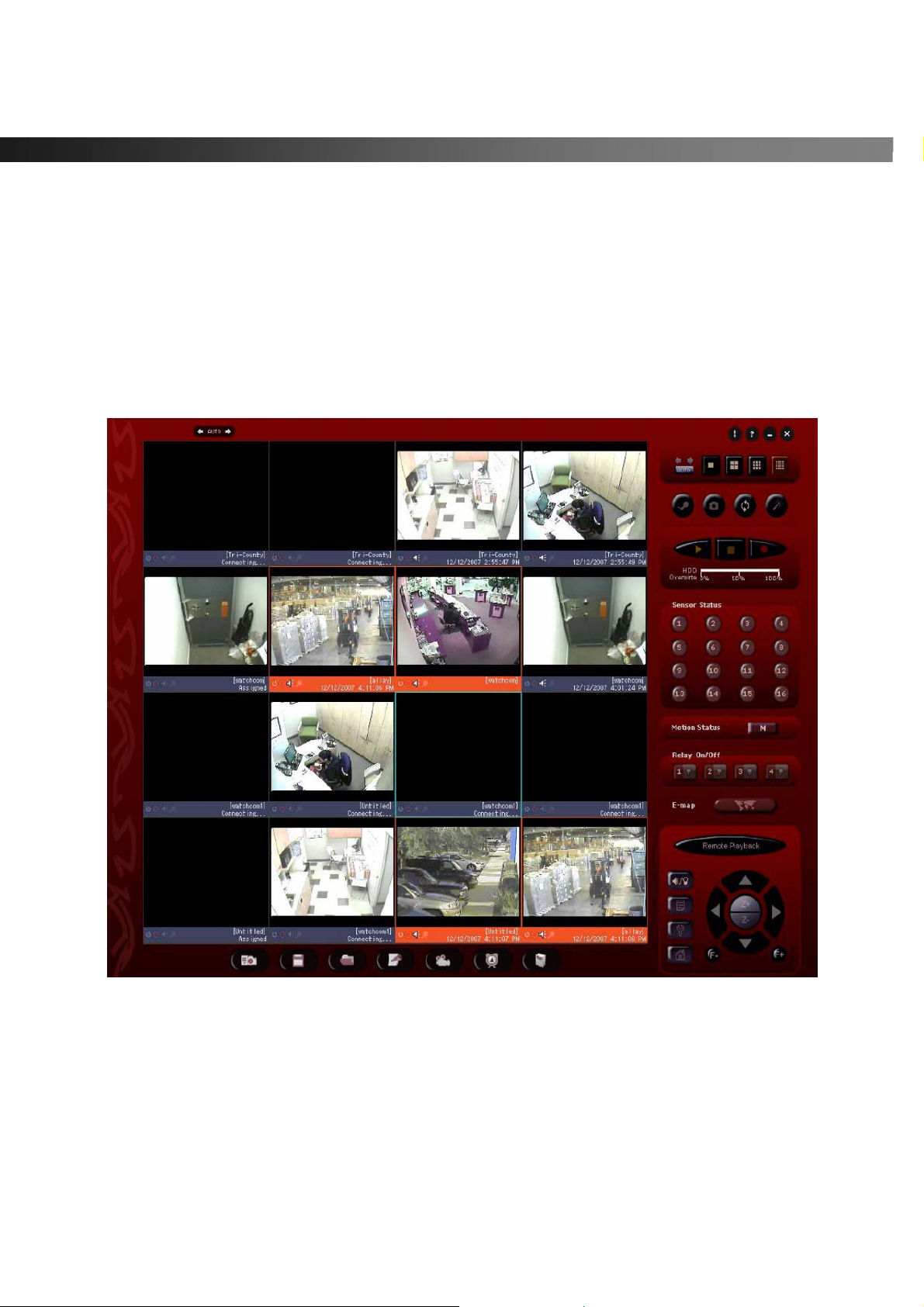
7. Network Client - Remote Monitoring and Playback
1. Install the vSync network client software to your PC.
2. Follow the appropriate instructions in the instructions detailed in section 3-7.
3. Connect the vSync DVR to the Network via the Ethernet Port on the rear of the DVR
4. The vSync Network Client Software features are explained in a separate manual.
When recording is in progress, vSync streams/transmits video identical to the quality settings applied in the
record setup menu.
Figure 7.1. vSync Remote Client for Live Monitoring and Remote Search/Playback
For Networks with Limited Upload Bandwidth
Turning “BANDWIDTH SAVING ON” forces the vSync DVR to send only i-frames, saving network
bandwidth. You can find this feature in the Network setup screen.
Rev A. December 2007
Specifications and content are subject to change without notice.
51
Page 52

vSync924 & 1624i User Guide © vSync DVR December 2007
8. Remote Setup Using Embedded Web-Server of vSync924i & 1624i
******** Requires Configuring Network Settings in Section 3-7 *************
vSync client software provides a remote web interface to access most setup parameters. Please note that
Schedule and Motion Zone setup parameters are not supported
To connect to the admin page over the web you can either click on the “Magic Wand/Admin” button
in the vSync client program or type http://ip-address:http-port/admin.htm
(ex: http://xxx.xxx.xxx.xxx/admin.htm
(Only Microsoft Internet Explorer is supported, we do not support other third-party browsers, i.e. FireFox.)
Before loading the admin page, the browser will prompt for the User ID and Password.
The default values are “root” and “dw2001,” respectively.
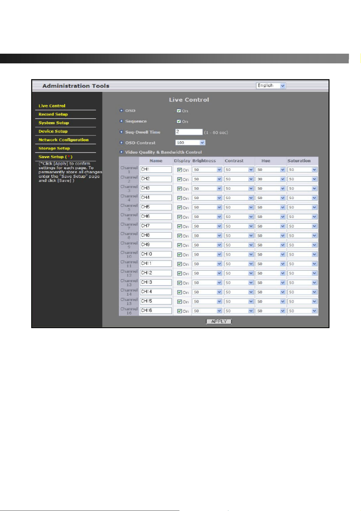
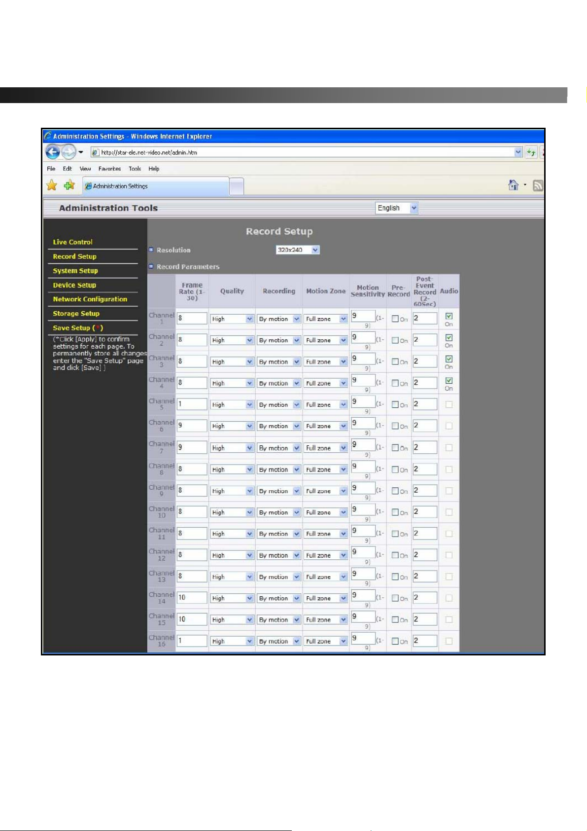
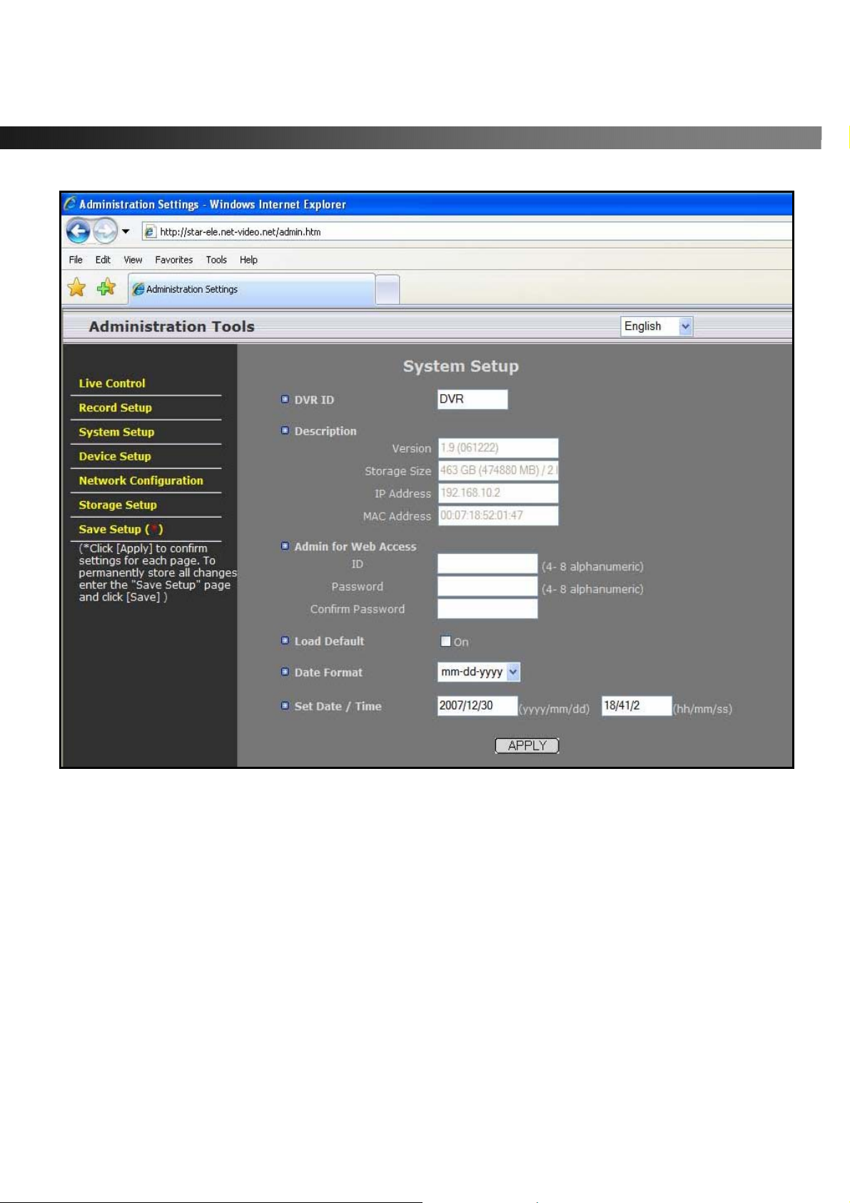
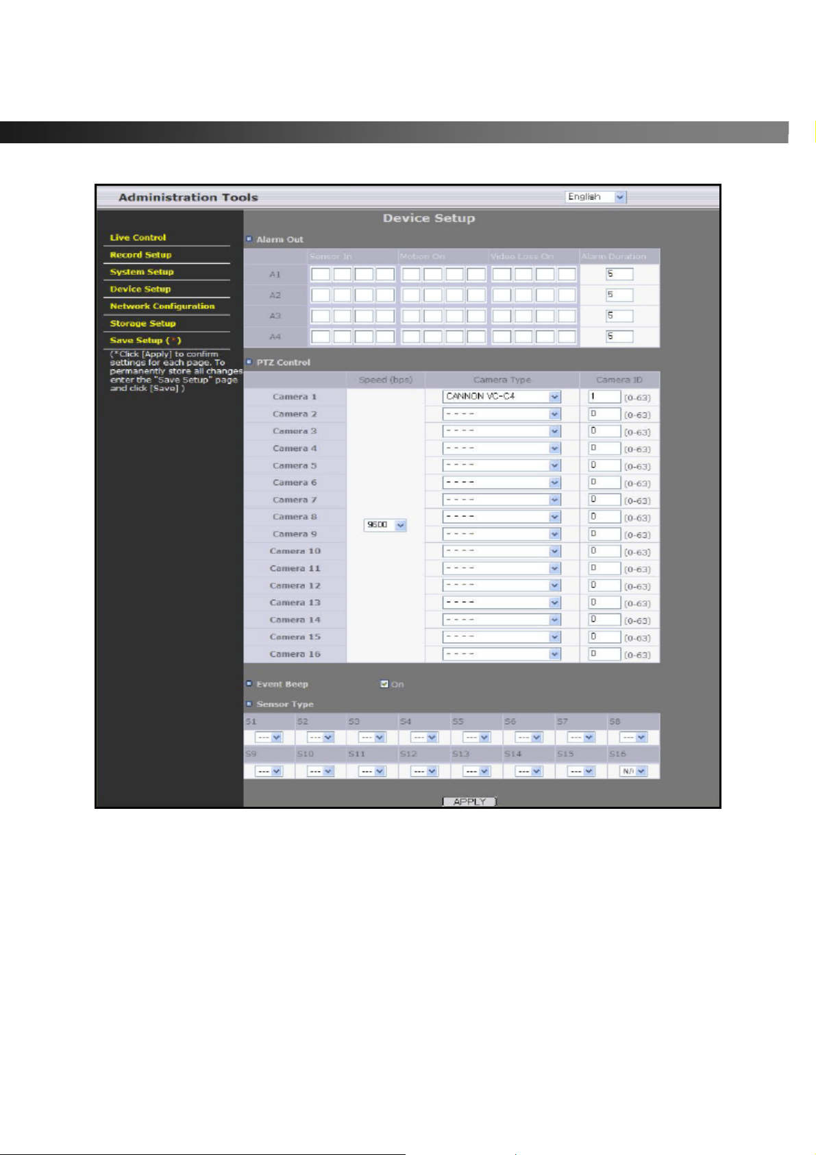
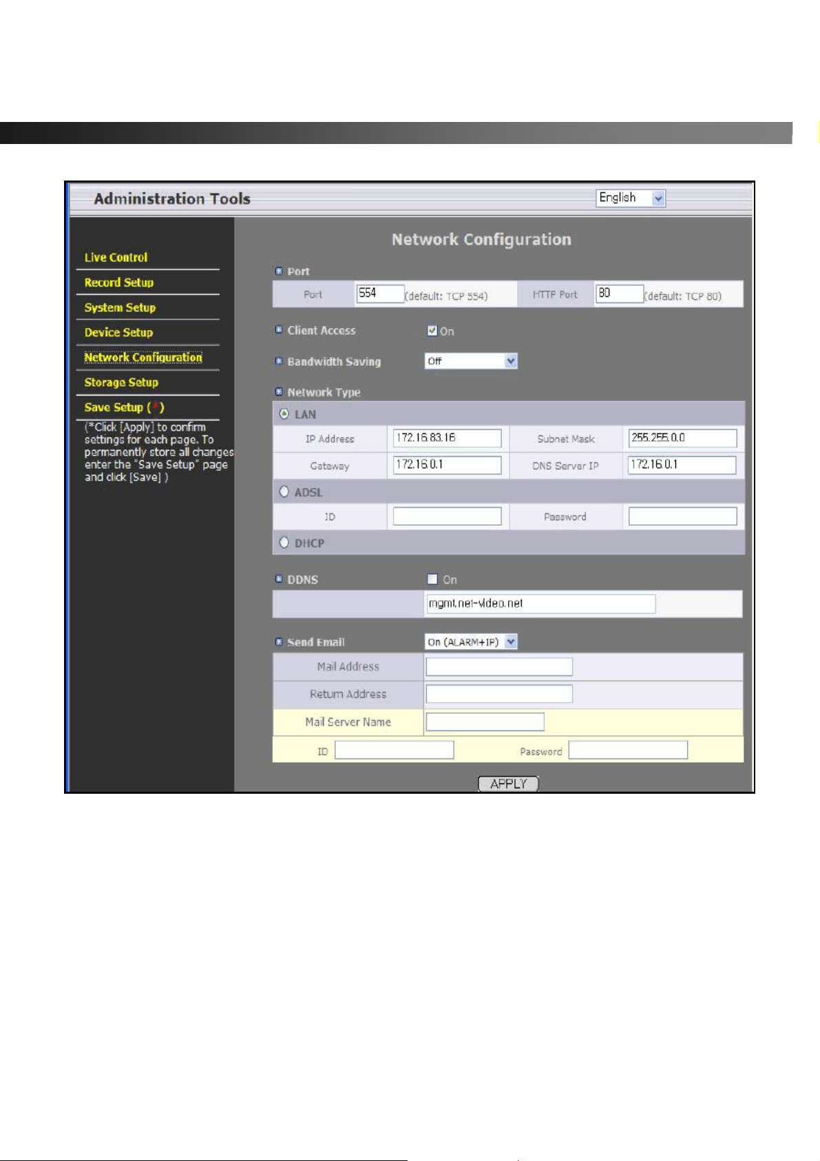
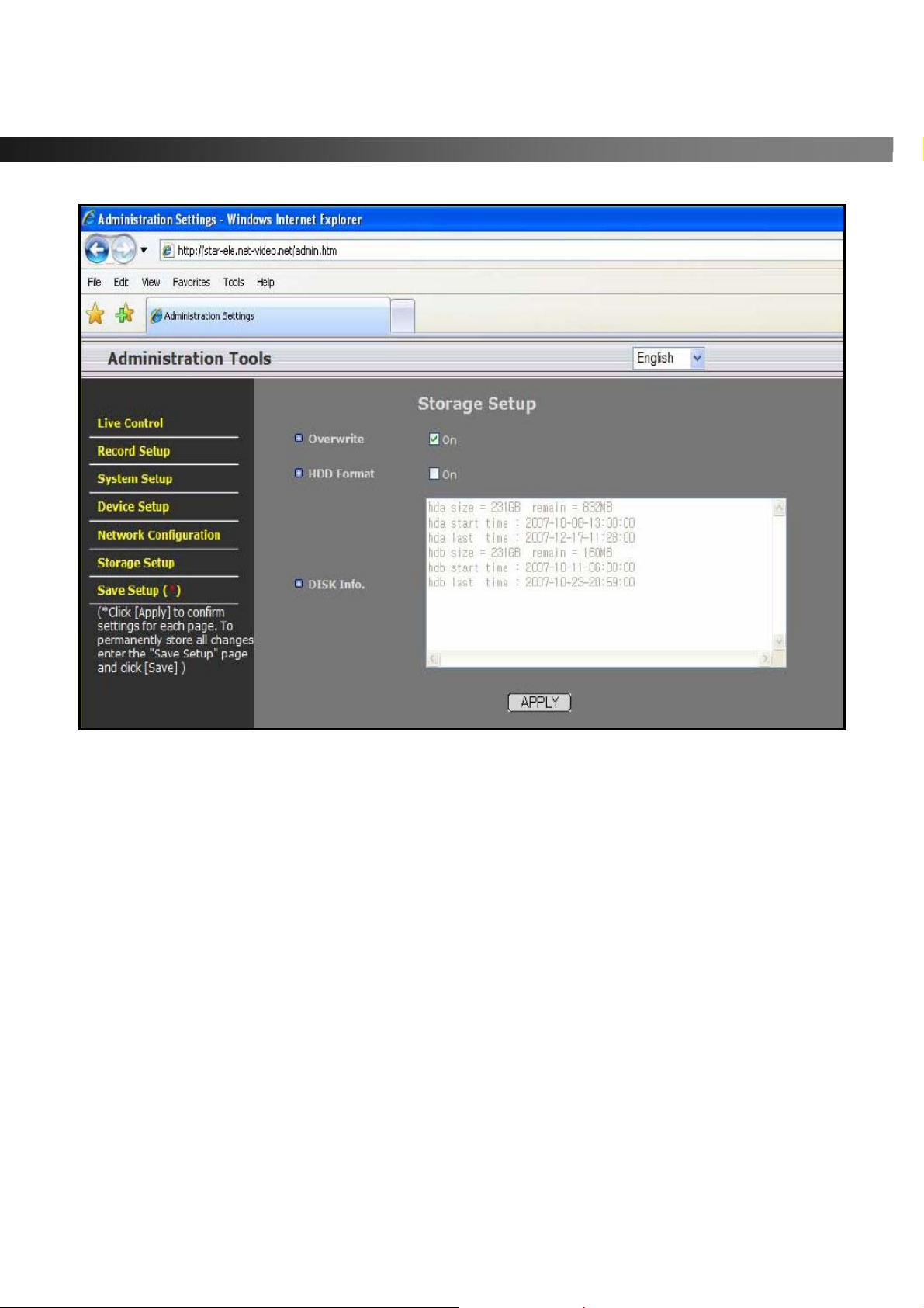
See Figures below for examples of Setup pages for each category. After setting all the parameters for each
page, make sure to press the APPLY button at the bottom of the page to temporarily store these
settings.
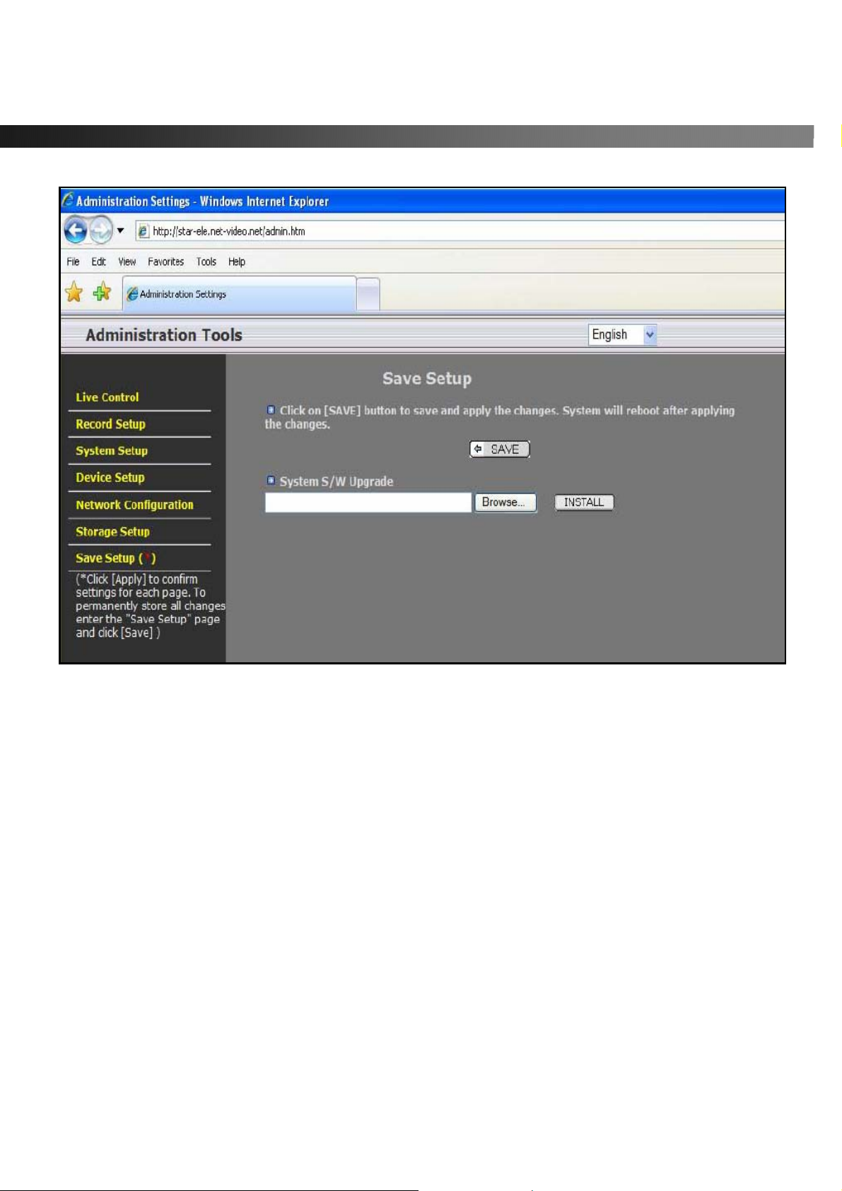
After inputting all setup values, go to the “Save Setup” menu and press the SAVE button. The system will
reboot to allow the new parameters to take place.
)
via the web interface.
in Microsoft Internet Explorer.
To protect your DVR from unauthorized use, we strongly recommend changing the User ID and
Password.
Rev A. December 2007
Specifications and content are subject to change without notice.
52
Page 53
vSync924 & 1624i User Guide © vSync DVR December 2007
Figure 8.1. Live Control Setup Page
After finishin g the set up on the page click on “
APPLY
Rev A. December 2007
Specifications and content are subject to change without notice.
” for temporal storage of the parameters.
53
Page 54
vSync924 & 1624i User Guide © vSync DVR December 2007
Figure 8.2. Record Setup Page
Rev A. December 2007
Specifications and content are subject to change without notice.
54
Page 55
vSync924 & 1624i User Guide © vSync DVR December 2007
Figure 8.3. System Setup Page
Rev A. December 2007
Specifications and content are subject to change without notice.
55
Page 56
vSync924 & 1624i User Guide © vSync DVR December 2007
Figure 8.4. Device Setup Page
Rev A. December 2007
Specifications and content are subject to change without notice.
56
Page 57
vSync924 & 1624i User Guide © vSync DVR December 2007
Figure 8.5. Network Configuration Page
Rev A. December 2007
Specifications and content are subject to change without notice.
57
Page 58
vSync924 & 1624i User Guide © vSync DVR December 2007
Figure 8.6. Storage Setup Page
Rev A. December 2007
Specifications and content are subject to change without notice.
58
Page 59
vSync924 & 1624i User Guide © vSync DVR December 2007
Figure 8.7. Save Setup Page
Rev A. December 2007
Specifications and content are subject to change without notice.
59
 Loading...