


ASSEMBLY MANUAL
ver.1.11b
Vstone

0. INTRODUCTION
11
READ FIRST
Thank you for purchasing our bipedal robot assembly kit “Robovie-X.” The Manual
describes assembly of the robot and handling of its accessories. Read it thoroughly to
assemble the Product with care.
- The Product is an assembly kit. It may not be able to exhibit its intended performance
depending on how you assemble it. If you cannot assemble it properly, utilize our
support services. For details, see Page 71 “9. INQUIRIES ABOUT TROUBLES,
MISSING PARTS, DAMAGE, ETC.”
- Assembly and operation of the Product assumes use of a personal computer
(hereinafter, to be referred to as the PC). The Manual and other accompanying manuals
have been prepared, assuming that you are familiar with basic operation of the PC.
Note that we cannot answer any questi ons or inquiries about operation of the PC or
Windows.
*The specifications are subject to change without prior notice due to
improvement or enhanced performance.

PRECAUTIONS PRIOR TO ASSEMBLY
22
• Note that the Product is an assembly kit and does not always assure robot operations after its assembly.
• When you use, assembly or store the Product and its parts, make sure that there are not infants around
you. The Product comes with small parts. Care should be taken so that they will not swallow them by
mistake.
•The Product is not a toy. When it is operated by a child, his/her parent must be present to watch.
•Do not wet the Product or its part, or use/store them at high humidity or in an environment where due
condensation may occur.
• Use the tools with utmost care paid to safety.
•Do not disassemble or remodel servo motors and PC boards because they are precision electronic parts.
Neglect of this may cause a trouble or a resultant electric shock or fire.
• Care should be taken not to allow conductive foreign substances into contact with the PC boards.
- As the terminals of the PC boards are exposed, they can be easily short-circuited by conductive foreign
substances (metals, water, etc.). Short-circuit could result in a PC board failure or ignition of the battery or
wiring.
• When you adjust or operate the Product after its assembly, it may move in an unexpected way in the
nature of the assembly it. It may tumble or drop to injure you or get damaged. Secure sufficient work
space and operate. Handle the Product with utmost care because it may catch your finger while operating.
•Connect the connectors securely, paying attention to their polarity. Neglect of this could cause a trouble
or fire.
• Do not allow the cables to be caught when assembling. Catching of the cable could cause snapping or
short-circuit.
• When disconnecting a cable, hold its plug and connector.
If it is disconnected by holding its cord, an electric shock or fire may be caused by snapping or short-
circuit.
•For handling of the battery and battery charger, be sure to observe the instructions described in the
Instruction Manual, Robovie-X Assembly Manual and Robovie-X Software Reference.

1. CONTENTS
33
0. INTRODUCTION
1. CONTENTS
2. UTENSILS REQUIRED
3. ACCESSORIES
3-1. Major Parts
3-2. List of Parts Used
4. CHARGER AND BATTERY
4-1. Precautions for Handling
4-2. Charging Method
5. PRELIMINARY KNOWLEDGE PRIOR TO ASSEMBLY
5-1. Servo Motor Origin
5-2. Screws and Precautions for Screwing
6. SETTING OF SERVO MOTOR ORIGIN
7. ASSEMBLY
7-1. Assembling the Right Arm
7-2. Assembling the Left Arm
7-3. Assembling the Right Leg
1
3
4
5
5
6
11
11
12
13
13
14
15
18
21
23
25
7-4. Assembling the Left Leg
7-5. Assembling the Body
7-6. Mounting the Arms and Legs to the Body
7-7. Checking the Movable Ranges
7-8. Wiring and Mounting the Head Armor
7-9. Mounting the Body Armor
7-10. Pasting the Sole Tape
8. INSTALLATION OF BATTERY
9. INQUIRIES ABOUT TROUBLES, MISSING PARTS, DAMAGE, ETC.
APPENDIX: EXTENSION OF FUNCTIONS
31
37
44
54
58
64
69
70
71
72

2. UTENSILS REQUIRED
44
The following utensils are required for assembly and operation of the Product.
Prepare them in advance.
•PC (Personal Computer)
CPU: Pentium 3 or later (1 GHz or more recommended)
RAM: 128 MB
OS: Windows 2000/XP/Vista
Screen size: XGA or above
Interface: USB
Should be equipped with a CD-ROM drive.
•Tools
- Cutting pliers (used in “7-5. Assembling the Body, Step 15” on Page 43)
- Scissors (used in “7-10. Pasting the Sole Tape” on Page 69)
- Screwdrivers
No. 1 Phillips screwdriver (handle diameter = 1 cm or more)
No. 0 and No. 1 Phillips precision screwdrivers
#1
#0
Precision Screwdrivers
Other Useful Utensils
Regular screwdrivers, tweezers, towel, Scotch
tape, screw container

3. ACCESSORIES
55
3-1. Major Parts
The following outlines the specifications of the main parts included in the Product.
Servo motor VS-S092J
Dimensions : 38 x 19 x 38.5mm
Torque:9.2kg cm
Speed:0.11S/60°
Weight:42g
Max. operating range:180°
Max. voltage: 4 V to 9 V (7.4 V measured)
Control method:PWM
Small CPU board for the robot VS-RC003HV
Dimensions:52x48(44)x13mm
Weight:21g
Servo motor output:30ch
Audio output:2W
Corresponding voltage 5 V to 16 V
Interface with PC:USB (HID)
Corresponding controller: Game pad, ProBo
Extension port:IXBUS x1
Battery
Nickel metal hydride battery
1,400 mAh, 5 cells (6.0 V)
(Option)
Gyro sensor/acceleration sensor extension board
VS-IX001
Dimensions: 25 x 30mm
Mounted sensors: 2-axis gyro sensor
3-axis acceleration sensor

3-2. List of Parts Used
66
Check if all the component parts are included.
VS-X Bracket A
( a 2101 )
* Note that the brackets A and B are very similar to each other.
R
VS-X Bracket C
( a 2301R- a2301L )
VS-X Bracket B
( a 3302 )
L
Standard Sole Set A
( a 2501 )
(a 2202)
VS-X Servo Holder A
( a 2202-a 2201 )
(a 2201)
Standard Hand Bracket A
( a 3301R- a 3301L )
VS-X Servo Holder B
( a 2502 )
LR
VS-X Servo Holder C
( a 2302 )

( a 1101 ) ( a 1102 )
77
( a 1103 )
VS-X Standard Body Set
( a 1104 )
( a 1105 )( a 1106 )( a 1107 )
One Each
(a 1103)x 2
Initial Position Adjusting Part
( a 4102 )

One Each
88
Rear of HeadFront of Head
Rear Head ArmorFront Head Armor
One Each
Front Body Armor Rear Body Armor
x1
Decal

Major Parts
99
CPU Board
VS-RC003HV
Battery Charger
Long Cable 40cm
USB Cable Power Cable
Short Cable 15cm
Servo Motor VS-S092J
Game Pad
Conversion Connector
(Optional Part)
This part allows the robot to automatically balance itself to prevent tumbling.
Speaker
Servo Horn
LED Board
VS-LED1
Gyro Sensor/Acceleration Sensor Extension Board
VS-IX001
Sole Tape

Screws
1010
M2-
3
Screw A
M2-3 Flat Pan Head
M3-
5
Screw C
M3-5 Flat Pan Head Cap
M2-
Screw F
M2-4 Flat Head Tapping
M3-
Screw H
M3-8 Flat Head Tapping
T T
4
T
8
M2-
5
Screw E
M2-5 Flat Head Tapping
Tapping screw
T
Bind tapping screw
B
Spacer
S
4
B
M2-
Screw G
M2-4 Bind Tapping
3
S
M2-
Spacer A
M2-3 (Hexagonal Spacer)
Friction Rubber
M2-
5
Spacer B
M2-5 (Hexagonal Spacer)
Bush DURACON Washer
Urea Resin
Urea Resin Nut
Binding Band
: Denotes the required quantity.
Parenthesized is the number of spare parts.
The Product includes the total of both.
*Four of them are for the optional part.
Binding Band Washer

4. CHARGER AND BATTERY
1111
4-1. Precautions for Handling
Mishandling of the charger and battery may cause a liquid leak, ignition, trouble or injury.
Prior to using them, read the following precautions carefully.
- Store them beyond child’s reach.
- Check the polarity of the battery to connect it.
- Never short-circuit the battery.
(If the battery is stored together with a metal or a conductive substance, it may be damaged by the
conductive substance due to certain disturbance, resulting in short-circuit. When carrying them together,
put the battery in a separate case.)
- Do not wet or put the battery in water or sea water.
- Do not use or store the battery in a high-temperature, high-humidity place.
- Do not leave the battery for a long time, connected to the robot.
After using, be sure to turn off the switch of the robot.
- If the battery is not used, remove it from the robot and store it in a place with normal temperature (0 to
30ºC) and low humidity.
- Charge the battery at its temperature of 0 to 40ºC. It is dangerous if the temperature exceeds 40ºC. Cool
the battery with a cooling device.
- If you notice abnormal heat generation, foul smell or smoke while chargi ng, stop cha rging
immediately.
- If you notice abnormal heat generation, foul smell or sm oke while using the battery, turn off the
switch immediately and remove the battery from the robot.
- If you notice a liquid leak from the battery or its discoloration, deformation, foul smell or other
abnormality, do not use it.
- If the battery cannot be fully charged after the specified charging time, stop charging.
- After charging is completed, disconnect the battery immediately from the charger.
- Do not throw the battery into fire, heat it or deform it.
- Do not disassemble or remodel the battery.
- Do not peel off or damage the coating tube of the battery.
- Do no remodel a connector, etc.
- Use the charger only for the purpose of charging.
- Never use the charger as a DC power source.
- If the battery liquid gets into the eye, rinse it fully with clean tap water immediately and consult a medical
doctor.
- If the battery liquid adheres to the skin or clothing, rinse them fully with clean tap water immediately.
- The battery is basically accompanied by danger. As it could lead to a fire, do not leave it while it
is charged.
- Do not connect the fully charged battery to the charger.
- The nickel metal hydride battery may be out of service as a battery, once the voltage of each cell
is 1 V or less (5 V or less for this battery because it has 5 cells).
If it is charged in this condition, it may be damaged.
The battery voltage may drop to 5 V or less momentarily while it is operating, but it is no problem, just a
voltage drop due to the running current.

4-2. Charging Method
1212
充電方法
The battery is used at the time of assembly. Start charging prior to assembly.
(Charging is completed in a couple of hours.)
<Recheck>
- Use only the accompanying charger for the Robovie-X battery.
- Do not charge the battery near any combustible or inflammable substances.
- Do not leave the battery while it is being charged.
- Do not connect the fully charged battery to the charger.
- If you notice foul smell or abnormal heat generation,
unplug the power source immediately and disconnect the battery.
When this is done, be careful not to get burnt.
•Utensils required: Charger, conversion connector, battery
-1. Plug a Robovie-X exclusive conversion connector to the charger.
Features of Battery (Nickel Metal
Hydride Rechargeable Battery)
-2. Connect the AC plug of the rechargeable battery to a
plug socket and connect the battery, paying attention to
the polarity.
-3. A red lamp is lit up, starting charging.
Lamp
-4. Once the battery is fully charged, a green lamp will be lit up,
automatically switching to trickle charging*.
At this point, disconnect the battery from the charger.
-5. Once charging is completed, be sure to disconnect the battery
connector and the AC plug from the plug socket.
● Natural discharge
(self-discharge)
A battery discharge naturally as
time passes, even if it is not used. If
it is not used for a long time, it may
completely discharge, running out of
service. If not used for a long time,
store it fully charged. Measure its
voltage from time to time to ensure
that its voltage is not 5 V or less.
(Check every couple of months.)
The voltage can be measured with
included software “RobovieMaker2.”
● Memory effect
When using the robot, the battery
may run out in a short time, even if
it is fully charged. If the nickel metal
hydride battery is frequently
recharged (top-up charging) before
its recharged capacity is used up, it
may show an out-of-battery
phenomenon, even if it still has a
remaining capacity. This is called a
memory effect.
In order to prevent this effect, it is
recommended to charge the battery
after using up its capacity.
The memory effect can be
controlled by refresh charging
(charging after discharging) after
using several times. If you feel that
the battery capacity is lower, use it
up to the last (until the battery
voltage will be 5 V to 6 V).
Trickle charging*
A charging method to always run a minute electric current, separated
from the load, in order to compensate for natural discharge of the
battery.

5. PRELIMINARY KNOWLEDGE
1313
PRIOR TO ASSEMBLY
5-1. Servo Motor Origin
A servo motor has an important rule and concept
concerning its mounting. If it is mounted in a wrong way,
the robot will not move correctly. When assembling the
servo motor, read this page thoroughly.
The servo motor is controlled by the CPU and can be
programmed by the user to freely run. The servo motor
VS-S092J used for the Product has frame mounting holes
in the top and back covers, into which a frame is mounted.
Then, mount a servo horn to an output shaft (power
supplied shaft), followed by the frame there, to use it as
the robot’s joint. A movable range of the robot’s joint
depends on this mounting of the servo horn.
The servo motor has its movable range. The VS-S092J used for the
Product moves within a range of about 180º, that is from -90º to +90º.*
The central position of 0º is called the “origin.” If you look at the servo
motor, you can see a concave mark on the output shaft. This is called a
“neutral mark.” When the servo motor is at the origin, the neutral mark is
basically located almost directly above. (see the left figure).
However, each servo motor has a slight angle discrepancy. Even if the
angle of the origin is sent from the CPU board to the servo motor, it may be
slightly dislocated from the origin. Assuming that the origin position based
on a signal from the CPU board is correct, this robot uses software to adjust
an error produced in the actual servo motor. (An error adjusting method is
described later.)
In the following description, “origin” is used as the “origin set b y the
CPU board.” In addition to this, an error also results from wrong mounting
of the servo horn. There are 8 holes in the servo horn. The parts such as the
frame are assembled into them to transmit the power to the robot. A servo
horn mounting angle to the origin is important in order to set a movable
range of the joint more accurately.
As a test, push in the servo horn so that a hole in the servo horn will be located at the origin of the servo
motor (directly above). It should be slightly dislocated from the origin position. It is because the servo horn
is not properly aligned with the serration which conveys rotation of the servo motor to the servo horn.
There are intentionally 23 serration teeth on the circumference. If the number is increased or decreased
by 3 teeth, the hole position in the servo horn differs delicately. Try each hole in the servo horn one after
another until it is located at the most accurate angle to the origin (directly above). There should be a hole
which allows the servo horn to be located almost directly above. At the time of assembly, be su re
to carry out this work. If the origin is not accurately set, the robot cannot move successfully in
motions, such as getting up, which require an accurate movable range. (This assembly work almost
requires a hole in the servo horn to be located directly above. If it is required to be mounted at a different
position, however, we will instruct you to that effe ct.)
When mounting the servo horn to the output shaft, do not allow the servo motor’s output shaft to be
rotated.
*An operating angle differs depending on the type of the servo motor.

5-2. Screws and Precautions for Screwing
1414
• Types and Notation of Screws
M2 indicates that a thread diameter is 2 mm, and M3
indicates 3 mm.
A number following “-“ indicates the length (mm) of
threads.
Flat pan head and flat head indicate the shape of
screw head. Tapping screws refer to the screws
with rough thread pitches and are mainly used
for fixing the resin (servo horn, s ervo motor
cover, servo motor output sh aft). Non-tapping
screws are used for the areas where ordinary
threads have been cut (metal parts).
Note that if the tapping screws and ordinary ones are confused with each other, the parts will
be damaged.
As the tapping screws are used for fixing the resin, the tapped holes are damaged by
tightening them hard or putting them into the holes at a slant. Put the screws into the objective
material perpendicularly and stop tightening them when all the threads have entered into the tapped
holes.
Even when using ordinary screws to fix the objective material made of soft metal such as aluminum,
the tapped holes are damaged by tightening them too much.
• Screws and Screwdrivers
Be sure to use appropriate screwdrivers to turn the screws. They may be turned with a different size
of screwdriver, but the threads could be damaged.
No. 0 Phillips precision screwdriver: M2 screws (other than M2-4 bind tapping screws)
No. 1 Phillips precision screwdriver: M2-4 bind tapping screws, M3-5 screws
No. 1 Phillips screwdriver: M3-8 tapping screws
•Precautions for Using the Servo Horn to Fix the Parts
The frame of Robovie-X has been flexibly designed so that it can be changed into different forms.
For this reason, two frames may be combined together for use. In this case, the servo horn is mainly
used to assemble.
When this is done, be sure to hold the horn from below and screw in the vertical direc tio n. The
parts are almost mutually fixed by tightening one screw. Remember to tighten the remaining screws,
holding the horn from below.
Do not tighten the screws too hard because the servo horn is made of resin. Threads are damaged
by tightening too hard.
Use of Screw Locking Agent
Once you start moving the robot, its
screws may be loosened. A “screw
locking agent” is often used to prevent
loosening of the screws, but its
anaerobic and vinyl acetate properties
tend to melt the resin. Use it only for the
areas where metals parts are mutually
screwed.
Do not use it for locking the screws of
the output shaft and the servo horn.
When using an anaerobic screw locking
agent, “medium strength” is
recommended.
Locktite

6. SETTING OF SERVO MOTOR
1515
ORIGIN
• Utensils Required
CPU, USB cable, recharged battery, power connector, accessory CD
Note:
- Work with the CPU on an insulator.
(A pink-colored cushioning material, in which the CPU was contained, is an
insulator.)
- When disconnecting a connector connected to the CPU, hold the connector itself,
not a cable.
Procedure
1. Setting up the PC
Seeing “2. INSTALLATION OF SOFTWARE” on Page 3 and “3. CONNECTION OF
CPU BOARD TO PC”
on Page 5 of the “Robovie-X Software Reference,” install Robovie-Maker2 and make it
recognize the CPU.
2. Connect servo motor to the C P U.
Connect to the connector encircled in red so that a gray cable will be located inside.

3. Connect the battery to the CPU.
1616
Attach the power connector to the CPU. (A clicking sound is heard.)
Confirm that the switch has be en turned off (to the battery side).
Connect the battery to the power connector.
4. Use the USB cable to connect the CPU to the PC.
To the Battery
Turn off (to the
battery side)
To the USB Port of PC
USB Cable
Power Connector
5. Start Robovie-Maker 2.
Tool Bar
The tool bar is available
for the operational steps
implemented in the rest of
the procedure.

6. Press the communication button [ ] on the tool bar.
1717
Confirm that the following window appears.
7. Turn on the Power switch (to the CPU side).
Confirm that an indication of a voltage gauge exceeds a yellow line.
8. Press the servo motor ON/OFF button [ ] to turn on the servo motor.
The servo motor is activated.
Confirm that the neutral marks of all the servo motors are located almost directly above the servo motors.
(There are individual errors.)
See “5-1. Servo Motor Origin” on Page 13.
9. Seeing Step 2, repl ace the servo motor to do this operation for all the servo motors.
Note: Pay attention to the polarity. The gray cable should be located inside.
Erroneous wiring may damage the CPU and the servo motor.
10. Press the servo motor ON/OFF button [ ] to turn off the servo motors.
Press the communication button [ ] to end communication.
11. Terminate Robovie-Maker2.
12. Turn off the switch and disconnect the battery.
When disconnecting the battery and the power connector, hold down an upper claw and hold a
connector to pull out.
13. Disconnect the CPU from the PC.
Disconnect the servo motors from the CPU
Now, you are ready to assemble.

7. ASSEMBLY
1818
•Precautions
- Use appropriate screwdrivers.
No. 0 Phillips precision screwdriver: M2 screws (other than M2-4 bind tapping screws)
No. 1 Phillips precision screwdriver: M2-4 bind tapping screws, M3-5 screws
No. 1 Phillips screwdriver: M3-8 tapping screws
- Care should be taken not to confuse the types of screws.
The M2-4 and M2-5 tapping screws are very similar. Note that if the M2-5
tapping screws are used on the servo horn side of t he output shaft, the
robot may go out of order.
- There are two kinds of servo motors with different lengths of cables. Use those
with longer cables, unless otherwise specified.
- When fitting the servo horn into the servo motor, do so several times so
that it will be located at an accurate angle to the origin. Otherwise, the
robot’s joint may not move to the desired position, failing to successfully replay
motions.
Assembly procedure
Assemble the robot in the following order:
(1) Assembling the right arm
(2) Assembling the left arm
(3) Assembling the right leg
(4) Assembling the left leg
(5) Assembling the body
(6) Mounting the arms and legs to the body
(7) Checking the movable ranges
(8) Mounting the head armor / Wiring
(9) Mounting the body armor
(10) Pasting the Sole Tape
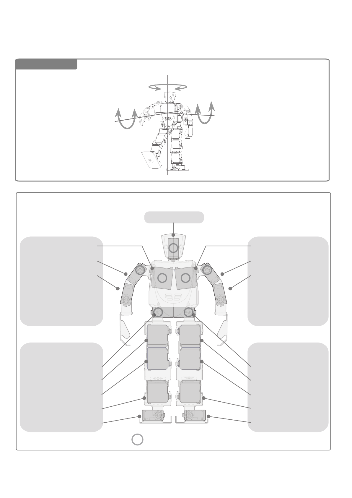
Servo Motor Mounting Positions
1919
Name of Axes
Vertical Axis: Yawing Axis
Horizontal Axis: Pitch Axis
Longitudinal Axis: Roll Axis
CN5
CN3
S6: Right Shoulder Pitch Axis
S5: Right Shoulder Roll Axis
S4: Right Elbow Roll Axis
S3:
S2:
S1: Right Eye LED
CN1
S6:
S5: Right Thigh Roll Axis
S4: Right Thigh Pitch Axis
S3: Head Yawing Axis
S
S S
S
S S
S
CN4
S6: Left Shoulder Pitch Axis
S5: Left Shoulder Roll Axis
S4: Left Elbow Roll Axis
S3:
S2:
S1: Left Eye LED
CN2
S6:
S5: Left Thigh Roll Axis
S4: Left Thigh Pitch Axis
S3: Right Below Knee Pitch Axis
S2: Right Ankle Pitch Axis
S1: Right Ankle Roll Axis
S
: Use a short cable
S3: Left Below Knee Pitch Axis
S2: Left Ankle Pitch Axis
S1: Left Ankle Roll Axis

2020

7-1 Assembling the Right Arm
2121
Prepare the required parts.
(a 2202)
(a 2201)
R
VS-X Servo Holder A
( a 2202- a 2201 )
Long Cable 40 cm
Servo Motor VS-S092J
*Confusion of M2-4 and M2-5 screws may damage the robot.
M2-
4
T
M2-
Screw F,
M2-4 Flat Head Tapping
5
Screw E,
M2-5 Flat Head Tapping
VS-X Bracket B
(a 3302)
*This is not a VS-X bracket A.
Short Cable 15 cm
T
Screw C,
M3-5 Flat Pan Head Cap
M3-
Standard Hand Bracket A
(a 3301R)
Servo Horn
5
8
T
M3-
Screw H,
M3-8 Flat Head Tapping
Friction Rubber
Bush
(1) Right Arm

01. Assembling the Right Wrist
2222
M2-
5
T
02. Assembling the Upper Right Arm
< Hand Side >
M2-
5
T
Reverse
M2-
T
5
:Screwing spot
< Shoulder Side >
Short Cables
03. Mounting the Right Elbow Roll Axis
M3-
5
M2-
4
T
M3-
8
T
Short Cables
Friction Rubber Bush
Origin
*Use the tapped holes as a reference.
< Frame Mounting Position against the Origin >
90o or More
Until Contacting
Checking the Movable Range

7-2 Assembling the Left Arm
2323
Prepare the required parts.
(a 2202)
VS-X Servo Holder A
(a 2202- a 2201)
Long Cable 40 cm
x1
(a 2201)
*This is not a VS-X bracket A.
Short Cable 15 cm
Servo Motor VS-S092J
VS-X Bracket B
(a 3302)
x1
x1x1
x1
L
Standard Hand Bracket A
(a 3301L)
x2
Servo Horn
*Confusion of M2-4 and M2-5 screws may damage the robot.
M2-
4
Screw F,
M2-4 Flat Head Tapping
M3-
8
Screw H,
M3-8 Flat Head Tapping
x3
x1
M2-
5
Screw E,
M2-5 Flat Head Tapping
x16
x1 x1
M3-
5
Screw C,
M3-5 Flat Pan Head Cap
x1
Friction Rubber
Bush
(2) Left Arm

01. Assembling the Left Wrist
2424
02. Assembling the Upper Left Arm
M2-
5
T
<Hand Side>
M2-
5
T
T
M2-
5
Reverse
<Shoulder Side>
Short Cables
03. Mounting the Left Elbow Roll Axis
Screwing spot
Origin
Bush Friction Rubber
M3-
5
90o or More
M2-
4
M3-
Short Cables
T
8
T
45°
*Use the tapped holes as a reference.
<Frame Mounting Position against the Origin>
Until Contacting
Checking the Movable Range

7-3 Assembling the Right Leg
2525
Prepare the required parts.
VS-X Bracket A
(a 2101)
*This is not a VS-X bracket B.
(a 2202)
VS-X Servo Holder A
(a 2202- a 2201)
x4
(a 2201)
x1
VS-X BracketC
(a 2301R)
VS-X Servo Holder B
(a 2502)
x1
R
Standard Sole Set A
(a 2501)
VS-X Servo Holder C
(a 2302)
Long Cable 40 cm
Servo Motor VS-S092J
*Confusion of M2-4 and M2-5 screws may damage the robot.
M2-
3
Screw A,
M2-3 Flat Pan Head
M3-5
Screw C,
M3-5 Flat Pan Head Cap
M2-
Screw F,
M2-4 Flat Head Tapping
M3-
Screw H,
M3-8 Flat Head Tapping
Short Cable 15 cm
4
T
T
8
Servo Horn
5
T
M2-
Screw E,
M2-5 Flat Head Tapping
Friction Rubber
Bush
(3)Right Leg

01. Assembling the Right Sole
2626
M2-
3
02. Mounting the Servo to the Right Sole
<Top View>
Reverse
M2-5 M2-5
T T
<Front>
<Rear>
03. Assembling the Orthogonal Parts
M2-
5
T
Pay attention to the assembling direction.
: Screwing spot

04. Mounting the Right Ankle Roll Axis
2727
M3-
M2-
4
T
M3-
8
T
5
Friction Rubber Bush
Origin
<Frame Mounting Position against the Origin>
05. Assembling the Right Below Knee Parts - 1
右脛部の作成1
M2-
5
T
Until Contacting
Checking the Movable Range
:Screwing spot

2828

2929

10. Assembling the Orthogonal Parts
3030
T
M2-
5
Pay attention to the assembling direction.
11. Assembling the Right Thigh Pitch Axis
11
:Screwing spot
M2-
4
T
Bush Friction Rubber
Middle Point of Two Holes
Origin
M3-
8
M3-
5
T
<Front> <Rear>
Until Contacting
90o or More
<Front> <Rear>
< Frame Mounting Position against the Origin >
<Front> <Rear>
Checking the Movable Range

7-4 Assembling the Left Leg
3131
Prepare the required parts.
L
VS-X Bracket A
(a 2101)
*This is not a VS-X bracket B.
(a 2202)
VS-X Servo Holder A
( a 2202- a 2201)
Long Cable 40 cm
Servo Motor VS-S092J
(a 2201)
VS-X Bracket C
(a 2301L)
VS-X Servo Holder B
(a 2502)
Short Cable 15 cm
Standard Sole Set A
(a 2501)
VS-X Servo Holder C
(a 2302)
Servo Horn
*Confusion of M2-4 and M2-5 screws may damage the robot.
M2-
3
Screw A,
M2-3 Flat Pan Head
M3-5
Screw C,
M3-5 Flat Pan Head Cap
Friction Rubber
M2-
4
T T
Screw F,
M2-4 Flat Head Tapping
M3-
8
T
Screw H,
M3-8 Flat Head Tapping
Bush
M2-
5
Screw E,
M2-5 Flat Head Tapping
(4) Left Leg

01. Assembling the Left Sole
3232
M2-
3
02. Mounting the Servo to the Left Sole
<Top View>
Reverse
M2-
5
T T
M2-
5
< Front > < Rear >
03. Assembling the Orthogonal Parts
M2-
5
T
Pay attention to the assembling direction.
:Screwing spot

04. Mounting the Left Ankle Roll Axis
3333
M3-
5
Bush Friction Rubber
M2-
4
T
M3-
8
T
Origin
< Frame Mounting Position against the Origin >
05. Assembling the Left Below Knee Parts - 1
M2-
5
T
Until Contacting
Checking the Movable Range
:Screwing spot

3434

3535

3636

7-5 Assembling the Body
3737
Prepare the required parts.
Front Body Frame
Body Shoulder Frame
(a 1101)
Rear Body Frame
(a 1102)
Body Side Frame
*(a 1103)
(a 1107) (a 1106)
Battery Storage Door
Upper Body Frame
VS-X Standard Body Set
(a 1104)
(a 1105)
Power Connector Holder
One Each
*(a 1103)x2
Long Cable 40cm
Servo Motor VS-S092J
Short Cable 15cm
Servo Horn
(To Be Continued)

CPU Board
3838
VS-RC003HV
Power Cable
(Optional Part)
Speaker
Game Pad Conversion Connector
Gyro Sensor/Acceleration Sensor Extension Board
VS-IX001
M2-
Spacer A,
M2-3 (Hexagonal Spacer)
*Confusion of M2-4 and M2-5 screws may damage the robot.
M2-
Screw A,
M2-3 Flat Pan Head
S S
3
3
M2-
5
Spacer B,
M2-5 (Hexagonal Spacer)
M2-
Screw F,
M2-4 Flat Head Tapping
T T
4
M2-
Screw E,
M2-5 Flat Head Tapping
Urea Resin Screw
5
Nut for Urea Resin Screw
M3-5
Screw C,
M3-5 Flat Pan Head Cap
Bush
M3-
Screw H,
M3-8 Flat Head Tapping
*Four of them are for the optional part.
T B
8
M2-
4
Screw G,
M2-4 Bind Tapping
(Continued from Previous page )
(5) Body

3939

04. Mounting the Power Connector Holder
4040
M2-
3
<Pay attention to the mounting direction.>
05. Mounting the Game Pad Conversion Connector
M2-
3
10-Core Connector Mounting Position
M2-
3
M2-
3
06. Assembling the Shoulder
M2-
5
T
S
07. Assembling the Shoulder
M2-
3
Assemble 2 units.
Pass a cable
between the servos.

08. Mounting the Speaker
4141
Mounting the Gyro Sensor (Optional)
M2-
B
4
09. Mounting the Body Side Frame
M2-
3
CTS
ON
1
2 3 4
Set all the switch segments
to the numerical side (OFF).
( Optional Part )
The robot automatically balances itself to prevent tumbling.
M2-
10. Mounting the Spacer to the CPU
M2-
S
5
3
Gyro Sensor/Acceleration Sensor Extension Board
VS-IX001
M2-
3
Pay attention to the mounting position.
Use outside holes.

11. Connecting the Power Cable
4242
Gyro Sensor Cable (Optional)
Power Switch
Speaker Cable
Pass it under the power cable
(head side).
Power Connector (Battery Side)
Power Connector
Game pad Conversion Connector Cable
12. Mounting the Switch
(The cordless side is outside)
M2-
Routing the 10-Core Cable
13. Mounting the CPU
3
Gyro Sensor Cable
(Optional)
M2-
3
Game Pad Conversion Connector Cable
Speaker Cable
(Pass the cable)

14. Mounting the Rear Frame
4343
M2-
3
M2-
5
T
Lead out shoulder pitch axis cables
from the top and thigh roll axis cables
from the bottom.
15. Mounting the Battery Storage Door
M3-
5
Bush
Ensure that the power cable is not caught
between the CPU and the servo motor.
< Top View >
Secure firmly with cutting pliers
so that it will not come off.
Urea Resin Screw
Nut for Urea Resin Screw
The grooved side is upward.
M3-
Bush
The shoulder is opened and closed
5
depending on tightness of the urea resin screw.

7-6. Mounting the Arms and Legs to the Body (1)
4444
Mounting the Right Arm
Prepare the required parts.
VS-X Bracket A
( a 2101 )
*This is not a VS-X bracket B.
Servo Horn
*Confusion of M2-4 and M2-5 screws may damage the robot.
M3-
M2-
4
Screw F,
M2-4 Flat Head Tapping
Friction Rubber
5
Screw C,
M3-5 Flat Pan Head Cap
Bush
Screw H,
M3-8 Flat Head Tapping
M3-
8
DURACON Washer
(6) Mounting the Right Arm

01. Mounting the Right Arm - 1
4545
M2-
4
T
M3-
8
T
DURACON Washer
< Rear >
< Mounting Position against the Origin >
Origin
< Front >
90o or More 90o or More
Checking the Movable Range

4646

4747

01. Mounting the Left Arm - 1
4848
DURACON Washer
M3-
M2-
4
T
8
T
< Front >
< Mounting Position against the Origin >
Origin
< Rear >
90o or More 90o or More
Checking the Movable Range

4949

7-6. Mounting the Arms and Legs to the Body (3)
5050
Mounting the Right Leg
Prepare the required parts.
Servo Horn
*Confusion of M2-4 and M2-5 screws may damage the robot.
M2-
4
T
Screw F,
M2-4 Flat Head Tapping
Friction Rubber
M3-
5
Screw C,
M3-5 Flat Pan Head Cap
Bush
8
T
M3-
Screw H,
M3-8 Flat Head Tapping
(6) Mounting the Right Leg

01. Mounting the Right Leg
5151
M2-
M3-
8
T
4
T
M3-
5
Origin
Friction Rubber Bush
Until Contacting
90o or More
< Mounting Position against the Origin >
Checking the Movable Range

5252

01. Mounting the Left Leg
5353
M3-
8
T
M2-4
M3-
T
Bush Friction Rubber
5
Origin
< Mounting Position against the Origin >
Until Contacting
90o or More
Checking the Movable Range

7-7. Checking the Movable Ranges (1)
5454
Head and Right Arm
Rear
90o or More
Rear
90o or More
90o or More
Front
Front
S6: Right Shoulder Pitch Axis
S5: Right Shoulder Roll Axis
S4: Right Elbow Roll Axis
90o or More
: Use a short cable
S
S3: Head Yawing Axis
S
S S
S
S
Until Contacting
90o or More
S S
90o or More
90o or More
(Warp the elbow outside)

5555

5656

5757

7-8. Wiring and Mounting the Head Armor (1)
5858
Wiring
Prepare the required parts.
M2-
3
Screw A,
M2-3 Flat Pan Head
Binding Band
Binding Band Washer

It is recommended to mark the connectors so that you can easily tell where they should be used.。
5959
01. Wiring the Arms
Binding Bands Binding Bands
Washers
From above the wiring
M2-
3
M2-
5
T
Binding Bands
From below the wiring
M2-
5
< How to Secure with the Binding Bands >
T
Prior to securing the wiring with the binding bands,
remove the relevant screws already attached in the previous assembly process.

02: Wiring the Legs
6060
M2-
3
Binding Band
Washers
5
T
M2-
Binding Band
Washers
From behind the wiring
Wire the left leg in the same manner.
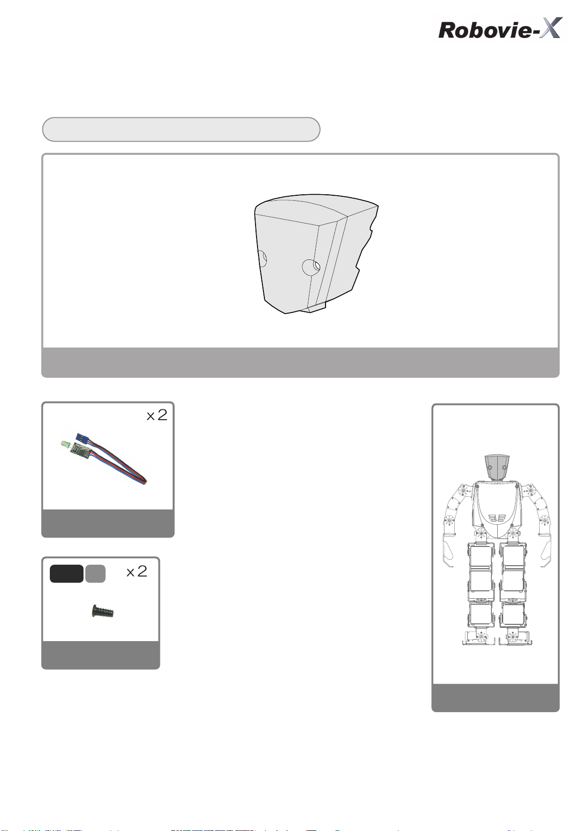
7-8. Wiring and Mounting the Head Armor (2)
6161
Mounting the Head Armor
Prepare the required parts.
One Each
Rear of HeadFront of Head
LED Board
M2-
5
Head Rear Armor Head Front Armor
VS-LED1
T
Screw E,
M2-5 Flat Head Tapping
(8) Head

01. Mounting the Head Armor
6262
01
Mount it so that the cables will face inside.
M2-
5
T
M2-
5
T

Wiring to the CPU
6363
Wire all the servo motors and LEDs.
The following shows a connection diagram.
Seeing the figure below, connect the servo motor cables to the CPU.
*Prior to connecting, check a connecting position fully.
CPU ( VR-RC003HV ) Connection Diagram
Note that erroneous wiring may damage the CPU or the servo motor.
Rotary Switch
USB
S6: Left Shoulder Pitch Axis
S5: Left Shoulder Roll Axis
CN4
S4: Left Elbow Roll Axis
S3:
S2:
S1: Left Eye LED
S6:
S5: Left Thigh Roll Axis
S4: Left Thigh Pitch Axis
S3: Left Below Knee Pitch Axis
CN2
S2: Left Ankle Pitch Axis
S1: Left Ankle Roll Axis
Condenser
*S1, S2, and so on from the power source side (right)
CN1 to CN5: Servo motors, VS-LED 1
CN6: Controller
CN11: Speaker
CN7: IXBUS (for an extension board)
CN6CN7
CN11
VS-RC003D
CN5
Head Yawing Axis
<Cable Direction>
CN3
CN1
Power Connector
S6: Right Shoulder Pitch Axis
S5: Right Shoulder Roll Axis
S4: Right Elbow Roll Axis
S3:
S2:
S1: Right Eye LED
S6:
S5: Right Thigh Roll Axis
S4: Right Thigh Pitch Axis
S3: Right Below Knee Pitch Axis
S2: Right Ankle Pitch Axis
S1: Right Ankle Roll Axis
S6: Right Shoulder Pitch Axis
S5: Right Shoulder Roll Axis
S4: Right Elbow Roll Axis
S3:
S2:
S1: Right Eye LED
S6:
S5: Right Thigh Roll Axis
S4: Right Thigh Pitch Axis
S3: Right Below Knee Pitch Axis
S2: Right Ankle Pitch Axis
S1: Right Ankle Roll Axis
S3: Head Yawing Axis
S
S S
S
S
S S
S
: Use a short cable
S6: Left Shoulder Pitch Axis
S5: Left Shoulder Roll Axis
S4: Left Elbow Roll Axis
S3:
S2:
S1: Left Eye LED
S6:
S5: Left Thigh Roll Axis
S4: Left Thigh Pitch Axis
S3: Left Below Knee Pitch Axis
S2: Left Ankle Pitch Axis
S1: Left Ankle Roll Axis

7-9. Mounting the Body Armor
6464
Prepare the required parts.
Body Front Armor
4
B
M2-
Screw G,
M2-4 Bind Tapping
One Each
Body Rear Armor
(9) Armor (Chest)

01. Mounting the Armor Panel (Rear)
6565
M2-4
B
Bundle the cables in the rear and mount the armor.
When this is done, ensure that they are not caught.
If they are bundled too short,
they will not only hinder robot movements,
but damage the servo motors or cause snapping
or short-circuit.
<Wiring Example>
When the gyro sensor* is mounted;
When the gyro sensor is mounted,
bundle its wiring in the center as well.
(* Optional)
<Wiring Example>
Bundle the cables in the center of the body
so that they will not be caught
between the armor and the aluminum parts.

02. Mounting the Armor Panel (Front)
6666
M2-4
B
Mount a receiver for a radio game pad,
if required, prior to mounting the armor.

Wiring Check
6767
If the cables are bundled too short in the rear, they will not only hinder robot movements,
but damage the servo motors or cause snapping or short-circuit.
If they are slackened too much, the robot will be caught by them,
damaging the servo motors or causing snapping or short-circuit.
Move each of the robot joints to recheck whether or not the cables are too tight.
The following checks the noteworthy areas.
03. Wiring Check (Neck)
Oscillate the neck to the right and left to check whether or not the cables are too tight.

04. Wiring Check (Shoulder)
6868
Place the arms in this condition and check whether
or not the cables hinder arm movements.
Check the right and left arms.
Move the arm forward by 90o.
Move the arm backward by 90o.

7-10. Pasting the Sole Tape
6969
Prepare the required parts.
Sole Tape
Pasting the sole tape produces adequate friction with the ground,
allowing the robot to move stably.
01. Pasting the Sole Tape
Paste the tape free from air bubbles or wrinkles
and cut it with scissors along the soles.

8. INSTALLATION OF BATTERY
7070
Check: Check whether or not the power switch of the robot body
has been turned to OFF (outside).
• Loosen the urea resin screw to install the battery in the body.
• Install it so that the power cable will be routed on the battery inserting side
and the front side of the robot.
• If the internal wiring is messed up, the battery may not be properly installed.
• Tidy up the wiring to install the battery. Tighten the urea resin screw firmly so
that the battery will not come out while the robot is operating. Be careful not to
tighten it too hard.
To removing the battery, hold down a pawl on its connector and pull out the
connector. Do not pull its cable.
If you notice a foul odor or excessive heat generation,
turn off the switch immediately and remove the battery.
Now, you are ready to operate the robot.
Proceed to “Robovie-X Software Reference.”

9. INQUIRIES ABOUT TROUBLES,
7171
MISSING PARTS, DAMAGE, ETC.
•About Missing and Defective Parts
For missing and defective parts, check the relevant part names with the List of Parts Used. We will
replenish or replace them. (Contact us by e-mail, fax, telephone or letter.)
•When You Suspect a Trouble
In case the robot cannot be properly assembled or operated, let us know a phenomenon in details
by e-mail, telephone, fax or letter. We will investigate the case and contact you.
Vstone Co., Ltd.
E-mail: infodesk@vstone.co.jp
Phone: 06-6467-6601 Fax: 06-6467-6602
Address: 4-4-11 Shimaya, Konohana-ku, Osaka, 554-0024
URL: http://www.vstone.co.jp/
Office hours: 9:00 to 12:00 and 13:00 to 18:00
on Monday thru. Friday (except holidays)
User Support Service
User Support Service
Shop Support Service (Irregular, Free of Charge)
Venue: Osaka (Nipponbashi), Tokyo (Akihabara)
To be informed prior to implementation at http://www.vstone.co.jp/
Manufacturer’s robot specialty shop
“ROBO-PRO Shop” (Fukuoka, Kyushu)
2-3-2 Momochihama, Sawara-ku, Fukuoka, Fukuoka Pref., 814-0001
TVC Housoukaikan 2 Fl., Robo Square
Phone: 092-821-4111
URL: http://www.vstone.co.jp/roboproshop/
Community Space for Robot Users “ROBO-PRO Station”
(To be held monthly in Osaka and Tokyo)
A full-fledged robot fighting ring and a football field will be provided in addition to
user support. Machining tools will be also available.
For details, see our URL (http://vstone.co.jp/top/robo-prostation/
.
).
*The services above are subject to change or termination without prior notice.

APPENDIX: EXTENSION OF FUNCTIONS
7272
Mounting the Optional Part
An optional extension board can be mounted to the back of Robovie-X.
M2-
The extension board allows addition of LEDs or
more advanced programming such as reading
the information of a distance sensor, switch, etc.
into Robovie-X to behave according to the
circumstances.
3
<Mounting the Extension Board VS-IX Series>
*If the VS-IX001 (gyro/acceleration sensor extension board) is mounted to the back,
the robot will not function properly. Seeing Page 41, mount it inside the body.
Extension Board "VS-IX" Series
Gyro/Acceleration Sensor Extension Board
This subminiature extension board has a 2-axis
gyro sensor and a 3-axis acceleration sensor
mounted onto it. Robot posture control by the
gyro sensor, and the acceleration sensor are
capable of detecting tumbling of the robot and
[Major Specifications]
Dimensions:25mmx30mm
Sensors mounted:
2-axis gyro sensor, 3-axis acceleration sensor
(Tax included)
Digital I/O Extension Board
LED Extension Board
This extension board is capable of control 16
channels of LEDs. It can use of PWM to control
the LEDs, and set their brightness in 256
stages.
[Major Specifications]
Dimensions:25mmx30mm
LED control line: PWM system, 2 channels
LED output: 16 channels
(Tax included)
Analog Input Extension Board
(Tax included)
This extension board is equipped with 16
channels of digital I/O ports. A switch can be
connected to digital input to detect an obstacle
and change the advancing direction, or a LED
is connected to digital output to light it up.
[Major Specifications]
Dimensions:25mmx30mm
Digital I/O: 16 channels
(8 channels x 2, shared by the I/O ports)
This extension board is equipped with 8
channels of analog input ports. A PSD sensor,
etc. can be connected to feed back motion and
posture signals to the servo motors, etc.
according to the sensor information.
[Major Specifications]
Dimensions:25mmx30mm
Analog input: 8 channels
(Tax included)
 Loading...