

Page 1
Vstone Co.,Ltd.
ATR
Page 2

1
0.Introduction
Please Read First
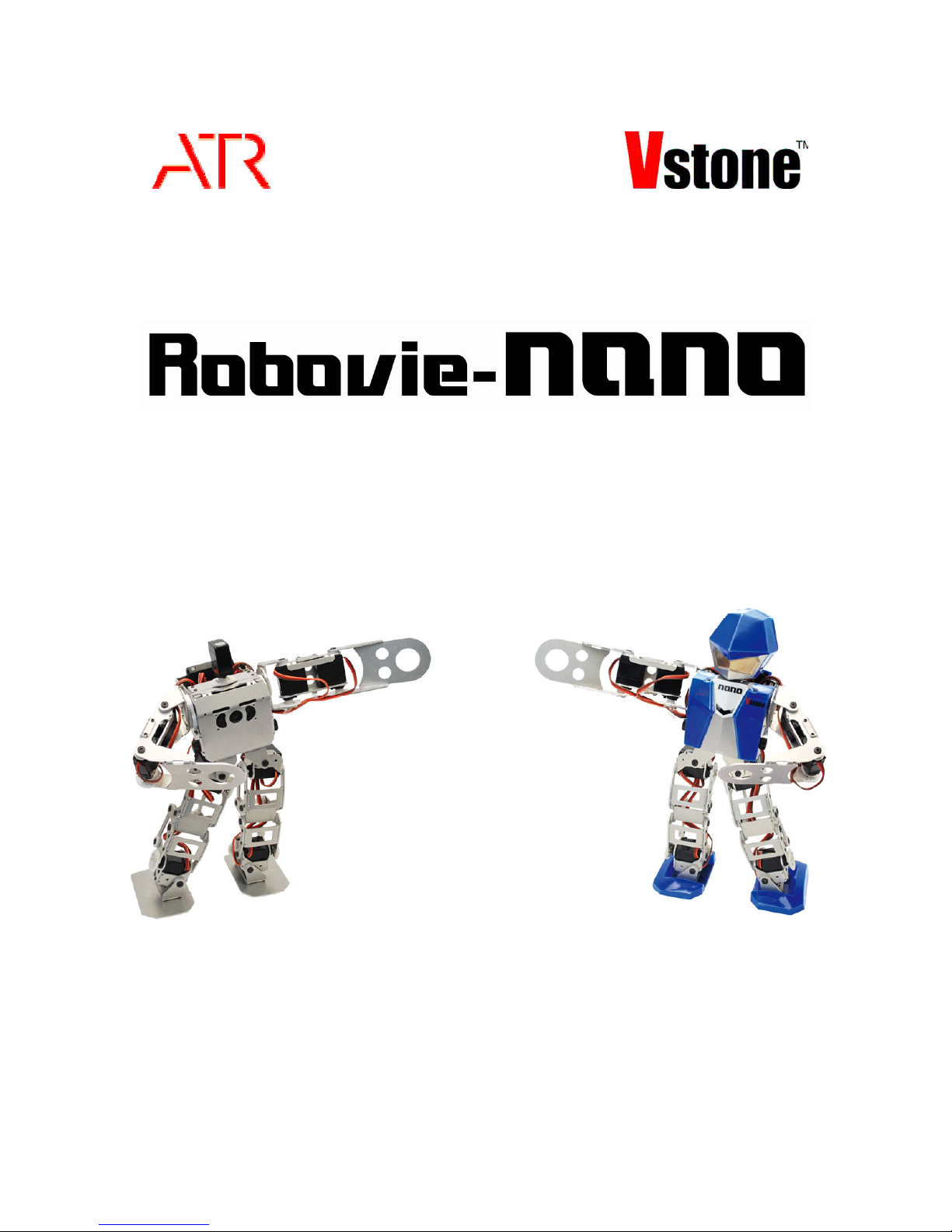
Thank you for purchasing the Robovie-nano bipedal robot kit. Contained herein are the
directions for assembling the robot kit. Please carefully follow the instructions and have fun.
This is a do it yourself assembly kit. The quality of the end product will vary depending on how
the robot is assembled by the user, so careful attention must be followed to following the
directions. Please do not hesitate to seek assistance if any problems arise during the course of
the assembly.
After assembling the robot, a personal computer (PC) will be required for programming
purposes. A software usage guide is included with the kit, however, the manufacturer will not be
able to answer any Windows specific questions. A working level knowledge of PCs is assumed
from this point forward.
A battery charger is not included with this kit, however 4 AA batteries are required for operation,
so it is recommended that the user purchase rechargeable Ni-MH batteries and an off the shelf
battery charger.
※ Please note that the specifications listed herein are subject to change without advanced
notice, in order to enhance performance of the Robovie-nano system.
Page 3

2
Safety Warnings
●As for this product、this is a do it yourself robot kit so much of the stated performance in this
manual cannot guaranteed, due to the nature of varying methods of user assembly..
●Please do not use of this product、assemble、or store parts around small children、This kit
contains small pieces which may be easily swallowed.
●This product is not a toy. If shown in front of kids, always make sure an adult is present.
●The product can get damaged or ruined is left in areas of high moisture, humidity or
condensation.
●Please use adequate safety measures and techniques when using tools.
●Please do not modify or alter any of the circuitry or electrical components. This could result in
equipment failure, electric shock, or even fires.
●Do not apply any foreign objects, especially metals or substrates to the electronic circuitry. This
could result in equipment failure, electric shock, shorts or even fires.
●Please prepare adequate table space when assembling, programming and testing the robot.
During programming, the robot can suddenly move and knock items over, and possibly cause
personal injury to the user or anyone nearby due to high torque servo motors and sharp
brackets.
●Please check the polarity of the connectors. Fire and other hazards may occur if installed
incorrectly.
●Please be careful to avoid crimping the cables in the robot frame. Short can occur.
●Please remove all cables and connectors at the plug end. Failure to do so could tear the wire
and lead to shorts or fires.
Page 4

3
About the Servo Motors
A servo motor has an important rule and concept concerning its mounting. If it is mounted in a
wrong way, the robot will not move correctly. When assembling the servo motor, read this page
thoroughly.
○Servo motor original position
The servo motor is controlled by the CPU and can be programmed by the user to freely run.
The servo motor VS-S020 used for the Product has frame mounting holes in the top and back
covers, into which a frame is mounted. Then, mount a servo horn to an output shaft (power
supplied shaft), followed by the frame there, to use it as the robot’s joint. A movable range of the
robot’s joint depends on this mounting of the servo horn.
The servo motor has its movable range. The VS-S020 used for the Product moves within a
range of about 130º, that is from -65º to +65º.* The central position of 0º is called the “origin.”
each servo motor has a slight angle discrepancy. Even if the angle of the origin is sent from the
CPU board to the servo motor, it may be slightly dislocated from the origin. Assuming that the
origin position based on a signal from the CPU board is correct, this robot uses software to adjust
an error produced in the actual servo motor. (An error adjusting method is described later.) In
the following description, “origin” is used as the “origin set by the CPU board.”
○Mounting a servo horn
A servo horn mounting angle to the origin is important in order to set a movable range of the joint
more accurately. If the origin is not accurately set, the robot cannot move successfully in
motions, such as getting up, which require an accurate movable range. Try each hole in the
servo horn one after another until it is located at the most accurate angle to the origin. When
mounting the servo horn to the output shaft, do not allow the servo motor’s output shaft to be
rotated.
○About “motor lock.”
Some servomotor can not rotate in 130º by some joint frame. We limit the rotating range in
software, however we can not limit the rotating range perfectly at the legs and arms.
If a hand or a foot gets caught on the body at the time of activating the servo motors, an
excessive load will be applied to the servo motors. This condition is called “motor lock.” If
this condition persists, the servo motors will be heated and go out of order(breaking
gear/case/servo circuit board/CPU board ). While compensating, touch the servo motors
periodically with your hand to check if they are heated. If they are too hot to touch, turn off
the Power switch of the Robot immediately and wait until the servo motors are cooled down.
Please be careful of Motor lock.
Page 5
4
1.Equipment
Please prepare the following tools and have readily available during and after assembling the
robot.
●Personal Computer
CPU:Pentium 3 or equivalent (1GHz or Greater)
RAM:128MB
OS:Windows 2000/XP/Vista
Display:XGA or Better
Interface:USB
CD-ROM Drive Installed。
●Tools
・Screw Drivers
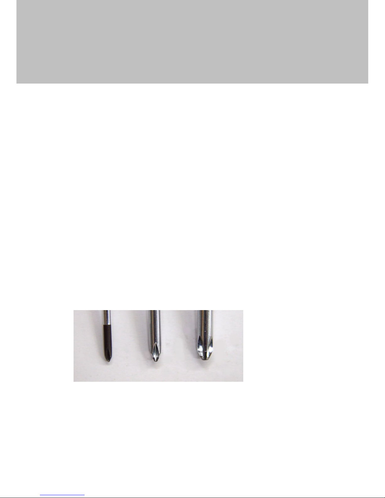
#0、#1 Philips (#2 cannot be used)
●Other useful items
Screwdriver, tweezers, towels, cellophane tape, bowl for screws
#0 #1 #2
Screws A,B Screws C,D,E,F Do Not
Page 6
5
2.Parts Discription
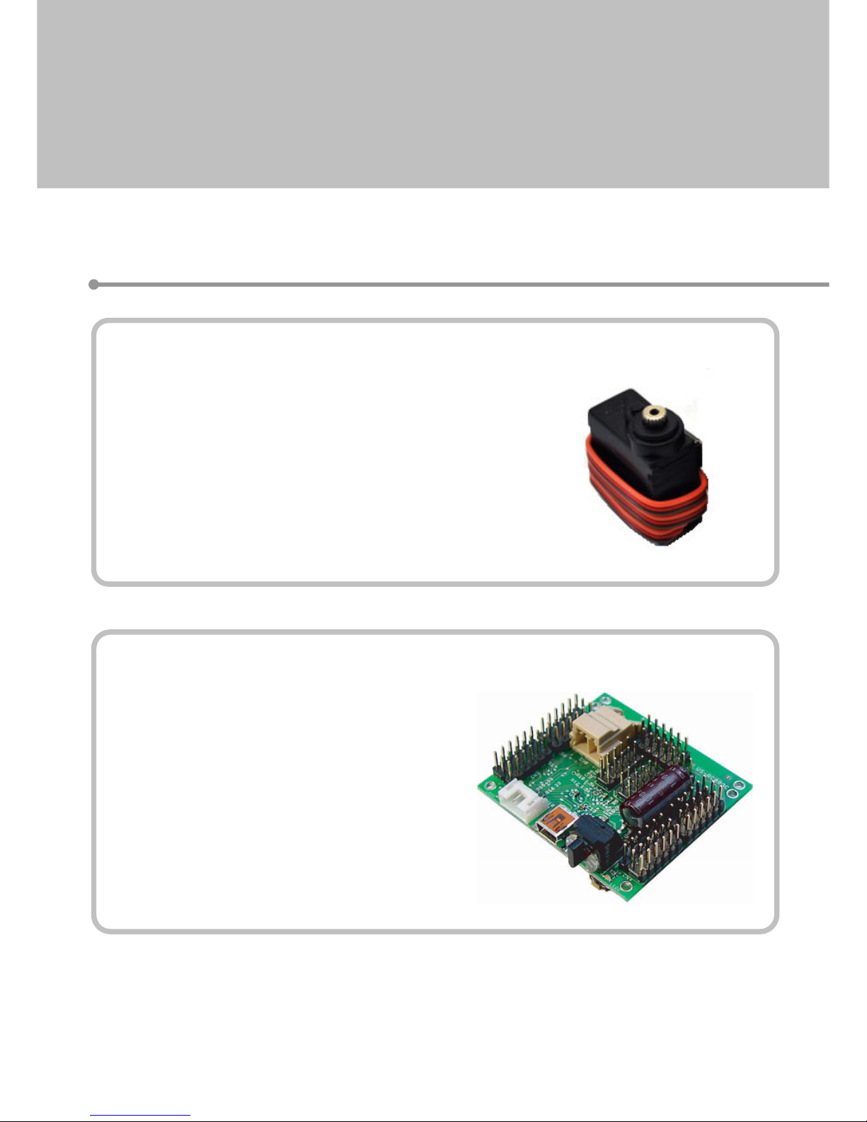
・Servo Motor VS-S020
Dimensions:22.5×11.5×24.6mm(L×W×H)
Torque:2.2kg・cm
Speed:0.11S/60°
Weight:12g
Range of Motion:140°
Electrical Input:4.8V~6V(7.4V Optimal)
Protocol:PWM
・Robot Internal CPU Board VS-RC003HV
Dimensions: 52x48(44)x13mm
Weight: 21g
Servo Motor Output:30ch
Voice/Sound Output:2W
Electrical Input: 5V~16V
PC interface:USB (HID)
Remote Control: PS2 Wireless Remote, Probo
Expansion Boards:IXBUS × 1
Included Parts
Page 7
6
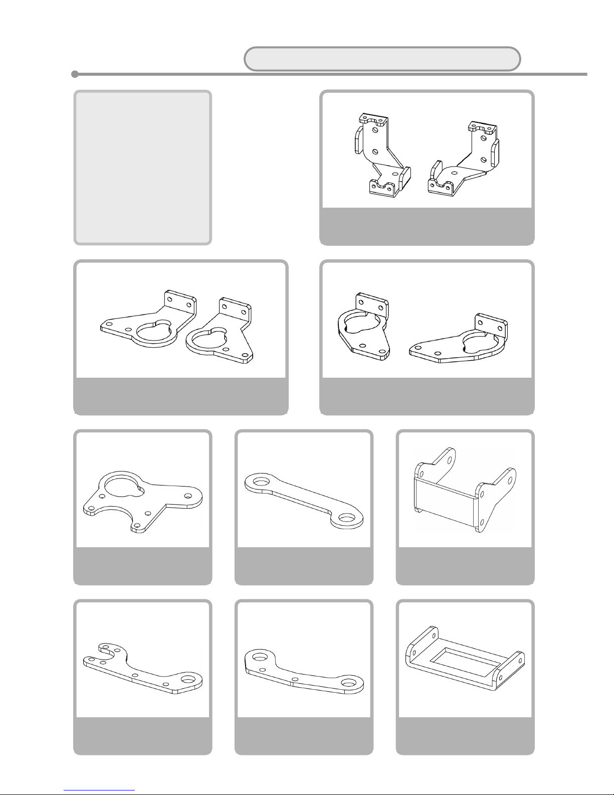
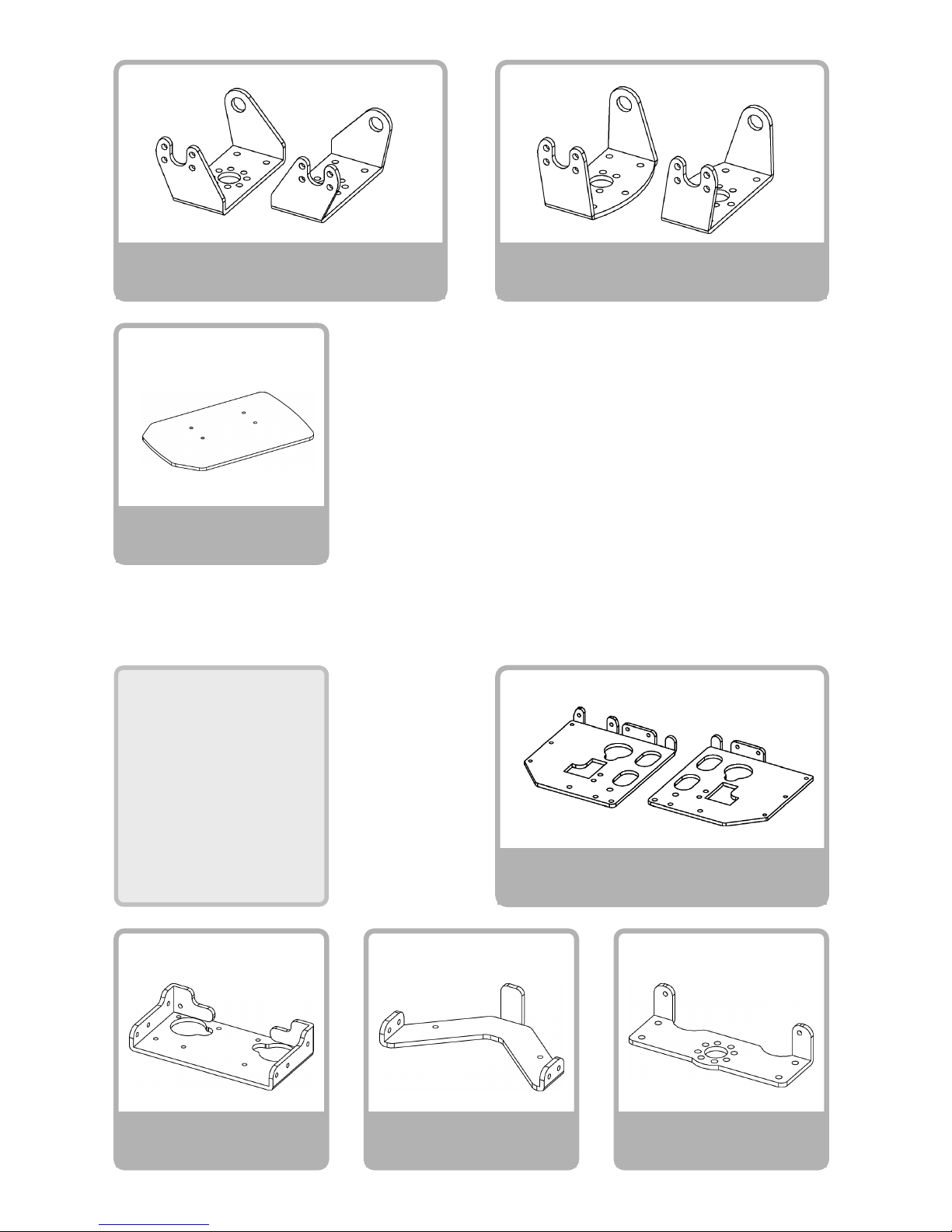
Servo Holder A
× 2 each
Knee Frame
×2
Servo Holder C
X 1 each
Servo Holder B
X 1 each
Servo Holder D
×4
Link Arm A
×4
Link Arm C
×4
Link Arm B
×4
Rear Link Arm
×4
Parts List
Please confirm all parts are included in kit
Main Body
Frame
<L>
<L> <L><R> <R>
<R>
Page 8
7
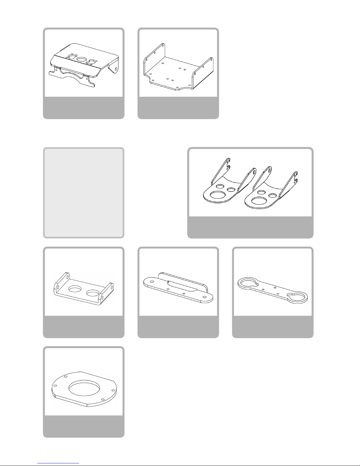
Top Frame
×1
Foot
×2
Bottom Frame
×1
Battery Box Frame
×1
Bracket A
X 2 each
Bracket B
X 1 each
Side Frame
X 1 each
Body
Frame
<L> <L><R> <R>
<L> <R>
Page 9
8
Front Cover
×1
Back Cover
×1
Arm HolderB
×2
Arm HolderC
×2
Arm Holder A
×2
Hand Frames
×1each
Arm
Frames
Flat Washer
×2
<L> <R>
Page 10
9
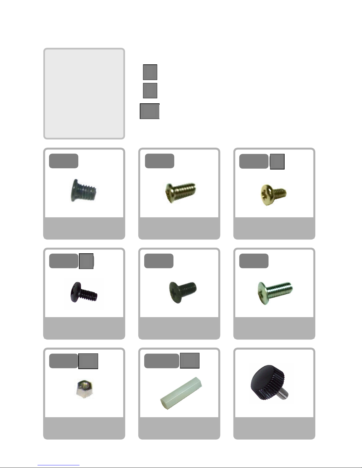
Screw NA
M2-3 Course Thread
×102
3
M2-
4
M2-
5
M2-
4
M2-
S
バ
Spacer A
M2-3(Hex spacer)
×2
6
M3-
Screw NF
M3-8 Fine Thread
×4
8
M3-
Twist Screw
×2
Spacer C
M3-20(Hex Spacer)
×2
3
M2-
ス
20
M3-
バインドネジ
Screw NB
M2-4 Course Thread
×4
Screw ND
M2-5 Binding
×10
Screw NC
M2-4 S Tight
×75
Screw NE
M3-6 Fine Thread
×24
ス
Screw
Varieties
B
S
Sp
Binding Screw
S Tight Screw
Spacer
S
B
Sp
Sp
Page 11
10
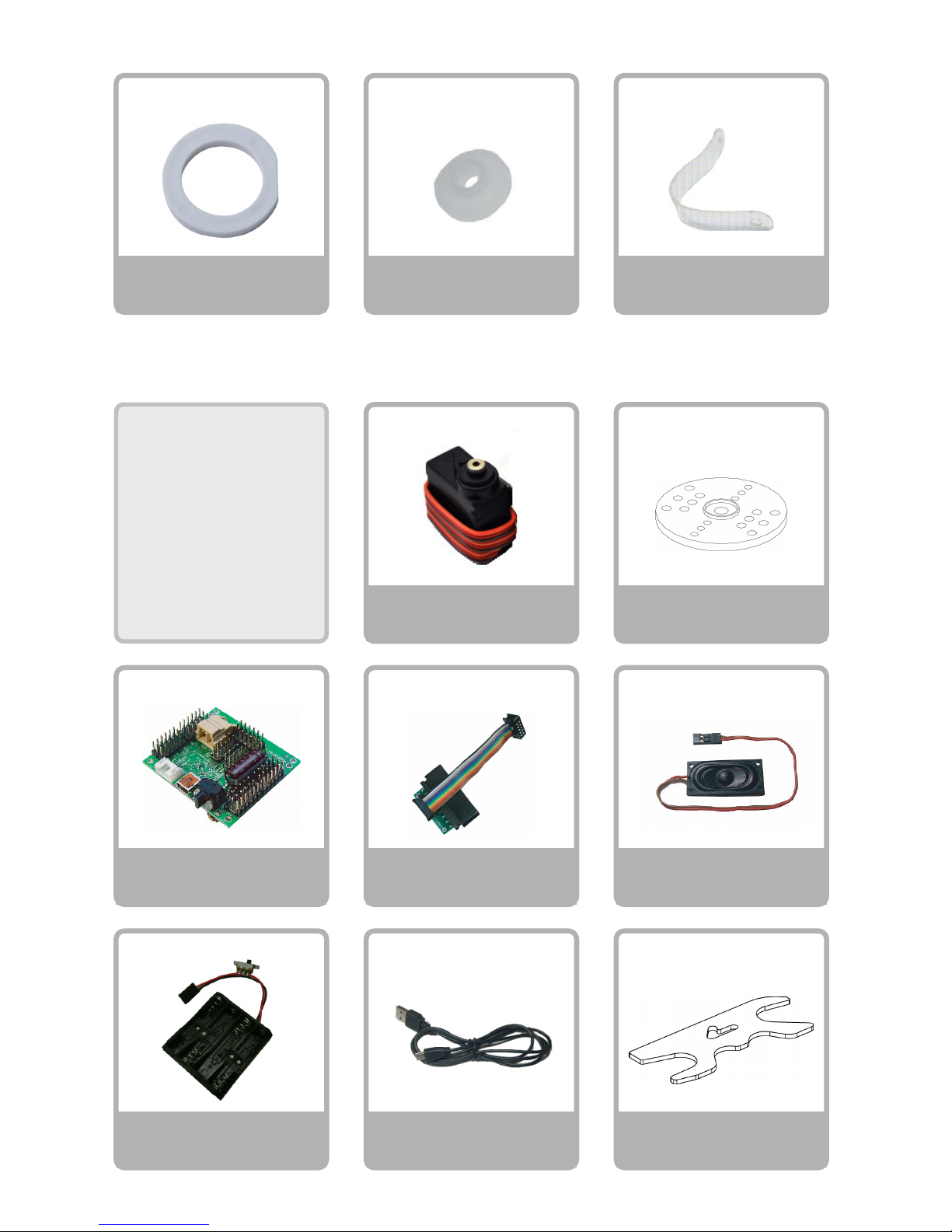
Speaker
×1
USB Cable
×1
Connector and Cable
Gamepad Receiver
×1
CPU Board
VS-RC003HV
×1
Servo Motors
VS-S020
×15
Battery Terminal
×1
VS-S020
Servo Horn
×15
Washer
×28
Washer Bearing
×2
Major
Parts
Cable Ties
×10
Initial Position
Adjustment Jig
×1
Page 12

11
3.Assembly
Important Points
・Please use new screw driver.
Philips head screwdriver #0: M2‐3 Course thread, M2‐4 course thread.
Flat head screwdriver #1: M2‐4S tight、M2‐5 Binding、M3‐6、M3‐8 screws.
・Please make sure to use correct screw type.
In particular, M2-4 tapping screws and M2-5tapping screws are very similar. Please note
that if you use M2-5 tapping screw for the output shaft of the servo, it may case a
malfunction of the robot.
・Please install the servo horn in specified center position.
When installing the servo horn to servo, please try several times until you find the
center position. If you install the servo horn in wrong position, the robot may not be
able to play motions properly.
Assembly Instructions
Please follow the following instruction in order.
① Setting up servo motors
② Assembling right leg
③ Assembling left leg
④ Assembling right arm
⑤ Assembling left arm
⑥ Assembling Body
⑦ Attaching legs and arms onto the body
⑧ Wiring
⑨ Attaching covers onto front and back
Page 13
12
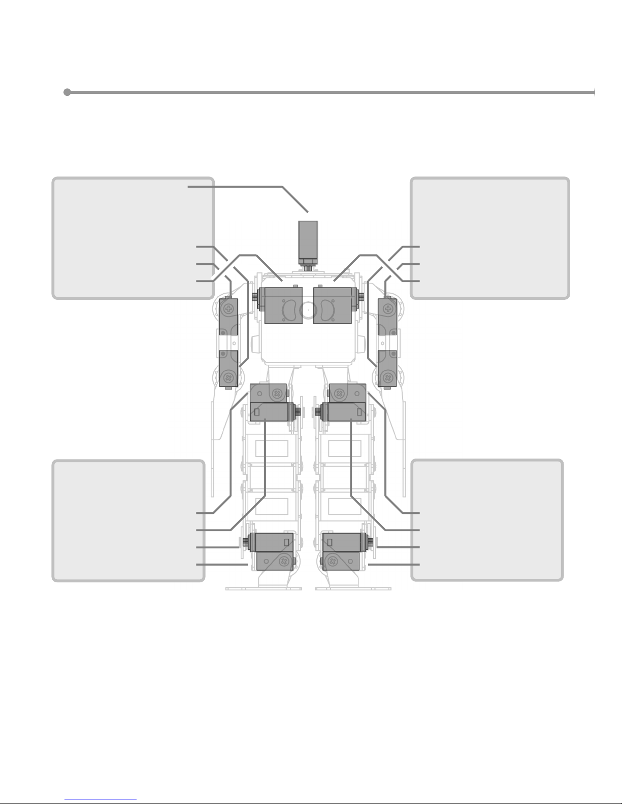
Naming and positioning of the servo motors
S6:Head
S5:(Right Eye LED)
S4:(Right Hand)
S3:Right Elbow Roll Axis
S2:Right Shoulder Roll Axis
S1:Right Shoulder Pitch Axis
CN3 CN4
S6:(Right Leg Yaw Axis)
S5:
S4:Right Thigh Roll Axis
S3:Right Thigh Pitch Axis
S2:Right Ankle Pitch Axis
S1:Right Ankle Roll Axis
CN1
S6:(Left Leg Yaw Axis)
S5:
S4:Left Thigh Roll Axis
S3:Left Thigh Pitch Axis
S2:Left Ankle Pitch Axis
S1:Left Ankle Roll Axis
CN2
S6:Power Cable
S5:(Left Eye LED)
S4:(Left Hand)
S3:Left Elbow Roll Axis
S2:Left Shoulder Roll Axis
S1:Left Shoulder Pitch Axis
Page 14
13
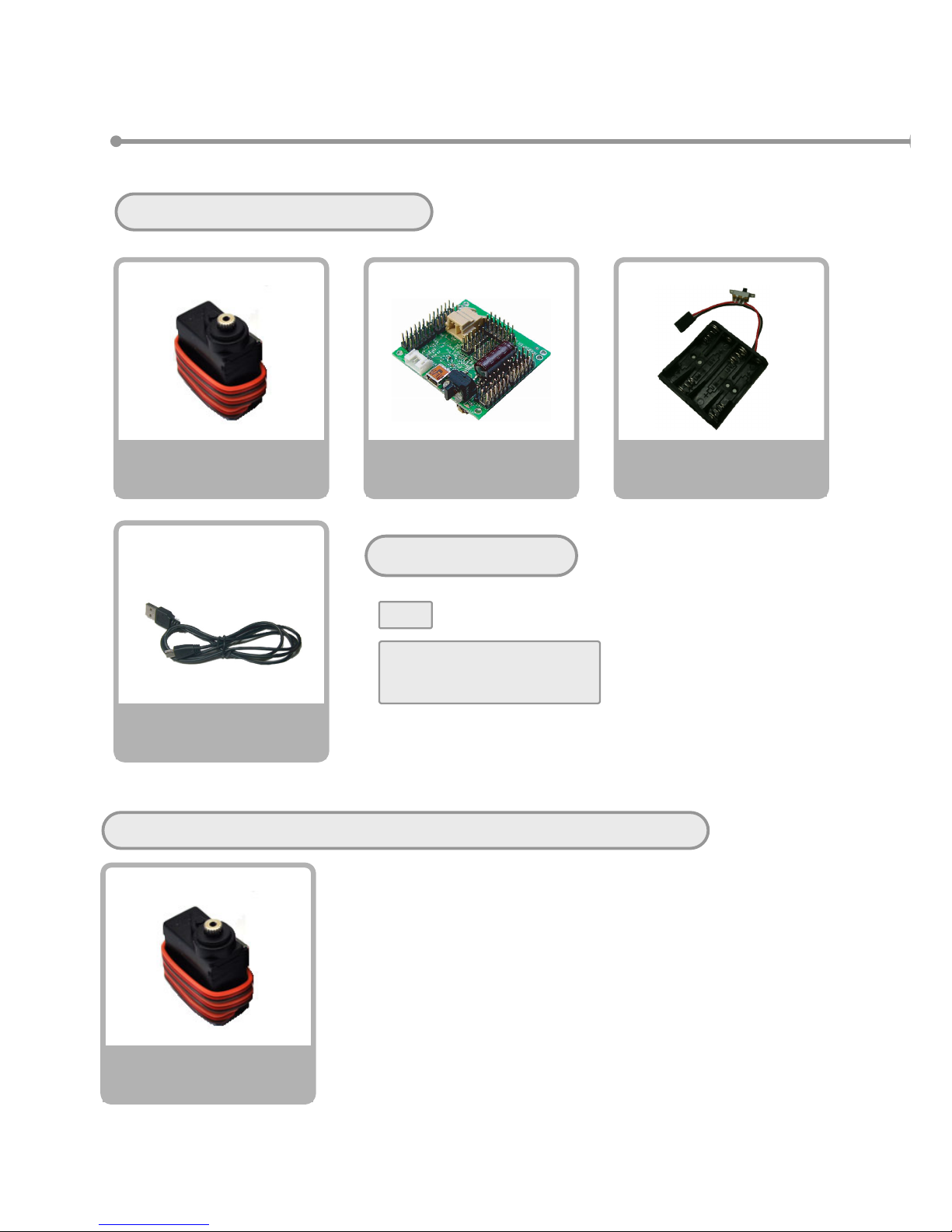
① Setting up servo motors
Please prepare the necessary parts
USB
Cable
×1
CPU Board
VS-RC003HV
×1
Battery Box
×1
Servo motor
VS-S020
×15
If you are installing Yaw axis extension kit, please prepare following parts.
Servo Motor
VS-S020
×2
Other Parts
PC
NiCad rechargeable battery
(AAA、full charged)
Page 15
14
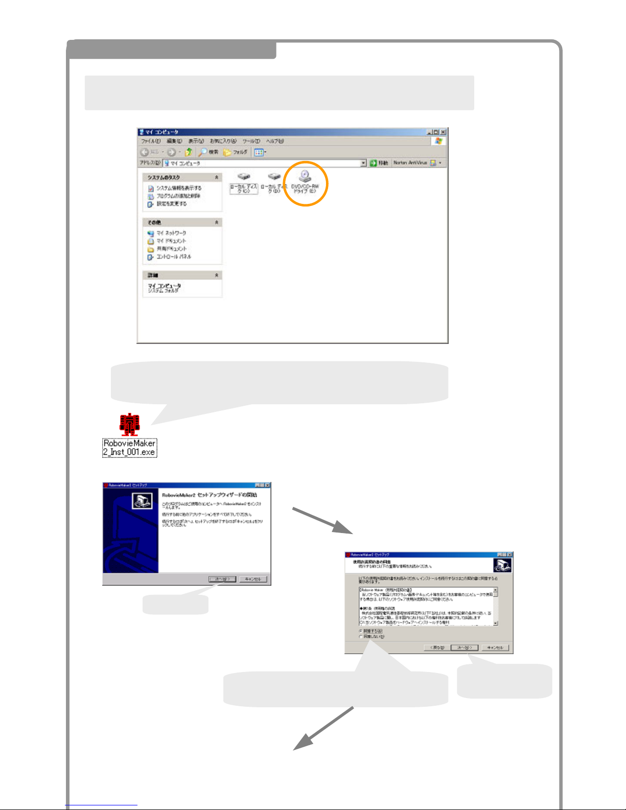
Please insert RobovieMaker2 Install CD into CD drive of your PC, and open the folder
from MyComputer.
Read the license agreement and select
“Agree”.
Click
Next
Please Double click the file called “RobovieMaker2_Inst_***.exe”
(*** indicates the software version)
Click Next
1 Installing RobovieMaker2
Page 16
15
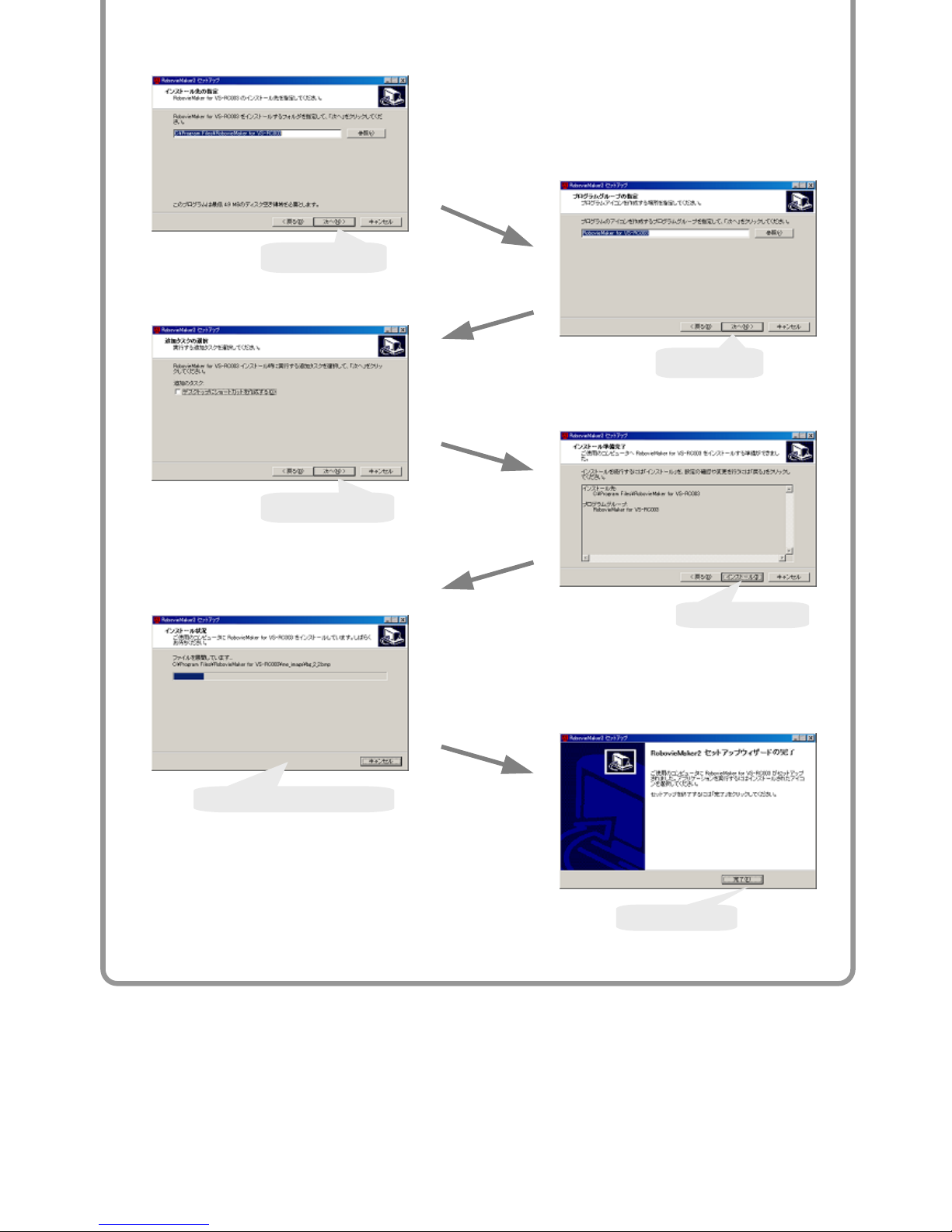
Click Next
Click Next
Click Next
Click Install
It takes a few minutes
Click Finish
Page 17
16
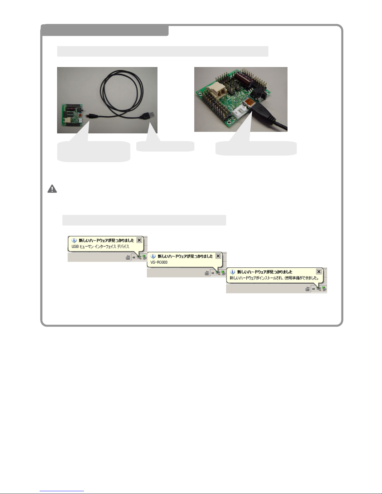
Connect USB cable to
CPU Board.
Connect to PC
Insert the cable firmly.
Connect CPU Board to PC and PC will recognize the CPU Board.
PC will automatically detect the CPU Board when it is connected.
It may take several times to detect the CPU board when you are connecting it for the first time.
Please wait until PC detects the CPU Board.
2 Connect CPU board to PC
Page 18
17
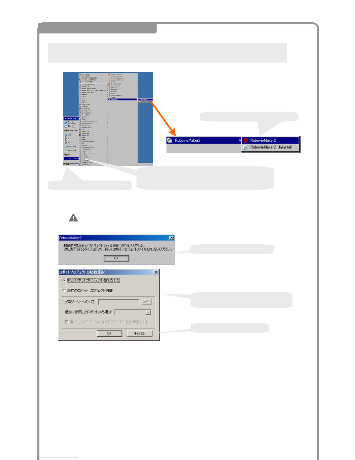
① Click Start
③Click 「RobovieMaker2」
②Place the cursor over the “All Programs”.
The following dialogues will appear when you start the program for the first time.
Click 「 OK 」
Select create new project.
Click 「 OK 」
Start RobovieMaker and prepare for controlling Robot from PC.
5 Creating new robot project
Page 19
18
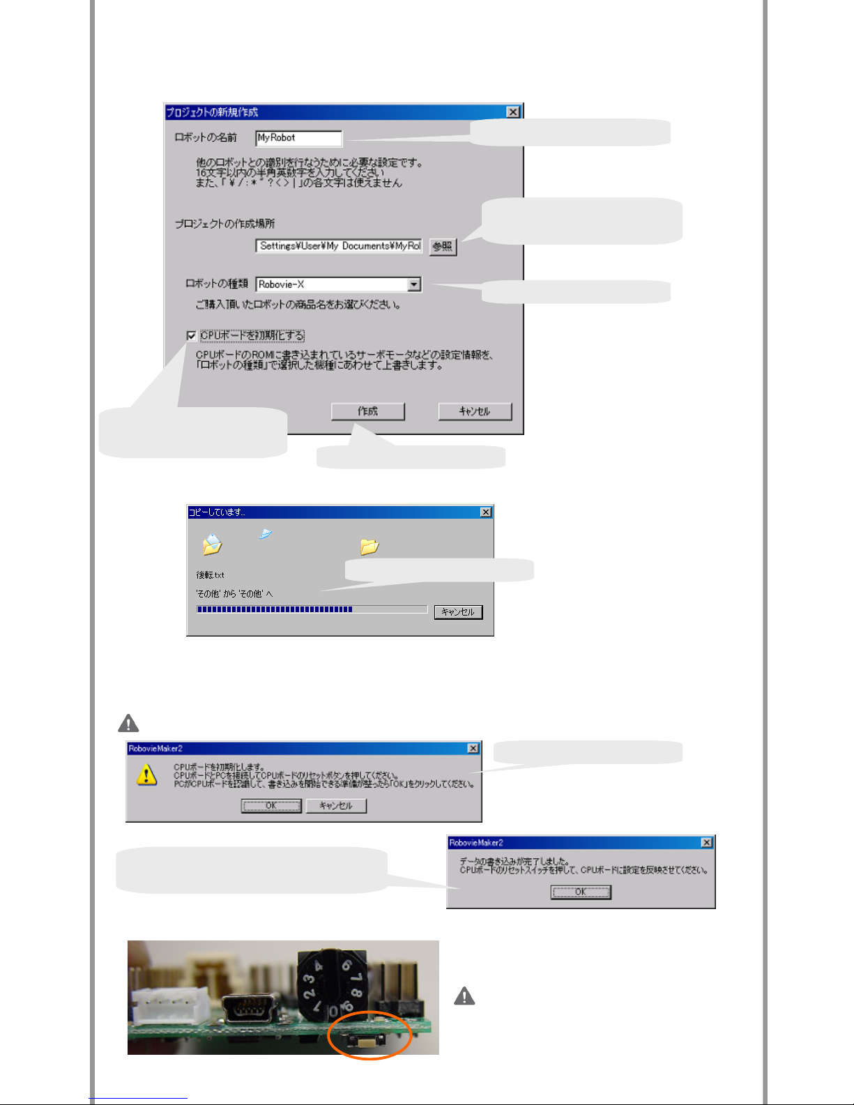
Make sure you select this
check box.
Type in name of your robot.
Select directory your want to
save the data of the robot.
Select “Robovie-nano”
Click “Create”
Push the reset button on the CPU
Board and click “OK”.
Click OK
Click “OK”
Please initialize your CPU Board if you are using new board.
Make sure you press the reset button before you
click the “OK” button.
Page 20
19
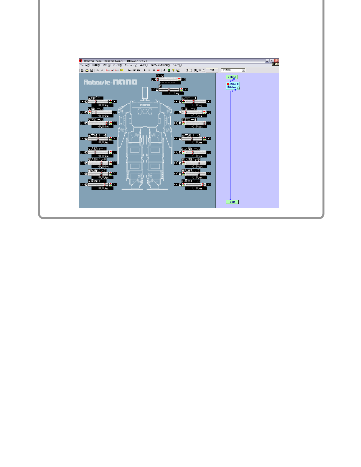
The initialization of the CPU Board is completed.
It will open the following window.
Page 21
20
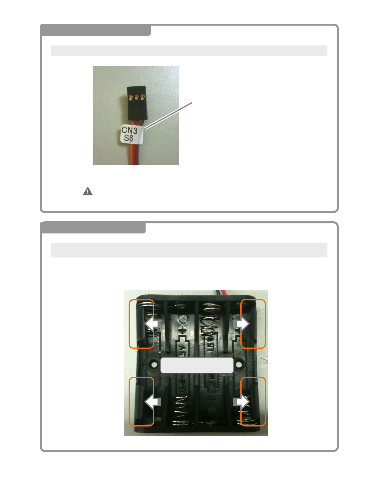
3 Numbering Servo Motors
Placing number tags on to the cable of each servo motor.
Please use CN1-S6 and CN2-S6 for “Yaw Axis kit”.
If you are installing the Yaw Axis kit, please place the CN1-S16 and CN2-S6 to
the servo cables.
4 Preparing Battery Box
Please push the tabs (circled in orange) outward so that you can insert and takeout the battery easily.
Push outward
Please place the tag onto
the cable, not the connector.
Page 22
21
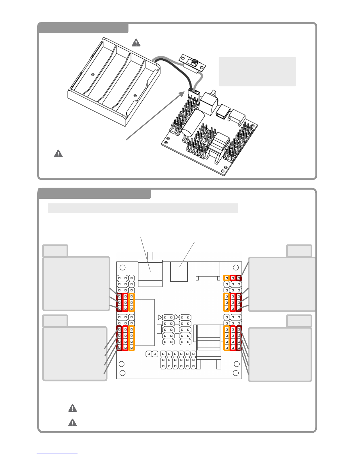
S6:Head
S5:(Right Eye LED)
S4:(Right Hand)
S3:Right Elbow Roll Axis
S2:Right Shoulder Roll Axis
S1:Right Shoulder Pitch Axis
S6:(Right Leg Yaw Axis)
S5:
S4:Right Thigh Roll Axis
S3:Right Thigh Pitch Axis
S2:Right Ankle Pitch Axis
S1:Right Ankle Roll Axis
S6:(Right Leg Yaw Axis)
S5:
S4:Left Thigh Roll Axis
S3:Left Thigh Pitch Axis
S2:Left Ankle Pitch Axis
S1:Left Ankle Roll Axis
S6:Power Cable
S5:(Left Eye LED)
S4:(Left Hand)
S3:Left Elbow Roll Axis
S2:Left Shoulder Roll Axis
S1:Left Shoulder Pitch Axis
Connect the cable on
CN4-6 Pin of the CPU
Board.
Make sure the black (or brown)
cable is placed toward outside.
Connecting all servo motors onto the CPU board.
CN1 CN2
CN4 CN3
茶赤橙 茶赤橙 橙赤茶 橙赤茶
Place the cables so that the brown or black cable goes to outside.
6 Connecting Servo Motors
USBPort
Rotary Switch
Do not insert battery
CN6
CN7
CN11
CN1 CN2
CN4 CN3
CN5
If you connect wires wrong, the robot may not work properly.
5 Connecting Battery Box
Page 23
22
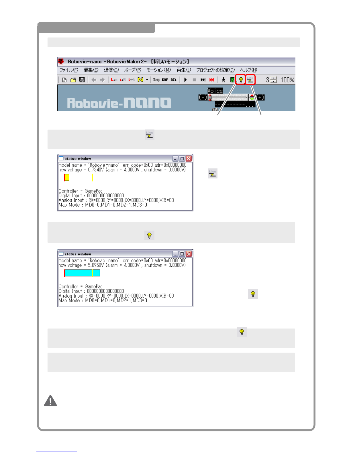
7 Positioning Servo Motors
Start up RobovieMaker2.
Connect CPU Board to PC and push the button in tool bar.
Place batteries in the battery box and turn on the switch, and turn on the switch on the CPU Board.
Then, click servo motor ON/OFF button in tool bar. It will power up the servo motors.
When you turn on the power, it will
change the voltage shown in the
status window.
If you press the button, all the
servo motors moves to cente
r
position.
Button opens status
window.
After verifying that all the servo motors are running, press the ON/OFF button again and turn all
servo motors off.
You have completed steps to find center position of servo motors.
For the farther steps, do your assembly relative to this cente
r
position.
Please do not move the output shaft of the servo motors while
placing servo horns.
Now, follow the above procedure reverse direction, and turn off the switch.
Then, remove the USB cable, battery box, and servo motors from CPU board.
CommunicServo Motor ON/OFF Button
Page 24
23
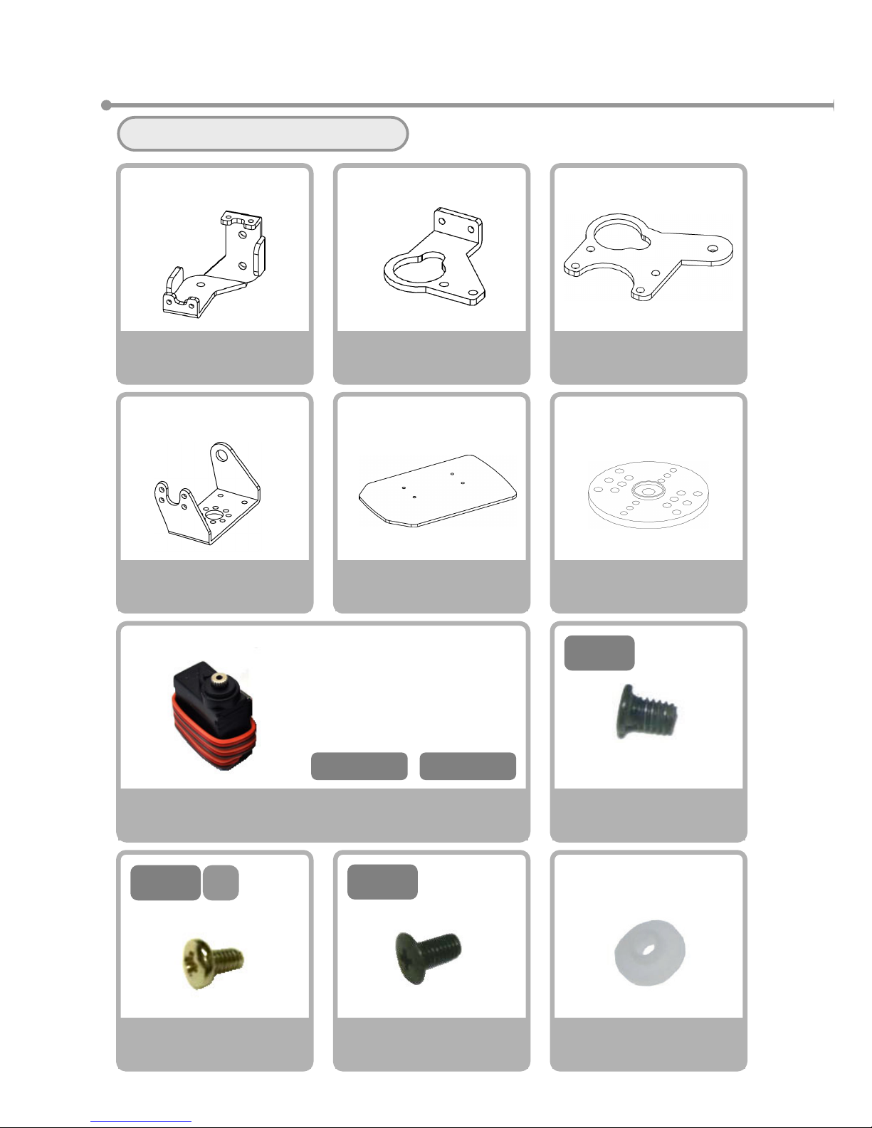
②Right Leg Assembly
Please gather the necessary parts
Servo Motor
VS-S020
×2
VS-S020 Type
Servo Horn
×1
Bushing
×1
Screw NA
M2-3 Course Thread
×10
6
M3-
Screw NE
M3-6 Fine Thread
×1
3
M2-
Servo Holder A (Right)
×1
Servo Holder B (Right)
×1
Servo HolderD
×1
BracketA(Right)
×1
Foot Plate
×1
4
M2-
S
Screw NC
M2-4 S Tight
×5
CN1-S1 CN1-S2
※ Please prepare the servos
with the following seals
attached
。
Page 25
24
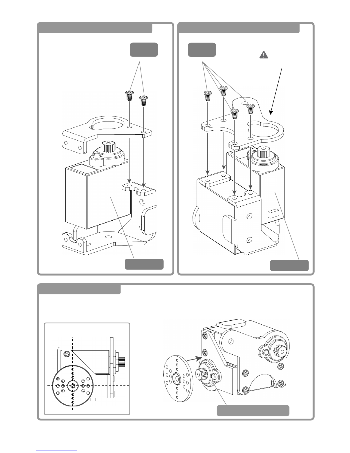
1 Right Ankle Block Assembly ①
3
M2-
2 Right Ankle Block Assembly ②
3 Back of Right Leg ①
3
M2-
Watch the
Direction
Servo Horn Positioning
CN1-S1
CN1-S2
CN1-S1Installed
Page 26
25
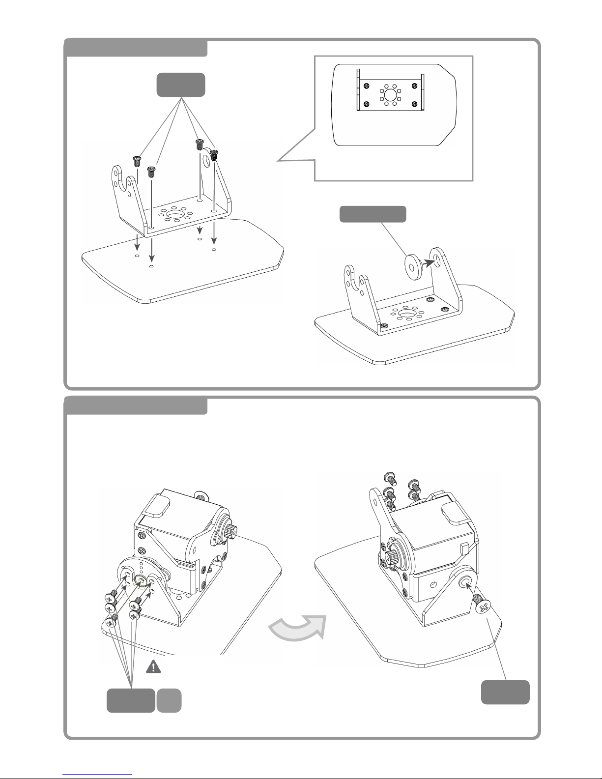
4 Back of Right Leg ②
3
M2-
5 Back of Right Leg ③
4
M2-
S
6
M3-
Bushin
g
ブ
Inversion
<Back> <Front>
From Above
Note that the screws are too close
Page 27
26
Screw NA
M2-3 Course Thread
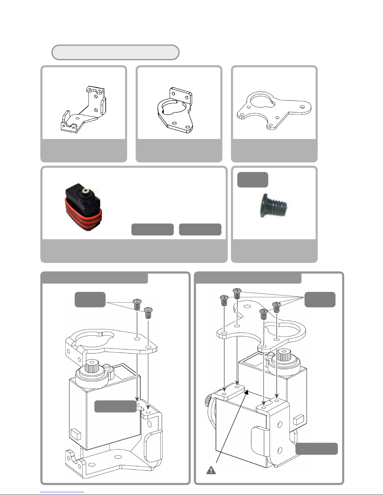
Please gather the necessary parts。
Servo Motor
VS-S020
×2
Screw NA
M2-3 Course Thread
×6
Servo Holder A (Right)
×1
Servo Holder C (Right)
×1
Servo Holder D
×1
3
M2-
CN1-S3 CN1-S4
※Please prepare the servos
with the following seals
attached
。
6 Right Thigh Assembly ① 7 Right Thigh Assembly ②
Do NOT Pinch the Cables!
3
M2-
3
M2-
CN1-S4
CN1-S3
Page 28
27
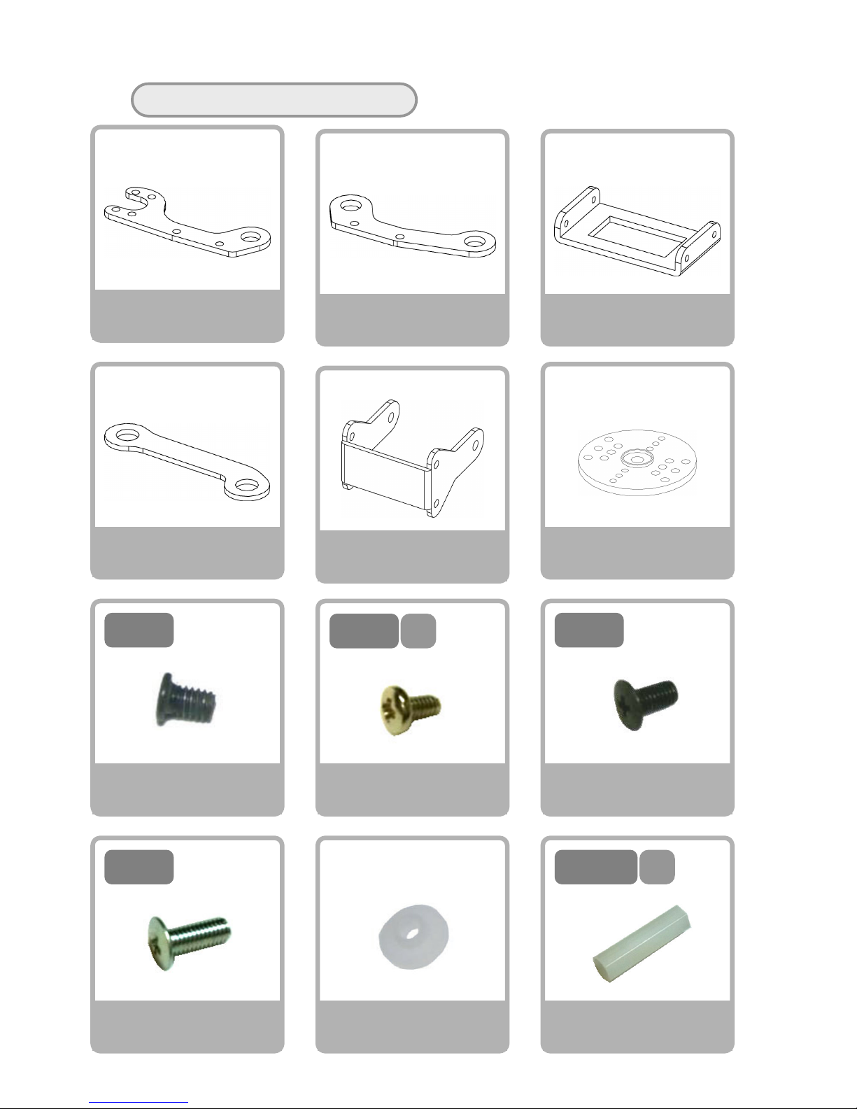
Please gather the necessary parts
Screw NA
M2-3 Course Thread
×8
Link Arm A
×2
Link Arm B
×2
Link Arm C
×2
3
M2-
Rear Link Arm A
×2
Knee Frame A
×1
4
M2-
S
Screw NF
M3-8 Fine Thread
×2
8
M3-
Spacer C
M3-20(Hexagonal)
×1
Screw NC
M2-4 S Tight
×10
Screw NE
M3-6 Fine Thread
×8
ス
20
M3-
V
S-S020Type
Servo Horn
×2
Bushing
×10
6
M3-
Page 29
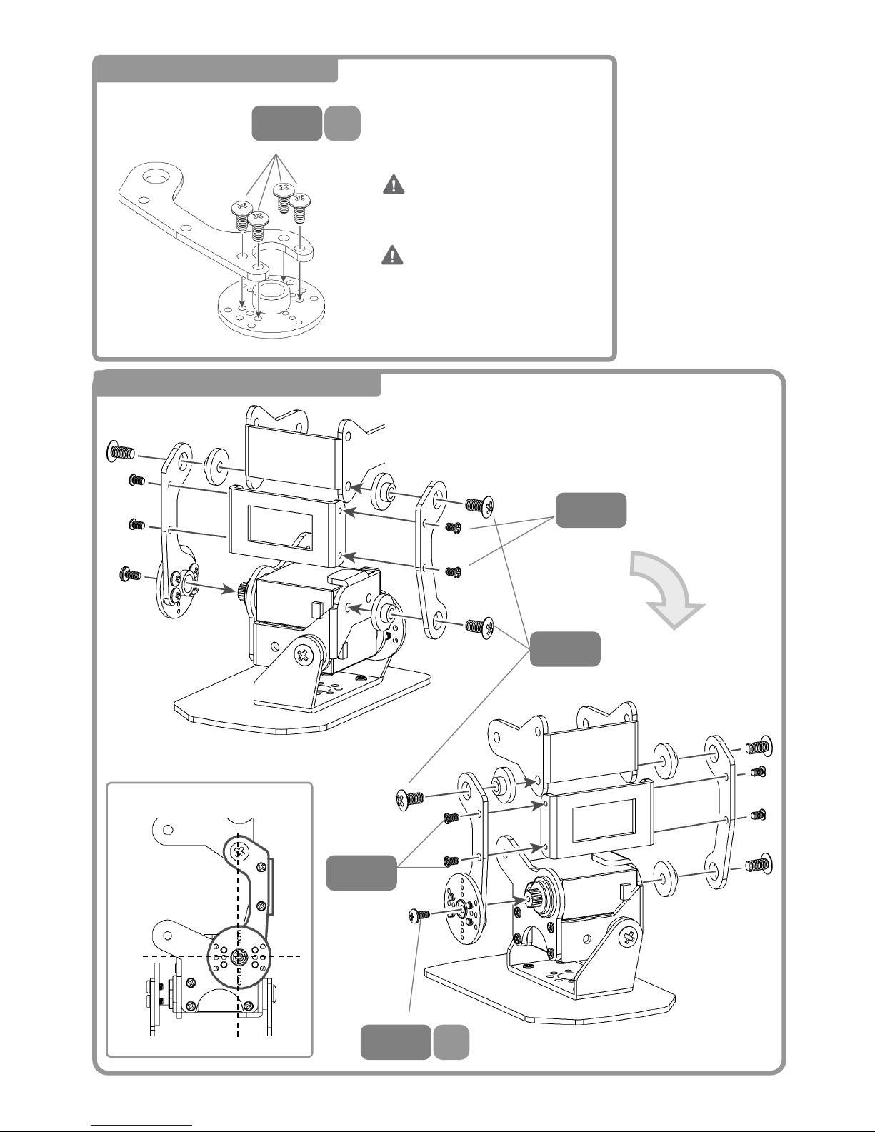
28
8 Right Link Arm Assembly
9 Right Arm Link Assembly ①
4
M2-
S
4
M2-
S
3
M2-
6
M3-
3
M2-
Inversion
Servo Horn Positioning
2 Sets
<Front>
DO NOT Strip the Screw
Threads!
Page 30
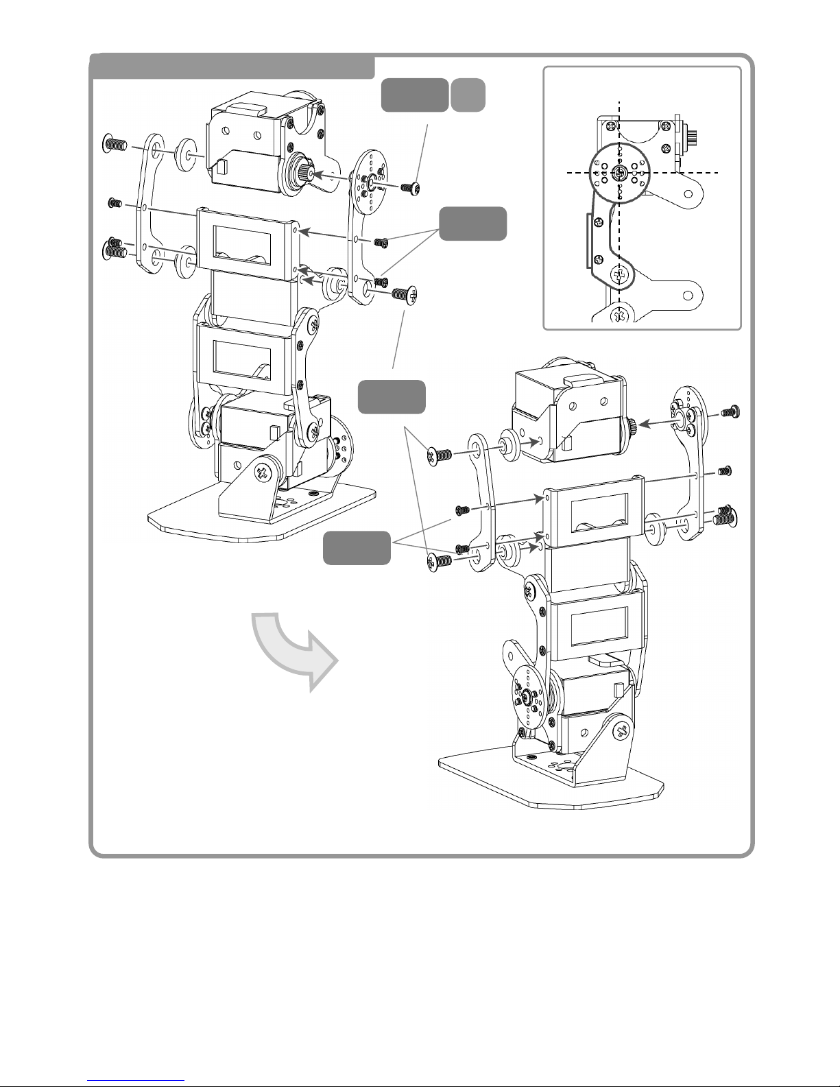
29
10 Right Link Arm Assembly ②
4
M2-
S
3
M2-
3
M2-
6
M3-
Inversion
Servo Horn Positioning
<Front>
Page 31
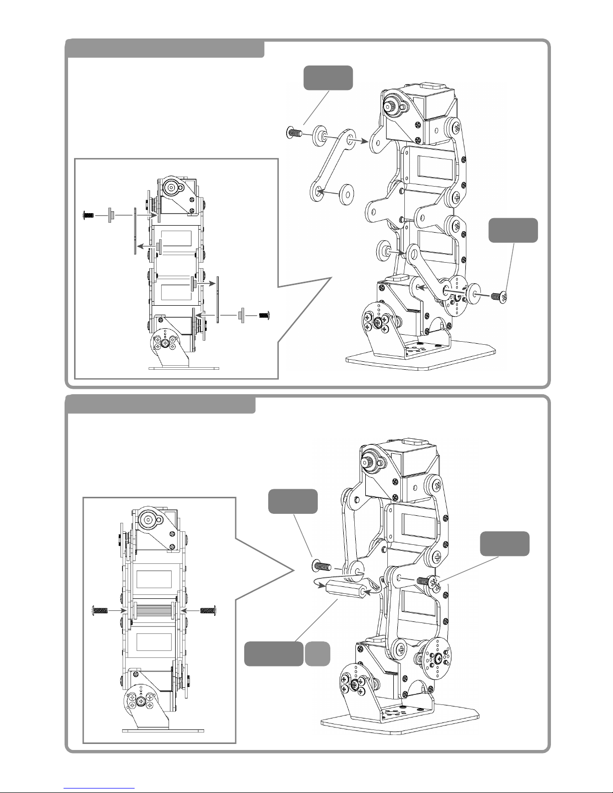
30
11 Attaching the rear link ①
6
M3-
6
M3-
8
M3-
8
M3-
12 Attaching the rear link ②
<Back>
<Back>
Side View
Side and Rear View
Sp
20
M3-
Page 32
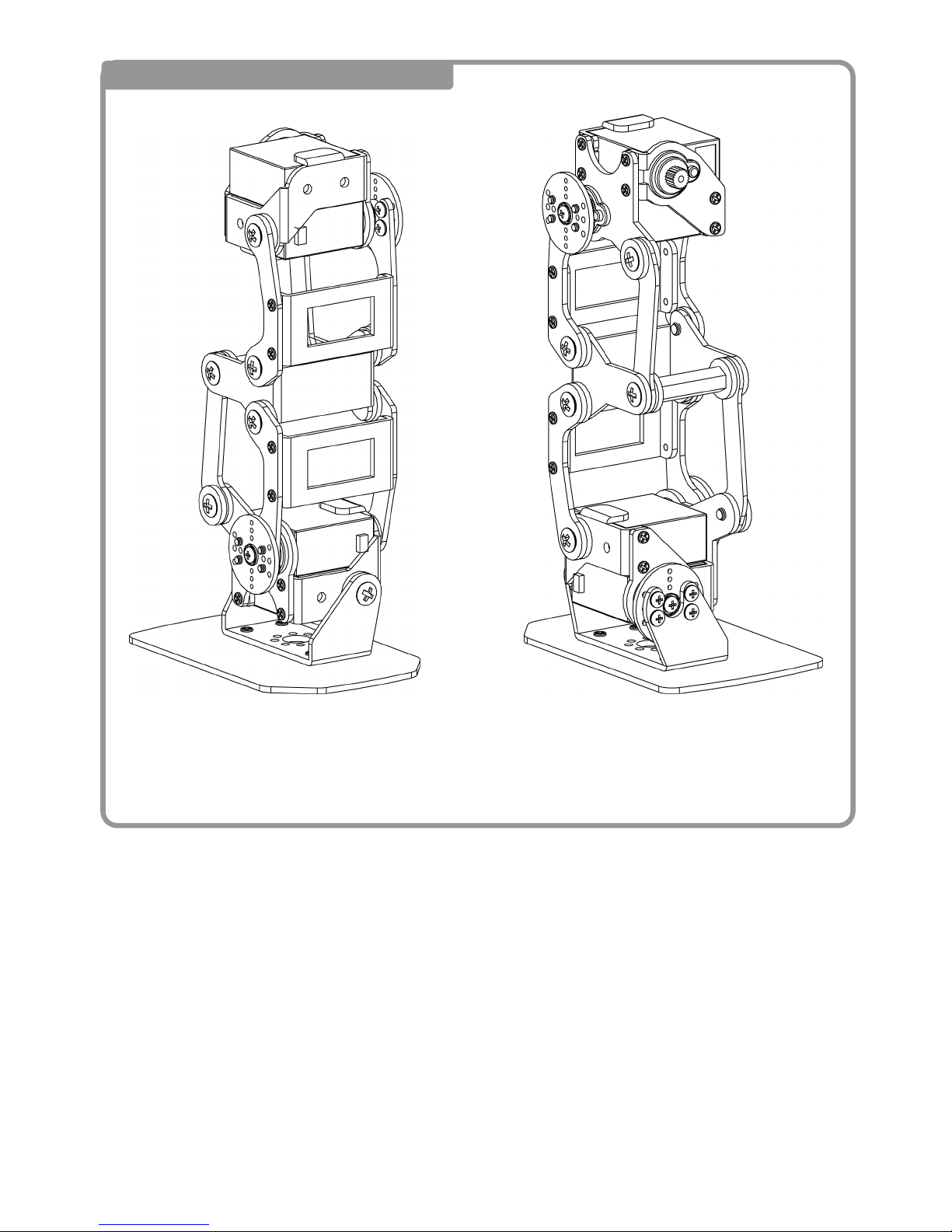
31
13 Completed Right Leg Assembly
<Front> <Back>
Page 33
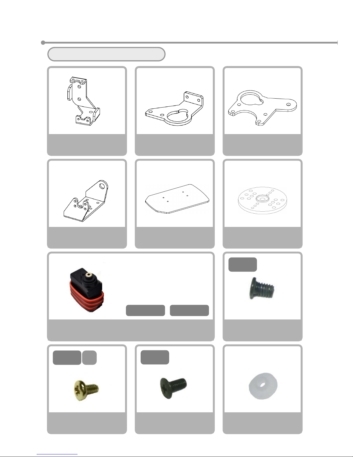
32
③Left Leg Assembly
Please gather the necessary parts
Servo Motor
VS-S020
×2
V
S-S020Type
Servo Horn
×1
Bushing
×1
Screw NA
M2-3 Course Thread
×10
6
M3-
Screw NE
M3-6 Fine Thread
×1
3
M2-
Servo Holder A (Left)
×1
Servo Holder D
×1
Bracket A (Left)
×1
Right Foot Plate
×1
4
M2-
S
Screw NC
M2-4 S Tight
×5
Servo Holder B (Left)
×1
CN2-S1 CN2-S2
※Please prepare the servos
with the following seals
attached
Page 34
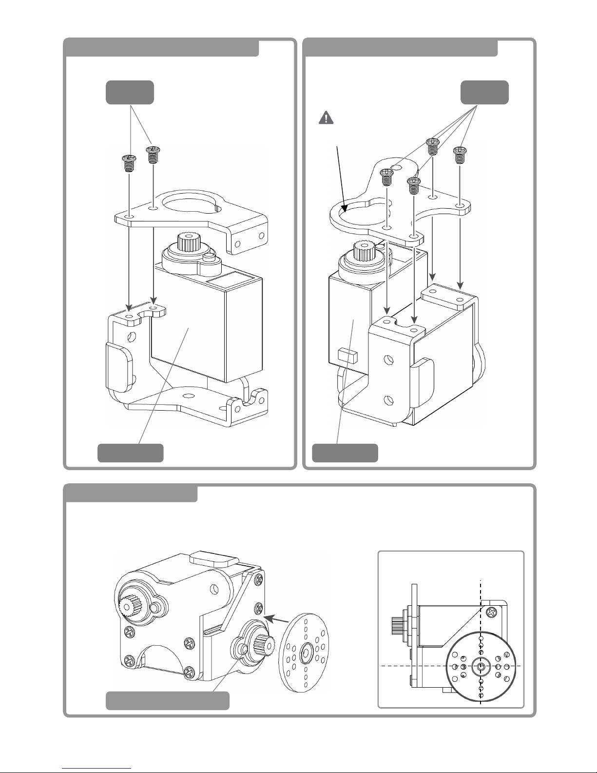
33
1 Left Ankle Block Assembly ①
3
M2-
2 Left Ankle Block Assembly②
3 Back of Left Leg ①
3
M2-
Watch the
Direction
Servo Horn Positioning
CN2-S1 CN2-S2
CN1-S1Installed
Page 35
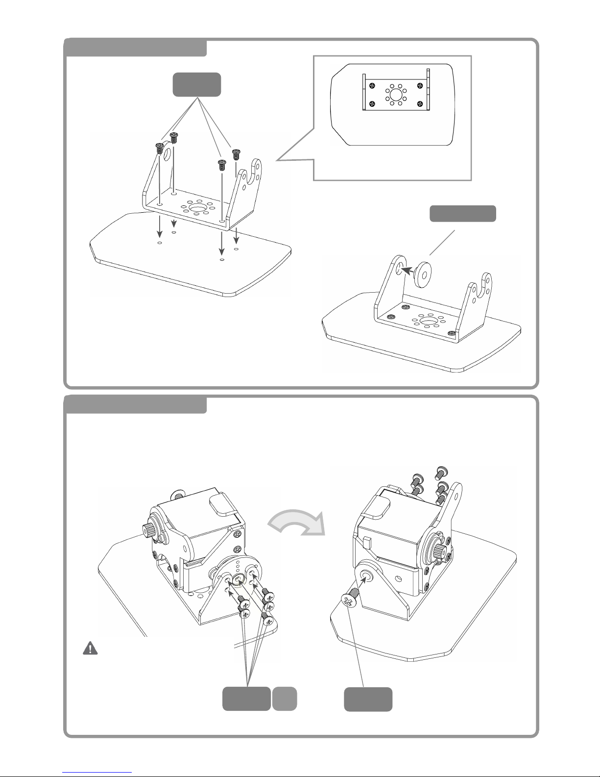
34
4 Back of Left Leg②
3
M2-
5 Back of Left Leg ③
4
M2-
S
6
M3-
Bushin
g
Inverted
<Back> <Front>
Top Down View
Do NOT Strip the Screw
Threads!
Page 36
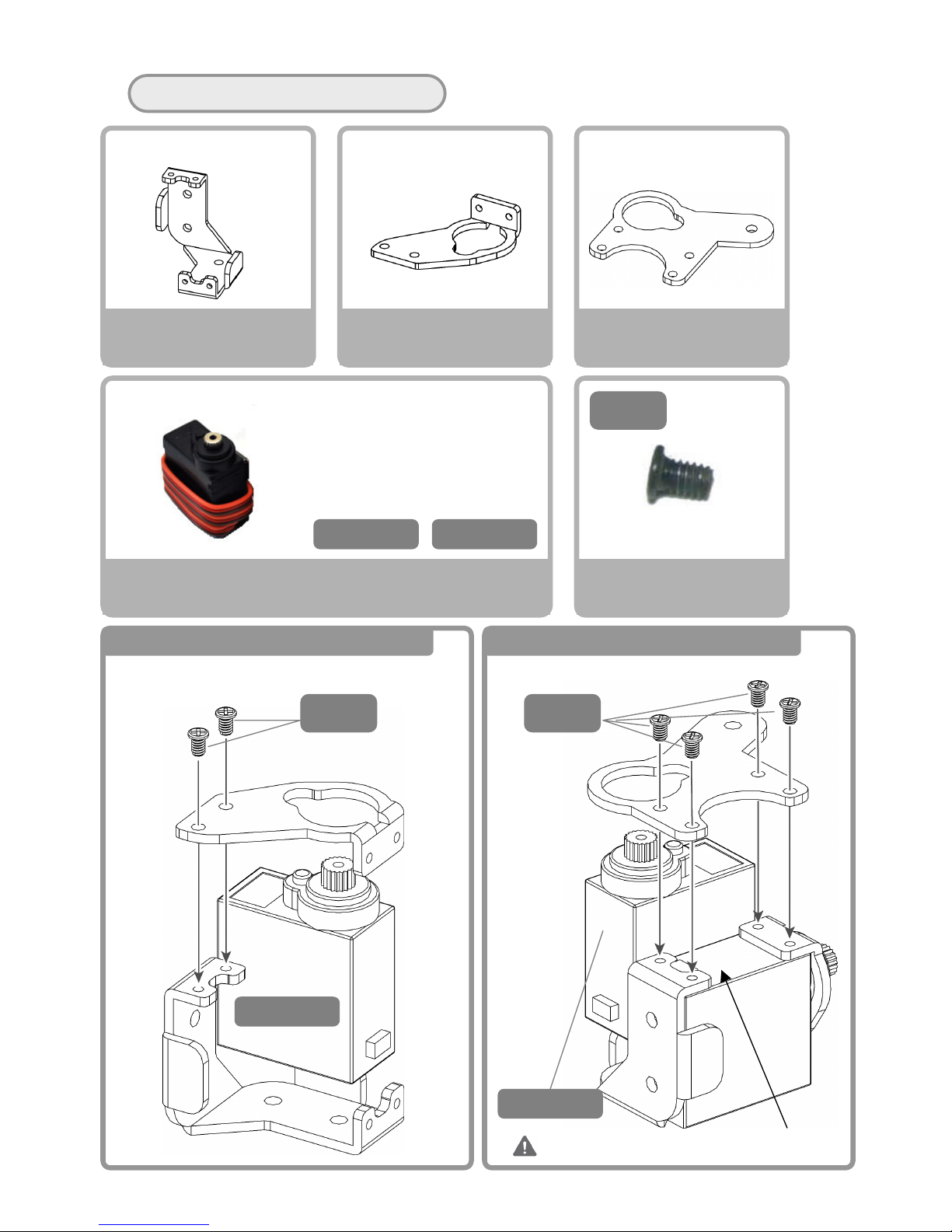
35
Please gather the necessary parts。
Servo Motor
VS-S020
×2
Screw NA
M2-3 Course Thread
×6
Servo Holder A (Left)
×1
Servo Holder C (Left)
×1
Servo Holder D
×1
3
M2-
CN2-S3 CN2-S4
※Please prepare the servos
with the following seals
attached.
6 Left Thigh Block Assembly ① 7 Left Thigh Block Assembly②
DO NOT Pinch the Cables!
3
M2-
3
M2-
CN2-S4
CN2-S3
Page 37
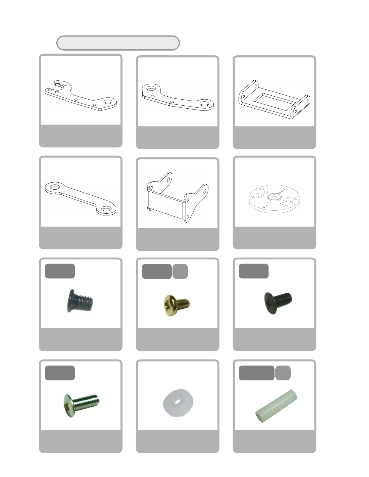
36
Please gather the necessary parts
Screw NA
M2-3 Course Thread
×8
Link Arm A
×2
Link Arm B
×2
Link Arm C
×2
3
M2-
Rear Link Arm A
×2
Knee Frame A
×1
4
M2-
S
Screw NF
M3-8 Fine Thread
×2
8
M3-
Spacer C
M3-20(Hexagonal)
×1
Screw NC
M2-4 S Tight
×10
Screw NE
M3-6 Fine Thread
×8
ス
20
M3-
V
S-S020Type
Servo Horn
×2
Bushing
×10
6
M3-
Page 38
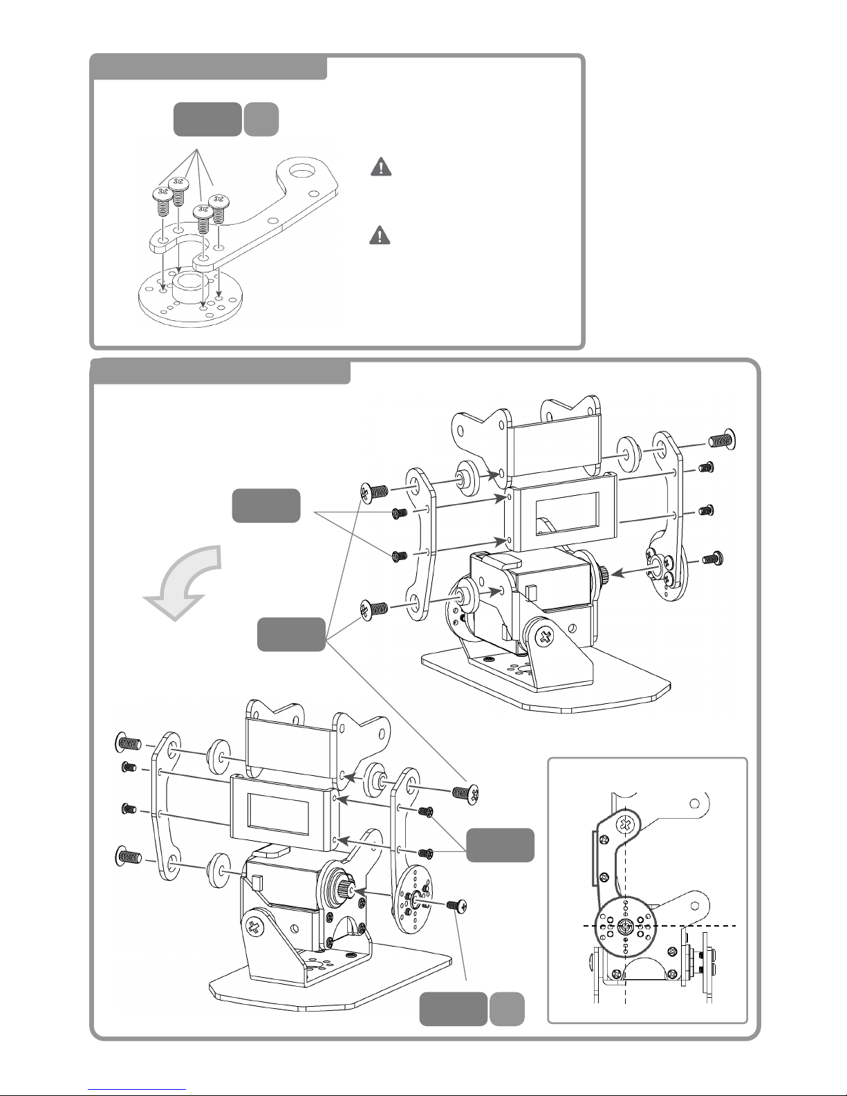
37
8 Left Link Arm Assembly
9 Left Arm Link Assembly ①
4
M2-
S
4
M2-
S
3
M2-
6
M3-
3
M2-
Inverted
Servo Horn Positioning
2 Sets
<Front>
DO NOT Strip the Screw
Threads!
Page 39
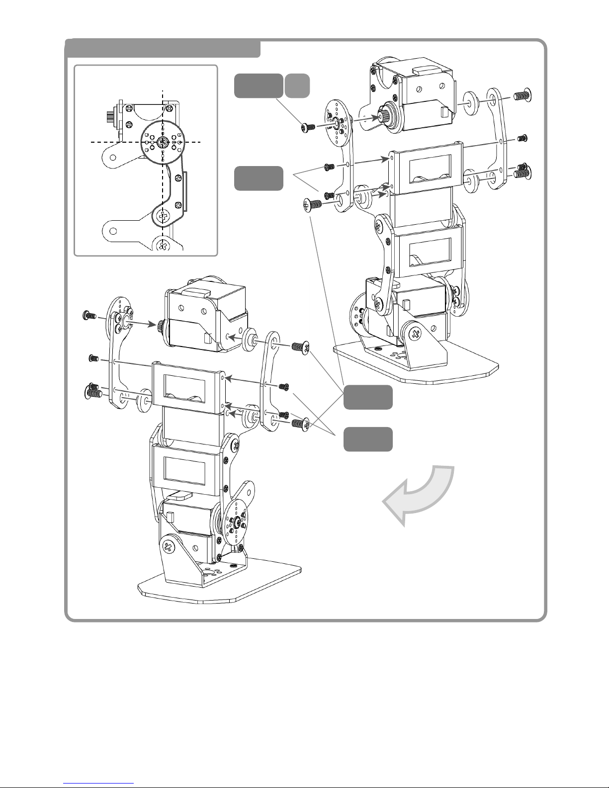
38
10 Left Link Arm Assembly ②
4
M2-
S
3
M2-
3
M2-
6
M3-
Inverted
Servo Horn Positioning
<Front>
Page 40
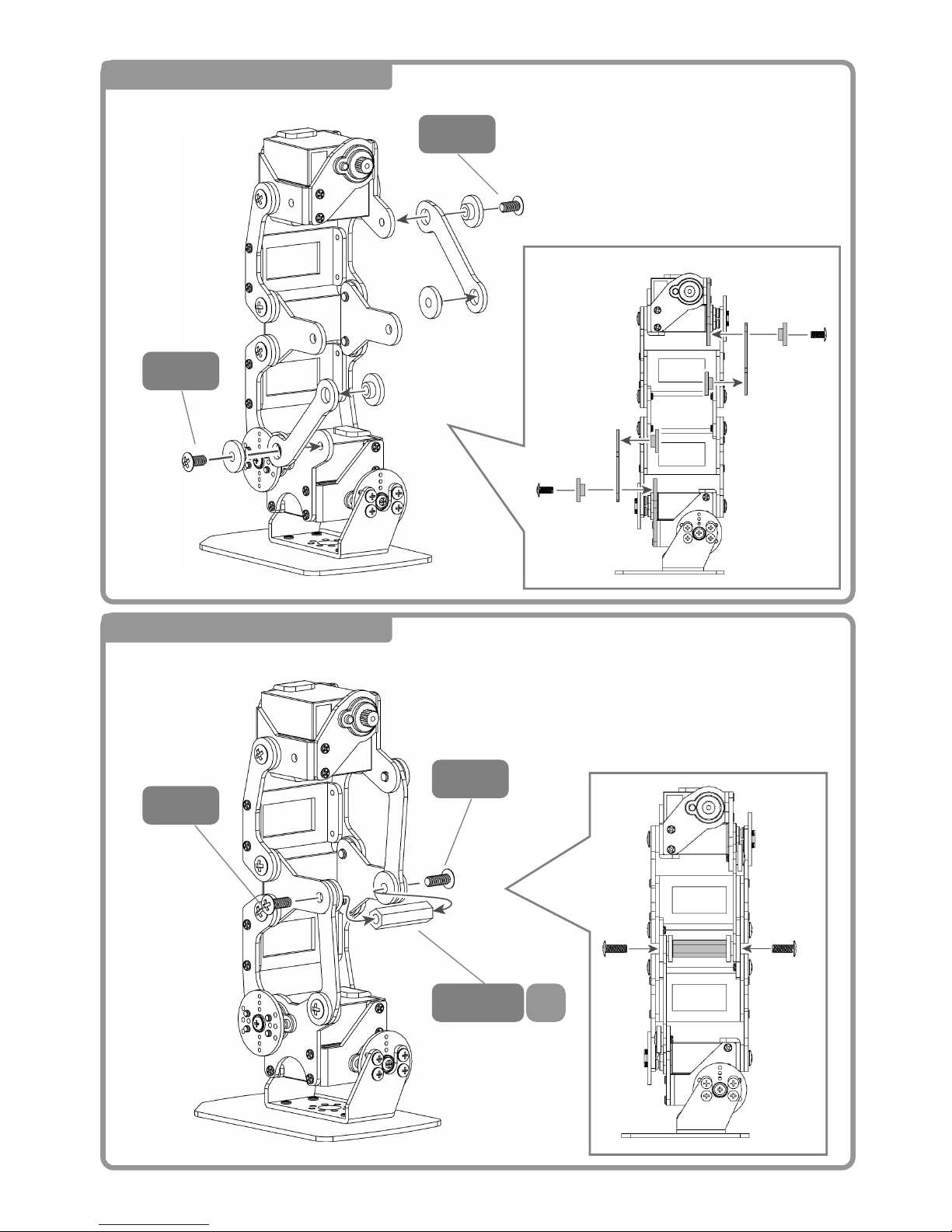
39
11 Attaching the rear link①
6
M3-
6
M3-
8
M3-
8
M3-
12 Attaching the rear link ②
<Back>
<Back>
Side and Rear View
Side View
ス
20
M3-
Page 41
40
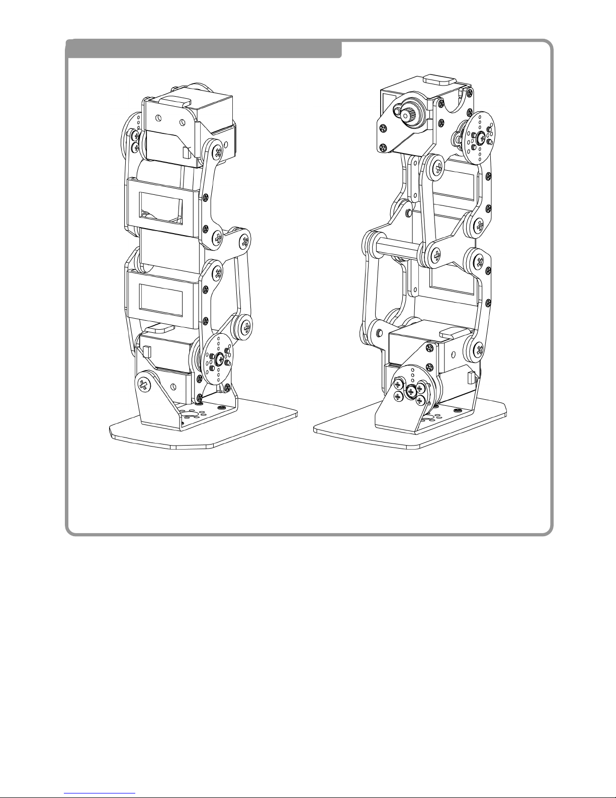
13 Completed Left Leg Assembly
<Front> <Back>
Page 42
41
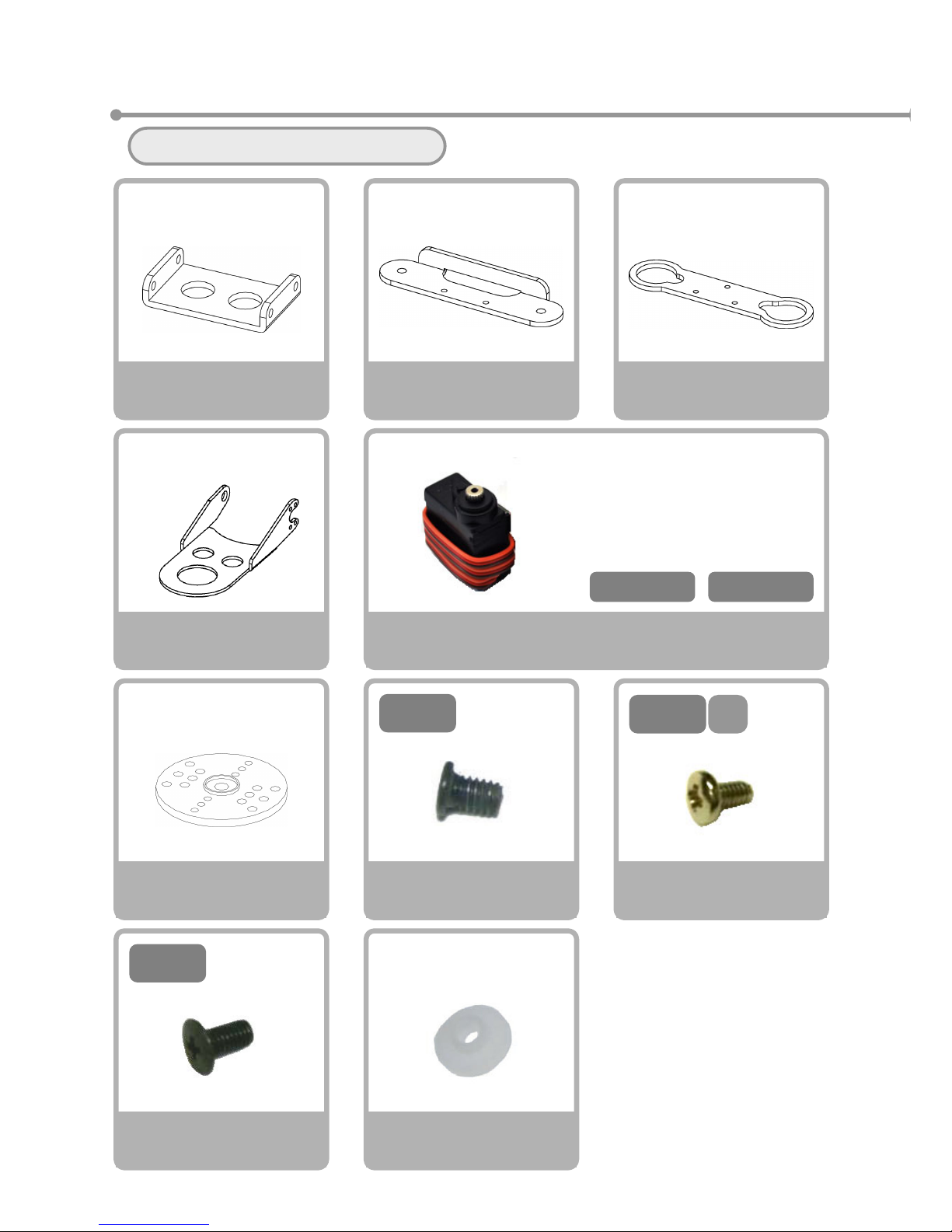
④Right Arm Assembly
Please gather the necessary parts
Servo Motor
VS-S020
×2
V
S-S020Type
Servo Horn
×1
Bushing
×1
Screw N
A
M2-3 Course Thread
×4
6
M3-
Screw NE
M3-6 Fine Thread
×1
3
M2-
Hand Frame (Right)
×1
4
M2-
S
Screw NC
M2-4 S Tight
×5
Holder Arm B
×1
Holder Arm C
×1
Holder Arm A
×1
CN3-S2 CN3-S3
※Please prepare the servos
with the following seals
attached。
Page 43
42
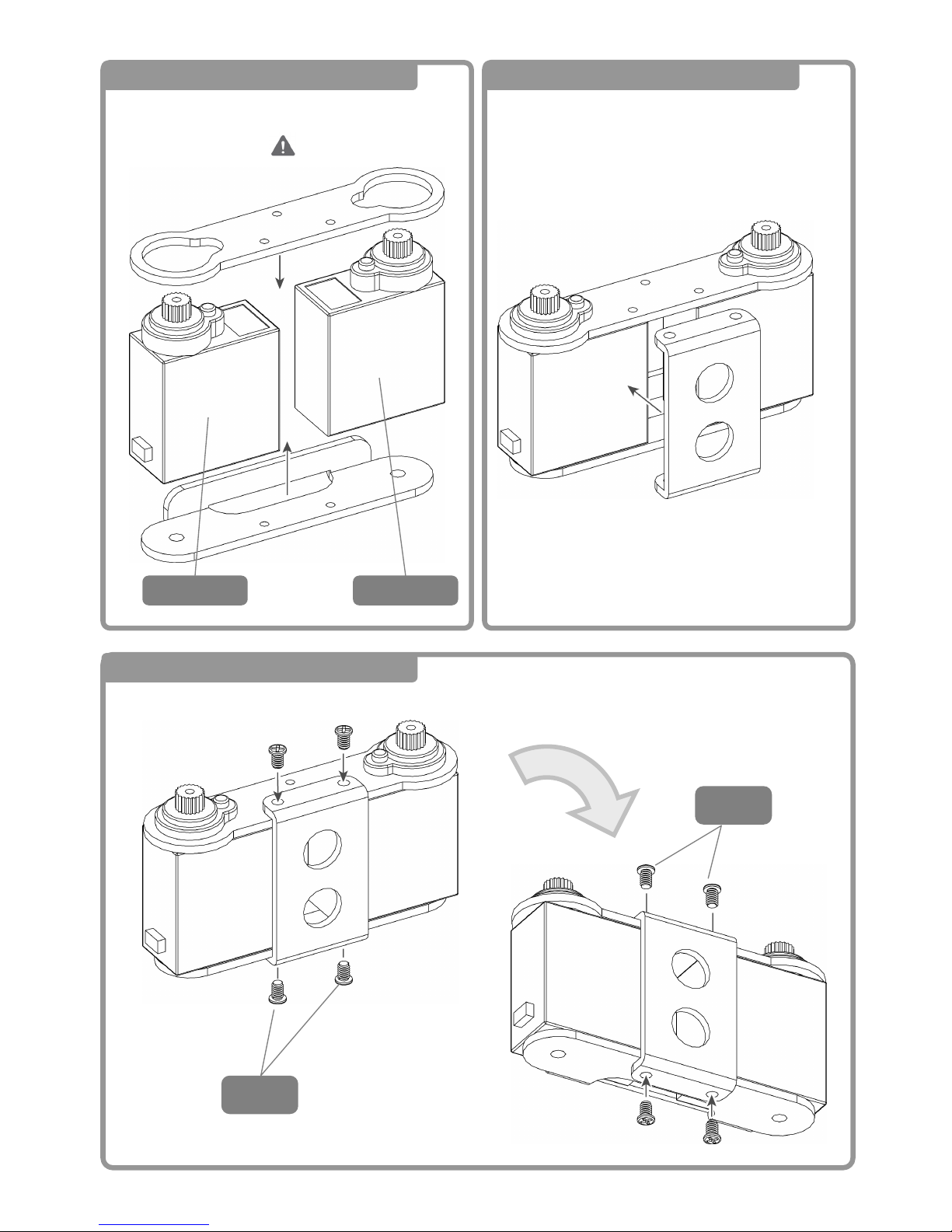
1 Right Arm Block Assembly ①
2 Right Arm Block Assembly ②
3 Right Arm Block Assembly③
3
M2-
Watch the
Direction!
CN3-S2CN3-S3
Inverted
3
M2-
Page 44
43
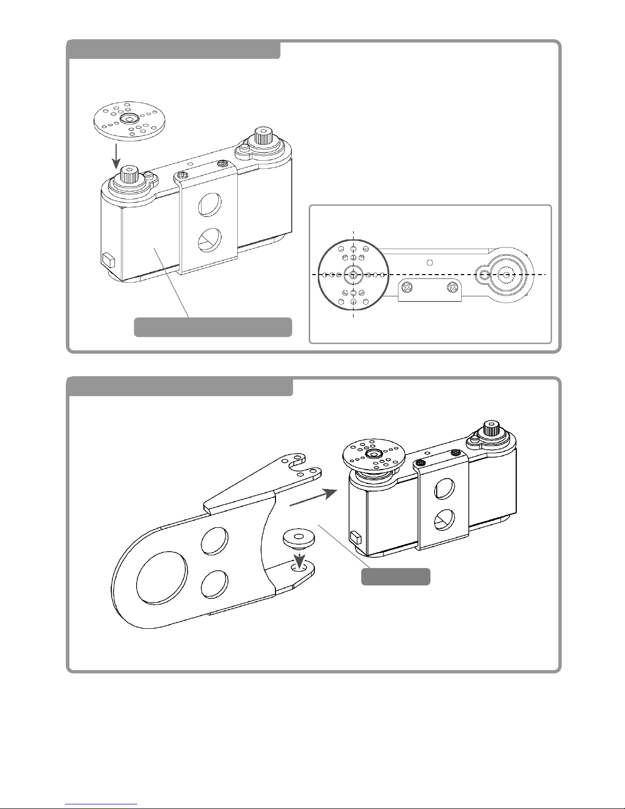
4 Attaching the Right Forearm ①
3
M2-
5 Attaching the Right Forearm ②
Servo Horn Positioning
ブッシュ
Bushin
g
ブ
Attaching the CN3-S3
Page 45
44
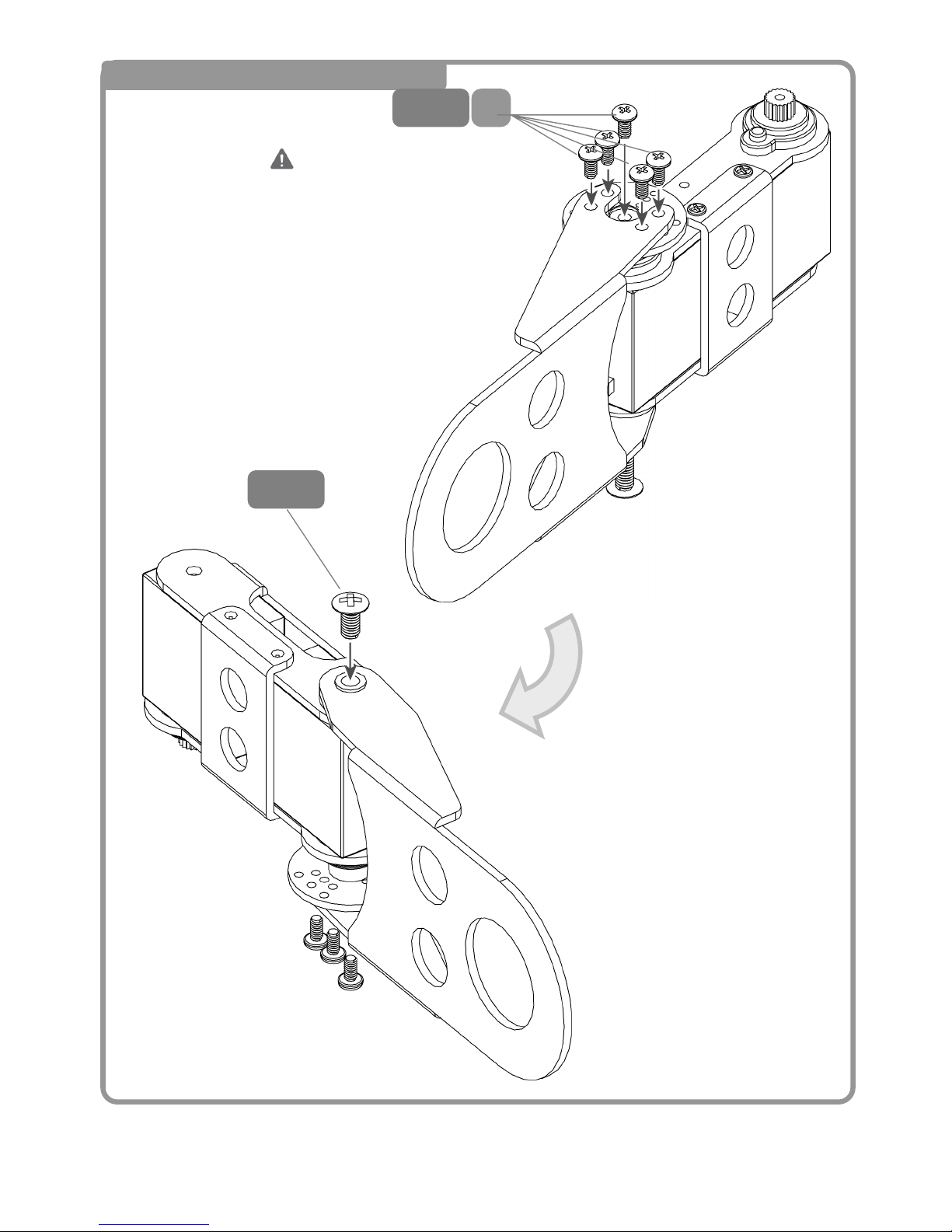
6 Attaching the Right Forearm ③
Inverted
4
M2-
S
6
M3-
<Back>
<Front>
DO NOT Strip the Screw
Threads!
Page 46
45
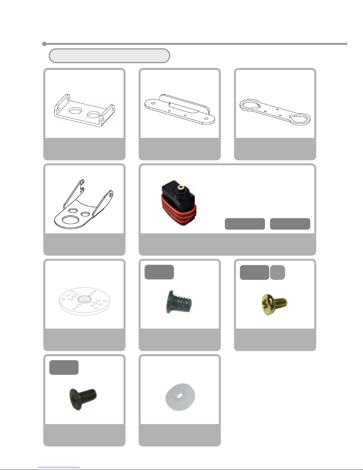
⑤Left Arm Assembly
Please gather the necessary parts
Servo Motor
VS-S020
×2
V
S-S020Type
Servo Horn
×1
Bushing
×1
Screw N
A
M2-3 Course Thread
×4
6
M3-
Screw NE
M3-6 Fine Thread
×1
3
M2-
Hand Frame (Right)
×1
4
M2-
S
Screw NC
M2-4 S Tight
×5
Holder Arm B
×1
Holder Arm C
×1
Holder Arm A
×1
CN4-S2 CN4-S3
※Please prepare the servos
with the following seals
attached。
Page 47
46
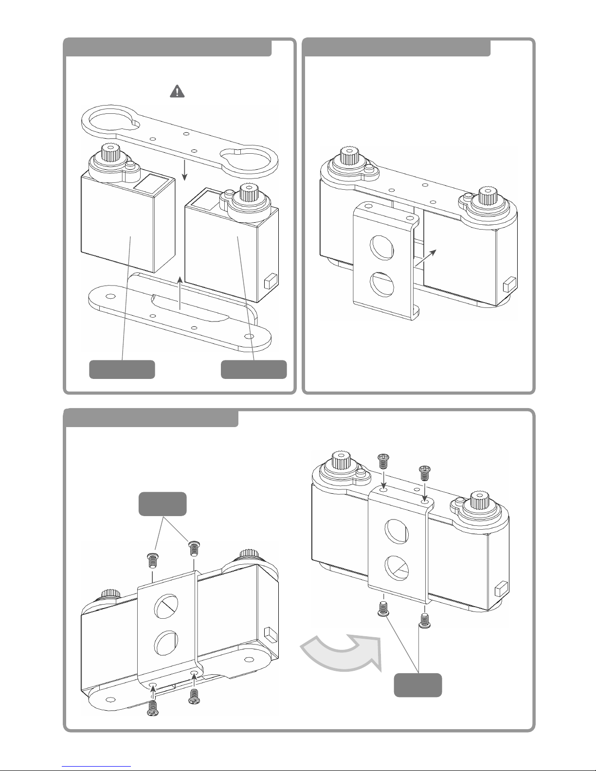
1 Left Arm Block Assembly ①
2 Left Arm Block Assembly ②
3 Left Arm Block Assembly③
3
M2-
向きに注意!
CN4-S3CN4-S2
Inverted
3
M2-
Page 48
47
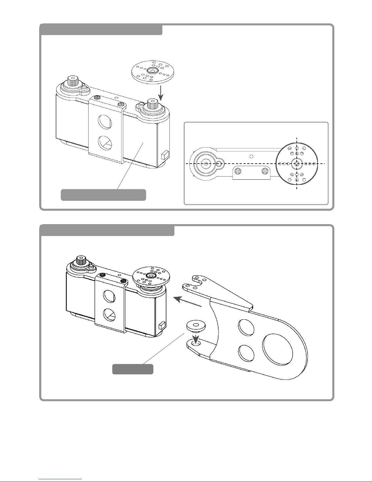
4 Attaching the Right Forearm ①
3
M2-
5 Attaching the Right Forearm ②
Servo Horn Positioning
ブッシュ
Bushin
g
Attaching the CN3-S3
Page 49
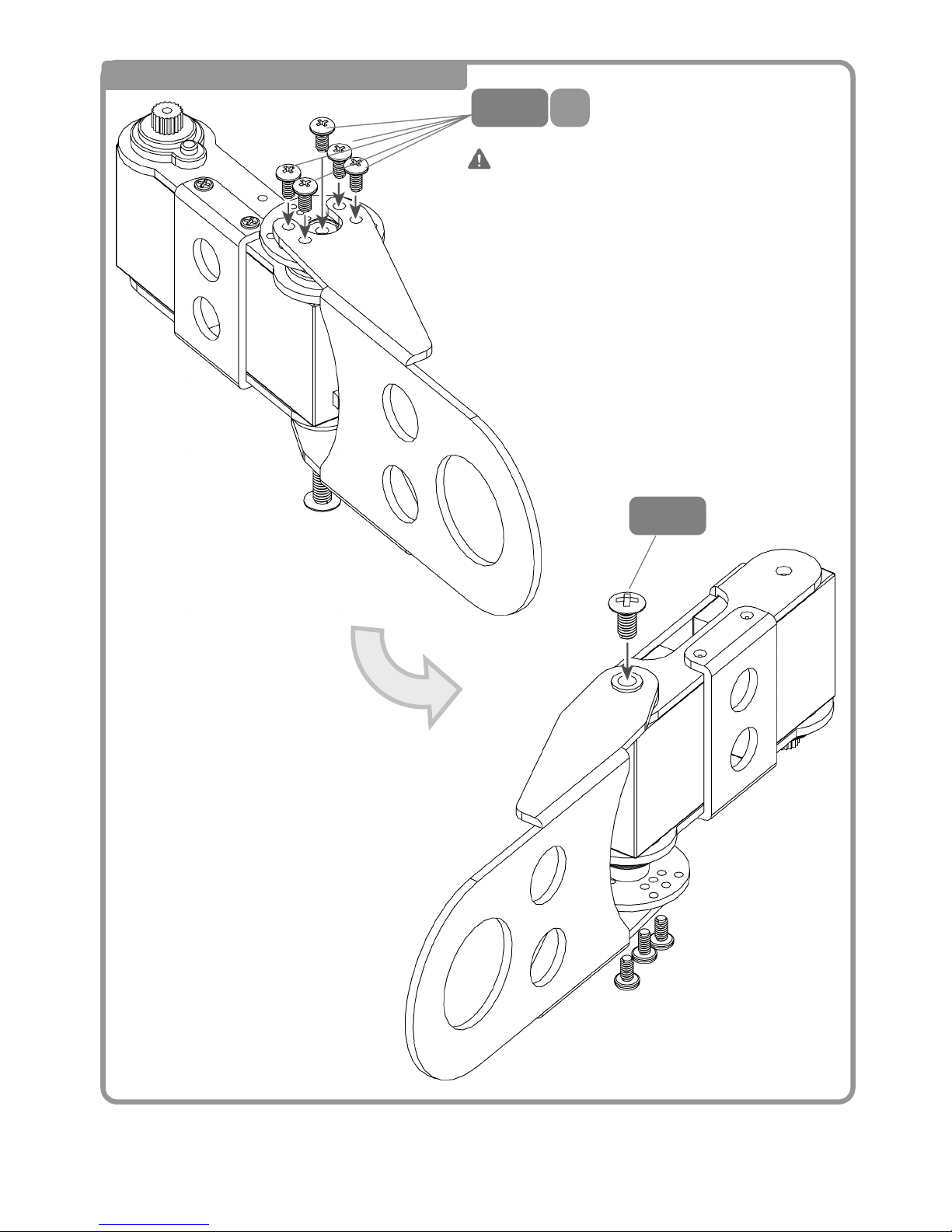
48
6 Attaching the Right Forearm ③
Inverted
4
M2-
S
6
M3-
<Back>
<Front>
DO NOT Strip the Screw
Threads!
Page 50
49
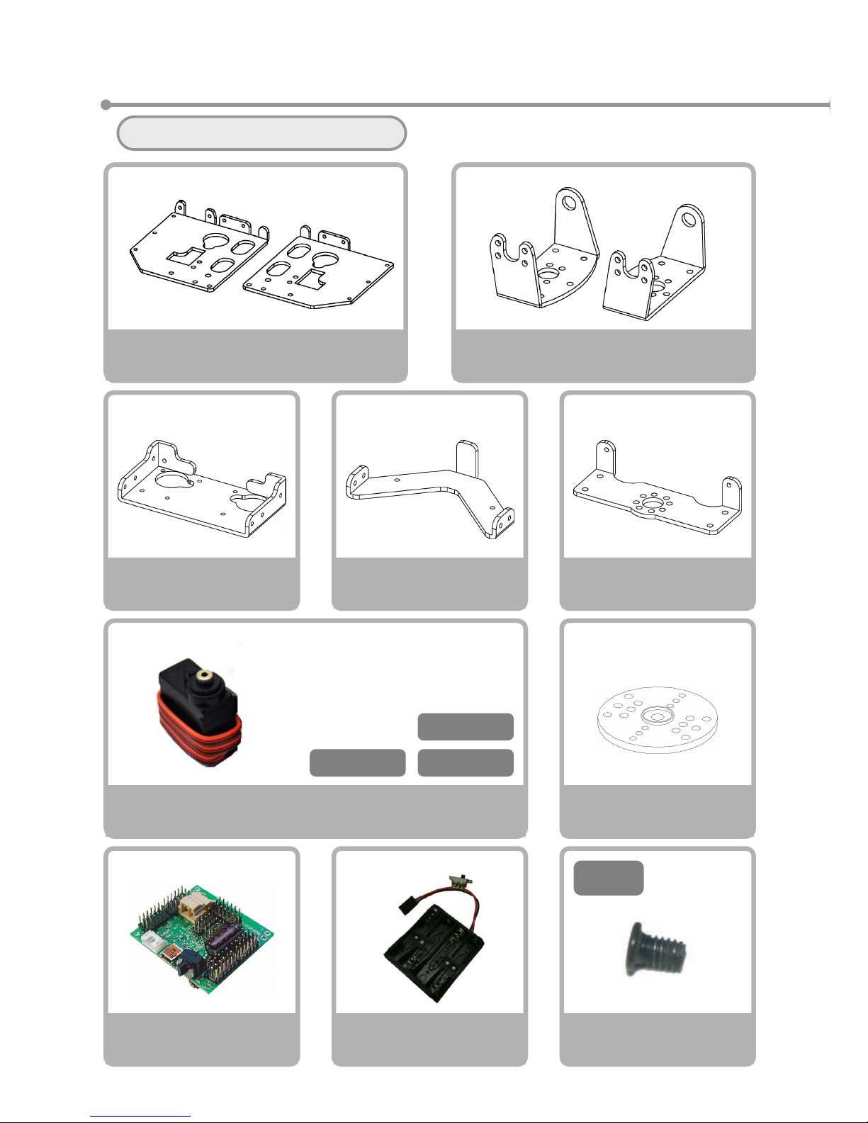
⑥Assembling the Torso
Please gather the necessary items
Servo Motor
VS-S020
×3
V
S-S020Type
Servo Horn
×1
Screw NA
M2-3 Course Thread
×30
3
M2-
Bottom Frame
×1
Bracket B
×1 each
Side Frame
×1 each
Battery Box Frame
×1
Battery Terminal
×1
Top Frame
×1
CN3-S1
CN4-S1 CN3-S6
※Please prepare the servos
with the following seals
attached
CPU Board
VS-RC003HV
×1
Page 51
50
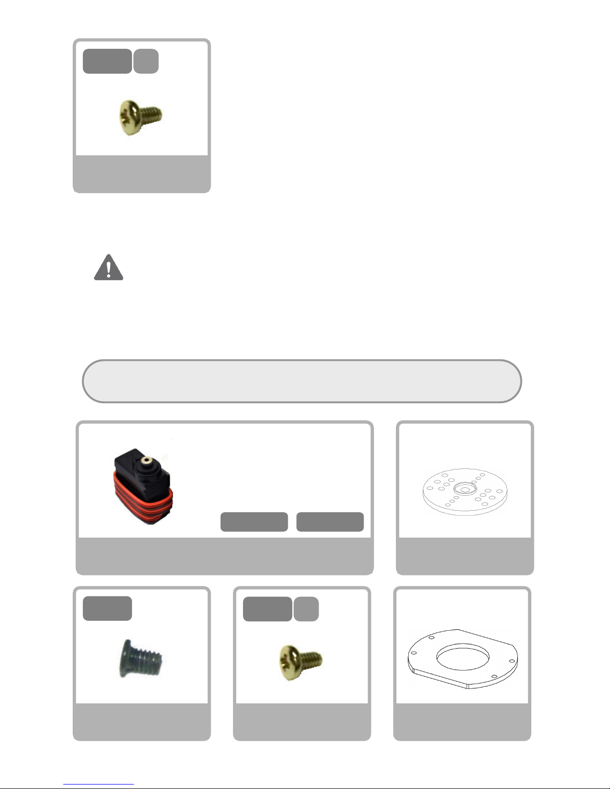
4
M2-
S
Screw NC
M2-4 S Tight
×5
For customers who have purchased the yaw extention set, please
prepare the following parts when assembling at the same time.
Servo Motor
VS-S020
×2
CN1-S6 CN2-S6
※Please prepare the servos
with the following seals
attached
V
S-S020Type
Servo Horn
×2
Screw NA
M2-3 Course Thread
×8
3
M2-
4
M2-
S
Screw NC
M2-4 S Tight
×10
Flat Washer
×2
This page explains the procedures for assembling the yaw axis upgrade with the robot.
If you are assembling the kit without the yaw axis upgrade, please move to the page
and steps listed below.
W/Out Yaw Axis → Start from Page 51 Step 1
W/ Yaw Axis → Start from Page 52 Step 3
Page 52
51
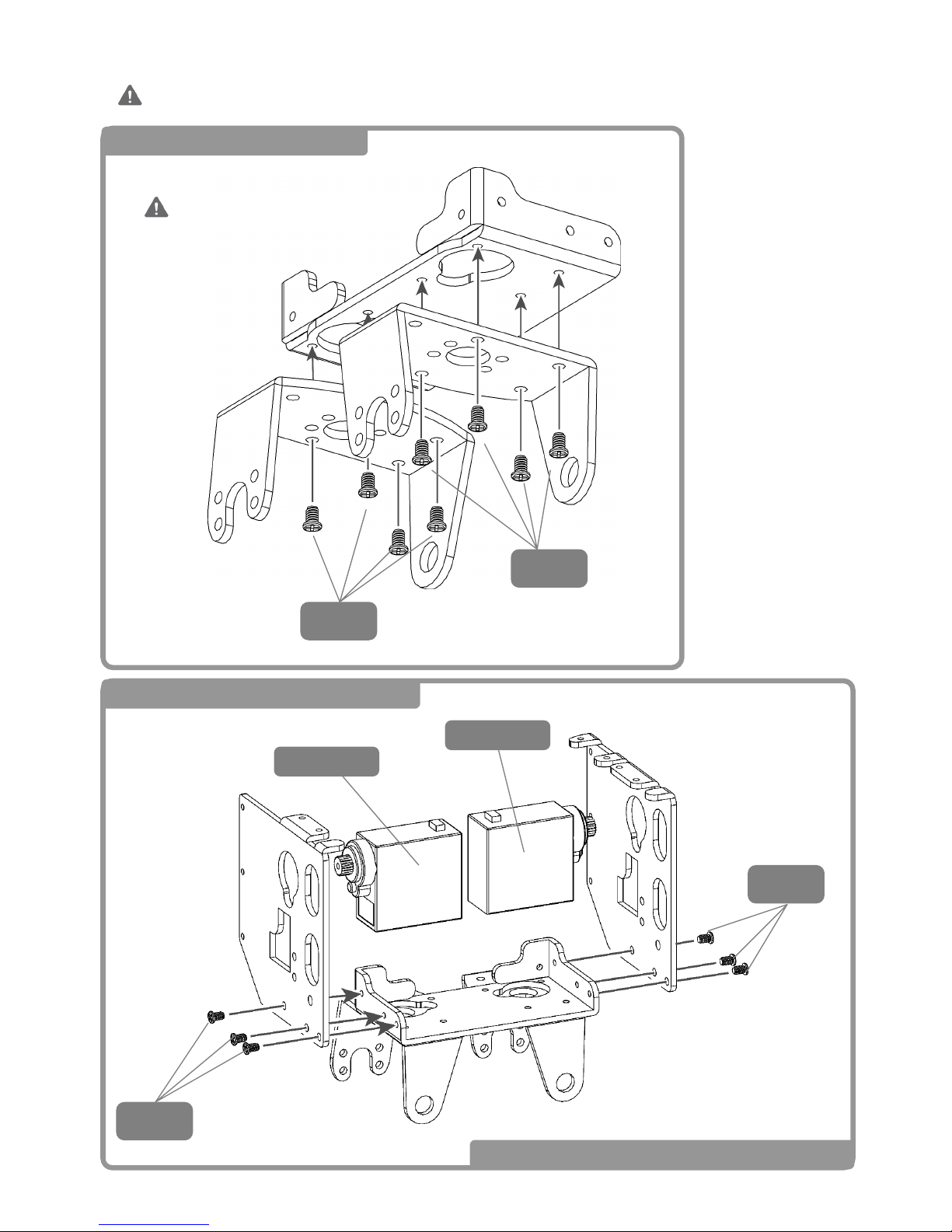
1 Mounting Bracket B
2 Mounting the Arm Pitch Axis
3
M2-
Watch the Direction!
CN3-S1
3
M2-
CN4-S1
3
M2-
3
M2-
Steps 1 and 2 on this page are for robots without the yaw axis extension.
When assembling the yaw axis, please skip to page 52 step 3.
→ 「Move to Step 6: Mounting the Battery Case」
Page 53
52
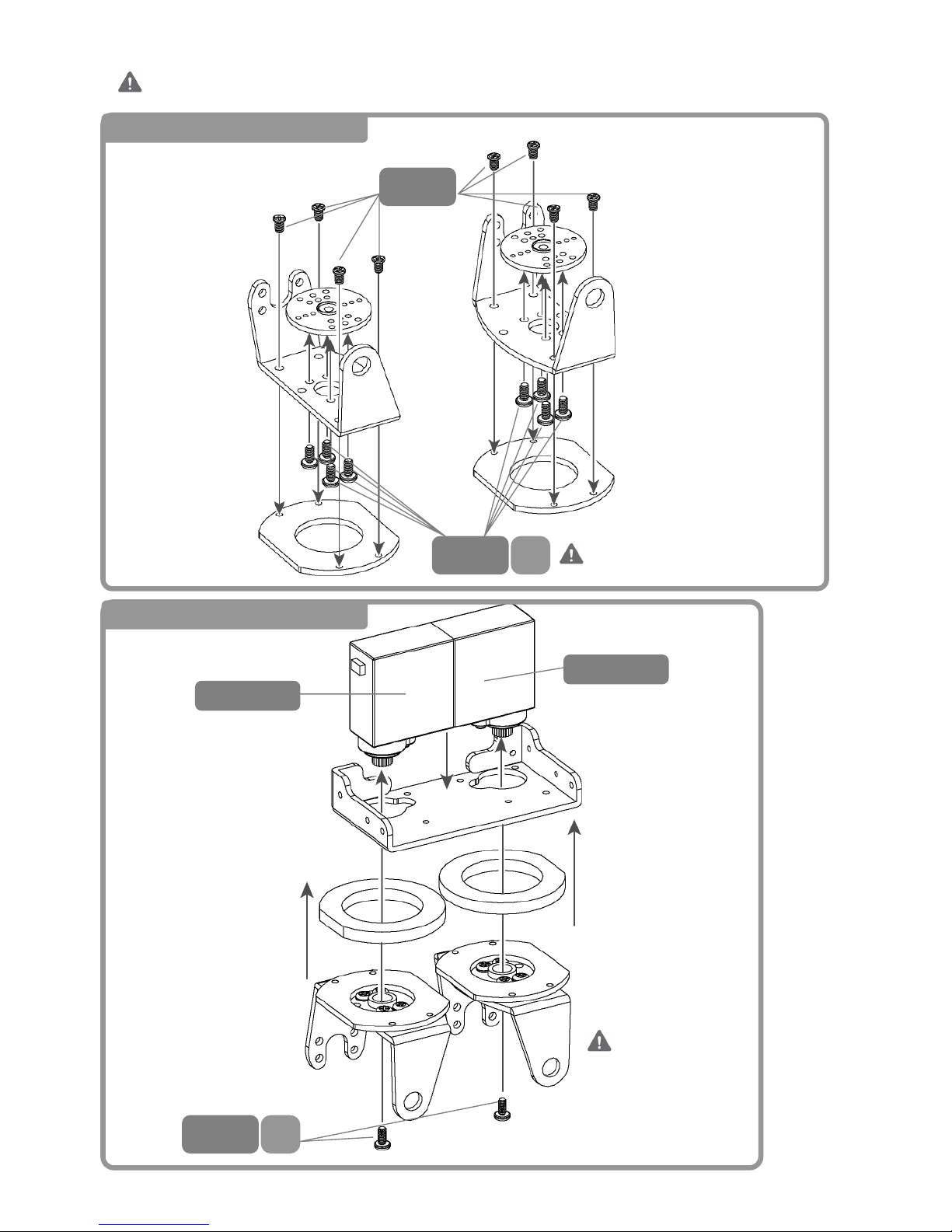
Steps 3, 4 and 5 outline the procedures for installing the yaw axis extension upgrade.
If you do not have the yaw axis extension upgrade, please start from Page 51.
3 Thigh Bracket Assembly
4 Attaching the Hip Yaw
Watch Direction!
CN1-S6
CN2-S6
3
M2-
4
M2-
S
4
M2-
S
<L>
<R>
<R>
<L>
Do NOT Strip the Screw
Threads!
Page 54
53
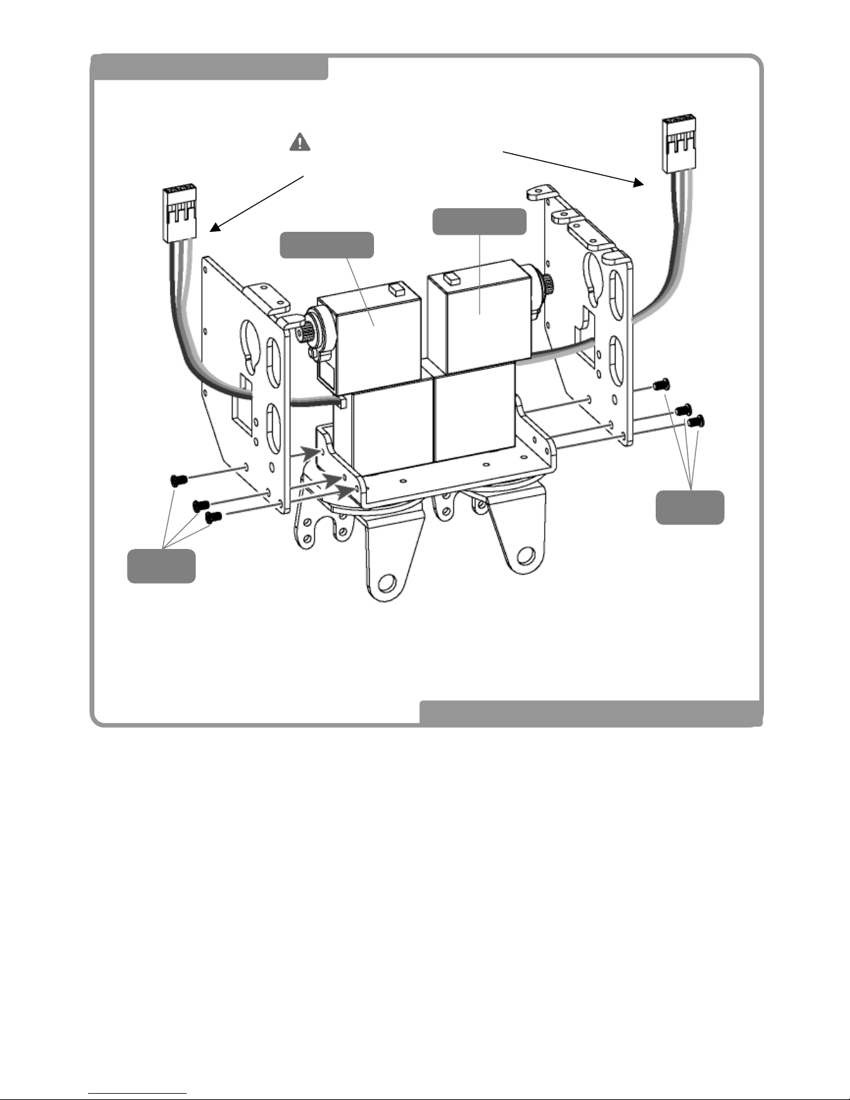
5 Mounting Arm Pitch Axis
Loop the cable through
the hole
3
M2-
3
M2-
→ 「Move to Step 6: Mounting the Battery Case」
CN3-S1
CN4-S1
Page 55
54
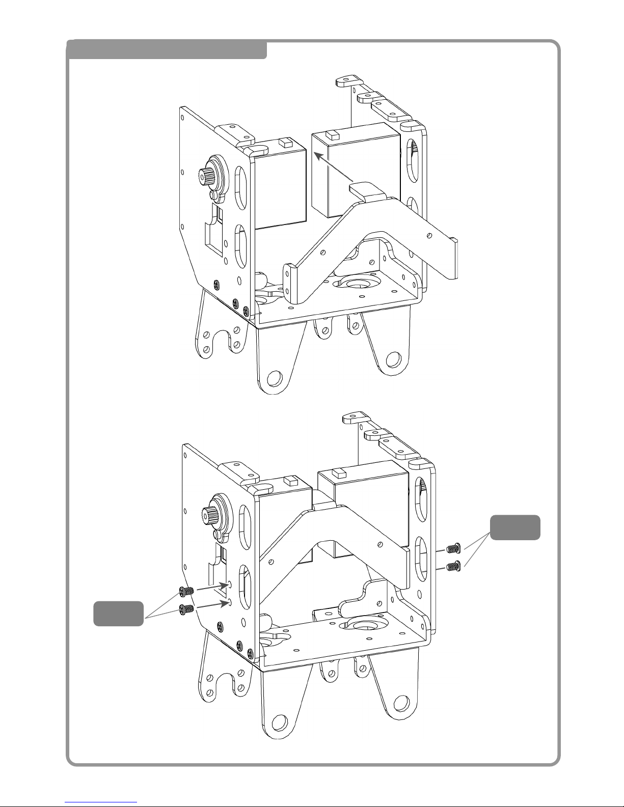
6 Mounting the Battery Case
3
M2-
3
M2-
Page 56
55
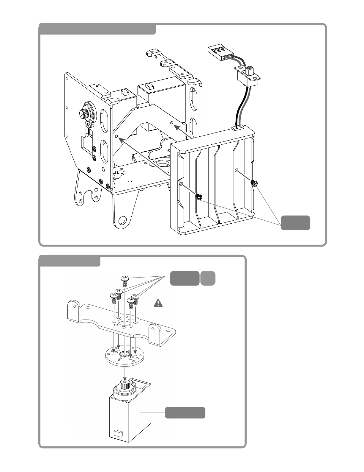
7 Mounting the Battery Case
3
M2-
8 Head Assembly
4
M2-
S
CN3-S6
Do Not Strip the Screw
Threads!
Page 57
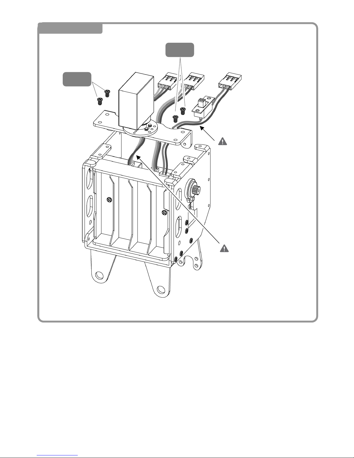
56
9 Head Assembly
3
M2-
3
M2-
Cables go UNDER the
head frame。
Make sure to loop the
head servo cable under
the frame!
Page 58
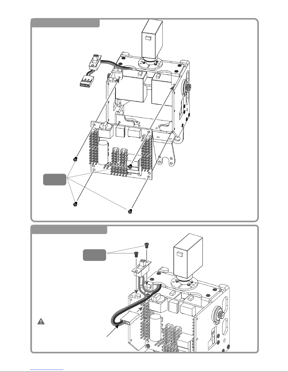
57
10 Attaching the CPU
11 Attaching the Power Switch
3
M2-
3
M2-
A
ttach the black side of the
servo cable toward the
outside of connector CN4-S6
Page 59
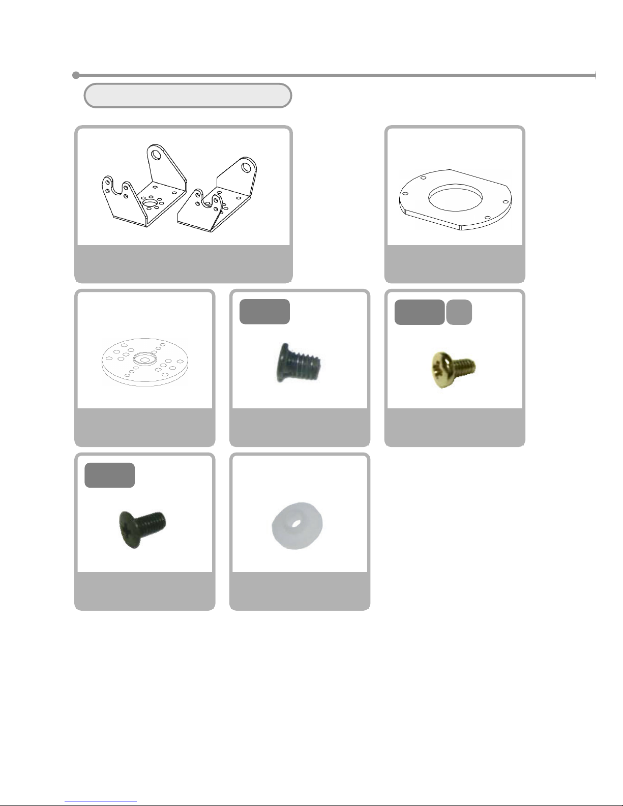
58
⑦ Arm & Leg Mounting
Please gather the necessary parts
VS-S020
Servo Horn
×6
Washer
×4
Screw NA
M2-3 Course Thread
×8
6
M3-
Screw NE
M3-6 Fine Thread
×4
3
M2-
4
M2-
S
Screw NC
M2-4 S Tight
×30
Bracket Set A
X 2 each
<L> <R>
Flat Washer
×2
Page 60
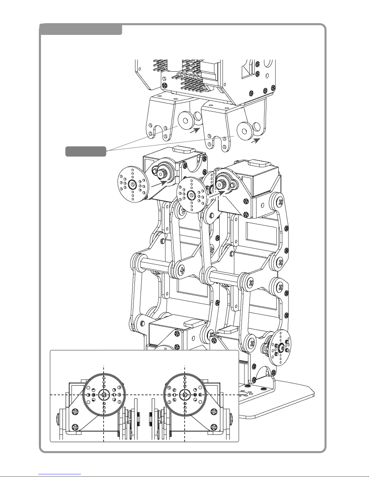
59
1 Attaching ① Leg
Direction for attaching the servo horn
Bushin
g
<Back>
Page 61
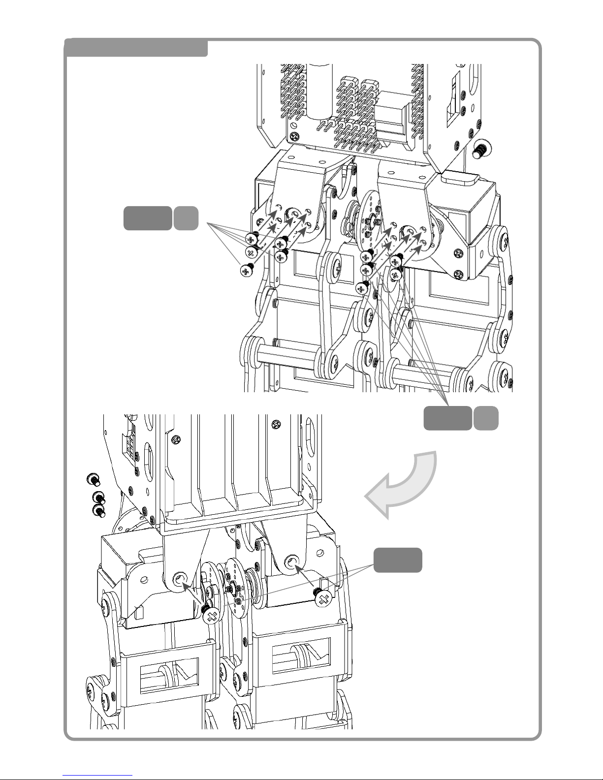
60
2 Attaching ② Leg
4
M2-
S
4
M2-
S
6
M3-
<Back>
<Front>
Inversion
Page 62
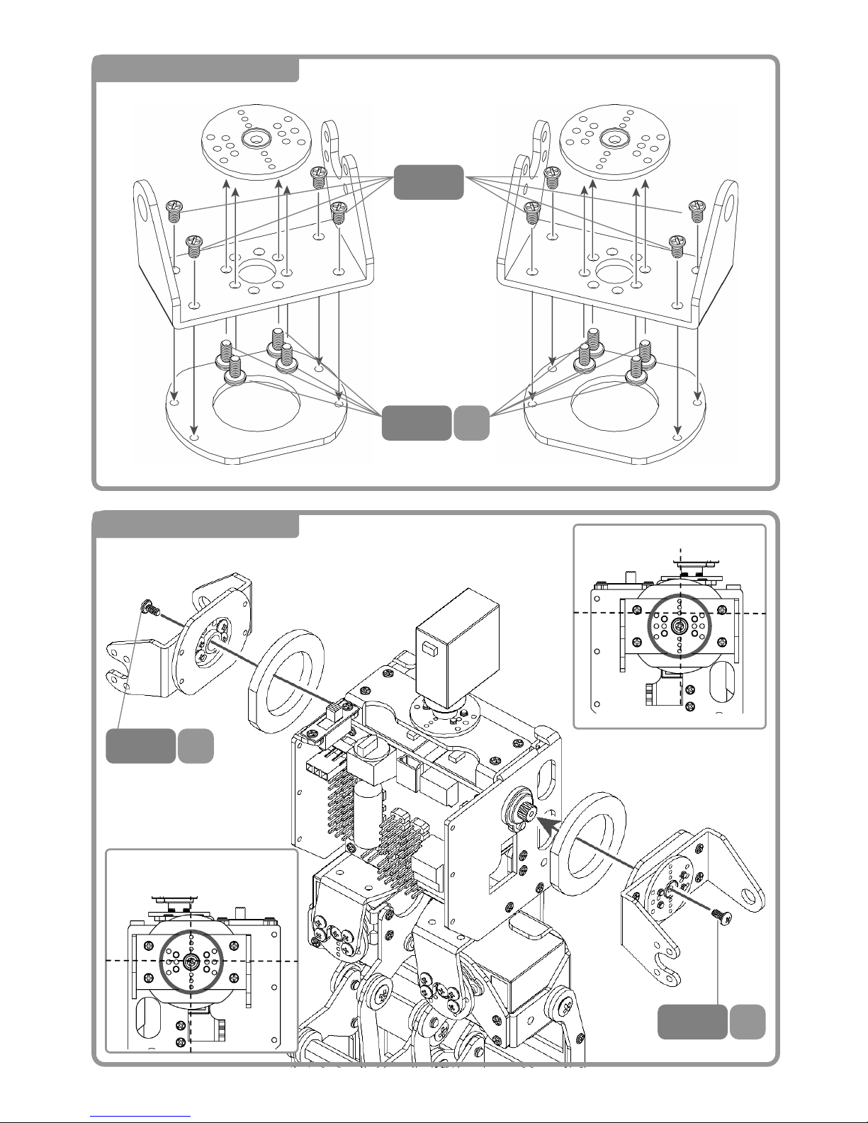
61
3 Mounting ① Arm
4
M2-
S
6
M3-
<L>
<正面>
<R>
3
M2-
4 Mounting ② Arm
4
M2-
S
4
M2-
S
A
ligning the servo motor
A
ligning the servo motor
Page 63
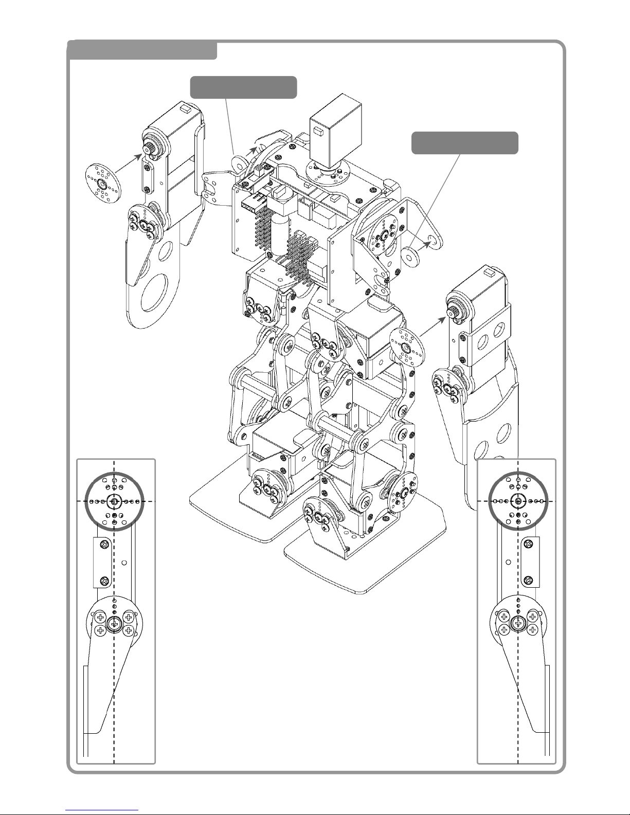
62
5 Arm ③ Mounting
Bushing
A
ligning the
servo motor
A
ligning the
servo motor
Bushing
Page 64
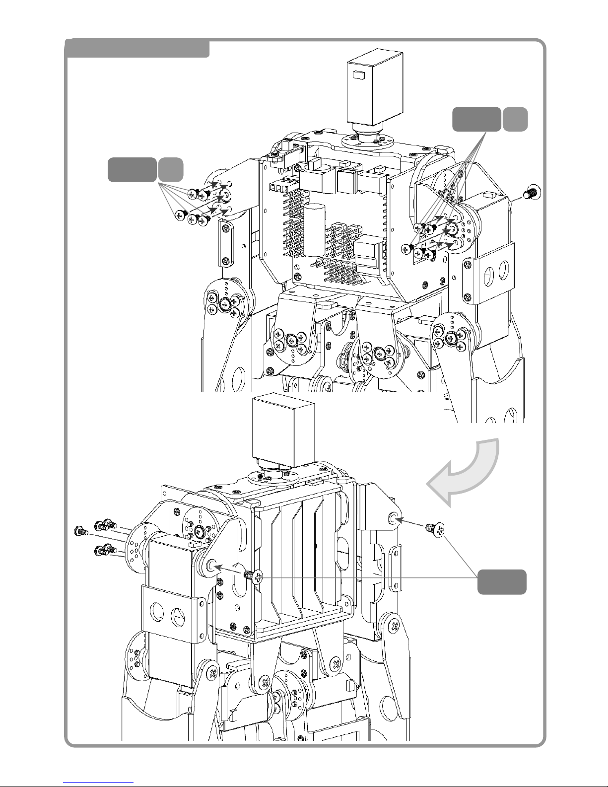
63
6 Mounting ④ Arm
4
M2-
S
4
M2-
S
6
M3-
反転
<Back>
<Front>
Page 65
64
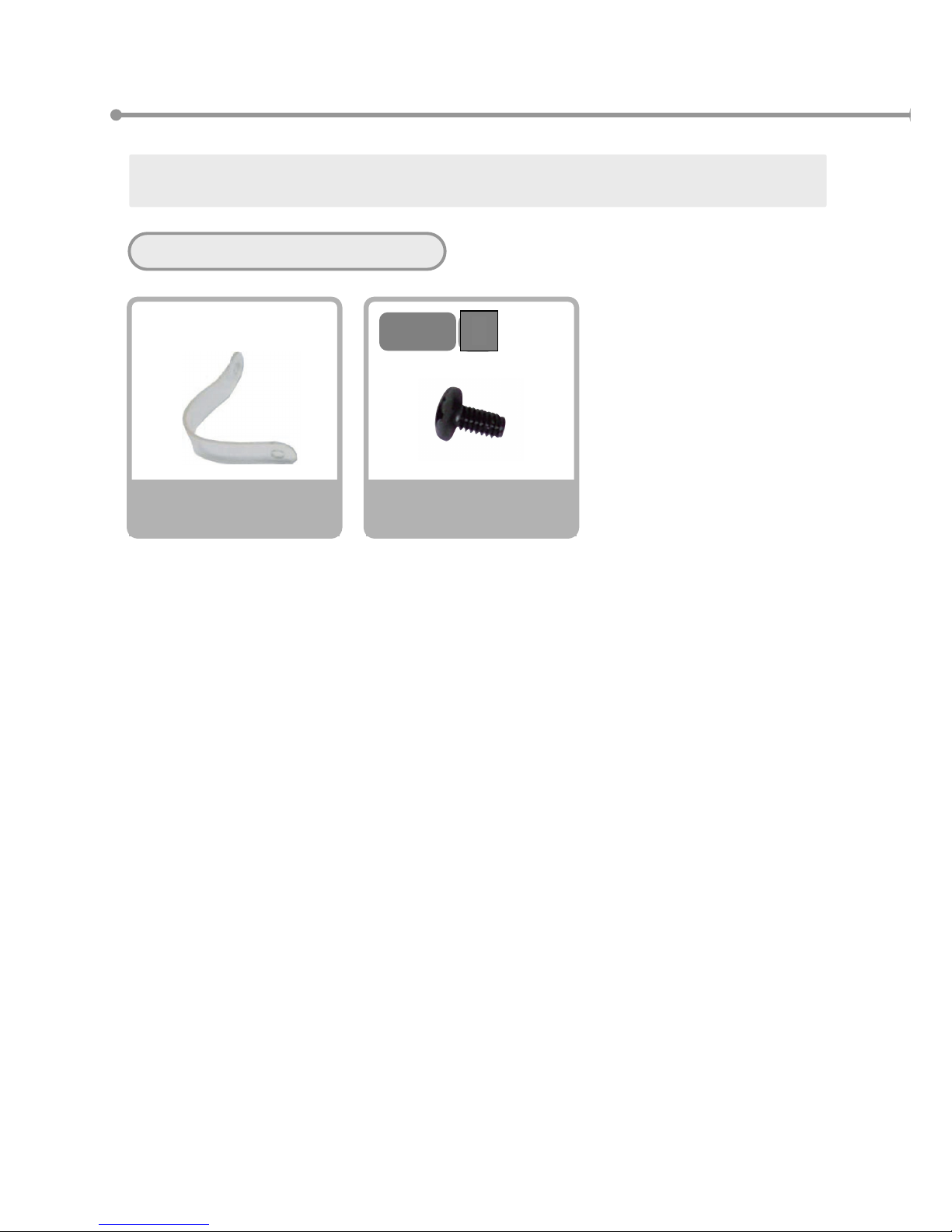
⑧ Securing the Wires
Please gather the necessary parts
5
M2-
バ
Screw ND
M2-5 Binding
×8
Wire Tie Down
×8
It is important to properly secure the wires after assembly in order to prevent unnecessary
accidents from wire tangling and snagging.
B
Page 66
65
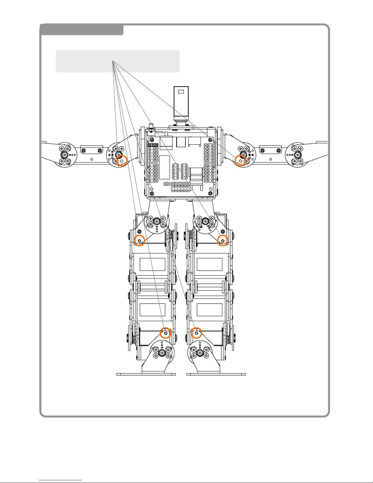
1 Fastening the Screws
Attached the screws the areas in the
○ below
Page 67
66
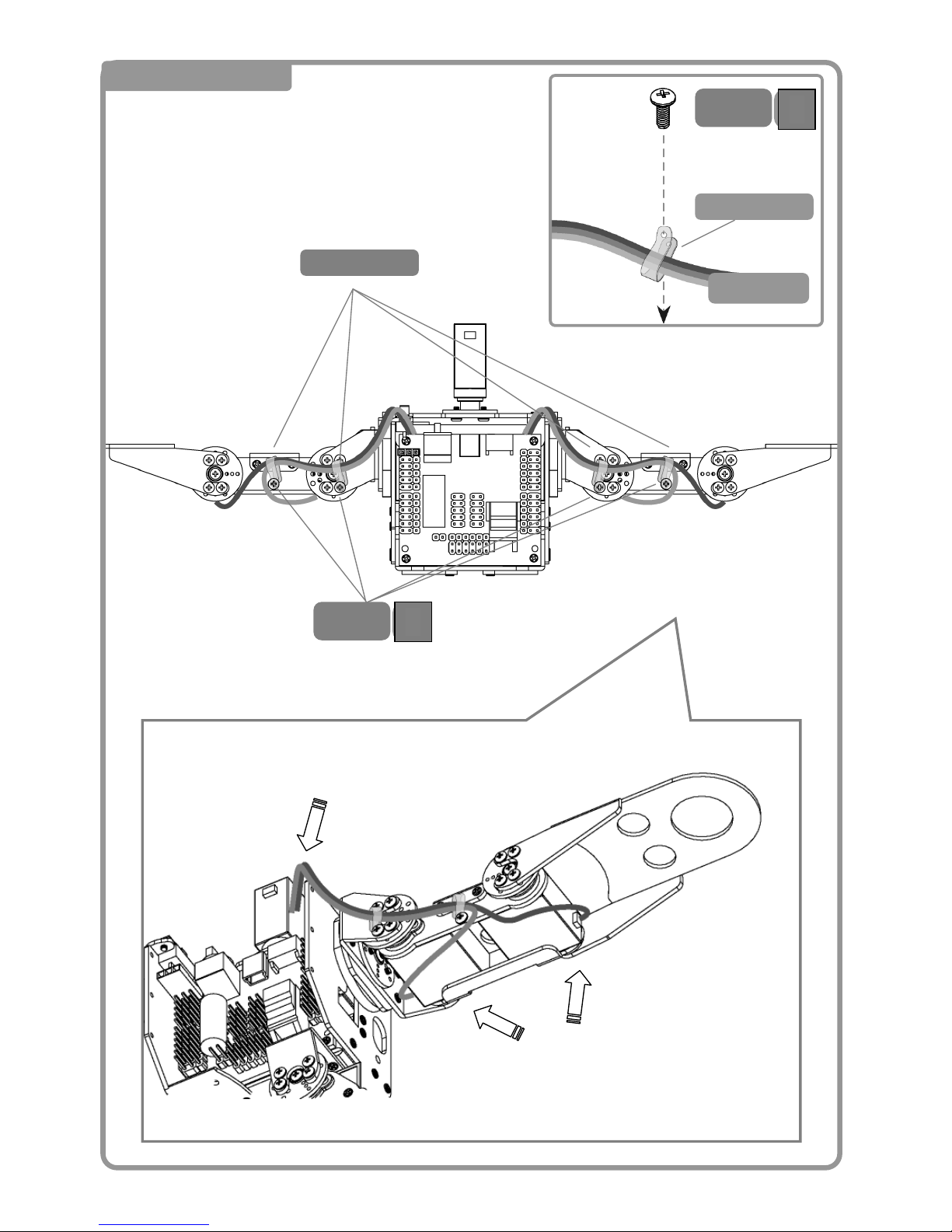
2 Wiring the Arms
From the bottom
Wire Ties
結束バンドの止め方
5
M2-
バ
Wire Tie
<背面>
5
M2-
バ
Through the Bottom
Wrap around the top
Cable
B
B
Page 68
67
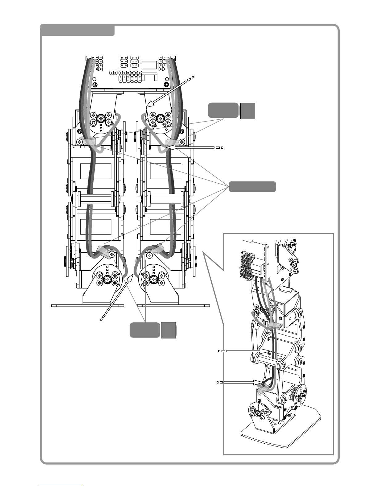
3 Wiring the Legs
<Back>
Wire Ties
5
M2-
バ
5
M2-
バ
Insert through the
middle of the frame
Through the middle
Through the bottom
Through
the middle
Over the top
B
B
Page 69
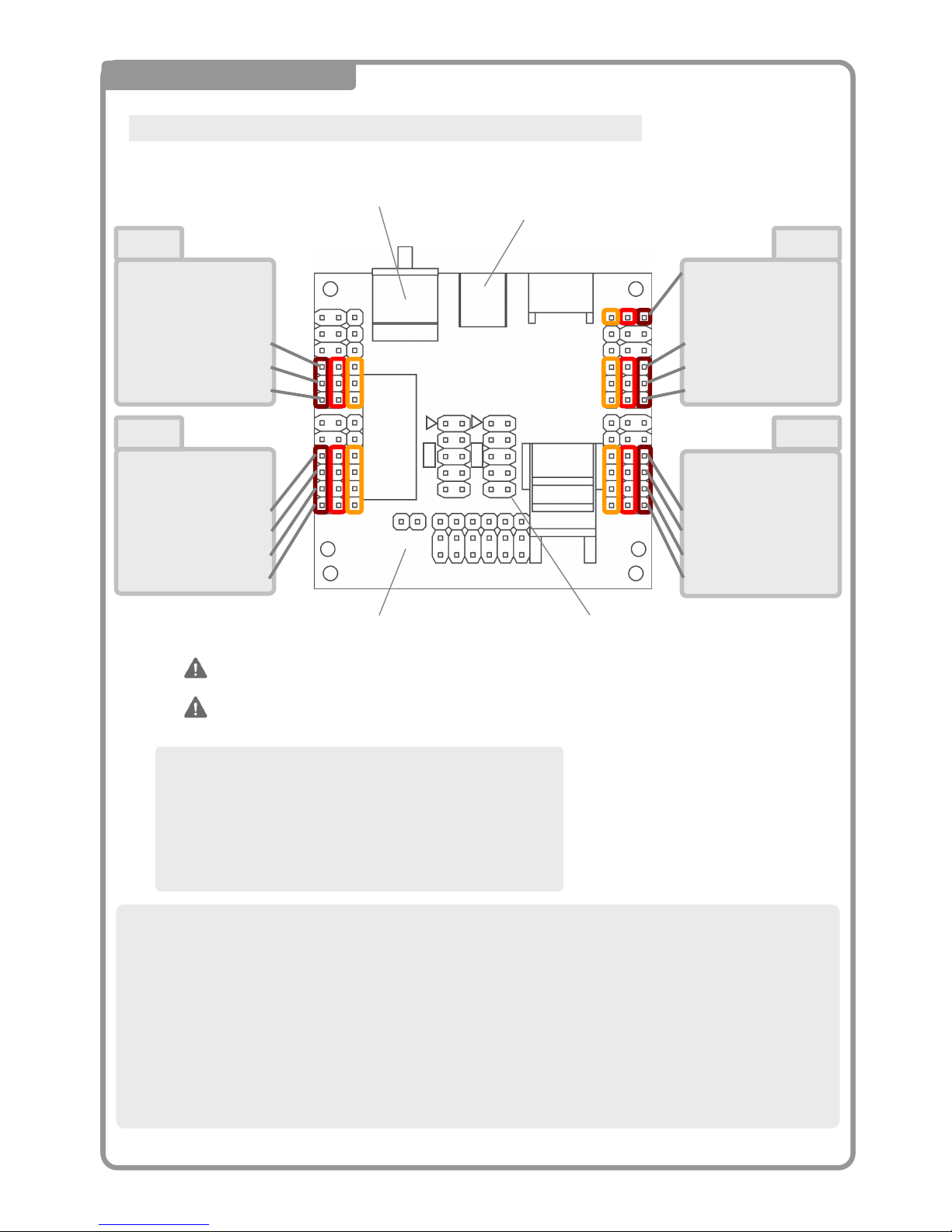
68
4 Cable Connection to CPU
S6:Head
S5:(右目LED)
S4:(右ハンド)
S3:Rt Elbow Roll Axis
S2:Rt Arm Roll Axis
S1:Rt Arm Pitch
S6:(Rt Leg Yaw)
S5:
S4:Rt Leg Roll
S3:Rt Leg Pitch
S2:Rt Ankle Pitch
S1:Rt Ankle Roll
S6:(Lt Leg Yaw)
S5:
S4:Lt Leg Roll
S3:Lt Leg Pitch
S2:Lt Ankle Pitch
S1:Lt Ankle Roll
S6:power cable
S5:(左目LED)
S4:(左ハンド)
S3:Lt Elbow Roll Axis
S2:Lt Arm Roll Axis
S1:Lt Arm Pitch
Connect all of the servo cables to the CPU board as shown
Incorrectly connecting the cables may lead to problems with the robot.
CN1 CN2
CN4 CN3
茶赤橙 茶赤橙 橙赤茶 橙赤茶
Connect the cable with the BROWN or BLACK lead facing OUT.
USB Port
Rotary Switch
CN6
CN7
CN11
CN1 CN2
CN4 CN3
CN5
<Connector Discription>
CN1~5 :Servo Motors、Power、VS-LED1
CN6 :Controller
CN7 :IXBUS(External devices, expansion board)
CN11 :Speaker Connector
<Connector Orientation>
Please use the following directions for connecting the cables listed below。
・Servo Motors :Connect with the brown or black cable facing out from the CPU board.
・Controller、IXBUS :Connect the △ symbol on the connector with the △ symbol in the figure.
Usually, △ aligns with Pin 1。
・Speaker :No polarity. Connect anyway you choose.
・VS-LED1 :Connect with the brown or black cable facing out from the CPU board。
Speaker Controller
Page 70
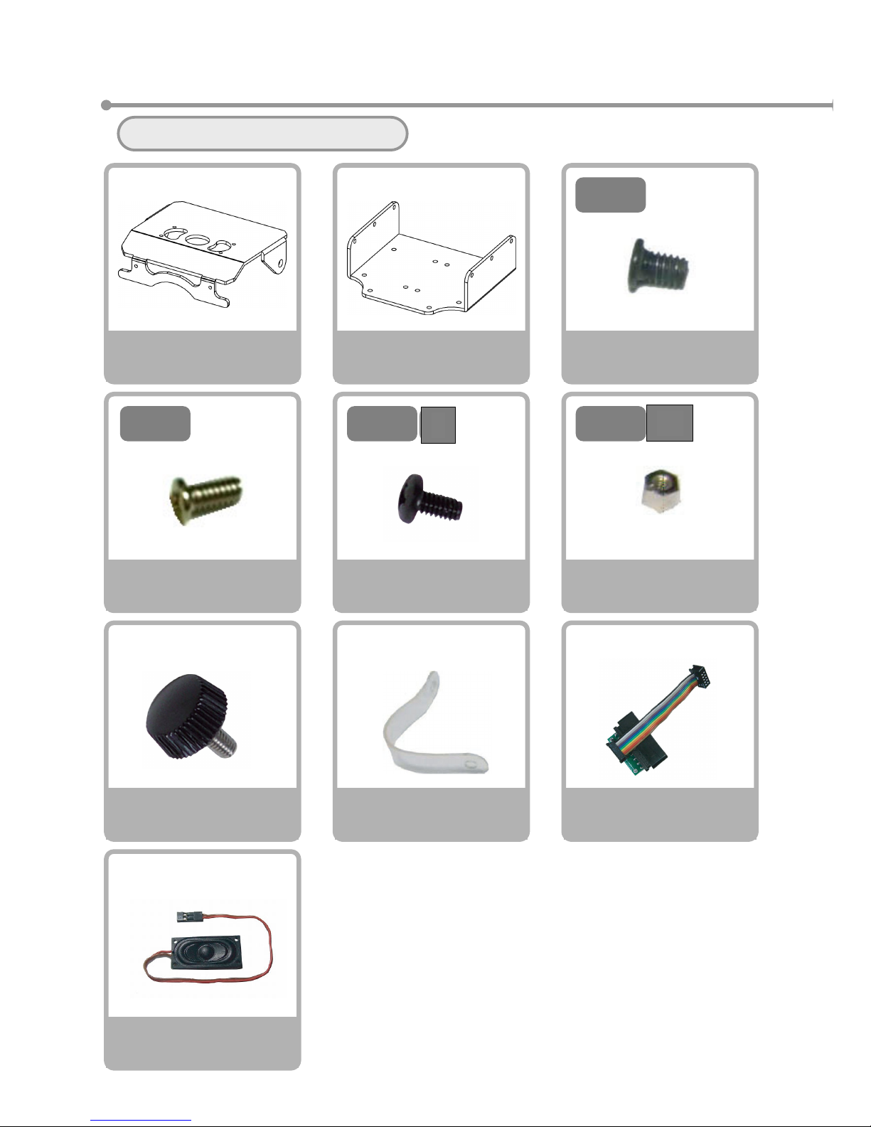
69
⑨ Securing the Front and Back Covers
Please gather all the necessary parts
5
M2-
バ
Screw ND
M2-5 Binding
×2
Cable Ties
×2
Front Cover
×1
Back Cover
×1
4
M2-
Screw NB
M2-4 Course Thread
×4
Screw NA
M2-3 Course Thread
×8
3
M2-
Twist Screw
×2
Speaker
×1
Connector and Cable
Gamepad Receiver
×1
Spacer A
M2-3 (Hex Spacer)
×2
3
M2-
ス
B
Sp
Page 71
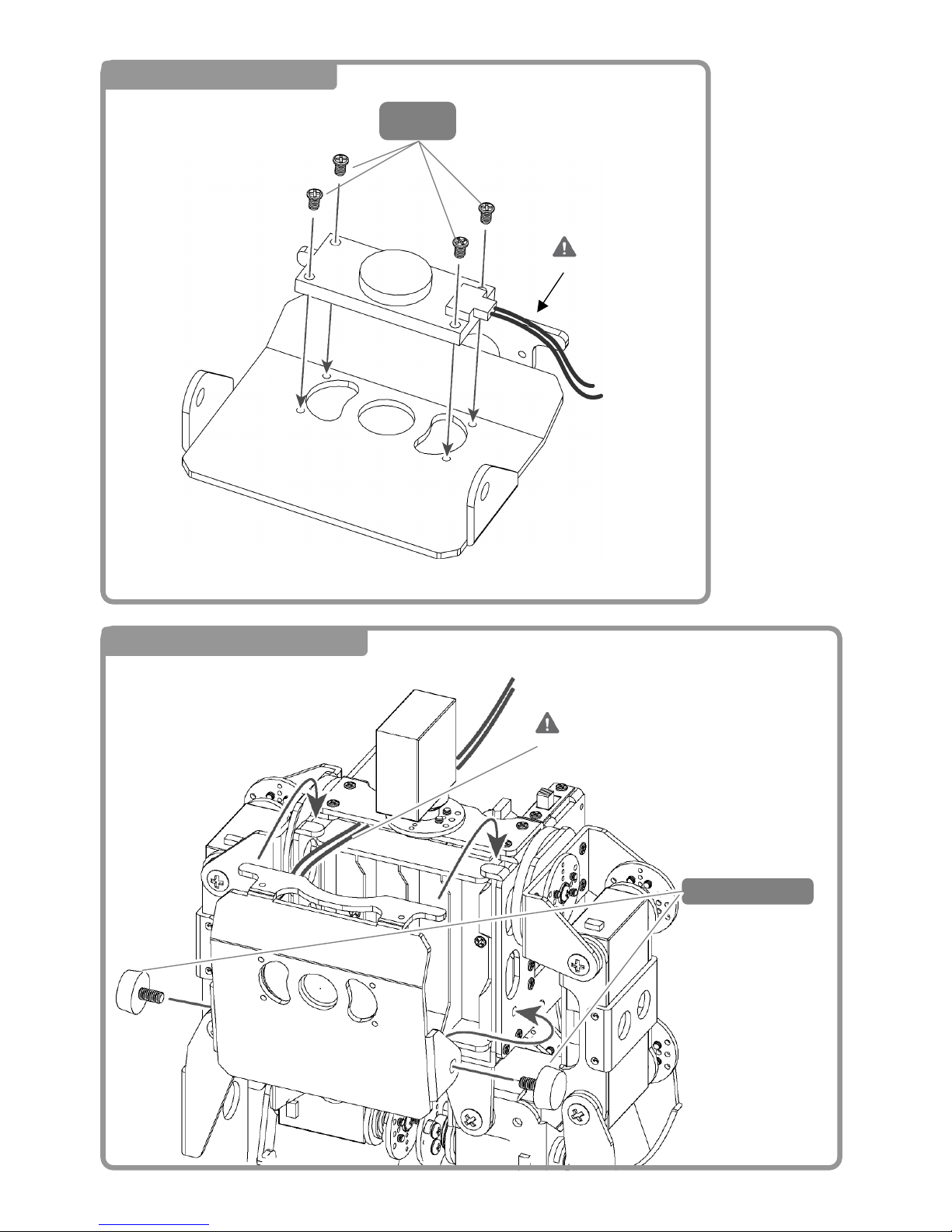
70
1 Attaching the Speaker
4
M2-
2 Attaching the Front Cover
Cable is on the
Right
Twist Screw
<正面>
Be careful not to crimp the
s
p
eaker cable with the frame
Page 72
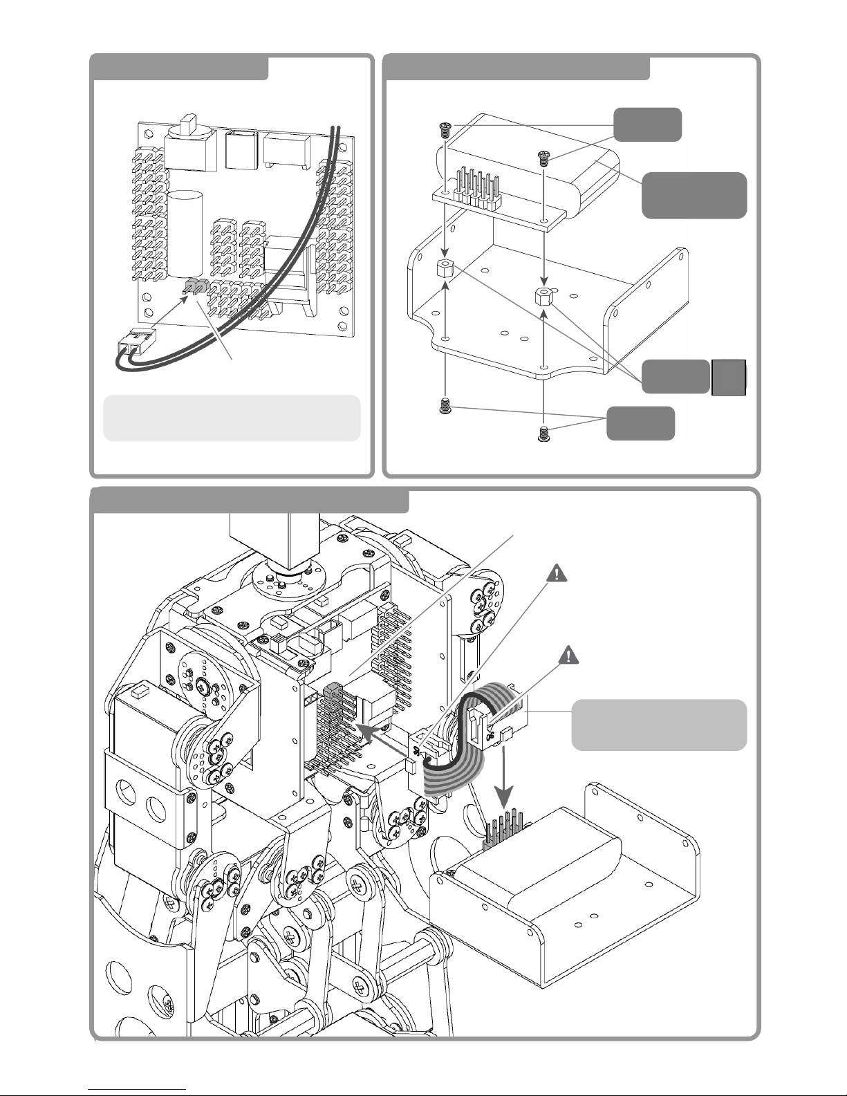
71
4 Attaching the Receiver Connctor
Receiver
Connector
3
M2-
ス
3
M2-
3
M2-
5 Connecting the Receiver IXBUS Cable
Line up the right side (▲)
of the cable as shown
Connector comes already
attached to the cable from the
factory
CN6
Connect to CN6 with the
brown cable (▲) facing up.
3 Speaker Connection
Connect the speaker cable to CN11.
There is no polarity for direction.
CN11
Page 73
72
6 Wiring Together
7 Attaching the Back Cover
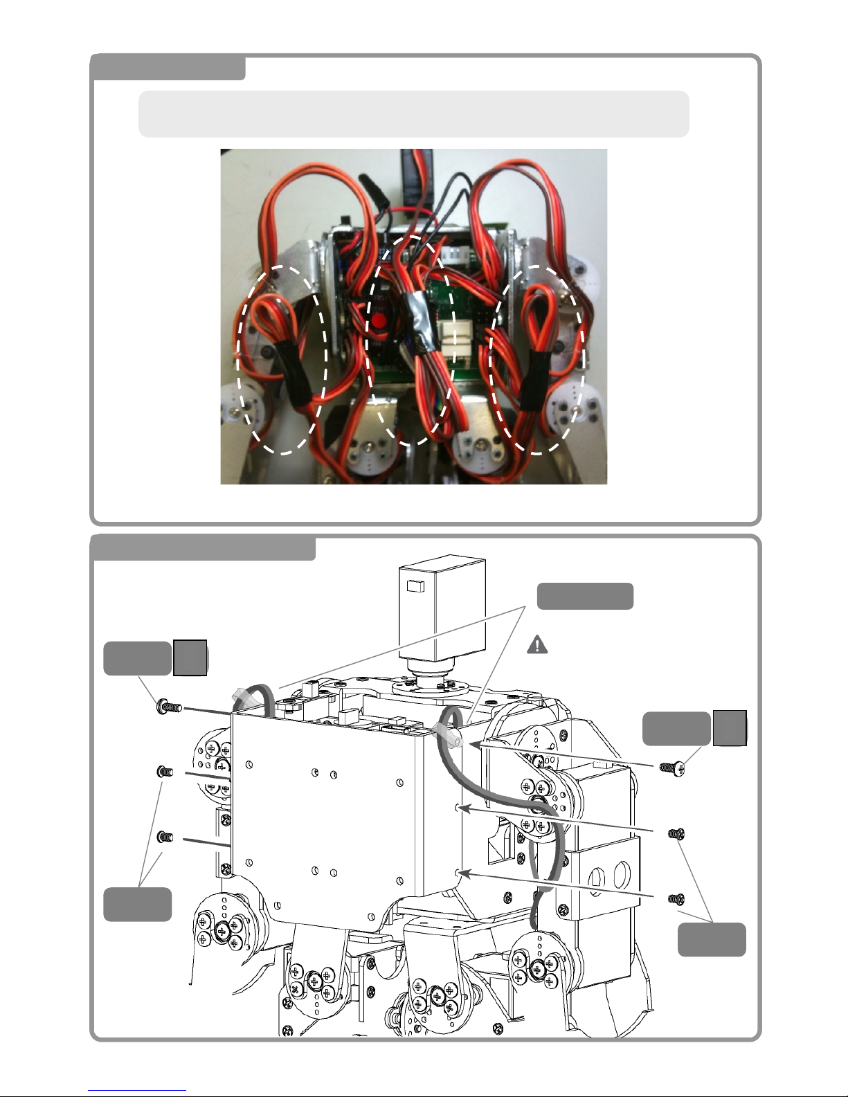
Taping down the excess cable.
※Taping is not required, however it makes covering the back of the robot easier.
The cable tie has holes in
both ends for t
ying
down
Cable Tie
3
M2-
3
M2-
5
M2-
バ
5
M2-
バ
B
B
Page 74
73
4.Servo Motor Position
Correction
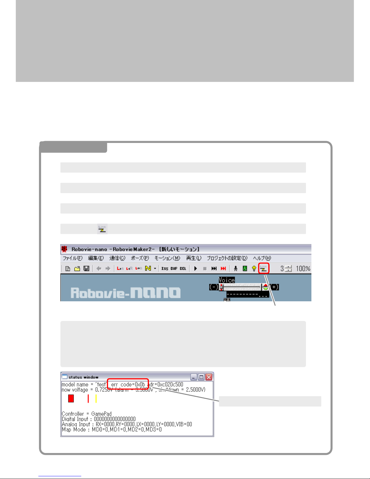
If you turn the robot’s servo motors ON immediately after assembly, the limbs will move into an
awkward posture and the robot will not move correctly. Please correct the position of the servo
motor according to the following steps
4. Click the button to link the software with the CPU board.
1. Remove the front cover of the robot to insert a nickel-metal hydride rechargeable battery
2. Connect the robot’s CPU board to the PC with the USB cable.
3. Open RobovieMaker2 on the PC
通信ボタン
⑤Confirm the 「status window」 error code is 「0x0b」
※When the 「VS-IX001」gyro/accelerometer chip is connected, the error code will be 「0x00」
If the error reads anything other than 「0x00、0x0b」、you may have some kind of problem。Please refer
to the RobovieMaker2 reference manual。
Confirm the error code is 「0x0b」
1 PC と接続する
Page 75
74
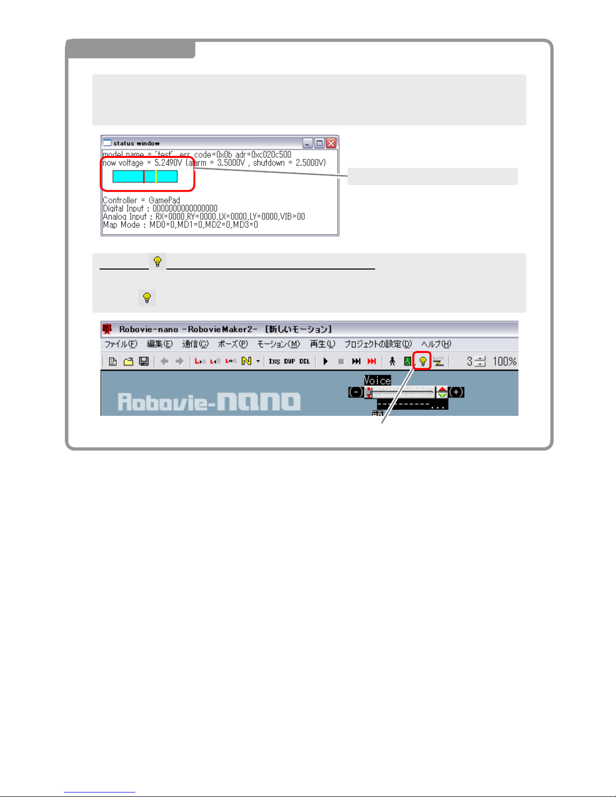
Press the button to apply power to the servo motors.
If, at the moment you push the button and the servo motors go into an unnatural pose, immediately
push the button to turn OFF the servo motors, as you may damage the motors.
2 Checking the Servos
Turn on the robot’s power switch. At this time, please check the 5v voltage as indicated below. If you
experience a low voltage (3v, etc.), there may be a problem with battery, the battery connection or the
servo motors may be improperly connected. Please switch off immediately
Check that you have 5v in the window
Servo Motor ON/OFF Button
Page 76
75
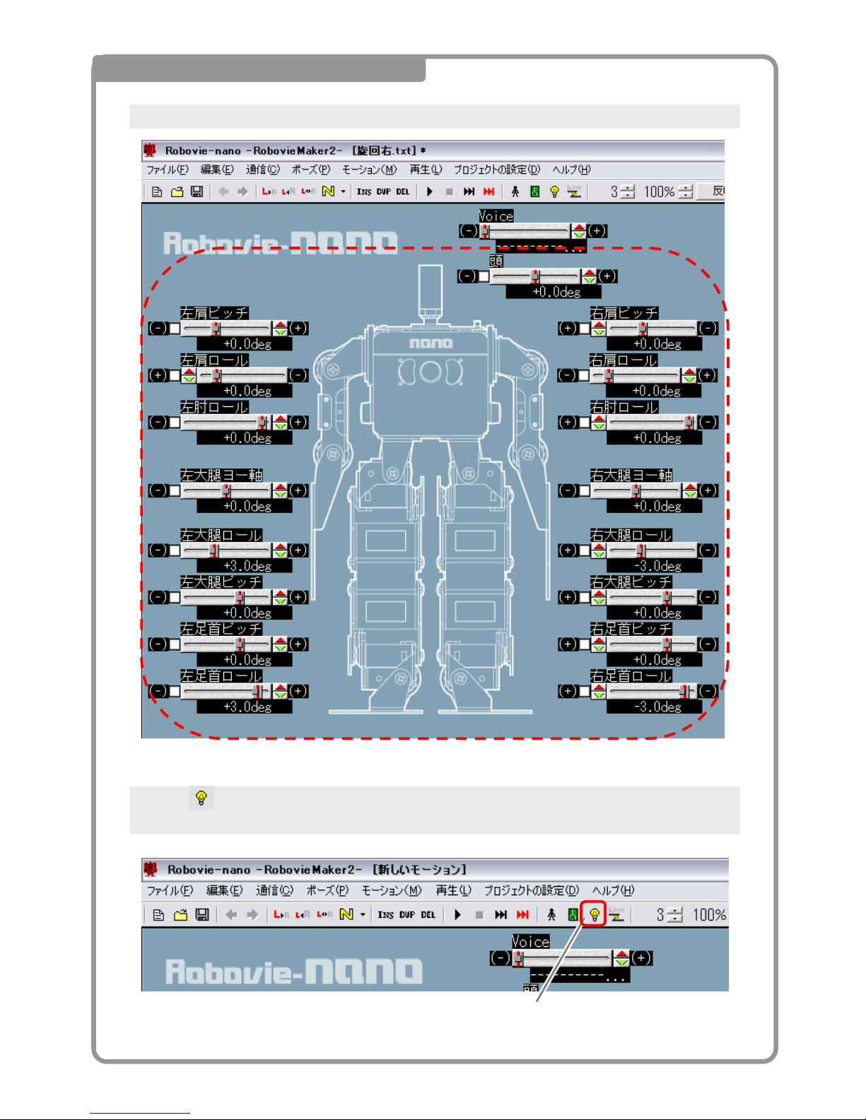
3 About the Slider
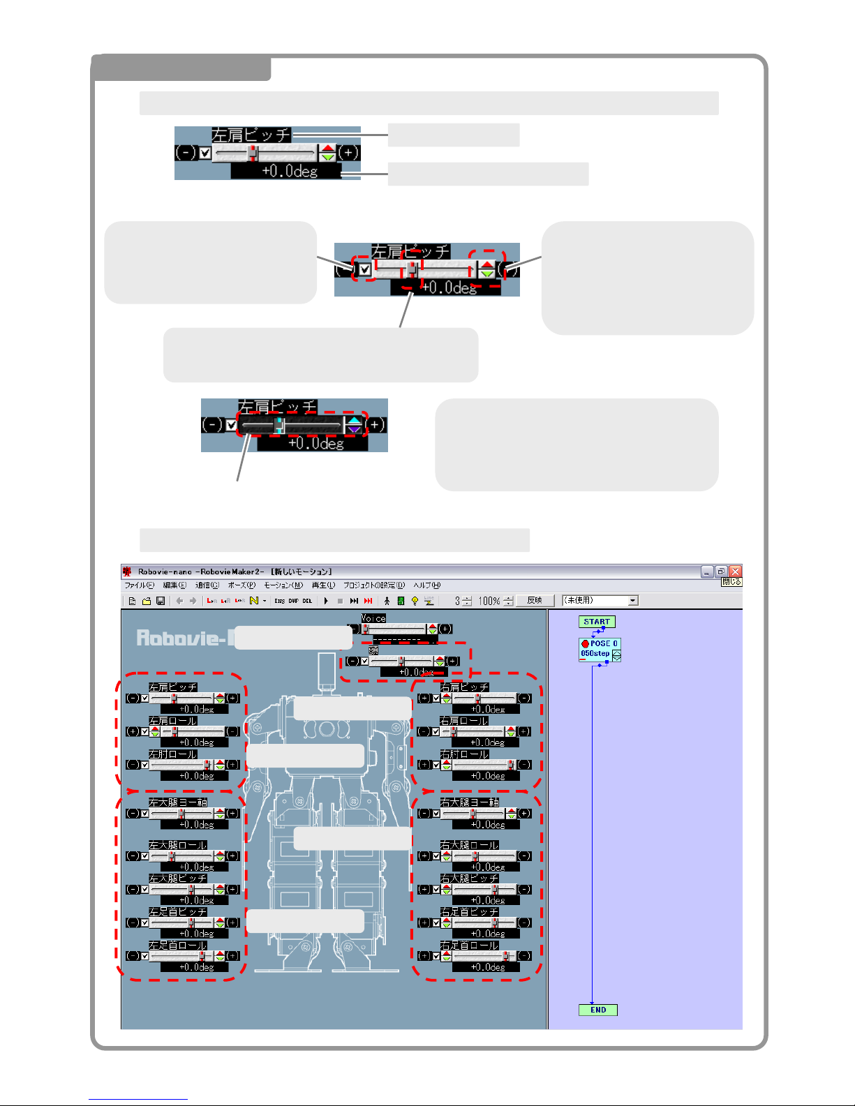
Pose sliders will appear as shown in the image below.
Left Leg Slider
Right Leg Slider
Right Arm Slider
Left Arm Slider
Head Slider
Turn ON/OFF the servo motor by
checking or unchecking the box.
Check in the box is live power.
Click the top half and bottom
half of the spin button to
fine-tune the angle of the
servo motor
By moving the slider left or right, you can
change the angle of the servo motor.
Y
ou can change the state of the slider b
y
clicking on the bar and dragging it left
or right with your mouse, or clicking on
the slider background and scrolling the
bar with the mouse wheel.
Background will turn black with the
slider is active
Specify the angle of the servo motor to change the value of the slider.
Slider Name
A
ngle of the Servo Motor
Page 77
76
4 Power the Servo Motors One at a Time
Uncheck all of the boxes to remove power from the servo motors
Push the button on the software to confirm no moving servos.
※Even if you turn the robot ON, the servos will not have power.
Servo ON/OFF Button
Page 78
77
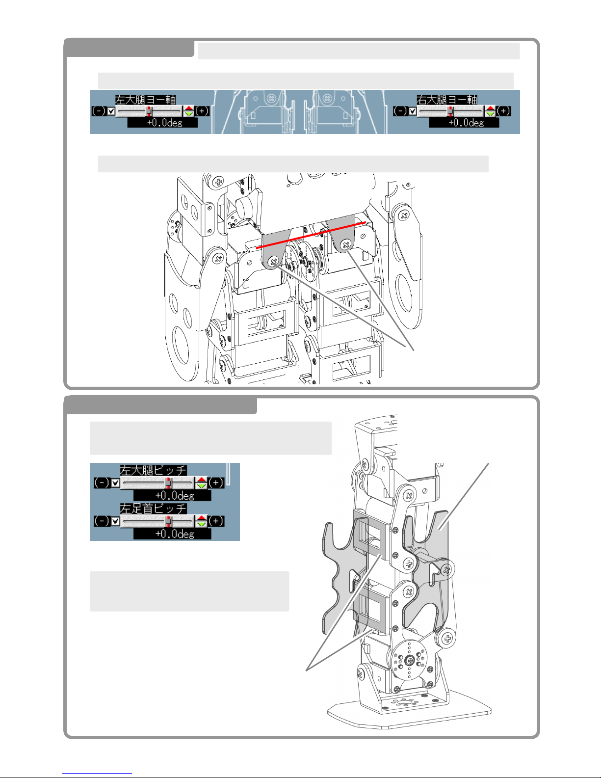
5 Leg Yaw
Please continue only if you have purchased a yaw extension kit for your robot.
「Place a check in the LEFT and RIGHT yaw access boxes and click the servo motor power button.
As shown below, "yaw left thigh", "yaw right thigh," lets you adjust the angle of the servo.
Align the two sides as shown.
6 Left leg pitch axis
Place a check in the 「Left Leg Pitch」、「Left Ankle Pitch」
boxes and push the servo motor power button.
Use the provided jig as shown to adjust the
initial position of the servos.
Align the 2 sides as shown
Y
ou have aligned the legs
properly if the jig is flush
against the two brackets.
Page 79
78
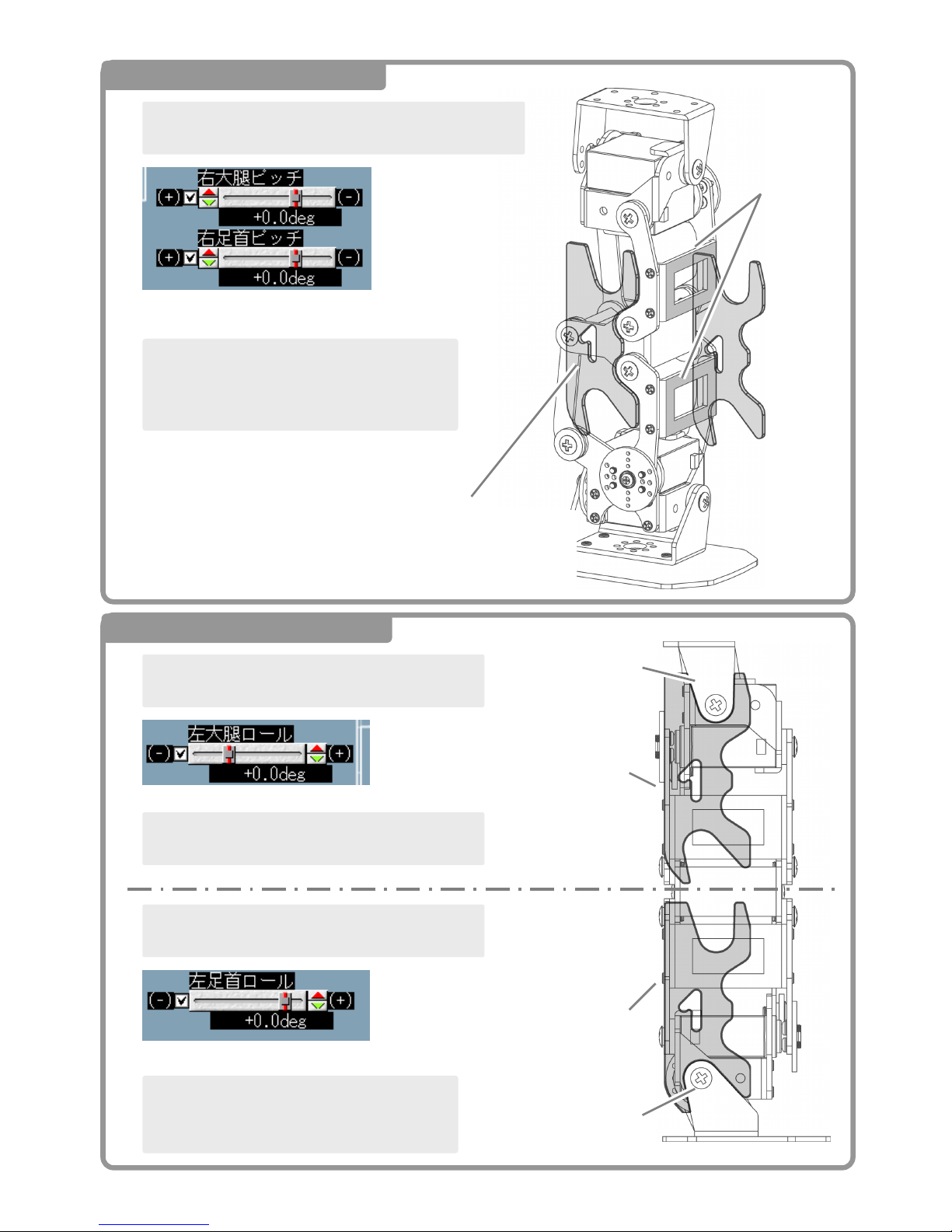
7 Pitch right leg axis
Place a check in the 「Right Leg Pitch」、「Right Ankle
Pitch」boxes and push the servo motor power button.
Use the provided jig as shown to adjust the
initial position of the servos on the right leg.
Align the 2 sides as
shown
Y
ou have aligned the legs
properly if the jig is flush
against the two brackets.
8 left leg and roll axis
Place a check in the 「Left Leg Roll」box and push
the servo motor power button.
As shown on the right, using a jig for adjusting the
initial position lets you set the proper angle
Place a check in the 「Left Ankle Roll」box and
push the servo motor power button.
As shown on the right, using a jig for adjustin
g
the initial position lets you set the prope
r
angle.
A
pply the jig to the
bracket without an
y
gaps
A
pply the jig to the
bracket without an
y
gaps
A
djust the servos
to be parallel with
the jig, as shown.
A
djust the servos
to be parallel with
the jig, as shown
Page 80
79
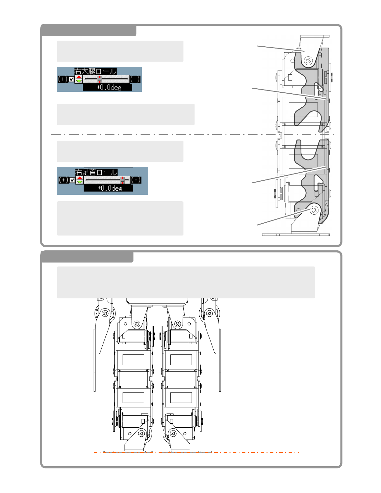
9 Right leg and roll axis
Place a check in the 「Right Leg Roll」box and
push the servo motor power button.
As shown on the right, using a jig for adjusting the
initial position lets you set the proper angle
Place a check in the 「Right Ankle Roll」bo
x
and push the servo motor power button.
As shown on the right, using a jig for adjustin
g
the initial position lets you set the proper
angle.
A
pply the jig to the
bracket without an
y
gap
s
A
pply the jig to the
bracket without an
y
gaps
A
djust the servos
to be parallel with
the jig, as shown
A
djust the servos
to be parallel with
the jig, as shown
10 Check the roll axis
Make sure the alignment of the LEFT and RIGHT feet are as shown below.
If not, tweak the positions of each leg with the sliders until you achieve alignment like the image
below.
Make sure both the left an
d
right legs are straight.
Page 81
80
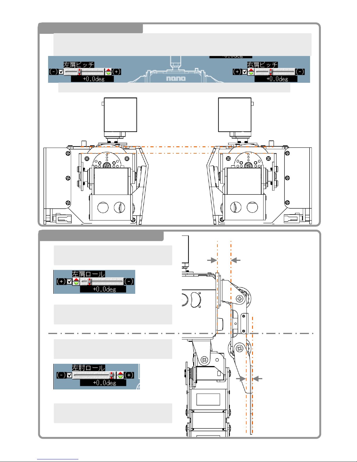
11 Shoulder Pitch Correction
Place a check in the 「LEFT Shoulder Pitch」 and 「Right Shoulder Pitch」 boxes then click the servo
power button
Align the 「LEFT Shoulder Pitch」 and 「Right Shoulder Pitch」 as shown below.
A
djust so that the frame
and body are parallel to
the upper bracket of the
shoulder
12 Left Arm “Shoulder” Roll Axis
Place a check in the 「Left Arm Roll」box and
push the servo motor power button
Adjust the shoulder roll as shown on the image
to the right
Place a check in the 「Left Elbow Roll」box and
push the servo motor power button
Adjust the elbow roll as shown on the image to
the right
A
djust the inner side of the
arm and torso to be
parallel.
(Torso and arm spacing is
about 15mm)
A
djust the outside o
f
the arm and the han
d
to be parallel.
Page 82
81
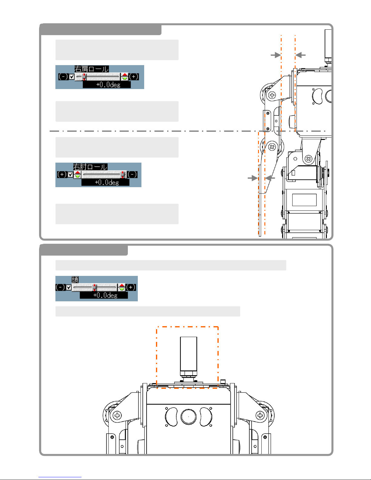
13 Right Arm “Shoulder” Roll Axis
Place a check in the 「Right Arm Roll」box and
push the servo motor power button
Adjust the shoulder roll as shown on the image
to the right
Place a check in the 「Right Elbow Roll」bo
x
and push the servo motor power button
Adjust the elbow roll as shown on the image to
the right
A
djust the inner side of the
arm and torso to be parallel.
(Torso and arm spacing is
about 15mm)
A
djust the outside o
f
the arm and the han
d
to be parallel.
14 Head Yaw Axis
Place a check in the 「head yaw」 box and click the servo motor power button
Adjust the head yaw as shown on the image below.
The head should be looking
forward completely as
shown.
Page 83
82
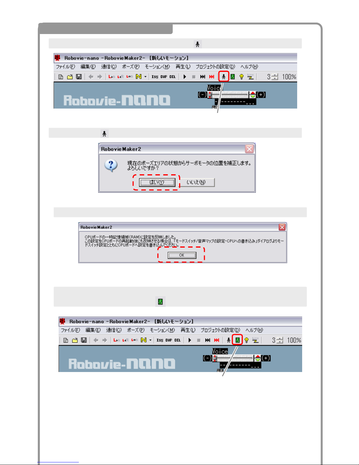
15 Servo Initial Position Adjustment
Servo initial configuration button
After all the servo motors have been configured click the button.
A
fter clicking the button, the following dialogue will appear. Click Yes.
The writes the configuration to the RAM (temporary memory). Click OK.
Since the settings have only been written to the RAM at this time, all settings will be lost once powe
r
is disconnected. To finalize, press the button to write the settings to the CPU’s ROM.
Mode Switch/ Audio Settings Write button
Page 84
83
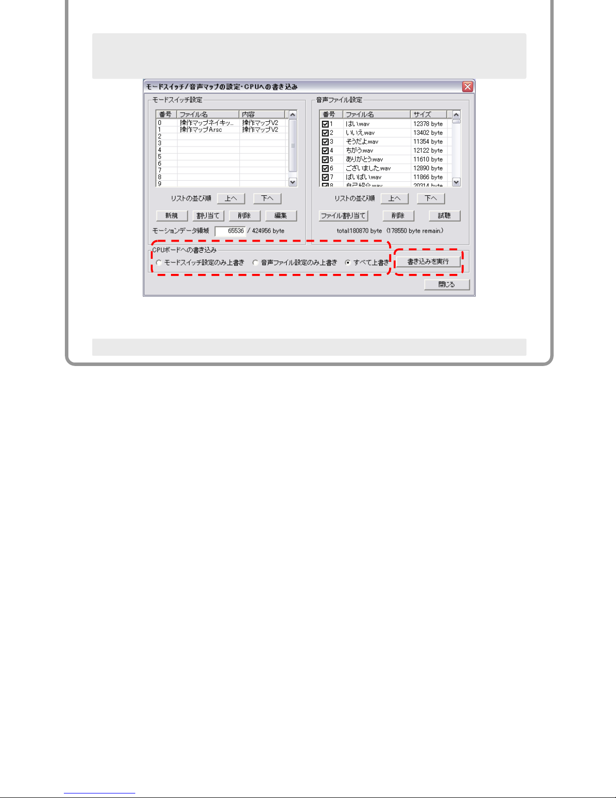
In the CPU Write Settings Dialogue Window, click "Overwrite all" and select "Run" to begin the write
press.
Once the files have been written to the CPU board your robot assembly is complete.
Page 85
84
5.Gamepad Operations
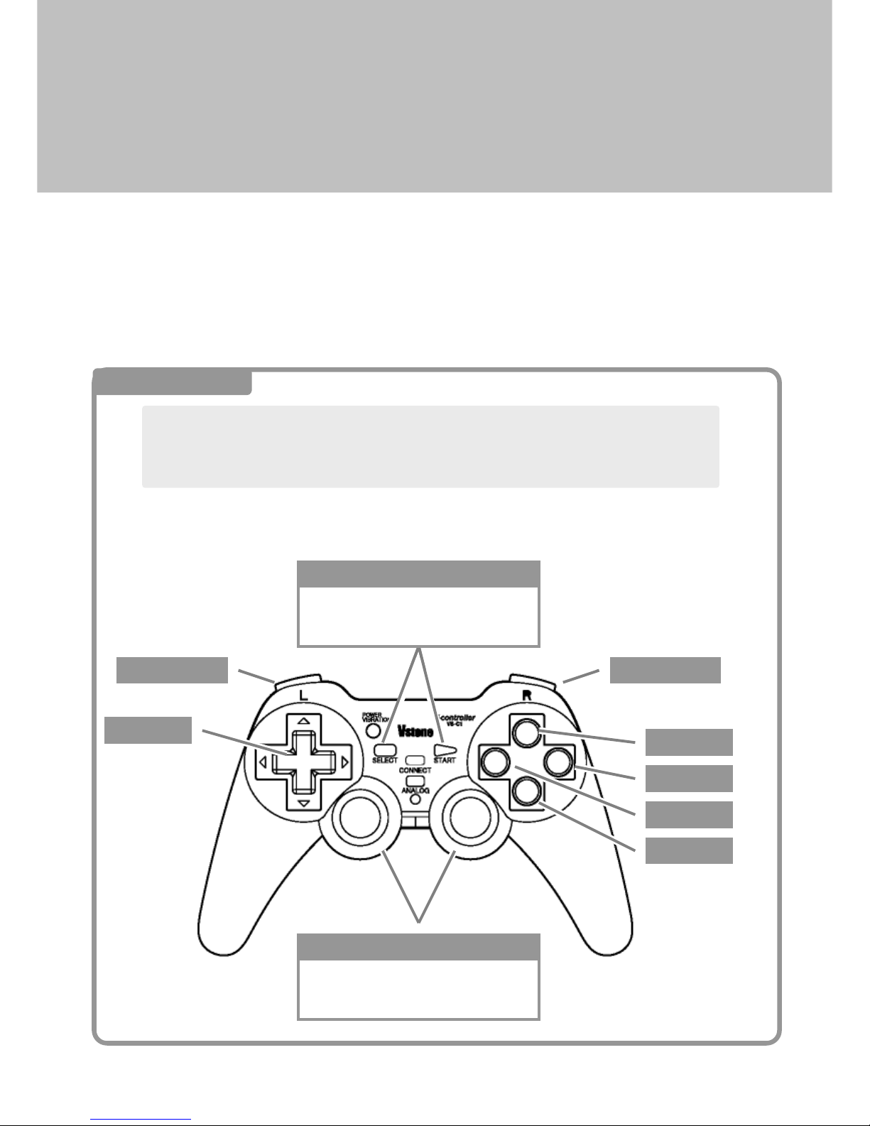
Motion files for operating the robot are uploaded to the CPU board by default when the initial settings are
written. You can control the robot with the PS2 wireless remote controller if a receiver is connected.
At this time, the only controller supported is the wireless robot gamepad controller"VS-C1", manufactured by
Hori "Vibration Wireless Anaheim 2 TURBO”. If you want to connect with the game pad, please attach the
connector and associated receiver to the inside of the robot’s body. Please see the assembly manual.
1 Button
方向キー
L1,L2
R1,R2 ボタン
●ボタン
▲ボタン
×ボタン
■ボタン
Pressing in the sticks function as
the L3 and R3 buttons.
アナログスティック、L3,R3 ボタン
SELECT+START turns ON/OFF the servos.
SELECT+○△□×Map Button Switch
SELECT、START
The function of the game pad buttons are as follows. To apply power ON to the robot,
first press and hold the SELECT button then press the START button.
※ This will not activate the robot when the USB cable is connected
Direction
L1,L2 Button R1,R2 Button
●button
▲button
×button
■button
Analog Stick、L3,R3 Button
SELECT+START turns ON/OFF the servos.
SELECT+○△□×Map Button Switch
SELECT、START
Page 86
85
2 Selecting the Maps
The controller can switch the map manually during the operation. In other words, you can get the
same button to behave differently and have a completely different function. The standard
configuration is equipped with the following three maps from the controller SELECT button + △ ○
×. The operator can switch between maps by pressing any one of button configurations above.
Basic motions and behaviors such as bowing, self introduction, cart wheels and
walking have all been programmed into this map by default.
Basic Operation SELECT + ▲
Soccer SELECT + ●
Battle SELECT + ■
Punching, throwing, takedowns and other defensive features are included.
Shoot, kick and goal keeper functions have all been programmed into this map.
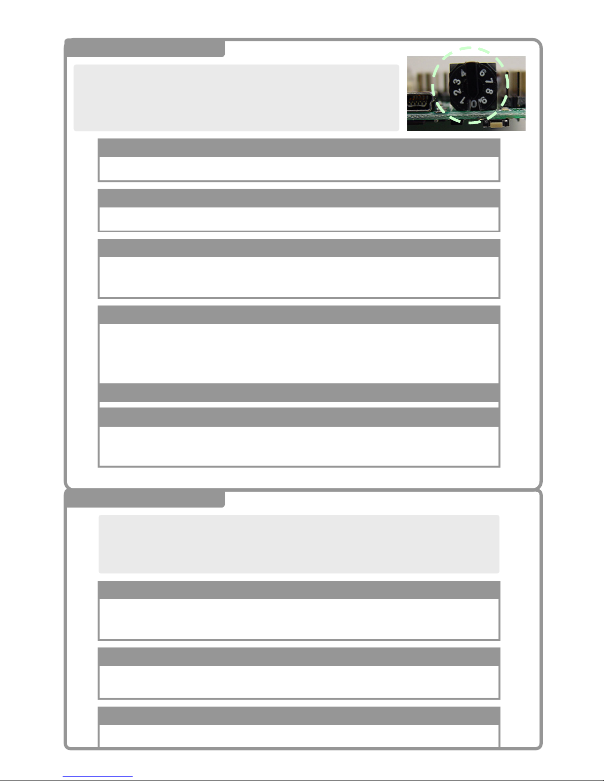
2 Mode Switch
The board has a CPU mode switch as shown on the right. This is intended to
change the mode of operation for various demonstration maps and auto-run
routines. With the map and auto demo, you can register up to 10 operations.
Robovie-nano is written in the following modes by default as shown below:
Control maps in this mode should not have any optional parts.
0: Basic (Plain) Control Map
This is used for operations when robot is wearing the suit.
1: External Robot Control Map
This map contains the motion files to use with the yaw axis version of the robot.
2: Yaw Axis Control Map
This map is used when the 「VS-IX001」 gyro/accelerometer chip is installed. With the
gyro, walking is more stable and the robot will use the accelerometer to detect when it
has fallen over and automatically stand back up.
3: Gyro Sensor Control Map
Servo motors will automatically power ON and begin self introduction.
Servo motors will automatically power OFF once finished.
9: Auto Demonstration Self Introduction
4~8 (Not Used)
Page 87
86
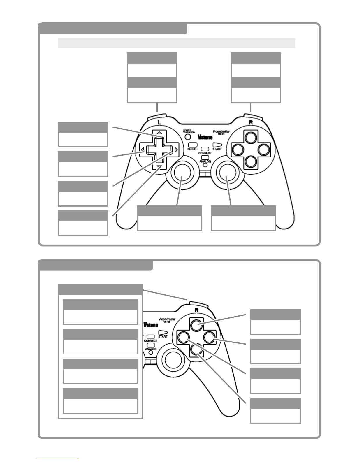
●
▲
×
■
Hello
Ye s
Self Intro
No Way
Keep Pushing R1
R1+●
R1+▲
R1+×
R1+■
Nice to meet you
Cartwheels right
Cartwheels left
N/A
R2
LEFT
UP
DOWN
RIGHT
Forward
Side step left
Side step right
Backward
Turn right
Turn left
L2
Get up from face down
Get up from face up
R1
Shift button
All direction
L1
L3 R3
3 Always Common Buttons (motions)
These buttons have the same functionality in all default control maps
3 Primary Modes SELECT + ▲
Page 88
87
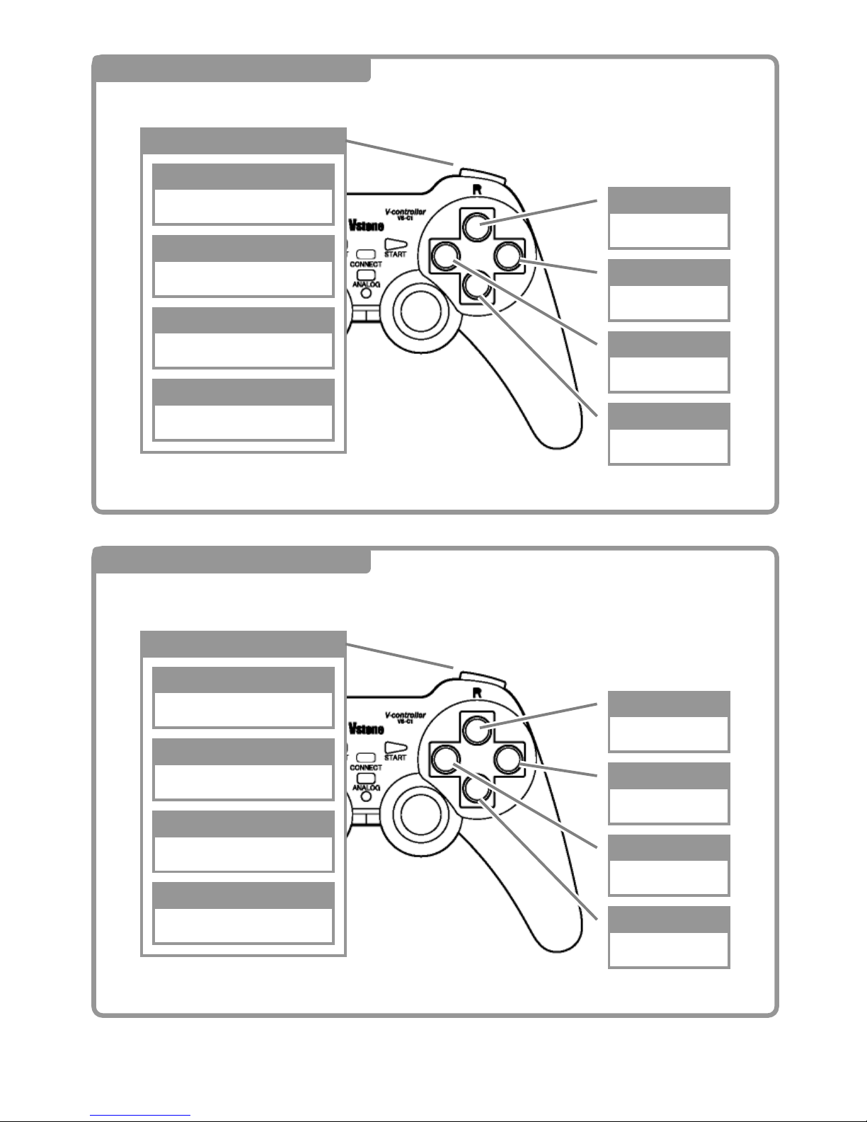
●
▲
×
■
Front Punch
Right Punch
Left Punch
Defend
While Holding R1 Button
R1+●
R1+▲
R1+×
R1+■
Punch
Punch(right)
Punch(left)
Defend
4 Soccer SELECT + ●
●
▲
×
■
Forward little
Shoot right
Shoot left
N/A
While pushing R1 button
R1+●
R1+▲
R1+×
R1+■
Walk forward slightly
Keeper save right
Keeper save left
Keeper save middle
5 Battle Mode SELECT + ■
 Loading...