

VSS Nederland VCD-5371PIX User Manual
INFORMATION - This equipment has been tested and found to comply with
limits for a Class A digital device, pursuant to part 15 of the FCC Rules & CE Rules.
These limits are designed to provide reasonable protection against harmful
interference when the equipment is operated in a commercial environment.
This equipment generates, uses, and can radiate radio frequency energy and, if
not installed and used in accordance with the instruction manual, may cause
harmful interference to radio communications.
Operation of this equipment in a residential area is likely to cause harmful
interference in which case the user will be required to correct the interference at
his own expense.
◆
Do NOT use power sources other than those specified.
◆
Do NOT expose this appliance to rain or moisture.
This installation should be made by a qualified service person and
should conform to all local codes.
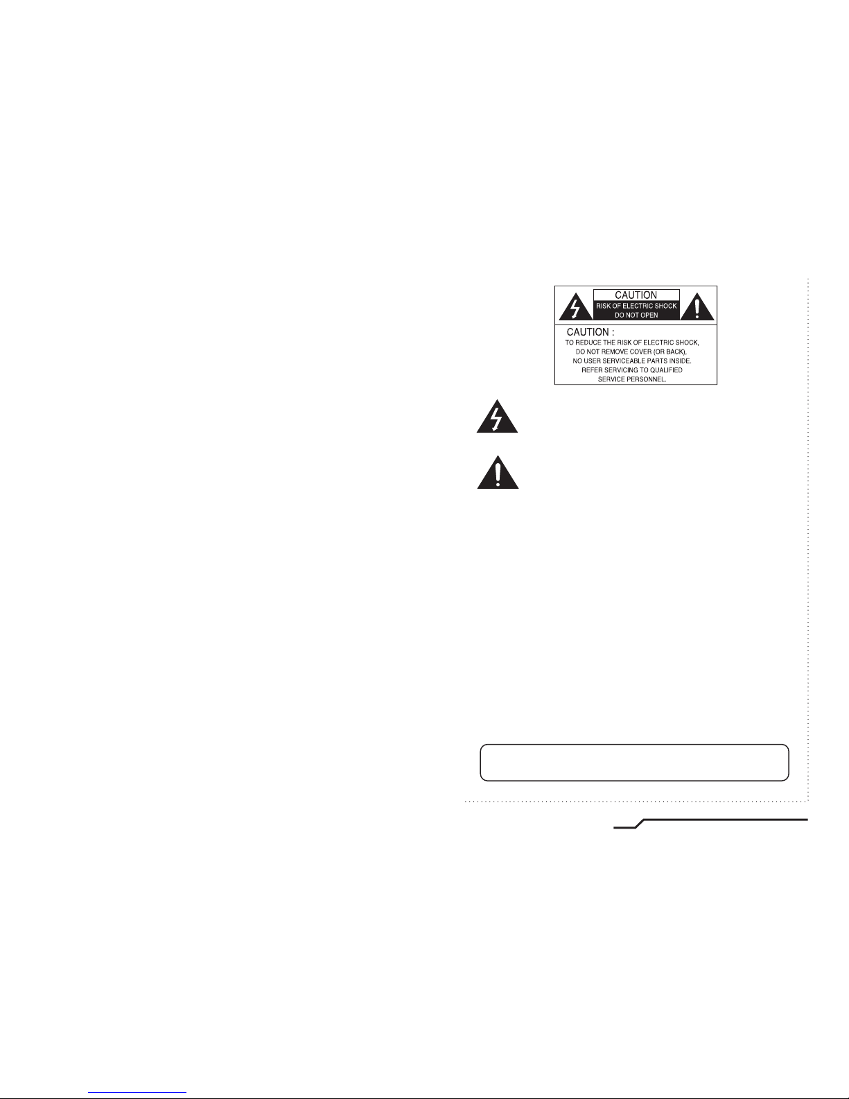
The lightning flash with an arrowhead symbol, within an equilateral
triangle is intended to alert the user to the presence of uninsulated
dangerous voltage within the product's enclosure that may be of
sufficient magnitude to constitute a risk of electric shock to persons.
The exclamation point within an equilateral triangle is intended to alert
the user to the presence of important operating and maintenance
(servicing) instructions in the literature accompanying the appliance.
WARNING - Changes or modifications not expressly approved by the
manufacturer could void the user's authority to operate the equipment.
CAUTION : To prevent electric shock and risk of fire hazards:
1
WDR Digital Sensor Color Dome Camera

2
WDR Digital Sensor Color Dome Camera
3
WDR Digital Sensor Color Dome Camera
How to Use the Camera
15
■ Menu
15
■ Settings
16
ㆍ PRESETS
17
ㆍ EXPOSURE
18
ㆍ WDR
20
ㆍ WHITE BALANCE
21
ㆍ DAY/NIGHT
22
ㆍ IMAGE ADJ.
23
ㆍ SPECIAL
25
- CAMERA ID
- VIDEO OUT
- D-ZOOM
- MOTION
- PRIVACY SETUP
- SYNC
- RS485 SETUP
ㆍ EXIT
29
25
26
27
27
28
29
29
Troubleshooting
30
Specifications
32
■
Contents
Features
Warnings and Precautions
Names and Functions of Parts
Installation
Cable Connection
■ Lens
■ OSD
■ VBS-EXTRA
■ 3 Axis Bracket
4
5
9
Dimensions
11
12
Installation (Adaptor Plate)
14
12
10
10
11
11
Components
8

4
WDR Digital Sensor Color Dome Camera
5
WDR Digital Sensor Color Dome Camera
Additional Functions
SYNC (INT/LL), SENS-UP, FREEZE, FLIP
(H/V-REV), D-ZOOM, SHARPNESS and
PRIVACY functions are provided.
Controlled by OSD Menu
The camera can be controlled by selecting
text displayed on the monitor screen.
Wide Dynamic Range (WDR)
The camera delivers clear high quality pictures,
even when backlit, by increasing exposure in
dark areas while decreasing it in bright areas;
a corrected image with clear details results.
ㆍ120dB maximum dynamic range
RS-485 Communication
Control Support (optional)
Remote OSD menu control via an RS-485
interface is supported.
■
Features
Warning ■
The camera requires periodic inspection.
Contact an authorised technician to carry out the inspection.
Stop using your camera when you find it malfunctioning.
If the camera emits smoke or is unusually hot for a long period,
a fire may be caused.
Do not Install the camera on a surface that can not support it.
If the camera is installed on an inappropriate surface, it may fall
and cause injury.
Do not hold plug with wet hands.
It could cause an electric shock.
Do not dis-assemble the camera.
It may result in an electric shock or other hazards.
Do not use the camera close to a gas or oil leak.
It may result in a fire or other hazards.
Motion Detection
Since the camera detects motion without any
additional external sensor, you can monitor
activity more efficient.
Programmable GAMMA Processing
3 Axis built-in 100mm Dome Housing
High Resolution Color for Crisp,
Clear Video
ㆍProgressive image capture
ㆍ690TVL Effective
Day & Night
The camera identifies whether it is day or night
and automatically switches to the appropriate
mode, depending on its environment. By day,
the camera switches to color mode in order to
maintain optimal color. At night, it switches to
B/W mode so as to obtain better picture definition.
High Sensitivity for low-light
images
The built-in high sensitivity
PIXIM SEAWOLF Sensor enables
a clear image even at 0.1Lux
DNR (Digital Noise Reduction)
The amount of low illuminance noise has been
significantly reduced, and the signal-to-noise
ratio (S/N ratio) as well as horizontal resolution,
have been improved resulting in a clear and
sharp image image even in low light.
6
WDR Digital Sensor Color Dome Camera
7
WDR Digital Sensor Color Dome Camera
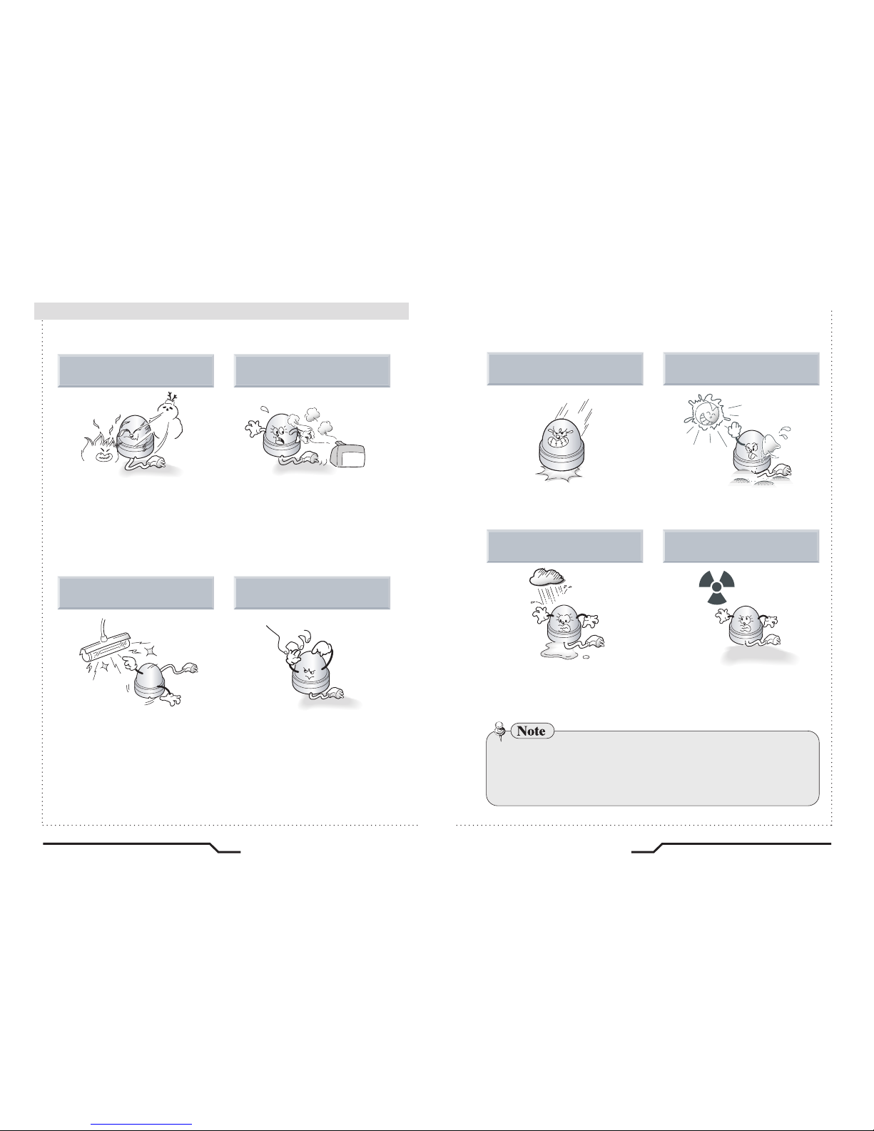
■
Precautions
Do not install the camera in
extreme temperature conditions.
Do not install the camera under
unstable lighting conditions.
Do not touch the front lens of the
camera.
Only use the camera under conditions
where temperatures are between
-10˚C and +50˚C. Be especially
careful to provide ventilation when
operating under high temperatures.
It can cause the image quality to be
poor.
Severe lighting change or flicker can
cause the camera to work improperly.
This is one of the most important parts
of the camera. Be careful not to leave
fingerprints on the lens cover.
Do not install or use the camera in an
environment where the humidity is high.
It can cause malfunctions to occur.
If it gets wet, wipe it dry immediately.
Liquids can contain minerals that
corrode the electronic components.
If exposed to radioactivity the CCD
will fail.
It can damage the CCD.
Do not drop the camera or protect
it from physical shocks.
Do not expose the camera to rain
or spill beverage on it.
Do not expose the camera to
radioactivity.
Never keep the camera pointed
directly at strong light.
ㆍIf the camera is exposed to spotlight or an object reflecting strong light,
smear or blooming may occur.
ㆍPlease check the power supply satisfies the normal specification before
connecting the camera.
8
WDR Digital Sensor Color Dome Camera
9
WDR Digital Sensor Color Dome Camera
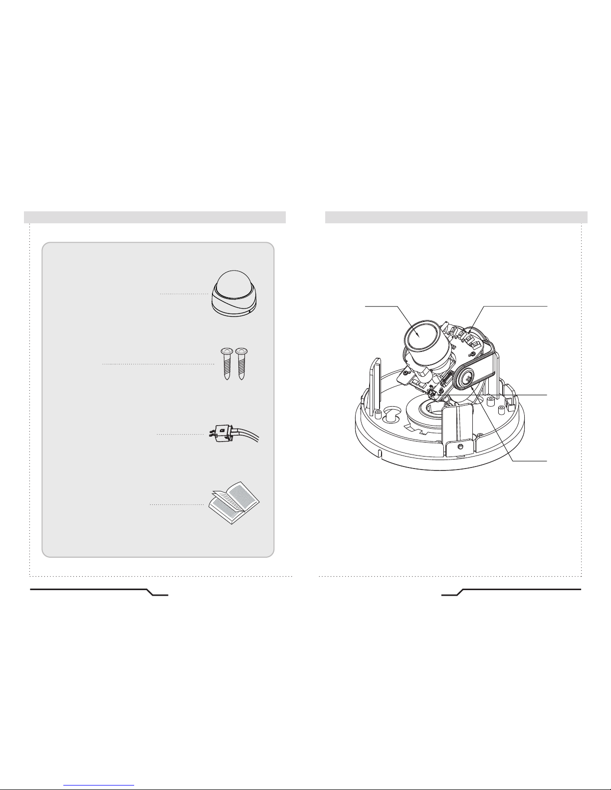
■
Components
Names and Functions of Parts
■
1. COLOR DOME CAMERA
2. SCREWS
3. WIRE FOR VBS-EXTRA
4. INSTRUCTION GUIDE
③
④
②①
10
WDR Digital Sensor Color Dome Camera
11
WDR Digital Sensor Color Dome Camera
■
Names and Functions of Parts
Names and Functions of Parts
■
②
OSD PCB
●
SET button : Used for the menu display. This button can be used to
confirm settings after changing the value of the selected function or
current conditions.
●
UP & DOWN buttons : Used for selecting items by moving the cursor
up or down on the menu screen.
●
LEFT & RIGHT buttons : Used when changing item values, by moving
the cursor to the left or right on the menu screen.
①
LENS : Vari-Focal DC Auto Iris Lens
DOWNUPSETRIGHTLEFT
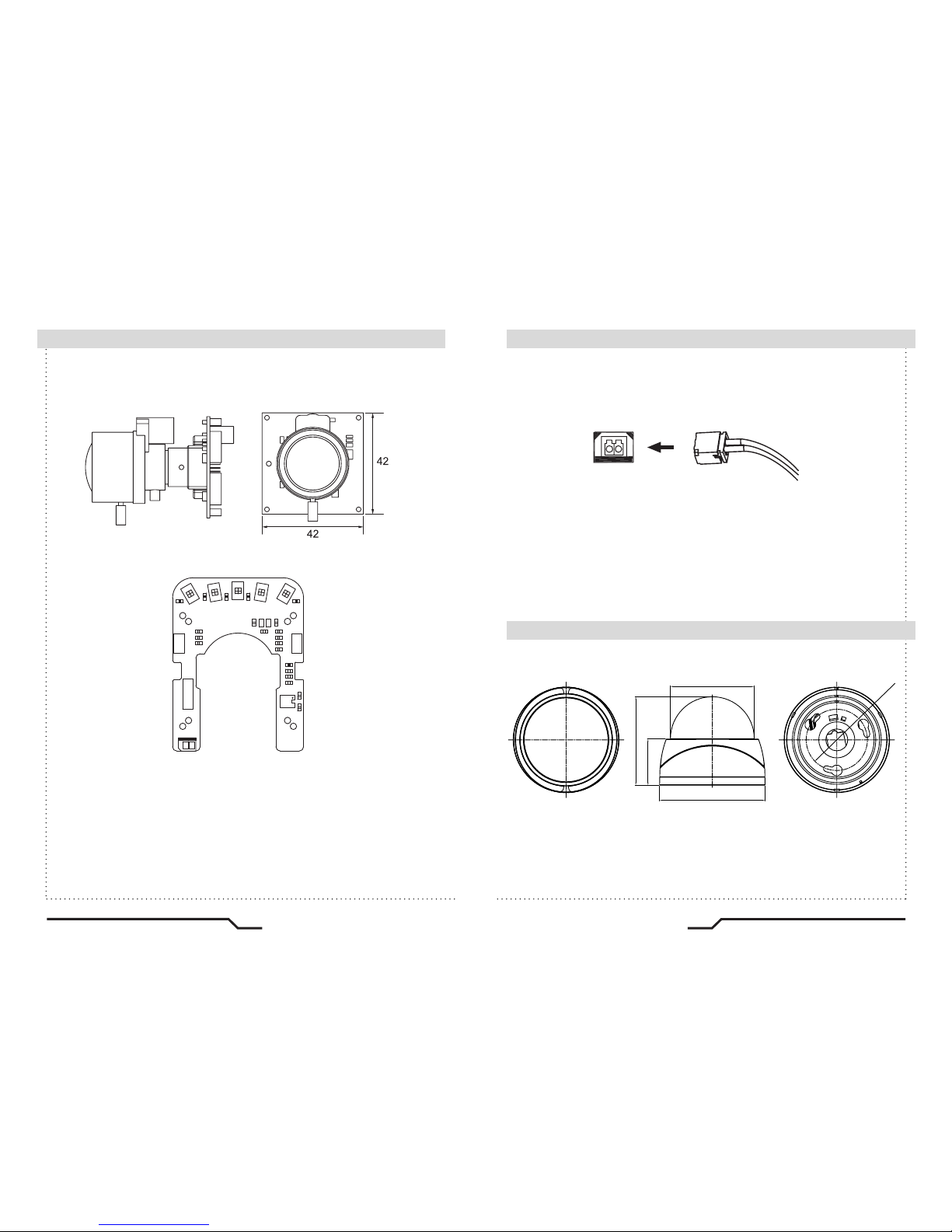
③
VBS-EXTRA FOR CONNECTING TO LCD
Please use the supplied wire when connecting to external monitor
VBS-EXTRA
④
3 AXIS BRACKET
Adjust the pan and tilt to give the correct angle of view.
(unit : mm)
100
φ
73.0
φ
125.79
φ
105.5
55.0
Dimensions
■
 Loading...