

VSI 1000-X Series, SF-LB Quick Setup Manual
SF-LB QUICK SETUP GUIDE
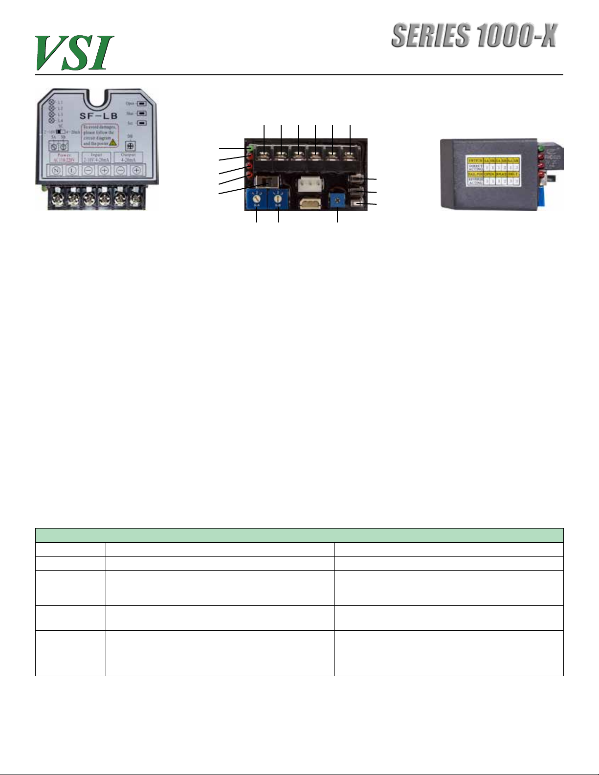
FEED
POWER CTRL
LED 1
LED 2
LED 3
LED 4
SC
FIGURE A FIGURE B FIGURE C
SA SB DB
BACK
++ + -- -
OPEN
SHUT
SET
The SF-LB control pack, if shipped together with a Series 1000-X actuator, is factory calibrated and
set for 90° rotation and no adjustment should be needed. However, if you are replacing the SF-LB
or the factory settings do not conform to your actuator/valve application, some adjustment may be
necessary.
INITIAL SETUP
If the SF-LB is not installed – install in the actuator by plugging in the two cables into the unit. Connect the appropriate power to terminals 1&2. Connect the control signal to terminals 3&4 and note
that the polarity must be positive and negative.
If feedback is being used connect the wiring to terminals 5&6. The SF-LB provides position feedback
of 4-20mA.
At this point the Green LED “L1” should be illuminated. If red LED “L2” is illuminated then the control
signal is faulty or SC is not set correctly for your control signal. Ensure that SC is set for your application control signal (2-10V or 4-20mA). See the chart below for failure mode conditions on the SF-LB
control pack. Your actuator should be ready to operate.
SF-LB CONTROL PACK LED’S
LED CAUSE DESCRIPTION REMEDY
LED-1 (GREEN) POWER IS PRESENT ON INPUT TERMINALS ALL IS NORMAL - NONE NEEDED
LED-2 (RED) CONTROL SIGNAL IS WRONG OR NOT PRESENT CHECK SC SWITCH TO ENSURE PROPER CONTROL
SIGNAL IS SELECTED - CHECK TO ENSURE SIGNAL IS
PRESENT
LED-3 (RED) POTENTIOMETER IS NOT CALIBRATED WITH ACTUATOR
OUTPUT
LED-4 (RED) OVERTORQUE CONDITION PRESENT - VALVE BINDING,
OR MANUAL OVERRIDE HAS BEEN USED AND
ACTUATOR IS OUT OF SYNC WITH CONTROLLER
NOTE: THE ACTUATOR WILL NOT OPERATE WHEN MANUAL OVERRIDE PUSH BUTTON IS DEPRESSED
RE-CALIBRATE POTENTIOMETER PROCEDURE IN IOM
(CALL FOR ASSISTANCE)
CHECK TO MAKE SURE VALVE IS NOT BINDING. RESET
CONTROL PACK BY ROTATING S-A FROM 1 TO 2 AND
BACK TO 1, or REMOVE POWER TO THE ACTUATOR AND
REPLACE

SF-LB QUICK SETUP GUIDE
FIGURE D
MANUAL OVERRIDE PUSH BUTTON
The Series 1000-X units are equipped with a manual override power button which disconnects
the power to the actuator motor so that the unit can be rotated using the provided hand crank or
the optional hand wheel. Although SF-LB LED’s are operating, the motor power is disconnected
internally. If manual operation of unit is performed, the unit will need to be re-set by switching SA
from 1 to 2 and back to 1 again.
SWITCH SETTINGS
SA is used for setting the “direct acting” (2V=closed and 10V=open) or “reverse acting “(2V=open and
10V=closed) rotation of the actuator. SA is also used for placing the actuator in “set mode”. Set mode
is used to stroke the actuator using the “open” and “shut” buttons and used for setting the stoke limit
position of the actuator. SB is used for setting the positioning of the actuator in the case of a control
signal loss. Figure C shows the side of the controller with the options using SA and SB. Actuators
are shipped with the SF-LB control packs set to “direct acting” and fail “in place”. SC is used for
selecting the control signal (2-10V or 4-20mA). DB is used for setting the sensitivity on the “dead
band” – rotate clockwise for less sensitive, rotate CCW for more sensitive. Units are set to mid-range
sensitivity from factory.
SETTING THE POSITION LIMITS
NOTE: ACTUATOR IS EQUIPPED WITH MECHANICAL STOPS. THESE ARE FOR SAFETY ONLY AND
SHOULD NOT BE USED TO SET THE POSITION LIMITS ON THE ACTUATOR.
Position limits are factory set to 90° rotation. If desired, the position limits can be re-configured to
rotate less than 90°. To re-set the position limits of the unit, SA should be placed in “set mode”
by switching to “2”. At this point, the open and shut buttons can be used to stroke the actuator to
the desired position. To set the closed limit, make sure the control signal is applied with the proper
setting. For example – 2V is need for closed. Rotate the valve to the closed position. While holding
the white “set button” also press the “shut” (middle) button and hold until the LED flashes – then
release both buttons. This sets the closed limit. To set the open limit, rotate the actuator to the
open position using the “open” (top) push button. Place 10V control signal on input. While holding
the white “set button”, press and hold the “open” button until the LED flashes – then release both
buttons. This sets the open limit. Finally, switch SA back to 1 or 3 depending on the operation of the
unit (1 is direct acting and 3 is reverse acting).
For the complete IOM on the Series 1000-X actuators, please visit www.valvesolutions.com or if
technical support is needed during setup or troubleshooting, please call 770-740-0800.
 Loading...