

Page 1

PWM SERIES
STATIC DIGITAL
AC AUTOMATIC VOLTAGE STABILISER
USER MANUAL
Thank you for purchasing a VSi PWM Series
Static Digital AC Automatic Voltage Stabiliser
Page 2

Page
1
IMPORTANT
PLEASE READ
This User / Operator Manual contains information concerning the safe and
proper installation and operating procedures applicable to the PWM range of
Single Phase Static Digital AC Automatic Voltage Stabilisers.
The Manual should be read in full before attempting to use, or operate the
equipment.
If any problems are encountered with the procedures contained within this
Manual then seek assistance from VSi or the distributor from whom you
purchased the equipment.
Whilst every precaution has been taken to ensure the accuracy and completeness
of this User Manual, VSi assumes no responsibility and disclaims all liabilities for
damages resulting from misuse of this information or any error or omission.
Voltage Stabilisers International Limited
Tel: +44 (0) 345 504 6324
Web: http://www.VSi.uk.com
Email
PWM SERIES - User Manual
VSi-PWM-2018-06
http://www.VSi.UK.com
Page 3

Page
2
Table of Contents
1.1
Overview
…………………………………………………………………
……………..
3
1.2
Basic Principle of Op
eration
……………………………………
……………..
3
2.1
Input
………………………………………………………………………………………
4
2.2
Output
……………………………………………………………………………………
4
2.3
Metering, Status Indicators, Alarms & Communication
………….
5
2.4Protection
………………………………………………………………………………
5
2.5
Environment
…………………………………………………………………………..
6
2.6
Physical
………………………………………………………………………………….
6
2.7
Certification & Compliance
…………………………………………………….
6
2.8
Warranty
………………………………………………………………………………..
7
3.1
Introduction
…………………………………………………………………………..
8
3.2
General Installation and Usag
e
………………………………………………
8
4.1
Front View
…………………………………………………
……………………………
10
4.2
Rear View
……………………………………………………………………………….
1
2
4.3
Display View
…………………………………………………………………………..
1
5
5.1
Unpacking & Inspection
………………………………………………………...
185.2
Positionin
g
……………………………………………………………………………..
1
8
5.3
Hardwire Installation
……………………………………………………………..
1
9
5.4
Plug N Play Installation
…………………………………………………………..
20
5.5
Normal Operation
………………………………………………………………….
21
5.6
Manual Bypass Operation
……………………………………………………
…22
7.1
Warranty
………………………………………………………………………………..
2
7
7.2
Returns Procedure
…………………………………………………………………
2
8
Pages
1. Introduction ………………………………………………………………………. 3
2. General Specification ………………………………………………………… 4-7
3. Safety Instructions …………………………………………………………….. 8-9
4. Visual External Appearance ………………………………………………. 10-17
5. Installation & Operating Instructions ………………………………… 18-22
6. Troubleshooting ………………………………………………………………… 23-26
7. Warranty & Returns …………………………………………………………… 27-28
PWM SERIES - User Manual
VSi-PWM-2018-06
http://www.VSi.UK.com
Page 4
Page
3
1. Introduction
1.1 Overview
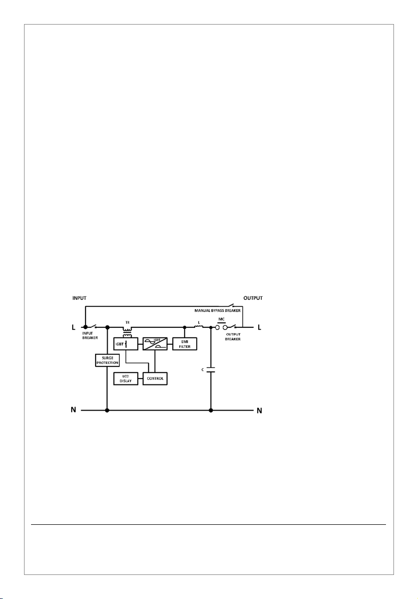
PWM SERIESmicroprocessor controlled Single Phase Static Digital Voltage
Stabilisers automatically correct brownouts (by boosting low voltage)
and over-voltages (by reducing high voltage). They are, designed to
ensure the delivery of a stable and quality output voltage.
Being designed for many years of reliable service, VSi’s PWM models
provide protection from incoming line voltage sags, spikes and surges /
swells. As Static Digital solutions they are virtually maintenance free and
offer an exceptional fast speed of correction, making them ideal for the
most sensitive of electrical and electronic loads.
1.2 Basic Principle of Operation
PWM SERIES AC Voltage Stabilisers are designed around a traditional well
proven ‘Buck / Boost’ design topology, utilising the latest in IGBT Power
Devices and digital PWM (Pulse Width Modulated) controls.
Please Note: PWM Voltage Stabilisers are NOT FOR USE with life
sustaining equipment, or any device where the power requirements
exceed the “Maximum Output Rating” listed in the General Specification
tables. These Stabilisers are not designed to support / protect voltage
“back feed” applications, where energy is required to be also fed back
into the utility supply.
PWM SERIES - User Manual
VSi-PWM-2018-06
http://www.VSi.UK.com
Page 5
Page
4
2. General Specification
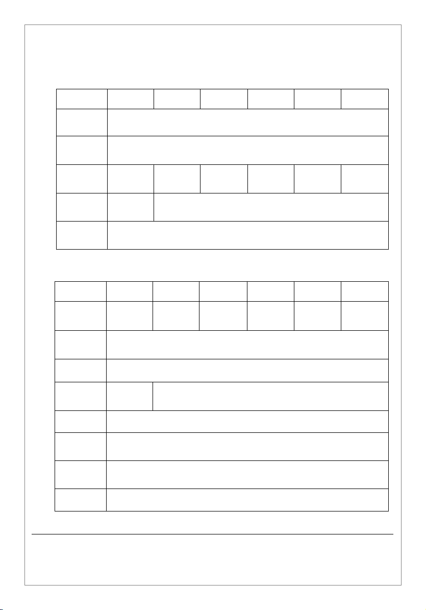
2.1 Input
Model No
Input
Voltages
PWM
2.1H-S25
PWM
3.5H-S25
220V - 230V - 240V AC Single Phase, 2 Wire (L, N & G/E)
PWM
5.25H-S25
PWM
7H-S25
PWM
10.5H-S25
PWM
14H-S25
Voltage
Range
Max Input
Current
Input
Connectors
Operating
Frequency
13 Amps 21 Amps 32 Amps 42 Amps 63 Amps 84 Amps
IEC 320
(16 Amp)
230V ±25% (173V to 287V) AC Single Phase, 2 Wire (L, N & G/E)
(220V & 240V to Special Order)
Hardwire
50 / 60 Hz
2.2 Output
Model No
Max Output
Rating
Output
Voltage
Waveform
Output
Connectors
Harmonics <3% of THD for Linear Load
PWM
2.1H-S25
2.1
kVA/kW
2 x IEC320
(10 Amp)
PWM
3.5H-S25
3.5
kVA/kW
230V ±1%, Single Phase, 2 Wire (L, N & G/E)
PWM
5.25H-S25
5.5
kVA/kW
(220V & 240V to Special Order)
Sine Wave
Hardwire
PWM
7H-S25
7.0
kVA/kW
PWM
10.5H-S25
10.5
kVA/kW
PWM
14H-S25
14.0
kVA/Kw
Speed of
Correction
Power
Factor
Frequency 50 / 60 Hz (what goes in comes out)
PWM SERIES - User Manual
VSi-PWM-2018-06
http://www.VSi.UK.com
Ultra-Fast – Within 200 milliseconds
(0.2 Seconds)
No effect on performance providing the Stabiliser
is being used within its rated capacity
Page 6
Page
5
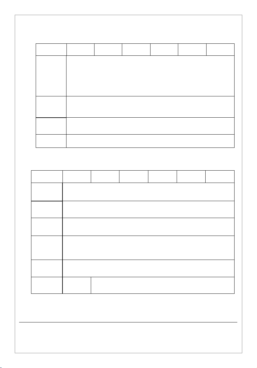
2.3 Metering, Status Indicators, Alarms & Communication
Model No
Digital
Metering
Status
Indicators
Audib le
Alarms
Comms RS-232
PWM
2.1H-S25
PWM
3.5H-S25
PWM
5.25H-S25
Input & Output Volts (V)
Input & Output Frequency (Hz)
Internal Temperature (°c)
Load Current (Amps)
Load Level Indicator (%)
Line, Normal, Bypass & Fault
Fault & Over Voltage
PWM
7H-S25
PWM
10.5H-S25
2.4 Protection
Model No
Over
Current
Overload More than 105% Output Automatically Disconnected – requiring Manual Restart
Under & Over
Voltage
Over
Voltage
Surge
Protection
Noise
Protection
PWM
2.1H-S25
PWM
3.5H-S25
Input & Output Breakers – as Standard
Automatic Disconnect requiring Manual Restart
(Output Under Limit 188V ±4V / Over Limit 270V ±4V)
PWM
5.25H-S25
MOV (Varistor)
EMI Filter
PWM
7H-S25
PWM
10.5H-S25
PWM
14H-S25
PWM
14H-S25
Man ual
Byp ass
NO YES – inbuilt as Standard
PWM SERIES - User Manual
VSi-PWM-2018-06
http://www.VSi.UK.com
Page 7
Page
6
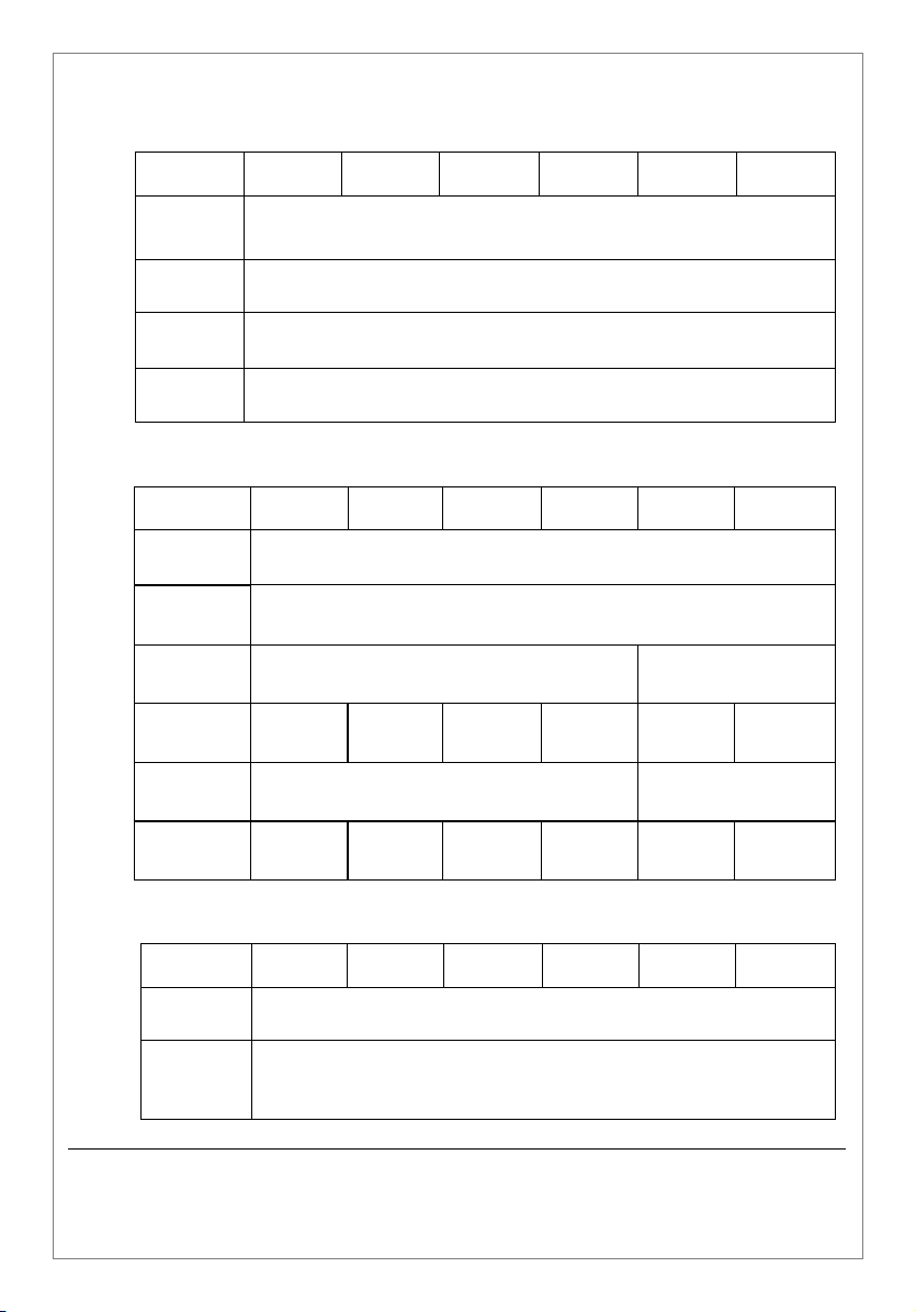
2.5 Environment
Model No
Operating
Temp
Range
Maximum
Altitude
Relative
Humidity
Audible
Noise
PWM
2.1H-S25
PWM
3.5H-S25
Derate by 2% for each additional ºc up to a max. of 60 ºc
Derate by 1% for each additional 100 metres
Suitable for indoor use up to 90% Relative Humidity
PWM
5.25H-S25
0 to 40ºc
2000 metres
(non-condensing).
<50 dBA (@1 Metre)
PWM
7H-S25
PWM
10.5H-S25
2.6 Physical
Model No
Construction Freestanding Enclosures to IP20 (NEMA 1 Style) - BS/EN 60529
Colour RAL 7047 (Telegray 4)
Physical Size 258(W) x 333(H) x 422(D) mm
Weight 23 Kg 29 Kg 30 Kg 32 Kg 58 Kg 62 Kg
Packed Size 38.1 (W) x 44.5(H) x 54(D) cm
PWM
2.1H-S25
PWM
3.5H-S25
PWM
5.25H-S25
PWM
7H-S25
PWM
10.5H-S25
258 (W) x 546(H) x
40.2 (W) x 78(H) x
PWM
14H-S25
PWM
14H-S25
532(D) mm
68(D) cm
Packed
Weight
25.5 Kg 31.5 Kg 32.5 Kg 34.5 Kg 68.5 Kg 72.5 Kg
2.7 Certification & Compliance
Model No
EMC
Compliance
CE
Certification
PWM
2.1H-S25
CE Marked – being fully compliant with European Union Directives
PWM SERIES - User Manual
VSi-PWM-2018-06
http://www.VSi.UK.com
PWM
3.5H-S25
Complies with BS/EN 55022 & the relevant part of
2014/35/EU (The Low Voltage Directive)
PWM
5.25H-S25
BS/EN 61000 Standards
2014/30/EU (The EMC Directive) and
PWM
7H-S25
10.5H-S25
PWM
PWM
14H-S25
Page 8
Page
7
2.8 Warranty
Model No
Standard
Warranty
PWM
2.1H-S25
PWM
3.5H-S25
PWM
5.25H-S25
24 Months / 2 Years
PWM
7H-S25
PWM
10.5H-S25
PWM
14H-S25
PWM SERIES - User Manual
VSi-PWM-2018-06
http://www.VSi.UK.com
Page 9

Page
8
3. Safety Instructions
Read and follow all Safety Instructions
Please save these instructions for future reference
3.1 Introduction
These instructions are addressed to the installer and End User / Operator
of the PWM SERIES of Single Phase Static Digital AC Voltage Stabilisers. We
strongly suggest you keep this manual next to the equipment for future
reference.
3.2 General Installation & Usage
Do not use the Stabiliser for other than the intended use.
Do not install Stabiliser in back feed circuits, such as solar panel and wind
turbine applications, where the energy is supplied back to the grid, nor
should the input voltage supply be connected to the output of stabiliser.
If on delivery there is evidence of visible damage, do not attempt to install
or start the Stabiliser. Advise the transport delivery company and inform
VSi, or the resale partner from whom you purchased the equipment.
The Stabiliser can contain potentially dangerous voltages – up to 300V AC.
As there are no user replaceable components, once installed there should
be no reason to remove the protective covers. If the covers are removed,
use extreme caution and do not leave the unit unattended with the covers
off.
Hazardous voltages can be present at the unit’s output any time AC input
power is applied. To avoid possible personal injury, or equipment
damage, and to make certain there is no output voltage, turn the unit off
and disconnect the AC Input.
To reduce the risk of fire, or electrical shock, install the unit in an indoor
area free from conductive contaminants.
PWM SERIES - User Manual
VSi-PWM-2018-06
http://www.VSi.UK.com
Page 10

Page
9
Do not use outdoors.
Do not place the unit near water or liquids, gas and combustible materials
or in an excessively humid environment where condensation is very likely
to occur.
To reduce the risk of overheating, do not block the unit’s ventilation
panels and try to avoid positioning the unit in direct strong sunlight or
close to other heat sources.
Do not allow liquids or foreign object to enter the unit.
The installation and use of this product must comply with all relevant
current electrical installations that are in force in the territory of
installation.
Where the system is required to be hardwired into the input utility mains
supply we would strongly suggest that a qualified electrician should install
the equipment. The electrician should install the AC input accordingly to
the instructions contained in this manual. Standard safety practices
should be followed at all times.
The unit must be grounded / earthed at all times when in use.
PWM SERIES - User Manual
VSi-PWM-2018-06
http://www.VSi.UK.com
Page 11
Page
10
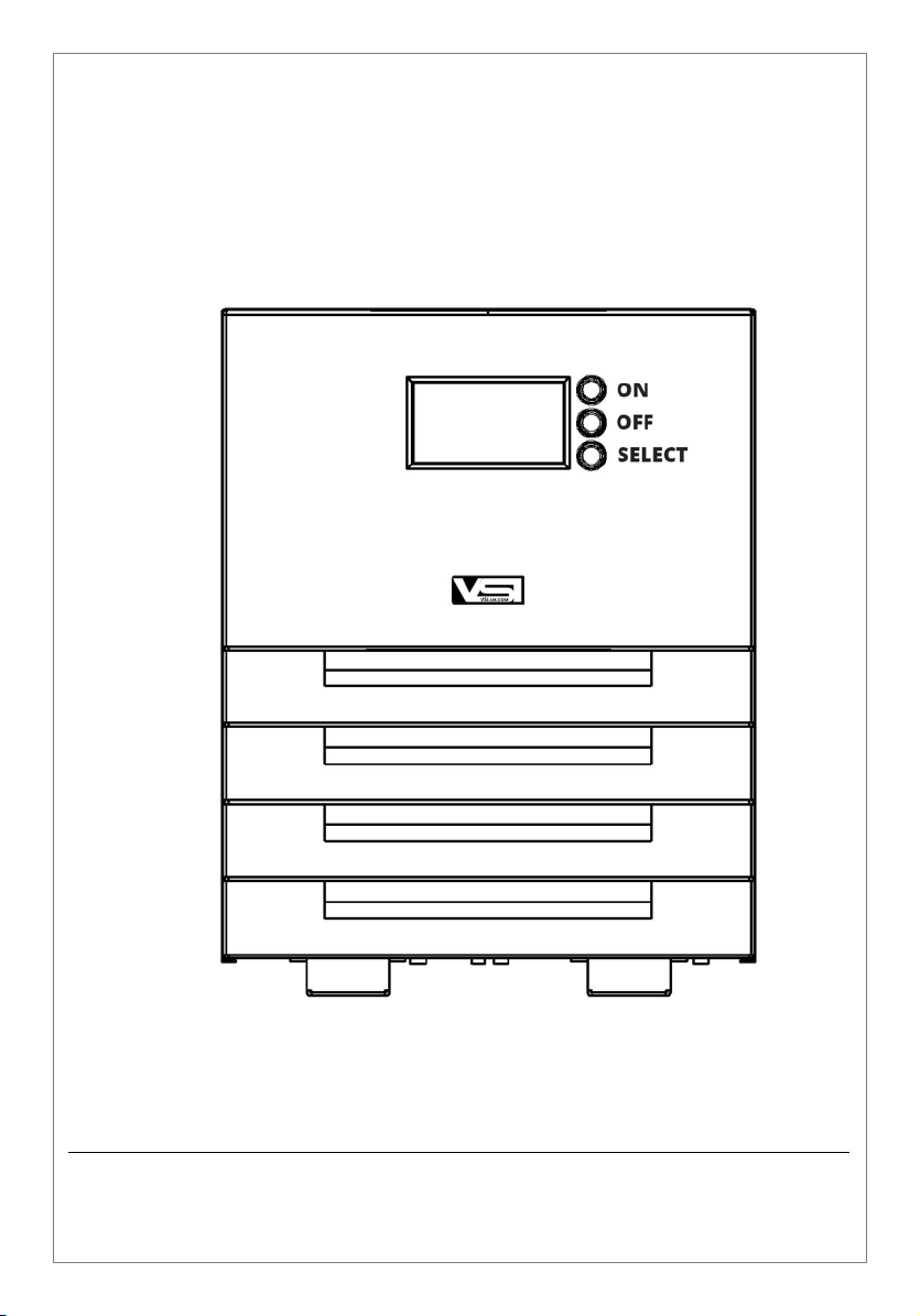
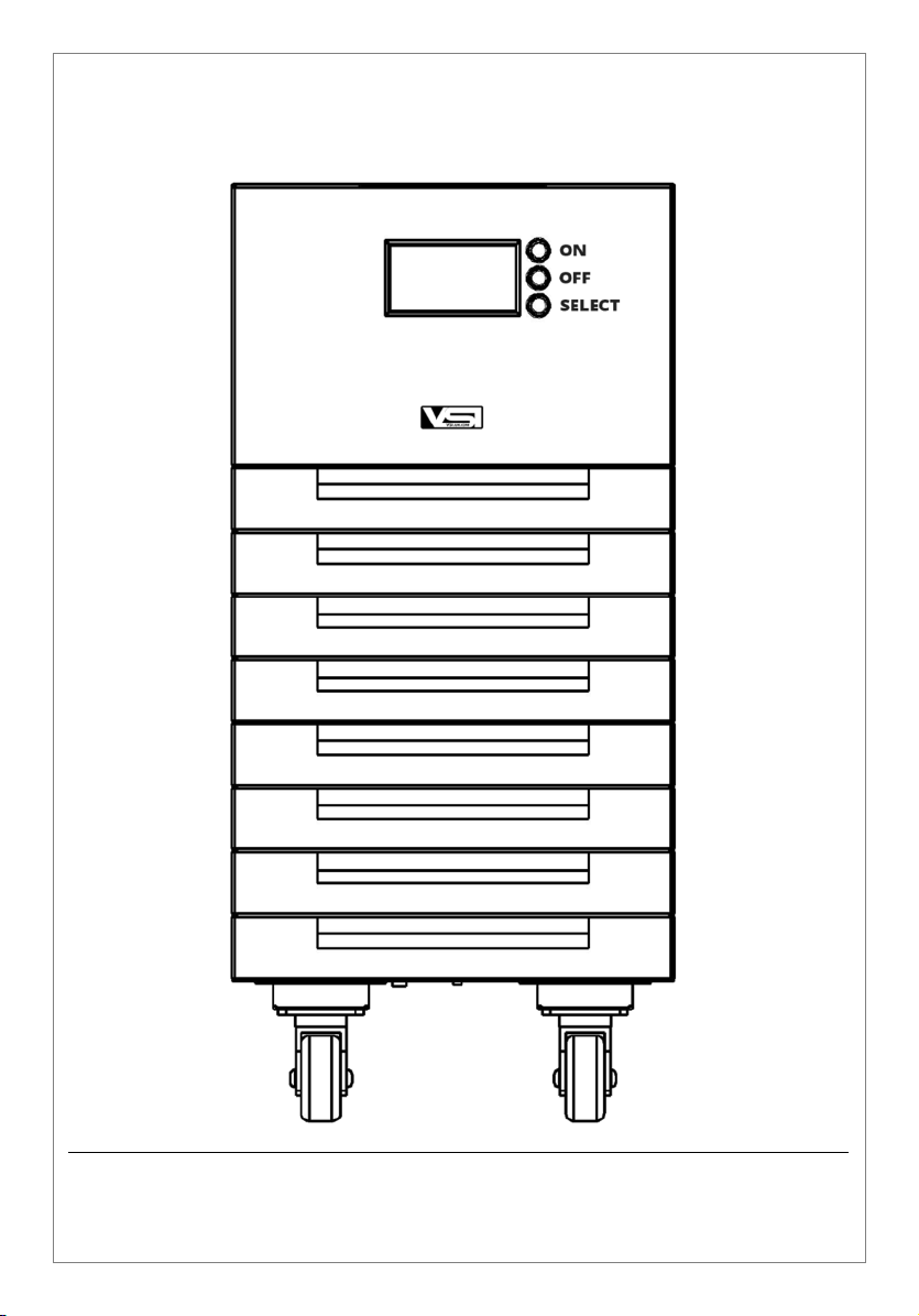
4. Visual External Appearance
4.1 Front View
4.1.1 Model: PWM-2.1H-S25 to PWM-7H-S25
PWM SERIES - User Manual
VSi-PWM-2018-06
http://www.VSi.UK.com
Page 12
Page
11
4.1.2 Model: PWM-10.5H-S25 to PWM-14H-S25
PWM SERIES - User Manual
VSi-PWM-2018-06
http://www.VSi.UK.com
Page 13

Page
12
4.2 Rear View
4.2.1 Model: PWM-2.1H-S25
PWM SERIES - User Manual
VSi-PWM-2018-06
http://www.VSi.UK.com
Page 14

Page
13
4.2.2 Model PWM-3.5H-S25 – PWM-7H-S25
PWM SERIES - User Manual
VSi-PWM-2018-06
http://www.VSi.UK.com
Page 15

Page
14
4.2.3 Model PWM-10.5H-S25 – PWM-14H-S25 (on Castors)
PWM SERIES - User Manual
VSi-PWM-2018-06
http://www.VSi.UK.com
Page 16

Page
15
4.3 Front Display Panel
In normal running mode both the ‘LINE’ and ‘INV’ Status Indicators should
be illuminated.
4.3.1 Status Indicators
All Okay – in line mode
In Bypass Mode
Stable Output Voltage
Output Overload or an Abnormal Condition
exists
PWM SERIES - User Manual
VSi-PWM-2018-06
http://www.VSi.UK.com
Page 17

Page
16
4.3.2 Digital Metering
Press and hold down the ‘SELECT’ Control Button for 1.5 seconds
to change the displayed reading.
Holding down the ‘SELECT’ Control Button will enable an
automatic rotation of the available readings.
Releasing the ‘SELECT’ Control Button will stop the rotation at the
required reading.
Available Readings are
Input Voltage
(I/P Vac)
Output Voltage
(O/P Vac)
Input Frequency
(I/P Hz)
Output Frequency
(O/P Hz)
Load Current
(O/P)
Temperature
(ºC)
Voltage level of the incoming
utility mains supply
Output Voltage delivered by
the system.
Frequency of the incoming
utility mains supply
Output Frequency delivered
by the system.
Power (Amps) drawn by the
connected load.
Internal Temperature of the
system
Please Note: The multifunctional display is for indication
purposes only and may not display the exact voltage and current
readings as seen by a calibrated multi-meter, but should be
within an accuracy of ±5%.
PWM SERIES - User Manual
VSi-PWM-2018-06
http://www.VSi.UK.com
Page 18
Page
17
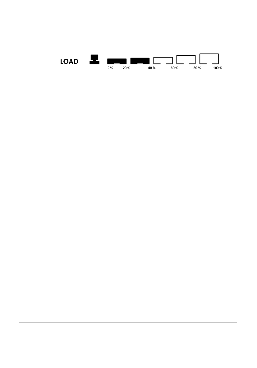
4.3.3 Load Level Indication
In addition to load current readings the display panel also shows
below the digital metering in the form of a bar graph percentage
load readings.
PWM SERIES - User Manual
VSi-PWM-2018-06
http://www.VSi.UK.com
Page 19

Page
18
5. Installation & Operation Instructions
5.1 Unpacking & inspection
If on delivery there is evidence of visible damage, do not attempt to
install or start the Stabiliser. Advise the transport delivery company and
inform VSi, or the resale partner from whom you purchased the
equipment.
After unpacking and removing the polystyrene protective packaging
from the PWM SERIES unit, inspect the ventilation slots to ensure that
they are free from all obstruction. Use a vacuum cleaner to dislodge any
obstructions.
We would suggest you retain the packing carton and packaging material
to return the PWM SERIES Stabiliser in the unlikely event of its
operational failure.
5.2 Positioning
Although the Stabiliser does not produce excessive heat, you should
ensure that it is positioned so that a free flow of air allows the unit to
cool. To reduce the risk of overheating, do not block the unit’s ventilation
panels and try to avoid positioning the unit in direct strong sunlight or
close to other heat sources.
The Stabiliser is intended for indoor use only. Do not install inside a
closed cupboard and do not allow papers, or other materials, to be piled
on top of the enclosure.
Do not place the unit near water or liquids, gas and combustible
materials or in an excessively humid environment where condensation
is very likely to occur.
PWM SERIES - User Manual
VSi-PWM-2018-06
http://www.VSi.UK.com
Page 20
Page
19
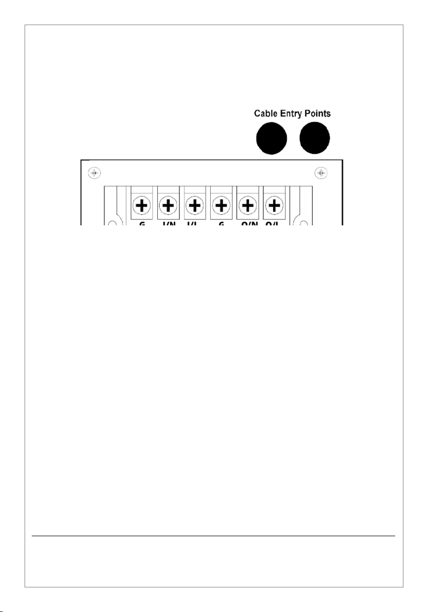
5.3 Hardwire Installation
Models PCM-3.5H-S25 to PCM-14H-S25
Remove Terminals Connection Cover Plate.
Ensure supply is isolated before making connections.
Connect the Input Cable to the terminal block (as indicated) and take
to mains supply via cable entry access hole in the enclosure.
Connect the Output Cable to the terminal block (as indicated) and
take to the load via the relevant cable access hole in the enclosure.
Check all wires are properly secured (using glanding – as
appropriate), connections are tight and cables are correctly wired
before switching on.
Refit Terminals Connection Cover Plate
PWM SERIES - User Manual
VSi-PWM-2018-06
http://www.VSi.UK.com
Page 21
Page
20
Please Note:
If you are unfamiliar with installing electrical equipment, prior to
installing the Stabiliser, please consult with a qualified electrician.
Also with cable connections –
The wire coloured BROWN must be connected to the terminal
marked ‘L’ for Live
The wire coloured BLUE must be connected to the terminal
marked ‘N’ for Neutral.
The wire coloured YELLOW and GREEN must be connected to
the terminal marked ‘G’ for Earth / Ground.
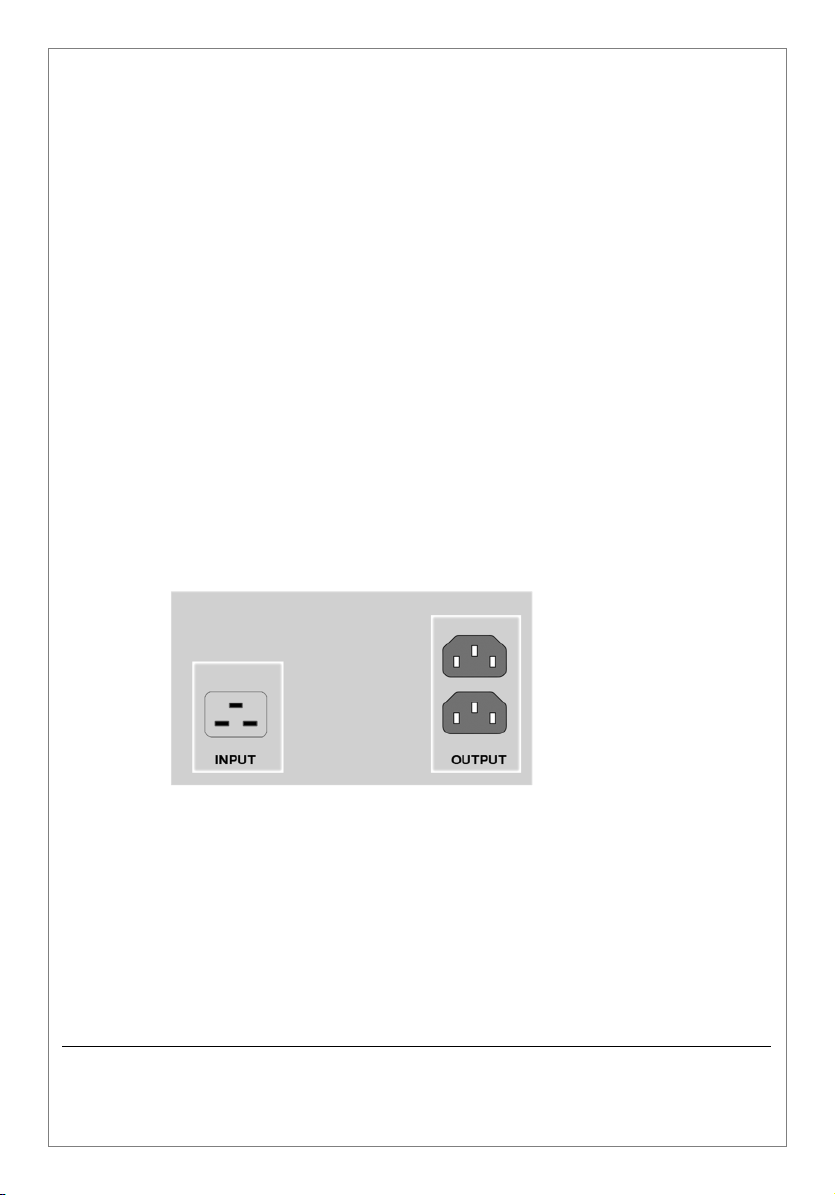
5.4 Plug N Play Installation
Model PCM-2.1H-S25
To ease installation, given the model’s maximum input and
maximum output current ratings, the Voltage Stabiliser is
fitted instead with standard IEC input (16 Amp) and output
sockets (10 Amps).
To install simply utilise a standard 16 Amp IEC Input Cable to
connect the utility mains supply and 10 Amp IEC Output
power cables to connect the load.
PWM SERIES - User Manual
VSi-PWM-2018-06
http://www.VSi.UK.com
Page 22

Page
21
5.5 Normal Operation
5.5.1 Power Up
Without any connected load.
1. Switch CB 1 (Input Breaker) to the ‘ON’ position. Buzzer will
sound for approximately 2.5 seconds while the system runs
through a self-diagnostic testing routine.
Initially the ‘LINE’ Status Indicator on the Front Panel will
illuminate. When the self-diagnostic testing routine has
satisfactorily completed the ‘INV’ Status Indicator will light up.
2. Switch CB 2 (Output Breaker) to the ‘ON’ position.
3. Press the ‘ON’ Button next to the Front Display for 2 seconds.
Front Display will activate.
Stabiliser should now be operational, able to support / have load
connected.
It is recommended that you check the output voltage with a True RMS
Voltmeter to ensure that the correct output voltage is displayed.
If the correct voltage is not measured by the multi-meter please advise
the resale partner / dealer you purchased the stabiliser from, or your
nearest VSi office. Please ensure you advise your support teams of the
model, serial number and where you purchased the stabiliser from.
5.5.2 Power Down
Switch off any connected load.
1. Switch CB 2 (Output Breaker) to the ‘OFF’ position.
2. Press the ‘OFF’ Button next to the Front Display for 2 seconds.
Front Display will deactivate.
While it may appear the stabiliser is fully powered down do not
attempt to remove any side panels from the stabiliser as internally
power will still be present until you complete the next step below.
PWM SERIES - User Manual
VSi-PWM-2018-06
http://www.VSi.UK.com
Page 23

Page
22
3. Switch CB 1 (Input Breaker) to the ‘OFF’ position.
Stabiliser should now be safely powered down.
5.6 Manual Bypass Operation
Only available on models PCM-3.5H-S25 to PCM-14H-S25
Incorrect switching may seriously damage the
Stabiliser /and or connected Load Equipment -
Invalidate any Warranty
5.6.1 Turning On
Please ensue all load equipment is switched off before commencing
any of these procedures.
1. Switch CB 2 (Output Breaker) to the ‘OFF’ position.
2. Switch CB 1 (Input Breaker) to the ‘OFF’ position.
3. Remove the CB 3 (Bypass Switch) Cover Plate.
4. Switch CB 3 (Bypass Switch) to the ON position.
The load is now supplied by the unregulated utility mains supply.
5.6.2 Turning Off
1. Switch CB 3 (Bypass Switch) to the OFF position.
2. Reattach the CB 3 (Bypass Switch) Cover Plate.
Stabiliser should now be ready for Power Up.
PWM SERIES - User Manual
VSi-PWM-2018-06
http://www.VSi.UK.com
Page 24
Page
23
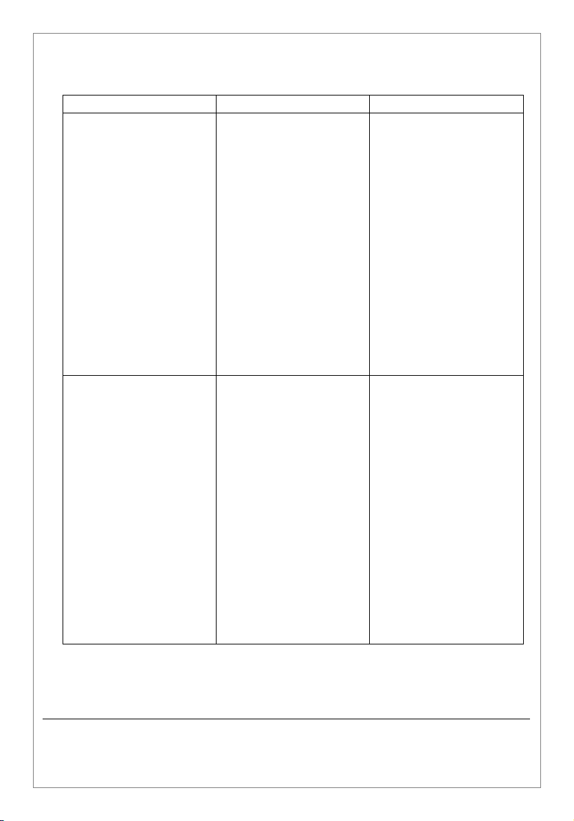
6. Troubleshooting
Symptom Possible Cause Remedy
Display ‘LINE’ indicator is
not illuminated
Display ‘FAULT’ indicator
is illuminated.
1) Extremely irregular
power being is
being supplied
from the utility
mains supply.
1) System is
overloaded.
2) Output Voltage
exceeds ±18.18%.
3) Another Abnormal
Fault condition is
present.
Ensure the level of the
input voltage is within the
permissible input voltage
window of the stabiliser.
Switch off all Breakers
then try re-starting the
Stabiliser by following the
Start-up procedure.
If the ‘LINE’ indicator still
does not illuminate please
seek advice from the
dealer from whom the
stabiliser was purchased,
or get in touch with your
local VSi Support Centre.
Reduce the load.
Restart the Stabiliser.
Follow the power down
sequence, pause and then
try re-starting the
Stabiliser following the
Power up sequence.
If the ‘FAULT’ indicator is
still illuminated please
seek advice from the
dealer from whom the
Stabiliser was purchased,
or get in touch with your
local VSi Support Centre.
PWM SERIES - User Manual
VSi-PWM-2018-06
http://www.VSi.UK.com
Page 25
Page
24
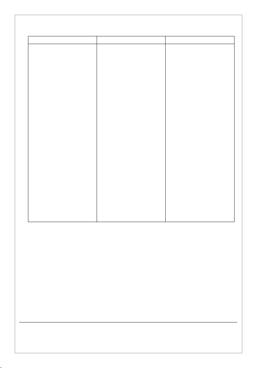
Symptom Possible Cause Remedy
There is no output
voltage
1) The utility mains
supply is not present.
2) CB 2 is switched off.
3) System has
automatically tripped
and requires a
manual restart
Ensure that the input
supply is present.
If present and within the
permissible input voltage
tolerance window, shut
down the Stabiliser as per
the instructions in Section
5.5.2 of this Manual. Wait
10 seconds then restart
following closely the
instructions given in
Section 5.5.1.
If still no output voltage is
present, for models, with
a Manual Bypass, put the
system in Manual Bypass
by following the
instructions given in
Section 5.6 and seek
advice from the dealer
from whom the Stabiliser
was purchased, or get in
touch with your local VSi
Support Centre.
PWM SERIES - User Manual
VSi-PWM-2018-06
http://www.VSi.UK.com
Page 26
Page
25
Symptom Possible Cause Remedy
Display ’INV’ Indicator is
not illuminated.
Display ‘BYPASS’ indicator
is illuminated.
Output Voltage is not
Stable.
1) Input Voltage has
exceeded the
permissible input
voltage window.
2) System is on automatic
Bypass or in Manual
Bypass Mode.
1) Actual load current
exceeds the model’s
stated maximum rating.
Check input voltage and
ensure voltage is within
the permissible window.
Clear the reason for the
system being on
automatic bypass and if
appropriate turn off the
Manual Bypass, following
the instructions given in
Section 5.6.
If the unstable output
voltage condition still
exists, please seek advice
from the dealer from
whom the Stabiliser was
purchased, or get in touch
with your local VSi
Support Centre.
Reduce the loading on the
unit. On overload
clearance the system
should automatically reengaged the inverter to
deliver a stable output
voltage.
If you are unable to clear
the Bypass indicator,
please seek advice from
the dealer from whom the
Stabiliser was purchased,
or get in touch with your
local VSi Support Centre.
PWM SERIES - User Manual
VSi-PWM-2018-06
http://www.VSi.UK.com
Page 27
Page
26
Symptom Possible Cause Remedy
LCD Display is not
operational.
1) Incoming utility mains
supply is not present
and / or CB 1 is not in
the ON position.
Check to ensure mains
supply is present and CB 1
is switched ‘ON’.
If the display is still not
operational, please seek
advice from the dealer
from whom the Stabiliser
was purchased, or get in
touch with your local VSi
Support Centre.
PWM SERIES - User Manual
VSi-PWM-2018-06
http://www.VSi.UK.com
Page 28

Page
27
7. Warranty & Returns
7.1 Warranty
VSi (UK) warrants its products to be free from defect in materials and
workmanship for a period of two (2) years from the date of purchase.
The obligation under this warranty is limited to repairing or replacing, at
VSi’s sole discretion, any such defective products.
The warranty does not apply if the product has been damaged by
accident, negligence, or misapplication or has been altered or modified
in any way.
Except as provided herein, VSi makes no warranties, expressed or
implied, including warranties or merchantability and fitness for a
particular purpose.
Some counties do not permit limitation or exclusions of implied
warranties; therefore, the aforesaid limitation(s) or exclusions(s) may
not apply to the purchaser.
Except as provided above, in no event shall VSi be liable for direct,
indirect, special, incidental, or consequential damages arising out of the
use of this product, even if advised of the possibility of such damage.
Specifically, VSi is not liable for any costs, such as lost profits or revenue,
loss of equipment, loss of use of equipment, loss of software, loss of
data, cost of substitutes, claims by third parties, or otherwise. This
warranty gives you specific legal rights and you may also have other
rights which may vary from location to location.
This warranty does not affect your statutory or Common Law rights.
PWM SERIES - User Manual
VSi-PWM-2018-06
http://www.VSi.UK.com
Page 29

Page
28
7.2 Returns Procedure
Should your PCM SERIES Stabiliser need repair, the quickest and
simplest way is to return it to the resale partner / dealer you purchased
it from or direct to your nearest VSi office.
Important:
Before returning a product to VSi, please contact the After Sales
Support Department to obtain a Returns Number and to be advised of
the nearest and most appropriate Service Centre to which you should
send the goods.
VSi - After Sales Support
At the time of your request please note you will be asked to provide the
following information: -
Your Name, Company Names, Address, Telephone No & Email
Address
Date of Purchase, Where & From Whom it was Purchased
Serial No & Model No
Local Voltage & Type of Load Connected
A Description of the Fault
Once you have the Returns Number and Shipping Address you should
ensure that the unit is securely packed (ideally in the packing carton the
Stabiliser was originally supplied). It is imperative that you ensure that the
Returns Number is clearly shown on the packing carton and also a note
is added to the box to advise where and to whom the stabiliser should
be returned to after its repair or replacement.
Kindly ensure that all products returned to VSi are done on a
transportation repaid basis.
Complying with the above will ensure that you’re Stabiliser will be
treated promptly and efficiently, without a Returns Number it will not
be possible trace a unit or check progress on the repair of the item.
PWM SERIES - User Manual
VSi-PWM-2018-06
http://www.VSi.UK.com
Page 30

Page
29
Notes:
PWM SERIES - User Manual
VSi-PWM-2018-06
http://www.VSi.UK.com
Page 31

Page
30
Notes:
PWM SERIES - User Manual
VSi-PWM-2018-06
http://www.VSi.UK.com
Page 32

WWW.VSi.UK.COM
 Loading...