

VSCOM NetCom Plus 111, NetCom Plus 413 POE, NetCom Plus 211, NetCom Plus 213, NetCom Plus 811 User Manual
...Page 1
www.vscom.de
User Manual
User Manual
User Manual
User Manual
User Manual
User Manual
User Manual
User Manual
User Manual
User Manual
User Manual
User Manual
User Manual
User Manual
User Manual
User Manual
User Manual
User Manual
User Manual
User Manual
User Manual
User Manual
User Manual
User Manual
User Manual
User Manual
User Manual
User Manual
User Manual
User Manual
User Manual
User Manual
User Manual
NetCom Plus
NetCom Plus
NetCom Plus
NetCom Plus
NetCom Plus
NetCom Plus
NetCom Plus
NetCom Plus
NetCom Plus
NetCom Plus
NetCom Plus
NetCom Plus
NetCom Plus
NetCom Plus
NetCom Plus
NetCom Plus
NetCom Plus
NetCom Plus
NetCom Plus
NetCom Plus
NetCom Plus
NetCom Plus
NetCom Plus
NetCom Plus
NetCom Plus
NetCom Plus
NetCom Plus
NetCom Plus
NetCom Plus
NetCom Plus
NetCom Plus
NetCom Plus
NetCom Plus
Edition: September 2016
Edition: September 2016
Edition: September 2016
Edition: September 2016
Edition: September 2016
Edition: September 2016
Edition: September 2016
Edition: September 2016
Edition: September 2016
Edition: September 2016
Edition: September 2016
Edition: September 2016
Edition: September 2016
Edition: September 2016
Edition: September 2016
Edition: September 2016
Edition: September 2016
Tel: +49 40 528 401 0
Fax: +49 40 528 401 99
Web: www.visionsystems.de
Support: service@visionsystems.de
Page 2
The software described in this manual is furnished under a license agreement and may be used
only in accordance with the terms of that agreement.
Copyright Notice
Copyright © 2009-2016 Vision Systems. All rights reserved. Reproduction without permission is
prohibited.
Trademarks
VScom is a registered trademark of Vision Systems GmbH. All other trademarks and brands are
property of their rightful owners.
Disclaimer
Vision Systems reserves the right to make changes and improvements to its product without pro-
viding notice.
Vision Systems provides this document “as is”, without warranty of any kind, either expressed or
implied, including, but not limited to, its particular purpose. Vision Systems reserves the right
to make improvements and/or changes to this manual, or to the products and/or the programs
described in this manual, at any time.
Information provided in this manual is intended to be accurate and reliable. However, Vision
Systems assumes no responsibility for its use, or for any infringements on the rights of third parties
that may result from its use.
This product might include unintentional technical or typographical errors. Changes are period-
ically made to the information herein to correct such errors, and these changes are incorporated
into new editions of the publication.
September 2016 NetCom Plus User Manual 2
Page 3

Contents
Contents
1 Overview 11
2 Introduction 11
2.1 About this Manual . . . . . . . . . . . . . . . . . . . . . . . . . . . . . . . . . . . . . 11
2.2 Features . . . . . . . . . . . . . . . . . . . . . . . . . . . . . . . . . . . . . . . . . . . 12
2.3 Product Specifications . . . . . . . . . . . . . . . . . . . . . . . . . . . . . . . . . . . 12
2.3.1 Common characteristics . . . . . . . . . . . . . . . . . . . . . . . . . . . . . . 13
2.3.2 Device specific Characteristics . . . . . . . . . . . . . . . . . . . . . . . . . . 13
2.3.2.1 NetCom Plus 111 . . . . . . . . . . . . . . . . . . . . . . . . . . . . 13
2.3.2.2 NetCom Plus 113 . . . . . . . . . . . . . . . . . . . . . . . . . . . . 14
2.3.2.3 NetCom Plus 211 . . . . . . . . . . . . . . . . . . . . . . . . . . . . 15
2.3.2.4 NetCom Plus 213 . . . . . . . . . . . . . . . . . . . . . . . . . . . . 15
2.3.2.5 NetCom Plus 411 . . . . . . . . . . . . . . . . . . . . . . . . . . . . 16
2.3.2.6 NetCom Plus 411 POE . . . . . . . . . . . . . . . . . . . . . . . . . 16
2.3.2.7 NetCom Plus 413 . . . . . . . . . . . . . . . . . . . . . . . . . . . . 16
2.3.2.8 NetCom Plus 413 POE . . . . . . . . . . . . . . . . . . . . . . . . . 17
2.3.2.9 NetCom Plus 811 . . . . . . . . . . . . . . . . . . . . . . . . . . . . 18
2.3.2.10 NetCom Plus 811 POE . . . . . . . . . . . . . . . . . . . . . . . . . 18
2.3.2.11 NetCom Plus 813 . . . . . . . . . . . . . . . . . . . . . . . . . . . . 19
2.3.2.12 NetCom Plus 813 POE . . . . . . . . . . . . . . . . . . . . . . . . . 19
2.3.2.13 NetCom Plus 811 DIO . . . . . . . . . . . . . . . . . . . . . . . . . 20
2.4 Packing List . . . . . . . . . . . . . . . . . . . . . . . . . . . . . . . . . . . . . . . . . 21
3 Hardware Description 22
3.1 Serial Port Configuration . . . . . . . . . . . . . . . . . . . . . . . . . . . . . . . . . 22
3.2 Serial Signal Assignment . . . . . . . . . . . . . . . . . . . . . . . . . . . . . . . . . . 23
3.3 RS422/485 Electrical Configuration . . . . . . . . . . . . . . . . . . . . . . . . . . . 24
3.3.1 Termination Resistors . . . . . . . . . . . . . . . . . . . . . . . . . . . . . . . 24
3.3.2 BIAS Function . . . . . . . . . . . . . . . . . . . . . . . . . . . . . . . . . . . 24
3.4 Serial Port Simple Settings . . . . . . . . . . . . . . . . . . . . . . . . . . . . . . . . 24
3.5 Digital Input/Output . . . . . . . . . . . . . . . . . . . . . . . . . . . . . . . . . . . 25
3.5.1 Input Connection . . . . . . . . . . . . . . . . . . . . . . . . . . . . . . . . . . 25
3.5.2 Output Connection . . . . . . . . . . . . . . . . . . . . . . . . . . . . . . . . . 25
3.6 Network . . . . . . . . . . . . . . . . . . . . . . . . . . . . . . . . . . . . . . . . . . . 25
3.6.1 Ethernet and LED . . . . . . . . . . . . . . . . . . . . . . . . . . . . . . . . . 25
3.6.2 WLAN Configuration . . . . . . . . . . . . . . . . . . . . . . . . . . . . . . . 26
3.6.3 WLAN Antenna . . . . . . . . . . . . . . . . . . . . . . . . . . . . . . . . . . 26
3.6.4 WLAN LED . . . . . . . . . . . . . . . . . . . . . . . . . . . . . . . . . . . . 26
3.7 Power Supply . . . . . . . . . . . . . . . . . . . . . . . . . . . . . . . . . . . . . . . . 27
3.7.1 Terminal Block Power . . . . . . . . . . . . . . . . . . . . . . . . . . . . . . . 27
4 Windows Virtual COM Driver 28
4.1 Installation Procedure . . . . . . . . . . . . . . . . . . . . . . . . . . . . . . . . . . . 28
4.1.1 Start the Installation Wizard . . . . . . . . . . . . . . . . . . . . . . . . . . . 28
4.1.1.1 User Account Control (UAC) . . . . . . . . . . . . . . . . . . . . . . 29
4.1.1.2 Methods of Installation . . . . . . . . . . . . . . . . . . . . . . . . . 29
4.1.1.3 Proceed Installation . . . . . . . . . . . . . . . . . . . . . . . . . . . 30
September 2016 NetCom Plus User Manual 3
Page 4
Contents
4.1.1.4 Request for Trust . . . . . . . . . . . . . . . . . . . . . . . . . . . . 31
4.1.2 Find and Configure NetCom+Devices . . . . . . . . . . . . . . . . . . . . . . 32
4.1.2.1 Configure IP Parameters . . . . . . . . . . . . . . . . . . . . . . . . 33
4.1.2.2 Configure Firewall . . . . . . . . . . . . . . . . . . . . . . . . . . . . 35
4.1.3 Install Drivers . . . . . . . . . . . . . . . . . . . . . . . . . . . . . . . . . . . 35
4.2 Verify the Installation . . . . . . . . . . . . . . . . . . . . . . . . . . . . . . . . . . . 36
4.3 Update the Drivers and Tools . . . . . . . . . . . . . . . . . . . . . . . . . . . . . . . 37
4.4 Configuration of the Virtual COM Driver . . . . . . . . . . . . . . . . . . . . . . . . 38
4.4.1 Configure the Serial Ports . . . . . . . . . . . . . . . . . . . . . . . . . . . . . 38
4.4.2 Performance Issues . . . . . . . . . . . . . . . . . . . . . . . . . . . . . . . . . 39
4.4.3 Network & Misc Properties . . . . . . . . . . . . . . . . . . . . . . . . . . . . 41
4.4.4 Remote Settings Properties . . . . . . . . . . . . . . . . . . . . . . . . . . . . 43
4.4.5 Installation of NetCom Plus Servers . . . . . . . . . . . . . . . . . . . . . . . 45
4.4.5.1 Changing the Installation . . . . . . . . . . . . . . . . . . . . . . . . 47
4.5 Uninstall the Drivers and Tools . . . . . . . . . . . . . . . . . . . . . . . . . . . . . . 48
5 Configure with NetCom Manager 50
5.1 Starting NetCom Manager . . . . . . . . . . . . . . . . . . . . . . . . . . . . . . . . . 51
5.2 NetCom Server Settings – Info . . . . . . . . . . . . . . . . . . . . . . . . . . . . . . 52
5.3 NetCom Server Settings – Ports . . . . . . . . . . . . . . . . . . . . . . . . . . . . . . 53
5.4 NetCom Server Settings – Firewall . . . . . . . . . . . . . . . . . . . . . . . . . . . . 54
5.5 Manual Detection/Installation of a NetCom . . . . . . . . . . . . . . . . . . . . . . . 55
5.6 Firewall Traversal Configuration . . . . . . . . . . . . . . . . . . . . . . . . . . . . . 55
5.6.1 SOHO Firewall example . . . . . . . . . . . . . . . . . . . . . . . . . . . . . . 55
5.6.2 SOHO Virtual Servers . . . . . . . . . . . . . . . . . . . . . . . . . . . . . . . 56
5.6.3 NetCom Detection through SOHO Firewall . . . . . . . . . . . . . . . . . . . 56
5.6.4 Serial Ports through SOHO Firewall . . . . . . . . . . . . . . . . . . . . . . . 57
5.6.5 DMZ and Virtual Servers . . . . . . . . . . . . . . . . . . . . . . . . . . . . . 58
5.6.6 Firewalls in Foreign Networks . . . . . . . . . . . . . . . . . . . . . . . . . . . 58
5.7 Dynamic IP Address and OpenVPN™ . . . . . . . . . . . . . . . . . . . . . . . . . . 58
6 Configure the Operation Modes 59
6.1 Accessing the Configurations . . . . . . . . . . . . . . . . . . . . . . . . . . . . . . . 59
6.1.1 Web Browser Configuration . . . . . . . . . . . . . . . . . . . . . . . . . . . . 59
6.1.2 Telnet Configuration . . . . . . . . . . . . . . . . . . . . . . . . . . . . . . . . 60
6.1.3 Serial Configuration . . . . . . . . . . . . . . . . . . . . . . . . . . . . . . . . 62
6.2 NetCom Configuration Options . . . . . . . . . . . . . . . . . . . . . . . . . . . . . . 62
6.2.1 Server Configuration . . . . . . . . . . . . . . . . . . . . . . . . . . . . . . . . 62
6.2.1.1 Server Info . . . . . . . . . . . . . . . . . . . . . . . . . . . . . . . . 63
6.2.1.2 Server Parameter . . . . . . . . . . . . . . . . . . . . . . . . . . . . 63
6.2.1.3 Wireless Parameter . . . . . . . . . . . . . . . . . . . . . . . . . . . 66
6.2.1.4 Encrypted Communication . . . . . . . . . . . . . . . . . . . . . . . 67
6.2.1.5 viaVPN Remote Management and Access . . . . . . . . . . . . . . . 68
6.2.1.6 Modbus GPIO . . . . . . . . . . . . . . . . . . . . . . . . . . . . . . 70
6.2.1.7 Authentication . . . . . . . . . . . . . . . . . . . . . . . . . . . . . . 71
6.2.1.8 Date & Time . . . . . . . . . . . . . . . . . . . . . . . . . . . . . . . 71
6.2.1.9 Save . . . . . . . . . . . . . . . . . . . . . . . . . . . . . . . . . . . . 72
6.2.2 Serial Port Configuration . . . . . . . . . . . . . . . . . . . . . . . . . . . . . 73
6.2.2.1 Serial Settings . . . . . . . . . . . . . . . . . . . . . . . . . . . . . . 74
6.2.2.2 Transfer Settings . . . . . . . . . . . . . . . . . . . . . . . . . . . . . 76
September 2016 NetCom Plus User Manual 4
Page 5
Contents
6.2.2.2.1 Driver Mode . . . . . . . . . . . . . . . . . . . . . . . . . . 77
6.2.2.2.2 TCP Raw Server . . . . . . . . . . . . . . . . . . . . . . . . 78
6.2.2.2.3 TCP Raw Client . . . . . . . . . . . . . . . . . . . . . . . . 79
6.2.2.2.4 Null Modem Tunnel . . . . . . . . . . . . . . . . . . . . . . 80
6.2.2.2.5 TCP Advanced Settings . . . . . . . . . . . . . . . . . . . . 82
6.2.2.2.6 UDP Data Transfer . . . . . . . . . . . . . . . . . . . . . . 83
6.2.2.2.7 IP-Modem . . . . . . . . . . . . . . . . . . . . . . . . . . . 84
6.2.2.2.8 Print Server Function . . . . . . . . . . . . . . . . . . . . . 85
6.2.2.3 Save . . . . . . . . . . . . . . . . . . . . . . . . . . . . . . . . . . . . 85
6.2.3 NetCom Tools . . . . . . . . . . . . . . . . . . . . . . . . . . . . . . . . . . . 85
6.2.3.1 Ping . . . . . . . . . . . . . . . . . . . . . . . . . . . . . . . . . . . . 86
6.2.3.2 Statistics . . . . . . . . . . . . . . . . . . . . . . . . . . . . . . . . . 87
6.2.3.3 Netstat . . . . . . . . . . . . . . . . . . . . . . . . . . . . . . . . . . 88
6.2.3.4 Wireless . . . . . . . . . . . . . . . . . . . . . . . . . . . . . . . . . . 89
6.2.3.5 Firmware . . . . . . . . . . . . . . . . . . . . . . . . . . . . . . . . . 90
6.2.3.6 Save and Load Configuration . . . . . . . . . . . . . . . . . . . . . . 91
6.2.3.7 Logging and Debug . . . . . . . . . . . . . . . . . . . . . . . . . . . 91
6.2.3.8 Save . . . . . . . . . . . . . . . . . . . . . . . . . . . . . . . . . . . . 92
6.2.4 Reboot . . . . . . . . . . . . . . . . . . . . . . . . . . . . . . . . . . . . . . . 92
6.2.5 Save&Exit Menu . . . . . . . . . . . . . . . . . . . . . . . . . . . . . . . . . . 92
6.2.5.1 Save Parameter . . . . . . . . . . . . . . . . . . . . . . . . . . . . . 92
6.2.5.2 Exit . . . . . . . . . . . . . . . . . . . . . . . . . . . . . . . . . . . . 93
6.2.5.3 Reboot . . . . . . . . . . . . . . . . . . . . . . . . . . . . . . . . . . 93
6.3 Erase Configuration of NetCom . . . . . . . . . . . . . . . . . . . . . . . . . . . . . . 93
7 Operation in Linux 94
7.1 Via Fixed TTY Pseudo Serial Port (socat) . . . . . . . . . . . . . . . . . . . . . . . . 94
7.2 Via TCP Raw Server Mode . . . . . . . . . . . . . . . . . . . . . . . . . . . . . . . . 95
8 IP Modem Function 96
8.1 Some possible Scenarios . . . . . . . . . . . . . . . . . . . . . . . . . . . . . . . . . . 96
8.2 Serial Signals and Cables . . . . . . . . . . . . . . . . . . . . . . . . . . . . . . . . . 96
8.3 Operation Modes by IP Modem . . . . . . . . . . . . . . . . . . . . . . . . . . . . . . 97
8.4 Hayes Commands . . . . . . . . . . . . . . . . . . . . . . . . . . . . . . . . . . . . . . 97
8.4.1 AT command set . . . . . . . . . . . . . . . . . . . . . . . . . . . . . . . . . . 98
8.4.1.1 Standard AT-Commands . . . . . . . . . . . . . . . . . . . . . . . . 98
8.4.1.2 Extended AT-Commands . . . . . . . . . . . . . . . . . . . . . . . . 98
8.4.1.3 Non-AT commands . . . . . . . . . . . . . . . . . . . . . . . . . . . 99
8.4.2 S-Registers for Configuration . . . . . . . . . . . . . . . . . . . . . . . . . . . 99
8.4.3 Sample Commands used by Windows . . . . . . . . . . . . . . . . . . . . . . 99
8.5 Description of AT–Commands . . . . . . . . . . . . . . . . . . . . . . . . . . . . . . . 99
8.5.1 AT D (dial) . . . . . . . . . . . . . . . . . . . . . . . . . . . . . . . . . . . . . 100
8.5.2 AT O (online / data mode) . . . . . . . . . . . . . . . . . . . . . . . . . . . . 100
8.5.3 AT A (answer call) . . . . . . . . . . . . . . . . . . . . . . . . . . . . . . . . . 100
8.5.4 AT B (modulation) [ATB1] . . . . . . . . . . . . . . . . . . . . . . . . . . . . 100
8.5.5 AT E (echo) [ATE1] . . . . . . . . . . . . . . . . . . . . . . . . . . . . . . . . 101
8.5.6 AT Q (quiet) [ATQ0] . . . . . . . . . . . . . . . . . . . . . . . . . . . . . . . 101
8.5.7 AT V (verbose) [ATV1] . . . . . . . . . . . . . . . . . . . . . . . . . . . . . . 101
8.5.8 AT H (hangup) [ATH0] . . . . . . . . . . . . . . . . . . . . . . . . . . . . . . 101
8.5.9 AT I(n) (information) [ATI0] . . . . . . . . . . . . . . . . . . . . . . . . . . . 101
September 2016 NetCom Plus User Manual 5
Page 6

Contents
8.5.10 AT S (setup) . . . . . . . . . . . . . . . . . . . . . . . . . . . . . . . . . . . . 102
8.5.11 AT L (loudness) . . . . . . . . . . . . . . . . . . . . . . . . . . . . . . . . . . 102
8.5.12 AT M (speaker) . . . . . . . . . . . . . . . . . . . . . . . . . . . . . . . . . . 102
8.5.13 AT N (auto baud) [ATN0] . . . . . . . . . . . . . . . . . . . . . . . . . . . . . 102
8.5.14 AT Z (reset) . . . . . . . . . . . . . . . . . . . . . . . . . . . . . . . . . . . . 102
8.5.15 AT &F (factory settings) [AT&F0] . . . . . . . . . . . . . . . . . . . . . . . . 103
8.5.16 AT &C (DCD configuration) [AT&C1] . . . . . . . . . . . . . . . . . . . . . . 103
8.5.17 AT &S (DSR configuration) [AT&S0] . . . . . . . . . . . . . . . . . . . . . . 103
8.5.18 AT &D (DTR configuration) [AT&D2] . . . . . . . . . . . . . . . . . . . . . . 103
8.5.19 AT &K (handshake) [AT&K3] . . . . . . . . . . . . . . . . . . . . . . . . . . 104
8.5.20 AT \Q [AT\Q3] . . . . . . . . . . . . . . . . . . . . . . . . . . . . . . . . . . 104
8.5.21 AT &V (view profile) . . . . . . . . . . . . . . . . . . . . . . . . . . . . . . . 104
8.5.22 AT &W (save profile) . . . . . . . . . . . . . . . . . . . . . . . . . . . . . . . 104
8.5.23 AT &Z (save destination) . . . . . . . . . . . . . . . . . . . . . . . . . . . . . 104
9 Print Server Operation 105
9.1 Printer Queue . . . . . . . . . . . . . . . . . . . . . . . . . . . . . . . . . . . . . . . . 105
9.2 Printer Reset . . . . . . . . . . . . . . . . . . . . . . . . . . . . . . . . . . . . . . . . 105
9.2.1 Init String Definition . . . . . . . . . . . . . . . . . . . . . . . . . . . . . . . . 105
9.2.1.1 ASCII Text . . . . . . . . . . . . . . . . . . . . . . . . . . . . . . . . 106
9.2.1.2 ASCII Control Codes . . . . . . . . . . . . . . . . . . . . . . . . . . 106
9.2.1.3 Numeric Codes . . . . . . . . . . . . . . . . . . . . . . . . . . . . . . 106
9.2.1.4 Modem Control Signals . . . . . . . . . . . . . . . . . . . . . . . . . 106
9.2.1.5 Timing Options . . . . . . . . . . . . . . . . . . . . . . . . . . . . . 106
9.2.2 Reset Example . . . . . . . . . . . . . . . . . . . . . . . . . . . . . . . . . . . 106
9.3 Operation in Windows® . . . . . . . . . . . . . . . . . . . . . . . . . . . . . . . . . . 107
9.3.1 Add a New Printer . . . . . . . . . . . . . . . . . . . . . . . . . . . . . . . . . 107
9.3.1.1 Create new printer port . . . . . . . . . . . . . . . . . . . . . . . . . 107
9.3.1.2 Name the new Printer Port . . . . . . . . . . . . . . . . . . . . . . . 108
9.3.1.3 Configure the Printer Port . . . . . . . . . . . . . . . . . . . . . . . 109
9.3.1.4 Install Printer Driver . . . . . . . . . . . . . . . . . . . . . . . . . . 109
9.3.2 Modify an Existing Printer . . . . . . . . . . . . . . . . . . . . . . . . . . . . 109
9.3.2.1 Open the properties . . . . . . . . . . . . . . . . . . . . . . . . . . . 109
9.3.2.2 Add the Print Server Port . . . . . . . . . . . . . . . . . . . . . . . 110
10 OpenVPN™ Encryption 111
10.1 OpenVPN™ Installation . . . . . . . . . . . . . . . . . . . . . . . . . . . . . . . . . . 111
10.2 NetCom OpenVPN Configuration . . . . . . . . . . . . . . . . . . . . . . . . . . . . . 112
10.3 OpenVPN™ Configuration . . . . . . . . . . . . . . . . . . . . . . . . . . . . . . . . 113
10.3.1 Create OpenVPN™ Configuration . . . . . . . . . . . . . . . . . . . . . . . . 113
10.3.2 Create OpenVPN™ Certificate and Keys . . . . . . . . . . . . . . . . . . . . 114
10.3.3 Start NetCom Plus with OpenVPN™ active . . . . . . . . . . . . . . . . . . . 115
10.3.4 Start OpenVPN™ by Context-Menu . . . . . . . . . . . . . . . . . . . . . . . 115
10.3.5 Start OpenVPN™ by Command line . . . . . . . . . . . . . . . . . . . . . . . 116
10.3.6 Start OpenVPN™ as Windows Service . . . . . . . . . . . . . . . . . . . . . . 117
10.4 OpenVPN™ without Encryption . . . . . . . . . . . . . . . . . . . . . . . . . . . . . 118
10.5 Reconfigure Virtual Serial Ports for OpenVPN™ . . . . . . . . . . . . . . . . . . . . 119
11 viaVPN Remote Access System 120
11.1 Obstacles when used via Internet . . . . . . . . . . . . . . . . . . . . . . . . . . . . . 120
September 2016 NetCom Plus User Manual 6
Page 7
List of Figures
11.2 How viaVPN solves the above Issues . . . . . . . . . . . . . . . . . . . . . . . . . . . 120
11.3 Configuration of viaVPN Parameters . . . . . . . . . . . . . . . . . . . . . . . . . . . 121
11.4 Operation with viaVPN System . . . . . . . . . . . . . . . . . . . . . . . . . . . . . . 121
12 Modbus/TCP for Digital-Input/Output 123
12.1 Specifications . . . . . . . . . . . . . . . . . . . . . . . . . . . . . . . . . . . . . . . . 123
12.2 Examples . . . . . . . . . . . . . . . . . . . . . . . . . . . . . . . . . . . . . . . . . . 124
12.2.1 Read two input signals . . . . . . . . . . . . . . . . . . . . . . . . . . . . . . . 124
12.2.2 Write one output signal . . . . . . . . . . . . . . . . . . . . . . . . . . . . . . 124
13 TCP/IP Description 125
13.1 Recommended Settings . . . . . . . . . . . . . . . . . . . . . . . . . . . . . . . . . . . 125
13.1.1 Static Configuration . . . . . . . . . . . . . . . . . . . . . . . . . . . . . . . . 125
13.1.2 DHCP Configuration . . . . . . . . . . . . . . . . . . . . . . . . . . . . . . . . 125
13.1.3 Automatic Configuration (APIPA) . . . . . . . . . . . . . . . . . . . . . . . . 126
13.1.4 Other Configuration . . . . . . . . . . . . . . . . . . . . . . . . . . . . . . . . 126
14 Troubleshooting Guide 127
15 Glossary of Terms 129
16 History 131
List of Figures
1 NetCom Plus 111 / 113 . . . . . . . . . . . . . . . . . . . . . . . . . . . . . . . . . . 14
2 NetCom Plus 213 Top, Front, Left and Back Side . . . . . . . . . . . . . . . . . . . . 15
3 NetCom Plus 411 / 413 Front side . . . . . . . . . . . . . . . . . . . . . . . . . . . . 17
4 NetCom Plus 411 / 413 / 413 POE Rear side . . . . . . . . . . . . . . . . . . . . . . 17
5 NetCom Plus 411 POE Rear side . . . . . . . . . . . . . . . . . . . . . . . . . . . . . 18
6 NetCom Plus 811 / 813 Front side . . . . . . . . . . . . . . . . . . . . . . . . . . . . 19
7 NetCom Plus 811 / 813 / 813 POE Rear side . . . . . . . . . . . . . . . . . . . . . . 20
8 NetCom Plus 811 POE Rear side . . . . . . . . . . . . . . . . . . . . . . . . . . . . . 20
9 NetCom Plus 811 DIO . . . . . . . . . . . . . . . . . . . . . . . . . . . . . . . . . . . 21
10 Connector
DSub-9 male . . . . . . . . . . . . . . . . . . . . . . . . . . . . . . . . . . . . . . . . 23
11 DIP NetCom Plus . . . . . . . . . . . . . . . . . . . . . . . . . . . . . . . . . . . . . 24
12 Terminal Block Input . . . . . . . . . . . . . . . . . . . . . . . . . . . . . . . . . . . 25
13 Terminal Block Output . . . . . . . . . . . . . . . . . . . . . . . . . . . . . . . . . . 25
14 Power Terminal Block . . . . . . . . . . . . . . . . . . . . . . . . . . . . . . . . . . . 27
15 Installation Wizard . . . . . . . . . . . . . . . . . . . . . . . . . . . . . . . . . . . . . 28
16 User Account Control . . . . . . . . . . . . . . . . . . . . . . . . . . . . . . . . . . . 29
17 NetCom+Driver Installation . . . . . . . . . . . . . . . . . . . . . . . . . . . . . . . 29
18 Start Driver Installation . . . . . . . . . . . . . . . . . . . . . . . . . . . . . . . . . . 30
19 Copy Driver Files . . . . . . . . . . . . . . . . . . . . . . . . . . . . . . . . . . . . . . 31
20 Install Request . . . . . . . . . . . . . . . . . . . . . . . . . . . . . . . . . . . . . . . 31
21 Firewall options . . . . . . . . . . . . . . . . . . . . . . . . . . . . . . . . . . . . . . . 32
22 Discover and Select NetCom+Devices for Installation . . . . . . . . . . . . . . . . . 33
23 NetCom+in Manager . . . . . . . . . . . . . . . . . . . . . . . . . . . . . . . . . . . 33
September 2016 NetCom Plus User Manual 7
Page 8
List of Figures
24 Define NetCom+s IP Configuration . . . . . . . . . . . . . . . . . . . . . . . . . . . . 34
25 DNS Name for NetCom+Server . . . . . . . . . . . . . . . . . . . . . . . . . . . . . 34
26 Sending Parameters to a NetCom+. . . . . . . . . . . . . . . . . . . . . . . . . . . . 35
27 Virtual Com Ports installing in Windows 7 . . . . . . . . . . . . . . . . . . . . . . . 35
28 Virtual Com Ports installing in Windows 10 . . . . . . . . . . . . . . . . . . . . . . . 36
29 VScom drivers in the Start Menu . . . . . . . . . . . . . . . . . . . . . . . . . . . . . 36
30 NetCom+in Device Manager . . . . . . . . . . . . . . . . . . . . . . . . . . . . . . . 37
31 NetCom+COM Port Serial Settings . . . . . . . . . . . . . . . . . . . . . . . . . . . 38
32 NetCom+COM Port Performance Settings . . . . . . . . . . . . . . . . . . . . . . . 39
33 NetCom+COM Port Network/Misc Properties . . . . . . . . . . . . . . . . . . . . . 41
34 NetCom+COM Port Remote Settings Properties . . . . . . . . . . . . . . . . . . . . 43
35 Select NetCom+to install . . . . . . . . . . . . . . . . . . . . . . . . . . . . . . . . . 45
36 New NetCom+. . . . . . . . . . . . . . . . . . . . . . . . . . . . . . . . . . . . . . . 45
37 Installed NetCom+. . . . . . . . . . . . . . . . . . . . . . . . . . . . . . . . . . . . . 45
38 “Bad” NetCom+. . . . . . . . . . . . . . . . . . . . . . . . . . . . . . . . . . . . . . 46
39 Excluded NetCom+. . . . . . . . . . . . . . . . . . . . . . . . . . . . . . . . . . . . 46
40 Disconnected NetCom+. . . . . . . . . . . . . . . . . . . . . . . . . . . . . . . . . . 46
41 NetCom Plus Manager Ports View . . . . . . . . . . . . . . . . . . . . . . . . . . . . 47
42 Reconfigured NetCom+found . . . . . . . . . . . . . . . . . . . . . . . . . . . . . . . 47
43 Replaced NetCom+found . . . . . . . . . . . . . . . . . . . . . . . . . . . . . . . . . 48
44 Uninstall NetCom+Drivers via Settings App . . . . . . . . . . . . . . . . . . . . . . 48
45 Uninstall NetCom+Drivers in Windows 7 . . . . . . . . . . . . . . . . . . . . . . . . 49
46 Uninstall NetCom+Drivers in Windows 7 Start Menu . . . . . . . . . . . . . . . . . 49
47 Remove, Repair . . . . . . . . . . . . . . . . . . . . . . . . . . . . . . . . . . . . . . . 49
48 NetCom Plus Manager . . . . . . . . . . . . . . . . . . . . . . . . . . . . . . . . . . . 50
49 NetCom Manager in Start Menu . . . . . . . . . . . . . . . . . . . . . . . . . . . . . 50
50 NetCom Manager Servers Panel . . . . . . . . . . . . . . . . . . . . . . . . . . . . . 51
51 NetCom Manager Server Settings - Info . . . . . . . . . . . . . . . . . . . . . . . . . 52
52 NetCom Manager Server Settings - Ports . . . . . . . . . . . . . . . . . . . . . . . . 53
53 NetCom Manager Server Settings - Firewall . . . . . . . . . . . . . . . . . . . . . . . 54
54 NetCom Manager Port Configuration for Driver . . . . . . . . . . . . . . . . . . . . . 57
55 Configuration Menu in Web Browser . . . . . . . . . . . . . . . . . . . . . . . . . . . 60
56 Request to Reboot in Web Browser . . . . . . . . . . . . . . . . . . . . . . . . . . . . 60
57 Password Request in Telnet . . . . . . . . . . . . . . . . . . . . . . . . . . . . . . . . 61
58 Select Terminal Type in Telnet . . . . . . . . . . . . . . . . . . . . . . . . . . . . . . 61
59 Main Menu of Configuration Console in Telnet . . . . . . . . . . . . . . . . . . . . . 61
60 Server Information . . . . . . . . . . . . . . . . . . . . . . . . . . . . . . . . . . . . . 63
61 Server Parameter Web Interface . . . . . . . . . . . . . . . . . . . . . . . . . . . . . . 64
62 Server Parameter Telnet Interface . . . . . . . . . . . . . . . . . . . . . . . . . . . . . 64
63 Wireless Parameter . . . . . . . . . . . . . . . . . . . . . . . . . . . . . . . . . . . . . 66
64 Wireless Encryption Modes . . . . . . . . . . . . . . . . . . . . . . . . . . . . . . . . 67
65 OpenVPN Network Parameter . . . . . . . . . . . . . . . . . . . . . . . . . . . . . . 68
66 viaVPN Network Parameter . . . . . . . . . . . . . . . . . . . . . . . . . . . . . . . . 69
67 Modbus/TCP Network Parameter . . . . . . . . . . . . . . . . . . . . . . . . . . . . 70
68 Access Authentification . . . . . . . . . . . . . . . . . . . . . . . . . . . . . . . . . . 71
69 Date & Time Retrieval Options . . . . . . . . . . . . . . . . . . . . . . . . . . . . . . 72
70 Port Page Selection in Web Browser . . . . . . . . . . . . . . . . . . . . . . . . . . . 73
71 Port Selection in Telnet . . . . . . . . . . . . . . . . . . . . . . . . . . . . . . . . . . 73
72 Serial Settings . . . . . . . . . . . . . . . . . . . . . . . . . . . . . . . . . . . . . . . . 74
September 2016 NetCom Plus User Manual 8
Page 9

List of Figures
73 Operation Mode by Software . . . . . . . . . . . . . . . . . . . . . . . . . . . . . . . 75
74 Advanced Flow Control . . . . . . . . . . . . . . . . . . . . . . . . . . . . . . . . . . 75
75 Serial Port Mode Selection . . . . . . . . . . . . . . . . . . . . . . . . . . . . . . . . . 76
76 Driver Mode parameters . . . . . . . . . . . . . . . . . . . . . . . . . . . . . . . . . . 77
77 TCP Raw Server parameters . . . . . . . . . . . . . . . . . . . . . . . . . . . . . . . 78
78 TCP Raw Client parameters . . . . . . . . . . . . . . . . . . . . . . . . . . . . . . . 79
79 Null Modem Tunnel . . . . . . . . . . . . . . . . . . . . . . . . . . . . . . . . . . . . 80
80 TCP Advanced Settings . . . . . . . . . . . . . . . . . . . . . . . . . . . . . . . . . . 82
81 UDP Data Transfer . . . . . . . . . . . . . . . . . . . . . . . . . . . . . . . . . . . . . 83
82 IP-Modem . . . . . . . . . . . . . . . . . . . . . . . . . . . . . . . . . . . . . . . . . . 84
83 Print Server Configuration . . . . . . . . . . . . . . . . . . . . . . . . . . . . . . . . . 85
84 Ping and Response in Web Browser . . . . . . . . . . . . . . . . . . . . . . . . . . . 86
85 Ping and Response in Telnet . . . . . . . . . . . . . . . . . . . . . . . . . . . . . . . 86
86 Statistics Port Selection . . . . . . . . . . . . . . . . . . . . . . . . . . . . . . . . . . 87
87 Port Statistics . . . . . . . . . . . . . . . . . . . . . . . . . . . . . . . . . . . . . . . . 87
88 Start Netstat . . . . . . . . . . . . . . . . . . . . . . . . . . . . . . . . . . . . . . . . 88
89 Netstat Sample Output . . . . . . . . . . . . . . . . . . . . . . . . . . . . . . . . . . 88
90 WLAN Scan . . . . . . . . . . . . . . . . . . . . . . . . . . . . . . . . . . . . . . . . 89
91 WLAN Scan Output . . . . . . . . . . . . . . . . . . . . . . . . . . . . . . . . . . . . 89
92 Firmware Upload . . . . . . . . . . . . . . . . . . . . . . . . . . . . . . . . . . . . . . 90
93 Save and Load Configuration in Web Browser . . . . . . . . . . . . . . . . . . . . . . 91
94 Syslog & Debuglog Parameters . . . . . . . . . . . . . . . . . . . . . . . . . . . . . . 91
95 Menu Save modified Parameters in Telnet . . . . . . . . . . . . . . . . . . . . . . . . 92
96 Menu Exit from Configuration in Telnet . . . . . . . . . . . . . . . . . . . . . . . . . 93
97 Exit and Reboot in Telnet . . . . . . . . . . . . . . . . . . . . . . . . . . . . . . . . . 93
98 Add a printer . . . . . . . . . . . . . . . . . . . . . . . . . . . . . . . . . . . . . . . . 107
99 Select Printer Port . . . . . . . . . . . . . . . . . . . . . . . . . . . . . . . . . . . . . 107
100 Create Printer Port . . . . . . . . . . . . . . . . . . . . . . . . . . . . . . . . . . . . . 108
101 Name-Properties of Print Server Port . . . . . . . . . . . . . . . . . . . . . . . . . . 108
102 Mode-Properties of Print Server Port . . . . . . . . . . . . . . . . . . . . . . . . . . . 109
103 Select Port for Printer . . . . . . . . . . . . . . . . . . . . . . . . . . . . . . . . . . . 110
104 Add Printer Port . . . . . . . . . . . . . . . . . . . . . . . . . . . . . . . . . . . . . . 110
105 OpenVPN Installation Wizard . . . . . . . . . . . . . . . . . . . . . . . . . . . . . . . 111
106 OpenVPN Installable Components . . . . . . . . . . . . . . . . . . . . . . . . . . . . 111
107 Installing TAP-Win32 Adapter . . . . . . . . . . . . . . . . . . . . . . . . . . . . . . 112
108 OpenVPN Network Adapter . . . . . . . . . . . . . . . . . . . . . . . . . . . . . . . . 112
109 OpenVPN Client Configuration File . . . . . . . . . . . . . . . . . . . . . . . . . . . 113
110 OpenVPN Server Configuration File . . . . . . . . . . . . . . . . . . . . . . . . . . . 114
111 Context-Menu of OpenVPN™ . . . . . . . . . . . . . . . . . . . . . . . . . . . . . . . 116
112 OpenVPN Connection is active . . . . . . . . . . . . . . . . . . . . . . . . . . . . . . 116
113 OpenVPN by Command line . . . . . . . . . . . . . . . . . . . . . . . . . . . . . . . 117
114 OpenVPN as Windows Service . . . . . . . . . . . . . . . . . . . . . . . . . . . . . . 117
115 Start OpenVPN Service . . . . . . . . . . . . . . . . . . . . . . . . . . . . . . . . . . 118
116 Service Options . . . . . . . . . . . . . . . . . . . . . . . . . . . . . . . . . . . . . . . 118
117 Startup Types . . . . . . . . . . . . . . . . . . . . . . . . . . . . . . . . . . . . . . . 118
118 viaVPN Network Parameter (web) . . . . . . . . . . . . . . . . . . . . . . . . . . . . 121
September 2016 NetCom Plus User Manual 9
Page 10
List of Tables
List of Tables
1 Specifications, common . . . . . . . . . . . . . . . . . . . . . . . . . . . . . . . . . . 13
2 Characteristics of NetCom Plus 111 . . . . . . . . . . . . . . . . . . . . . . . . . . . 13
3 Characteristics of NetCom Plus 113 . . . . . . . . . . . . . . . . . . . . . . . . . . . 14
4 Characteristics of NetCom Plus 211 . . . . . . . . . . . . . . . . . . . . . . . . . . . 15
5 Characteristics of NetCom Plus 213 . . . . . . . . . . . . . . . . . . . . . . . . . . . 15
6 Characteristics of NetCom Plus 411 . . . . . . . . . . . . . . . . . . . . . . . . . . . 16
7 Characteristics of NetCom Plus 411 POE . . . . . . . . . . . . . . . . . . . . . . . . 16
8 Characteristics of NetCom Plus 413 . . . . . . . . . . . . . . . . . . . . . . . . . . . 16
9 Characteristics of NetCom Plus 413 POE . . . . . . . . . . . . . . . . . . . . . . . . 17
10 Characteristics of NetCom Plus 811 . . . . . . . . . . . . . . . . . . . . . . . . . . . 18
11 Characteristics of NetCom Plus 811 POE . . . . . . . . . . . . . . . . . . . . . . . . 18
12 Characteristics of NetCom Plus 813 . . . . . . . . . . . . . . . . . . . . . . . . . . . 19
13 Characteristics of NetCom Plus 813 POE . . . . . . . . . . . . . . . . . . . . . . . . 19
14 Characteristics of NetCom Plus 811 DIO . . . . . . . . . . . . . . . . . . . . . . . . . 20
15 DIP Switches . . . . . . . . . . . . . . . . . . . . . . . . . . . . . . . . . . . . . . . . 22
16 Signal Assignment DSub-9 male . . . . . . . . . . . . . . . . . . . . . . . . . . . . . . 23
17 LED Function . . . . . . . . . . . . . . . . . . . . . . . . . . . . . . . . . . . . . . . . 26
18 SOHO Firewall Pass-Through . . . . . . . . . . . . . . . . . . . . . . . . . . . . . . . 56
19 IP Modem cable . . . . . . . . . . . . . . . . . . . . . . . . . . . . . . . . . . . . . . 97
20 IP Modem Standard AT-Commands . . . . . . . . . . . . . . . . . . . . . . . . . . . 98
21 IP Modem Extended AT-Commands . . . . . . . . . . . . . . . . . . . . . . . . . . . 98
22 IP Modem S-Registers for Configuration . . . . . . . . . . . . . . . . . . . . . . . . . 99
23 IP Modem Sample Dials . . . . . . . . . . . . . . . . . . . . . . . . . . . . . . . . . . 100
24 IP Modem virtual Modulation . . . . . . . . . . . . . . . . . . . . . . . . . . . . . . . 101
25 IP Modem Responses . . . . . . . . . . . . . . . . . . . . . . . . . . . . . . . . . . . 101
26 IP Modem Information Responses . . . . . . . . . . . . . . . . . . . . . . . . . . . . 102
27 IP Modem DTR Configuration . . . . . . . . . . . . . . . . . . . . . . . . . . . . . . 103
28 Ready LED with viaVPN . . . . . . . . . . . . . . . . . . . . . . . . . . . . . . . . . 122
29 Function Codes Modbus/TCP for Digital-I/O . . . . . . . . . . . . . . . . . . . . . . 123
30 Mapping Modbus addresses to Input-/Output-signals . . . . . . . . . . . . . . . . . . 123
September 2016 NetCom Plus User Manual 10
Page 11
2 Introduction
1 Overview
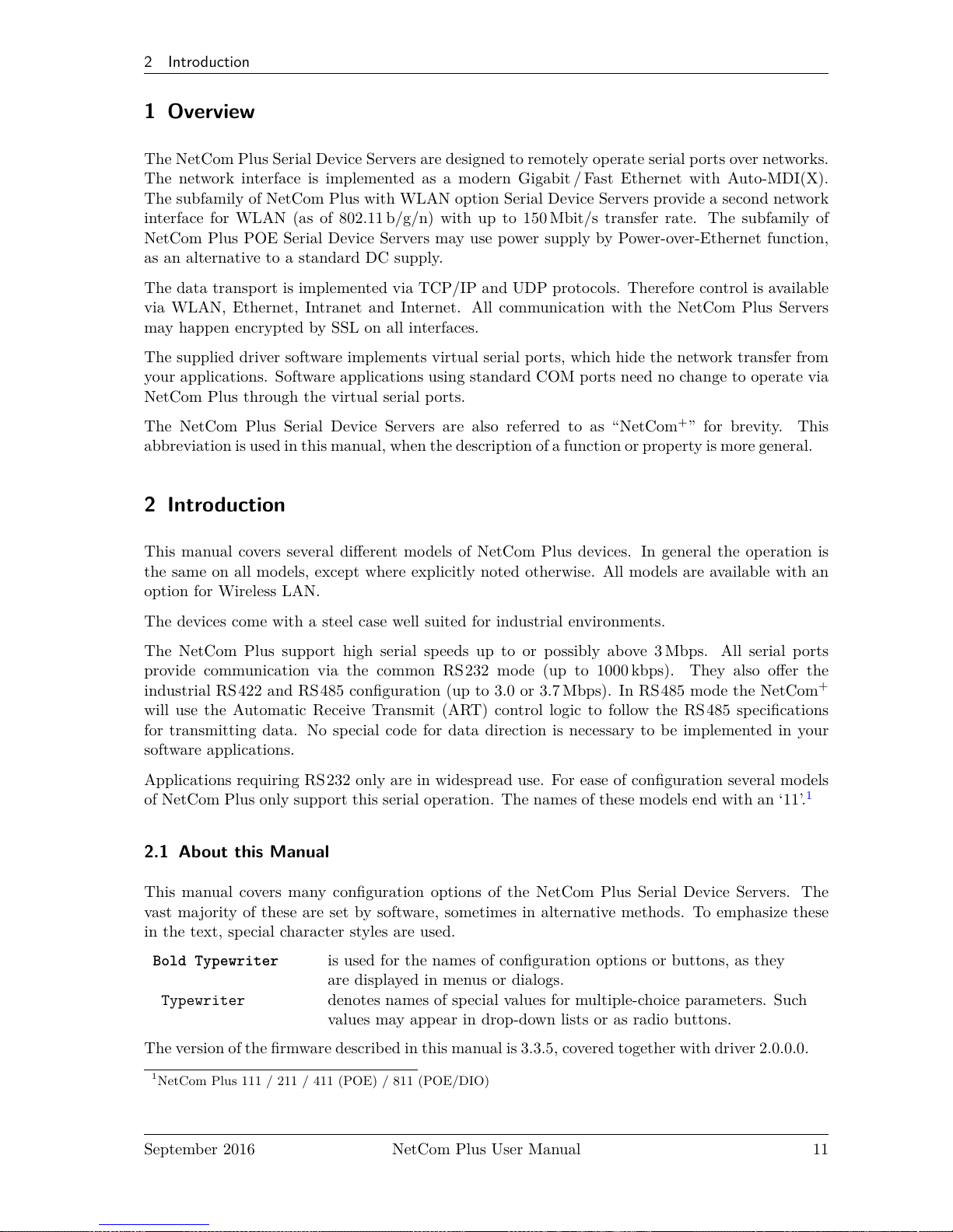
The NetCom Plus Serial Device Servers are designed to remotely operate serial ports over networks.
The network interface is implemented as a modern Gigabit / Fast Ethernet with Auto-MDI(X).
The subfamily of NetCom Plus with WLAN option Serial Device Servers provide a second network
interface for WLAN (as of 802.11 b/g/n) with up to 150 Mbit/s transfer rate. The subfamily of
NetCom Plus POE Serial Device Servers may use power supply by Power-over-Ethernet function,
as an alternative to a standard DC supply.
The data transport is implemented via TCP/IP and UDP protocols. Therefore control is available
via WLAN, Ethernet, Intranet and Internet. All communication with the NetCom Plus Servers
may happen encrypted by SSL on all interfaces.
The supplied driver software implements virtual serial ports, which hide the network transfer from
your applications. Software applications using standard COM ports need no change to operate via
NetCom Plus through the virtual serial ports.
The NetCom Plus Serial Device Servers are also referred to as “NetCom+” for brevity. This
abbreviation is used in this manual, when the description of a function or property is more general.
2 Introduction
This manual covers several different models of NetCom Plus devices. In general the operation is
the same on all models, except where explicitly noted otherwise. All models are available with an
option for Wireless LAN.
The devices come with a steel case well suited for industrial environments.
The NetCom Plus support high serial speeds up to or possibly above 3 Mbps. All serial ports
provide communication via the common RS232 mode (up to 1000 kbps). They also offer the
industrial RS422 and RS485 configuration (up to 3.0 or 3.7 Mbps). In RS485 mode the NetCom
+
will use the Automatic Receive Transmit (ART) control logic to follow the RS 485 specifications
for transmitting data. No special code for data direction is necessary to be implemented in your
software applications.
Applications requiring RS232 only are in widespread use. For ease of configuration several models
of NetCom Plus only support this serial operation. The names of these models end with an ‘11’.
1
2.1 About this Manual
This manual covers many configuration options of the NetCom Plus Serial Device Servers. The
vast majority of these are set by software, sometimes in alternative methods. To emphasize these
in the text, special character styles are used.
Bold Typewriter is used for the names of configuration options or buttons, as they
are displayed in menus or dialogs.
Typewriter denotes names of special values for multiple-choice parameters. Such
values may appear in drop-down lists or as radio buttons.
The version of the firmware described in this manual is 3.3.5, covered together with driver 2.0.0.0.
1
NetCom Plus 111 / 211 / 411 (POE) / 811 (POE/DIO)
September 2016 NetCom Plus User Manual 11
Page 12
2 Introduction
2.2 Features
• Single power supply NetCom Plus
DC 9-54V, 800 mA@12V
• Double power supply NetCom Plus POE
DC 15-54V, 800 mA@15V
Power over Ethernet 802.3af Class 0
• Wireless LAN 802.11 b/g/n for 150Mbit/s as an option
• Gigabit Ethernet 1000/100/10 Mbps for auto-configuration
• Three way serial port interfaces: RS232/ RS422/RS 485
• USB 2.0 port for Expansion of serial ports via USB–COM Plus modules
• Max. 3.0/3.7 Mbps, half- and full-duplex
• TCP/IP configuration fixed or by DHCP
• Easy remote configuration via SNMP
• Drivers for Windows™ operating systems
• Documented interface for every networked operating system
2.3 Product Specifications
Most of the hardware characteristics are common for all models. However some must differ from
model to model, they are shown in dedicated sections. Some models are restricted to RS232, others
do have a POE supply.
Most models provide an USB 2.0 high-speed port. This may be used for a USB WLAN adapter
or to add more serial ports via USB–COM Plus modules2. The modules provide USB-through
function to add even more ports, in total there may be 16, 24, 32, ... ports.
2
USB–COM Plus modules on VScom.de
September 2016 NetCom Plus User Manual 12
Page 13
2 Introduction
2.3.1 Common characteristics
Hardware Modern ARM processor
WLAN antenna SMA-reverse (optional)
Ethernet connector RJ45 1000Base-T/100BaseTx/10BaseT
Protocols TCP/IP, UDP, SNMP, DHCP, ICMP, ARP, Telnet, RTelnet, HTTP
Serial Speed 180 bps up to 3.0 or 3.7 Mbps 1
Parity None, Even, Odd, Mark, Space
Data bits 7, 8
Stop bits 1, 2
Serial signals
RS232 TxD, RxD, RTS, CTS, DTR, DSR,
DCD, GND
RS422
RS485 4-wire
Tx+/Tx−, Rx+/Rx−,GND
RS485 2-wire Data+/Data−, GND
Serial connector DSub9 male (similar to PC)
Serial operation RS232, RS422/ 485 configured by DIP switch or by software
LED
PWR Red Power, blinks once when ready for
operation
Wifi / WLAN Blue If Wireless LAN is available
RDY Green Lights when ready for operation
Management Serial console, Telnet, Web browser, SNMP
Driver software Windows 10/8.1/8/7/2008/Vista/2003/XP
Management software Driver installation and configuration program, Management console
Operating temp. 0° to 65°C
Approval CE, FCC
Table 1: Specifications, common
Note 1: Serial bitrates above 500 kbps may cause problems when used with RS232. It requires
short cables with low capacity, to reduce load on the serial signals. When using RS422 / 485 there
is no problem using maximum bitrates.
2.3.2 Device specific Characteristics
2.3.2.1 NetCom Plus 111 One Port.
Power Requirement DC 9V to 54V, 250 mA@12V
Power Connector Terminal Block (3.7.1)
Serial Ports 1×RS232
Serial Speed 180 bps up to 1.0 Mbps
Data bits 5, 6, 7, 8
USB Port For Expansion of Ports and WLAN
Dimensions 115×73×25 mm (W×D×H)
Weight 400 g
Table 2: Characteristics of NetCom Plus 111
September 2016 NetCom Plus User Manual 13
Page 14
2 Introduction
2.3.2.2 NetCom Plus 113 One Port.
Power Requirement DC 9V to 54V, 250 mA@12V
Power Connector Terminal Block (3.7.1)
Serial Ports 1×RS232/ RS422/RS 485
Serial Speed 180 bps up to 3.7 Mbps
Data bits 5, 6, 7, 8
USB Port For Expansion of Ports and WLAN
Dimensions 115×73×25 mm (W×D×H)
Weight 400 g
Table 3: Characteristics of NetCom Plus 113
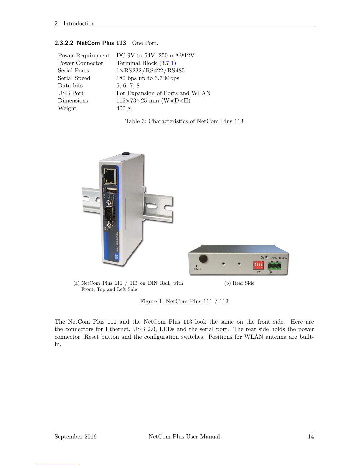
(a) NetCom Plus 111 / 113 on DIN Rail, with
Front, Top and Left Side
(b) Rear Side
Figure 1: NetCom Plus 111 / 113
The NetCom Plus 111 and the NetCom Plus 113 look the same on the front side. Here are
the connectors for Ethernet, USB 2.0, LEDs and the serial port. The rear side holds the power
connector, Reset button and the configuration switches. Positions for WLAN antenna are built-
in.
September 2016 NetCom Plus User Manual 14
Page 15
2 Introduction
2.3.2.3 NetCom Plus 211 Two Ports.
Power Requirement DC 9V to 54V, 250 mA@12V
Power Connector Terminal Block (3.7.1)
Serial Ports 2×RS232
Serial Speed 180 bps up to 1.0 Mbps
Data bits 5, 6, 7, 8
USB Port For Expansion of Ports and WLAN
Dimensions 115×73×25 mm (W×D×H)
Weight 400 g
Table 4: Characteristics of NetCom Plus 211
2.3.2.4 NetCom Plus 213 Two Ports.
Power Requirement DC 9V to 54V, 250 mA@12V
Power Connector Terminal Block (3.7.1)
Serial Ports 2×RS232/ RS422/RS 485
Serial Speed 180 bps up to 3.7 Mbps
Data bits 5, 6, 7, 8
USB Port For Expansion of Ports and WLAN
Dimensions 115×73×25 mm (W×D×H)
Weight 400 g
Table 5: Characteristics of NetCom Plus 213
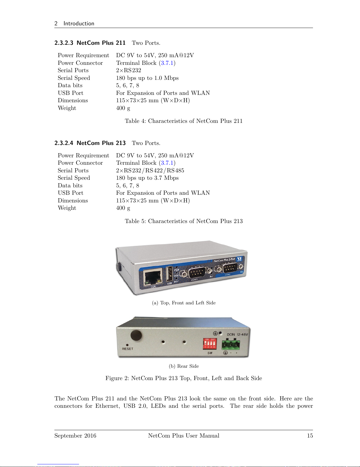
(a) Top, Front and Left Side
(b) Rear Side
Figure 2: NetCom Plus 213 Top, Front, Left and Back Side
The NetCom Plus 211 and the NetCom Plus 213 look the same on the front side. Here are the
connectors for Ethernet, USB 2.0, LEDs and the serial ports. The rear side holds the power
September 2016 NetCom Plus User Manual 15
Page 16
2 Introduction
connector, Reset button and the configuration switches. DIN Rail mounting clamp is fixed here.
Positions for WLAN antenna are built-in.
2.3.2.5 NetCom Plus 411 Four Ports.
Power Requirement DC 9V to 54V, 600 mA@12V
Power Connector Terminal Block (3.7.1)
Serial Ports 4×RS232
Serial Speed 180 bps up to 1.0 Mbps
Data bits 7, 8
USB Port For Expansion of Ports and WLAN
Dimensions 196×147×44 mm (W×D×H)
Weight 900 g
Table 6: Characteristics of NetCom Plus 411
2.3.2.6 NetCom Plus 411 POE Four Ports.
Power Requirement DC 15V to 54V, 600 mA@15V
(DC 15V to 54V on some samples)
Power Connector Terminal Block (3.7.1)
Power Alternative Power over Ethernet PoE 802.3af Class 0
Serial Ports 4×RS232
Serial Speed 180 bps up to 500 kbps
Data bits 7, 8
Dimensions 196×147×44 mm (W×D×H)
Weight 900 g
Table 7: Characteristics of NetCom Plus 411 POE
Note: RDY (Ready) LED is blue
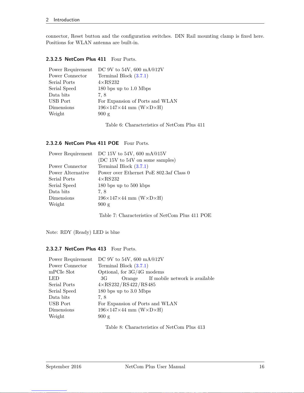
2.3.2.7 NetCom Plus 413 Four Ports.
Power Requirement DC 9V to 54V, 600 mA@12V
Power Connector Terminal Block (3.7.1)
mPCIe Slot Optional, for 3G/4G modems
LED
3G Orange If mobile network is available
Serial Ports 4×RS232/ RS422/RS 485
Serial Speed 180 bps up to 3.0 Mbps
Data bits 7, 8
USB Port For Expansion of Ports and WLAN
Dimensions 196×147×44 mm (W×D×H)
Weight 900 g
Table 8: Characteristics of NetCom Plus 413
September 2016 NetCom Plus User Manual 16
Page 17
2 Introduction
2.3.2.8 NetCom Plus 413 POE Four Ports.
Power Requirement DC 9V to 54V, 600 mA@15V
(DC 15V to 54V on some samples)
Power Connector Terminal Block (3.7.1)
Power Alternative Power over Ethernet PoE 802.3af Class 0
mPCIe Slot Optional, for 3G/4G modems
LED
3G Orange If mobile network is available
Serial Ports 4×RS232/ RS422/RS 485
Serial Speed 180 bps up to 3.0 Mbps
Data bits 7, 8
USB Port For Expansion of Ports and WLAN
Dimensions 196×147×44 mm (W×D×H)
Weight 900 g
Table 9: Characteristics of NetCom Plus 413 POE
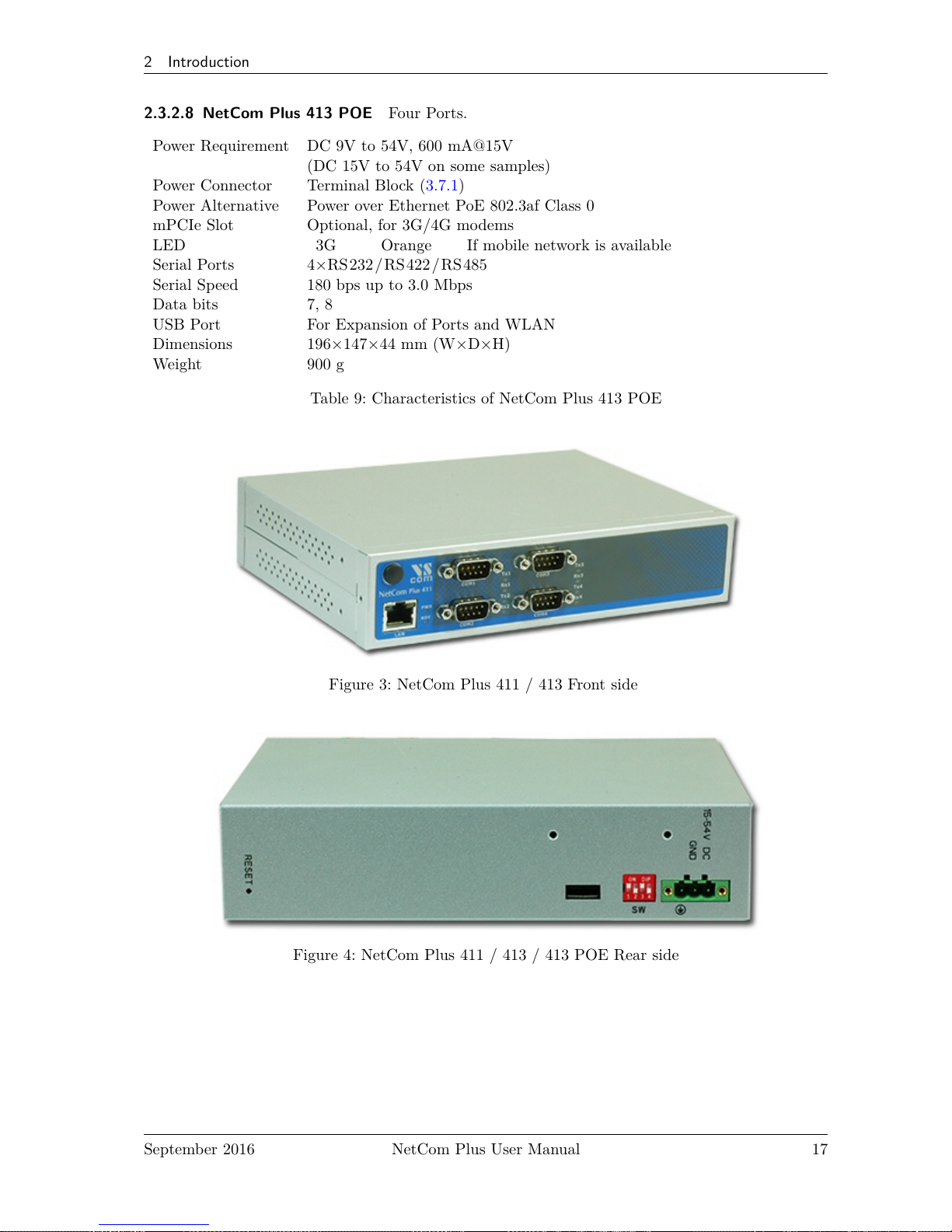
Figure 3: NetCom Plus 411 / 413 Front side
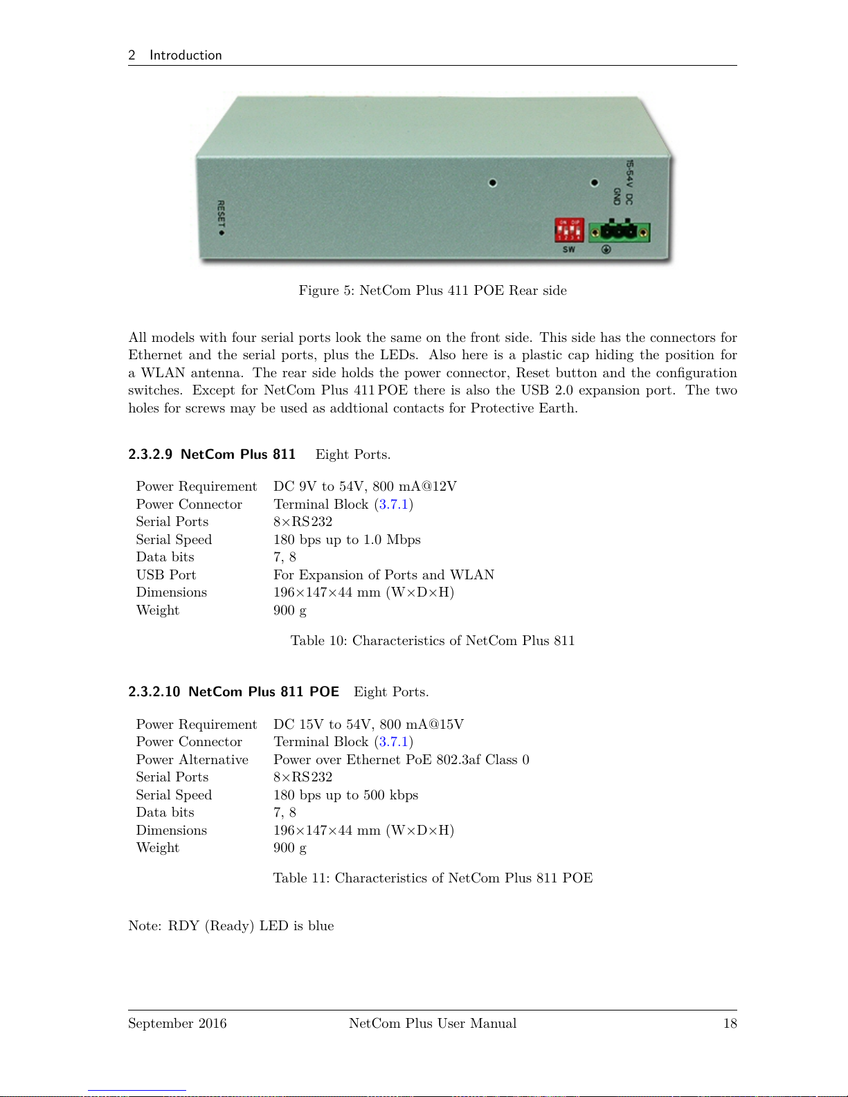
Figure 4: NetCom Plus 411 / 413 / 413 POE Rear side
September 2016 NetCom Plus User Manual 17
Page 18
2 Introduction
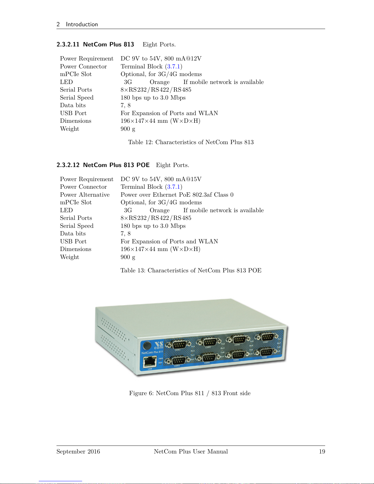
Figure 5: NetCom Plus 411 POE Rear side
All models with four serial ports look the same on the front side. This side has the connectors for
Ethernet and the serial ports, plus the LEDs. Also here is a plastic cap hiding the position for
a WLAN antenna. The rear side holds the power connector, Reset button and the configuration
switches. Except for NetCom Plus 411 POE there is also the USB 2.0 expansion port. The two
holes for screws may be used as addtional contacts for Protective Earth.
2.3.2.9 NetCom Plus 811 Eight Ports.
Power Requirement DC 9V to 54V, 800 mA@12V
Power Connector Terminal Block (3.7.1)
Serial Ports 8×RS232
Serial Speed 180 bps up to 1.0 Mbps
Data bits 7, 8
USB Port For Expansion of Ports and WLAN
Dimensions 196×147×44 mm (W×D×H)
Weight 900 g
Table 10: Characteristics of NetCom Plus 811
2.3.2.10 NetCom Plus 811 POE Eight Ports.
Power Requirement DC 15V to 54V, 800 mA@15V
Power Connector Terminal Block (3.7.1)
Power Alternative Power over Ethernet PoE 802.3af Class 0
Serial Ports 8×RS232
Serial Speed 180 bps up to 500 kbps
Data bits 7, 8
Dimensions 196×147×44 mm (W×D×H)
Weight 900 g
Table 11: Characteristics of NetCom Plus 811 POE
Note: RDY (Ready) LED is blue
September 2016 NetCom Plus User Manual 18
Page 19
2 Introduction
2.3.2.11 NetCom Plus 813 Eight Ports.
Power Requirement DC 9V to 54V, 800 mA@12V
Power Connector Terminal Block (3.7.1)
mPCIe Slot Optional, for 3G/4G modems
LED
3G Orange If mobile network is available
Serial Ports 8×RS232/ RS422/RS 485
Serial Speed 180 bps up to 3.0 Mbps
Data bits 7, 8
USB Port For Expansion of Ports and WLAN
Dimensions 196×147×44 mm (W×D×H)
Weight 900 g
Table 12: Characteristics of NetCom Plus 813
2.3.2.12 NetCom Plus 813 POE Eight Ports.
Power Requirement DC 9V to 54V, 800 mA@15V
Power Connector Terminal Block (3.7.1)
Power Alternative Power over Ethernet PoE 802.3af Class 0
mPCIe Slot Optional, for 3G/4G modems
LED
3G Orange If mobile network is available
Serial Ports 8×RS232/ RS422/RS 485
Serial Speed 180 bps up to 3.0 Mbps
Data bits 7, 8
USB Port For Expansion of Ports and WLAN
Dimensions 196×147×44 mm (W×D×H)
Weight 900 g
Table 13: Characteristics of NetCom Plus 813 POE
Figure 6: NetCom Plus 811 / 813 Front side
September 2016 NetCom Plus User Manual 19
Page 20
2 Introduction
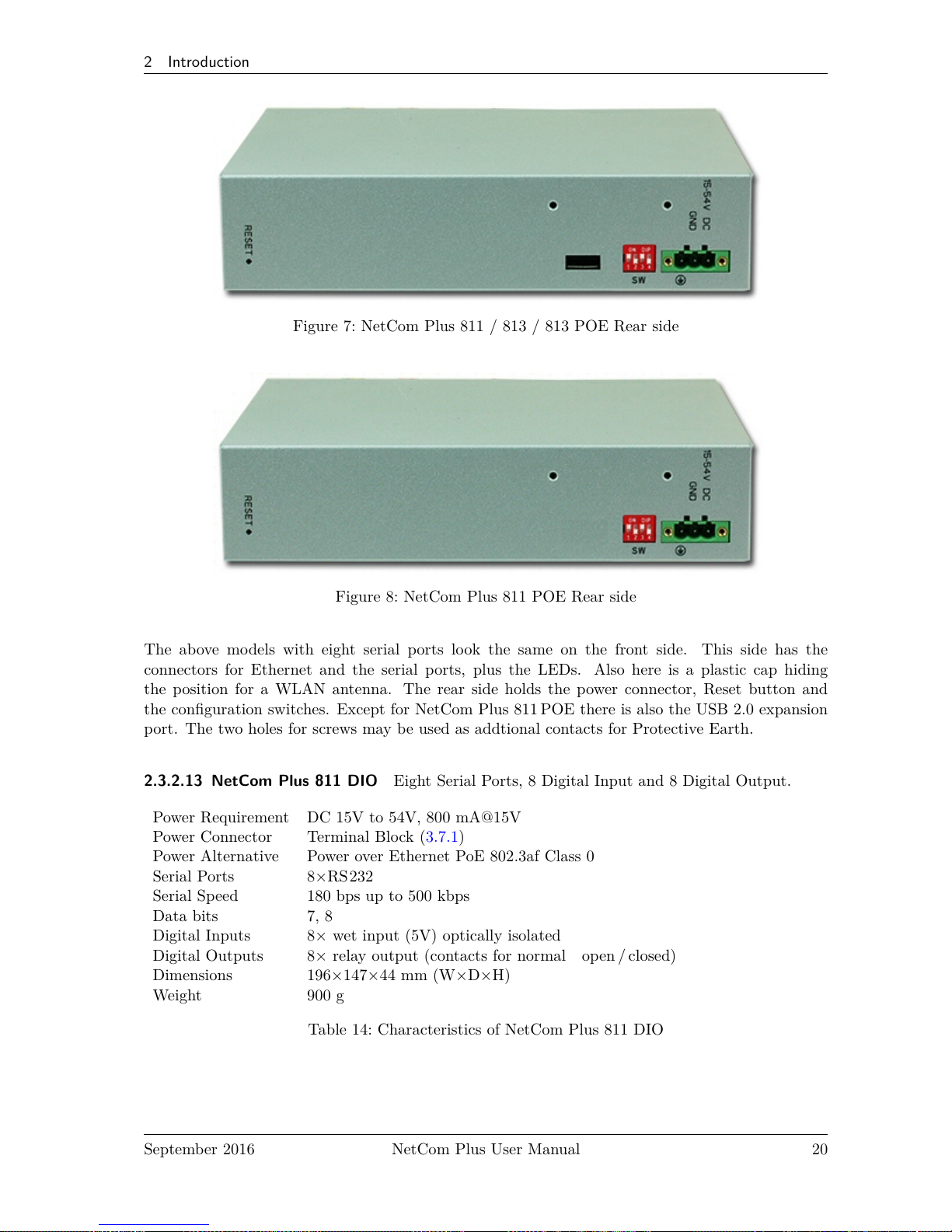
Figure 7: NetCom Plus 811 / 813 / 813 POE Rear side
Figure 8: NetCom Plus 811 POE Rear side
The above models with eight serial ports look the same on the front side. This side has the
connectors for Ethernet and the serial ports, plus the LEDs. Also here is a plastic cap hiding
the position for a WLAN antenna. The rear side holds the power connector, Reset button and
the configuration switches. Except for NetCom Plus 811 POE there is also the USB 2.0 expansion
port. The two holes for screws may be used as addtional contacts for Protective Earth.
2.3.2.13 NetCom Plus 811 DIO Eight Serial Ports, 8 Digital Input and 8 Digital Output.
Power Requirement DC 15V to 54V, 800 mA@15V
Power Connector Terminal Block (3.7.1)
Power Alternative Power over Ethernet PoE 802.3af Class 0
Serial Ports 8×RS232
Serial Speed 180 bps up to 500 kbps
Data bits 7, 8
Digital Inputs 8× wet input (5V) optically isolated
Digital Outputs 8× relay output (contacts for normal open / closed)
Dimensions 196×147×44 mm (W×D×H)
Weight 900 g
Table 14: Characteristics of NetCom Plus 811 DIO
September 2016 NetCom Plus User Manual 20
Page 21
2 Introduction
(a) NetCom Plus 811 DIO Front side
(b) NetCom Plus 811 DIO Rear side
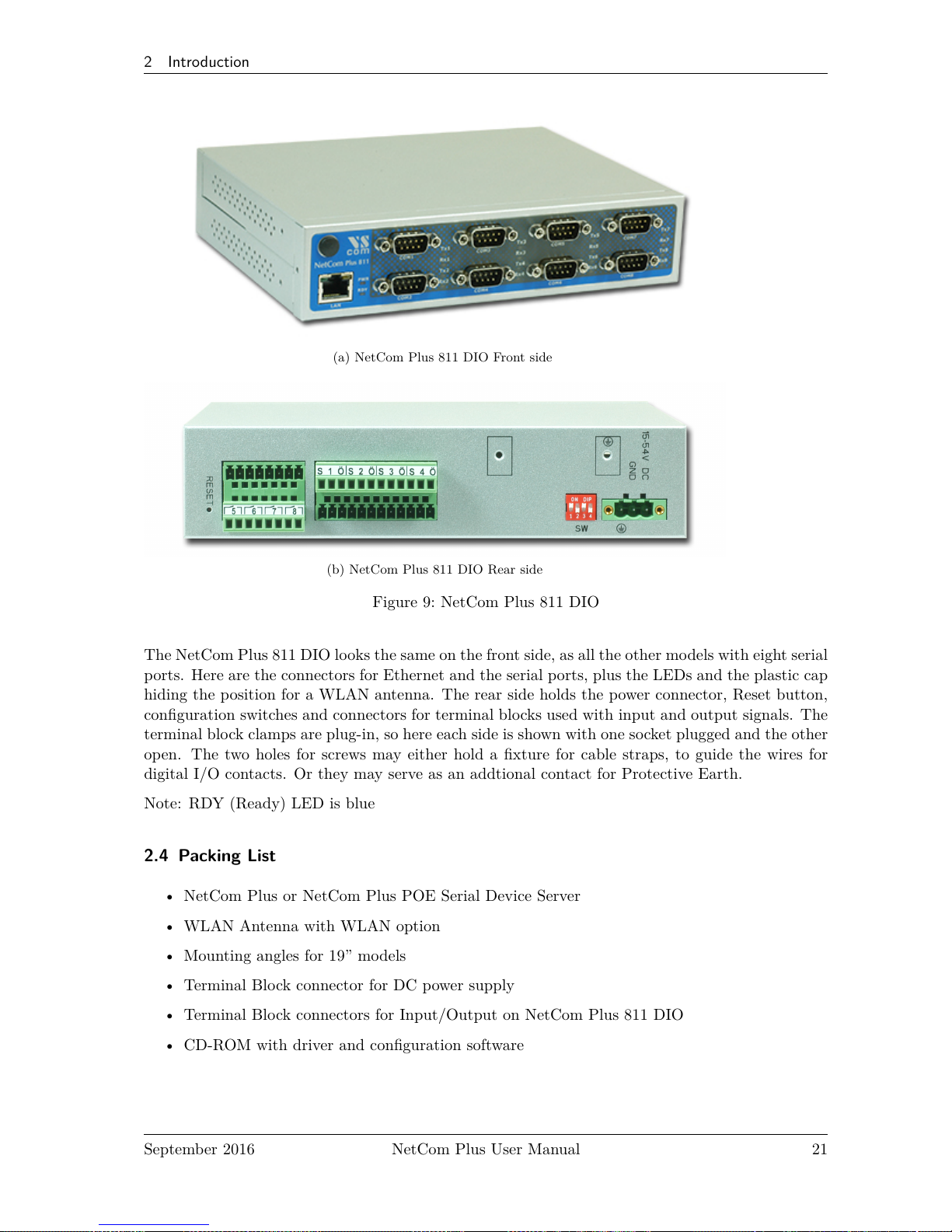
Figure 9: NetCom Plus 811 DIO
The NetCom Plus 811 DIO looks the same on the front side, as all the other models with eight serial
ports. Here are the connectors for Ethernet and the serial ports, plus the LEDs and the plastic cap
hiding the position for a WLAN antenna. The rear side holds the power connector, Reset button,
configuration switches and connectors for terminal blocks used with input and output signals. The
terminal block clamps are plug-in, so here each side is shown with one socket plugged and the other
open. The two holes for screws may either hold a fixture for cable straps, to guide the wires for
digital I/O contacts. Or they may serve as an addtional contact for Protective Earth.
Note: RDY (Ready) LED is blue
2.4 Packing List
• NetCom Plus or NetCom Plus POE Serial Device Server
• WLAN Antenna with WLAN option
• Mounting angles for 19” models
• Terminal Block connector for DC power supply
• Terminal Block connectors for Input/Output on NetCom Plus 811 DIO
• CD-ROM with driver and configuration software
September 2016 NetCom Plus User Manual 21
Page 22
3 Hardware Description
3 Hardware Description
This section focuses on the options provided by the hardware of NetCom Plus Serial Device
Servers.
3.1 Serial Port Configuration
The serial ports in the NetCom+Devices follow the specifications of RS232. On many models
it is also possible to use the serial ports in RS422 or RS 485 mode. This is defined by a set of
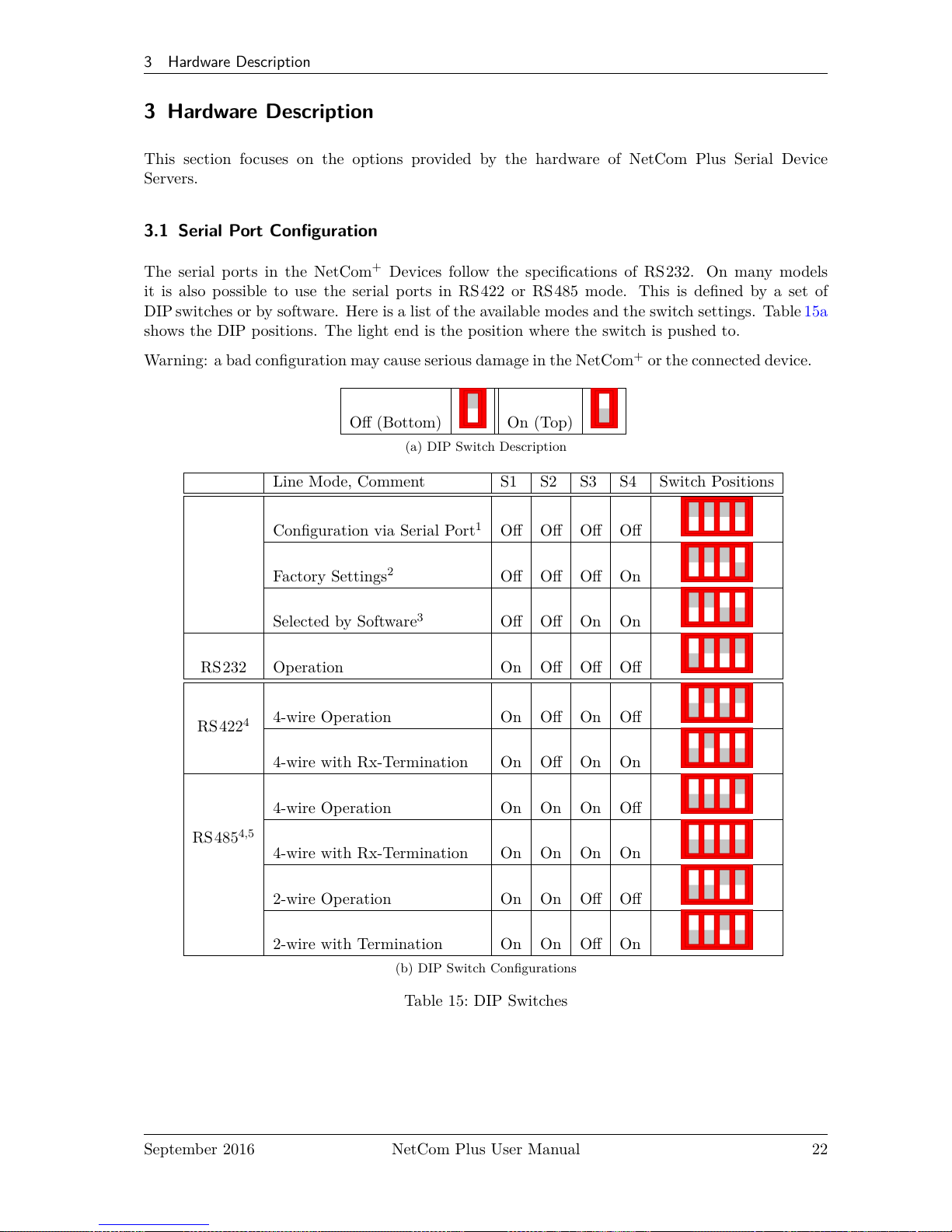
DIP switches or by software. Here is a list of the available modes and the switch settings. Table15a
shows the DIP positions. The light end is the position where the switch is pushed to.
Warning: a bad configuration may cause serious damage in the NetCom+or the connected device.
Off (Bottom) On (Top)
(a) DIP Switch Description
Line Mode, Comment S1 S2 S3 S4 Switch Positions
Configuration via Serial Port1Off Off Off Off
Factory Settings
2
Off Off Off On
Selected by Software
3
Off Off On On
RS232 Operation On Off Off Off
RS422
4
4-wire Operation On Off On Off
4-wire with Rx-Termination On Off On On
RS485
4,5
4-wire Operation On On On Off
4-wire with Rx-Termination On On On On
2-wire Operation On On Off Off
2-wire with Termination On On Off On
(b) DIP Switch Configurations
Table 15: DIP Switches
September 2016 NetCom Plus User Manual 22
Page 23
3 Hardware Description
Note 1: »Configuration via Serial Port« is only effective on port 1 of the NetCom+Server.
Note 2: Factory Settings are restored on Power-Up/Reset of the NetCom+.
Note 3: The Master DIP switches configure all serial ports of a NetCom+to a common
operation mode. If diversity in line operation modes is intended, the switch must
be set to »Selected by Software«, and the configuration may be done via Serial
Port, Telnet, Web browser or SNMP.
Note 4: Line operation modes of RS422 and RS485 are not available on NetCom Plus
111 / 211 /411 / 811 (incl. POE).
Note 5: In RS485 mode the NetCom+performs the required activation and disabling of
the RS485 transmitter by an internal automatic. Application software does not
have to perform special operations.
USB–COM Plus modules may be added for port expansion. These are either configured by their
own DIP switches. Or when the 4- and 8-port modules are set for configuration by software, the
operation mode is controlled by the NetCom Plus in the same way as with the internal ports.
3.2 Serial Signal Assignment
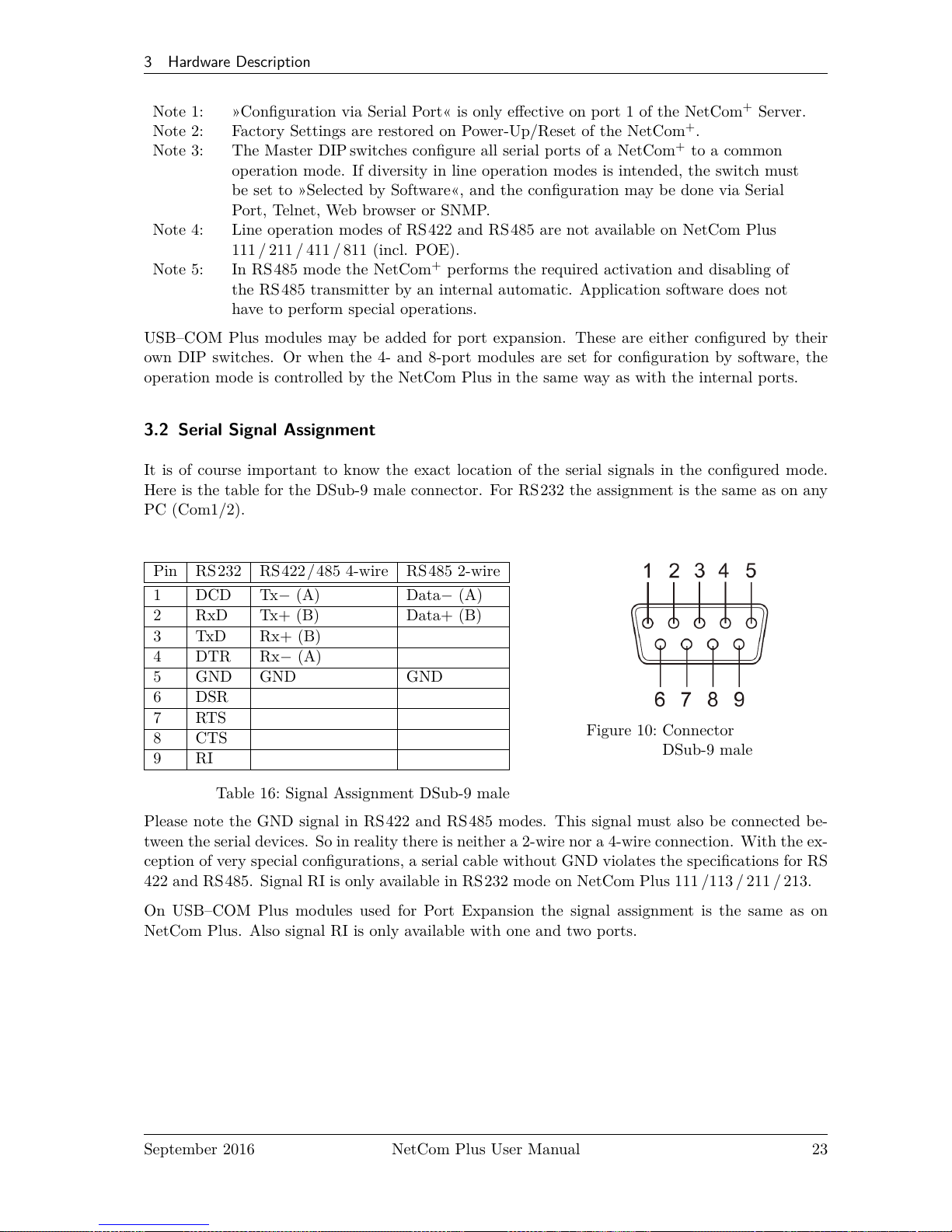
It is of course important to know the exact location of the serial signals in the configured mode.
Here is the table for the DSub-9 male connector. For RS232 the assignment is the same as on any
PC (Com1/2).
Pin RS232 RS422/485 4-wire RS485 2-wire
1 DCD Tx− (A) Data− (A)
2 RxD Tx+ (B) Data+ (B)
3 TxD Rx+ (B)
4 DTR Rx− (A)
5 GND GND GND
6 DSR
7 RTS
8 CTS
9 RI
Table 16: Signal Assignment DSub-9 male
Figure 10: Connector
DSub-9 male
Please note the GND signal in RS422 and RS485 modes. This signal must also be connected be-
tween the serial devices. So in reality there is neither a 2-wire nor a 4-wire connection. With the ex-
ception of very special configurations, a serial cable without GND violates the specifications for RS
422 and RS485. Signal RI is only available in RS 232 mode on NetCom Plus 111 /113 / 211 / 213.
On USB–COM Plus modules used for Port Expansion the signal assignment is the same as on
NetCom Plus. Also signal RI is only available with one and two ports.
September 2016 NetCom Plus User Manual 23
Page 24
3 Hardware Description
3.3 RS422/485 Electrical Configuration
In typical RS422 and RS 485 installations certain electric conditions have to be configured. Simply
connecting cables is not enough to fulfill the specifications of RS422 and RS 485.
For ease of installations the NetCom Plus Serial Device Servers provide the function for often used
Termination. This is activated by selecting the appropriate line operation mode via DIP Switches
(table 15) or by software.
The electrical properties of USB–COM Plus serial ports are identical.
3.3.1 Termination Resistors
The use of long communication lines in RS422 and RS485 mode requires the installation of ter-
mination resistors. These must match the impedance of the cable. Typical cables in Twisted-Pair
configuration have an impedance of about 120Ω. In RS422 and RS485 4-wire this resistor has to
be placed at the end(s) far from the sender, in RS485 2-wire the typical configuration requires one
resistor at each end of the cable.
The NetCom Plus Serial Device Servers provide a suitable termination resistor integrated in the
line drivers, activation is done by selecting the appropriate operation mode.
For values of impedance other than 120Ω the resistors have to be installed directly on the cable.
3.3.2 BIAS Function
RS485 requires a BIAS option for the communication lines. This will guarantee stable electrical
levels on the cables, even at times when no station is transmitting data. Without BIAS there will
be noise on the cable, and sometimes receivers can not detect the first characters of a beginning
communication.
The NetCom Plus Serial Device Servers do not need an explicit BIAS function. With termination
active the idle state of the transmission line is at 0V, which is recognized as a positive level (logic
one) in the receiver circuit. Other devices may require explicit BIAS for a higher voltage at idle
state, e.g. 100mV. In such situation attach that function directly to the cable.
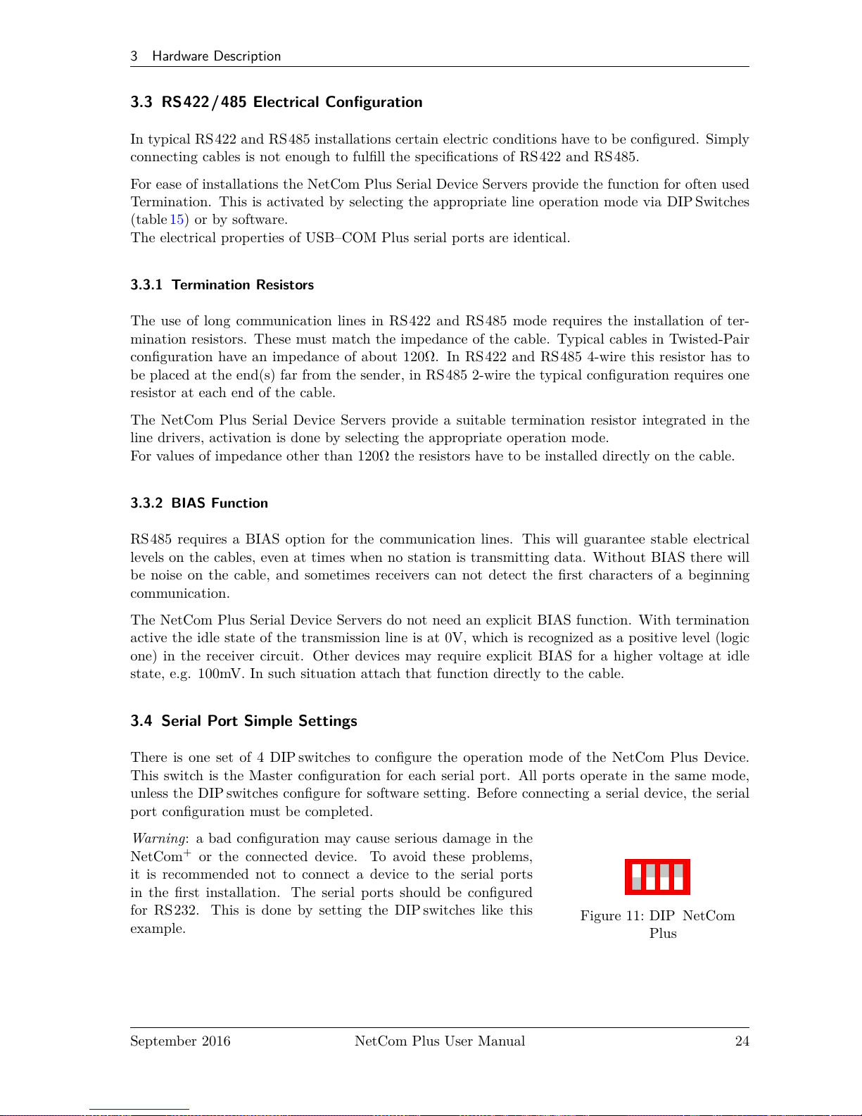
3.4 Serial Port Simple Settings
There is one set of 4 DIPswitches to configure the operation mode of the NetCom Plus Device.
This switch is the Master configuration for each serial port. All ports operate in the same mode,
unless the DIP switches configure for software setting. Before connecting a serial device, the serial
port configuration must be completed.
Warning : a bad configuration may cause serious damage in the
NetCom+or the connected device. To avoid these problems,
it is recommended not to connect a device to the serial ports
in the first installation. The serial ports should be configured
for RS232. This is done by setting the DIP switches like this
example.
Figure 11: DIP NetCom
Plus
September 2016 NetCom Plus User Manual 24
Page 25
3 Hardware Description
3.5 Digital Input/Output
This function is only available on NetCom Plus 811 DIO. The input signals are optically isolated
from the system, and output function is realized by relay.
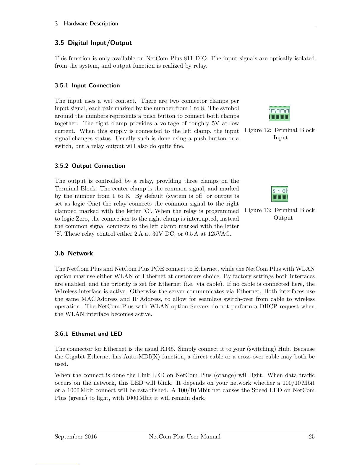
3.5.1 Input Connection
Figure 12: Terminal Block
Input
The input uses a wet contact. There are two connector clamps per
input signal, each pair marked by the number from 1 to 8. The symbol
around the numbers represents a push button to connect both clamps
together. The right clamp provides a voltage of roughly 5V at low
current. When this supply is connected to the left clamp, the input
signal changes status. Usually such is done using a push button or a
switch, but a relay output will also do quite fine.
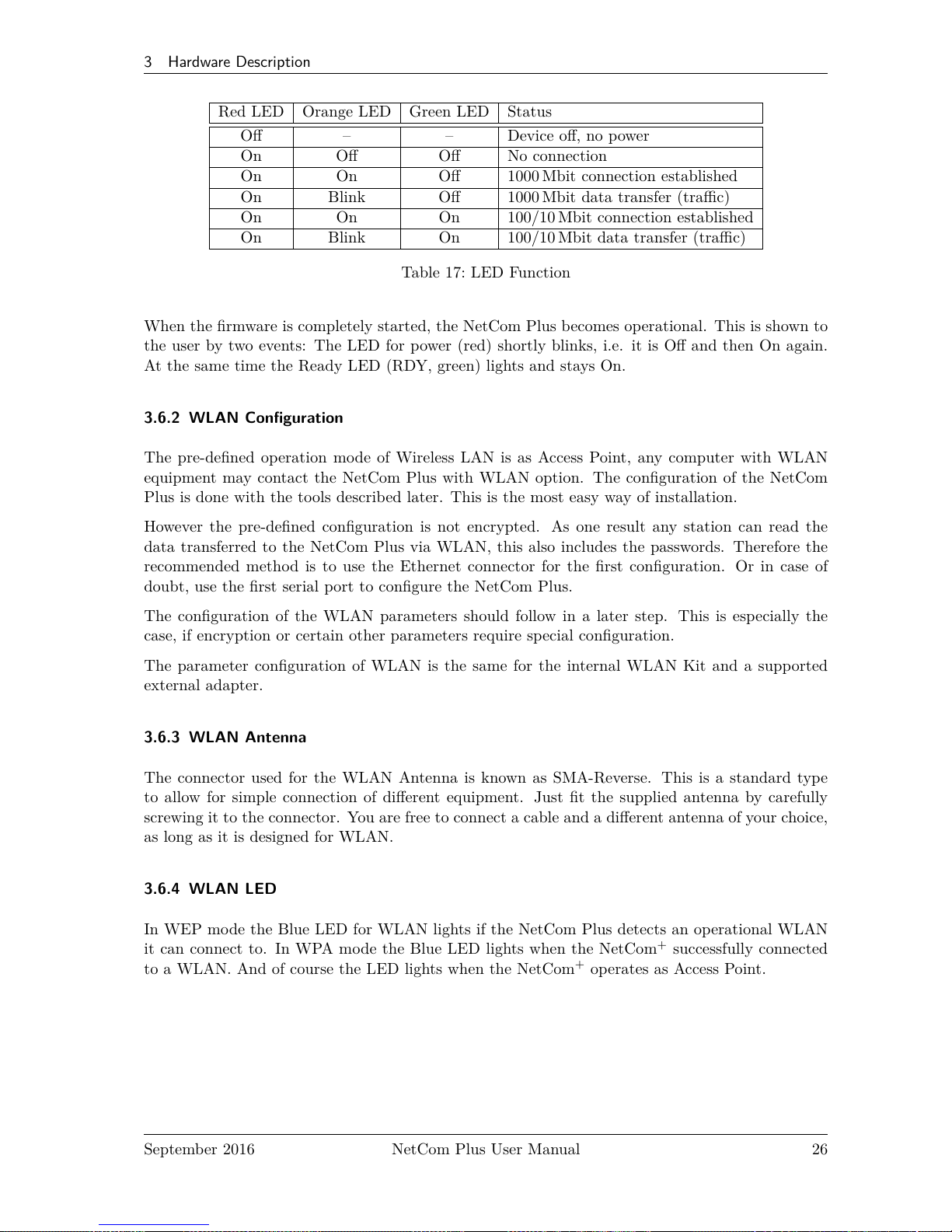
3.5.2 Output Connection
Figure 13: Terminal Block
Output
The output is controlled by a relay, providing three clamps on the
Terminal Block. The center clamp is the common signal, and marked
by the number from 1 to 8. By default (system is off, or output is
set as logic One) the relay connects the common signal to the right
clamped marked with the letter ’Ö’. When the relay is programmed
to logic Zero, the connection to the right clamp is interrupted, instead
the common signal connects to the left clamp marked with the letter
’S’. These relay control either 2 A at 30V DC, or 0.5 A at 125VAC.
3.6 Network
The NetCom Plus and NetCom Plus POE connect to Ethernet, while the NetCom Plus with WLAN
option may use either WLAN or Ethernet at customers choice. By factory settings both interfaces
are enabled, and the priority is set for Ethernet (i.e. via cable). If no cable is connected here, the
Wireless interface is active. Otherwise the server communicates via Ethernet. Both interfaces use
the same MAC Address and IP Address, to allow for seamless switch-over from cable to wireless
operation. The NetCom Plus with WLAN option Servers do not perform a DHCP request when
the WLAN interface becomes active.
3.6.1 Ethernet and LED
The connector for Ethernet is the usual RJ45. Simply connect it to your (switching) Hub. Because
the Gigabit Ethernet has Auto-MDI(X) function, a direct cable or a cross-over cable may both be
used.
When the connect is done the Link LED on NetCom Plus (orange) will light. When data traffic
occurs on the network, this LED will blink. It depends on your network whether a 100/10 Mbit
or a 1000 Mbit connect will be established. A 100/10 Mbit net causes the Speed LED on NetCom
Plus (green) to light, with 1000 Mbit it will remain dark.
September 2016 NetCom Plus User Manual 25
Page 26
3 Hardware Description
Red LED Orange LED Green LED Status
Off – – Device off, no power
On Off Off No connection
On On Off 1000 Mbit connection established
On Blink Off 1000 Mbit data transfer (traffic)
On On On 100/10 Mbit connection established
On Blink On 100/10 Mbit data transfer (traffic)
Table 17: LED Function
When the firmware is completely started, the NetCom Plus becomes operational. This is shown to
the user by two events: The LED for power (red) shortly blinks, i.e. it is Off and then On again.
At the same time the Ready LED (RDY, green) lights and stays On.
3.6.2 WLAN Configuration
The pre-defined operation mode of Wireless LAN is as Access Point, any computer with WLAN
equipment may contact the NetCom Plus with WLAN option. The configuration of the NetCom
Plus is done with the tools described later. This is the most easy way of installation.
However the pre-defined configuration is not encrypted. As one result any station can read the
data transferred to the NetCom Plus via WLAN, this also includes the passwords. Therefore the
recommended method is to use the Ethernet connector for the first configuration. Or in case of
doubt, use the first serial port to configure the NetCom Plus.
The configuration of the WLAN parameters should follow in a later step. This is especially the
case, if encryption or certain other parameters require special configuration.
The parameter configuration of WLAN is the same for the internal WLAN Kit and a supported
external adapter.
3.6.3 WLAN Antenna
The connector used for the WLAN Antenna is known as SMA-Reverse. This is a standard type
to allow for simple connection of different equipment. Just fit the supplied antenna by carefully
screwing it to the connector. You are free to connect a cable and a different antenna of your choice,
as long as it is designed for WLAN.
3.6.4 WLAN LED
In WEP mode the Blue LED for WLAN lights if the NetCom Plus detects an operational WLAN
it can connect to. In WPA mode the Blue LED lights when the NetCom+successfully connected
to a WLAN. And of course the LED lights when the NetCom+operates as Access Point.
September 2016 NetCom Plus User Manual 26
Page 27
3 Hardware Description
3.7 Power Supply
The NetCom Plus devices are powered by a single 9-54V power supply. It requires 70 mA up to
750 mA of current, depending on the device type and voltage supplied. Connect the cable to the
Terminal Block at the rear side of NetCom Plus.
The NetCom Plus 411/ 811 POE devices are either powered by a single 15-54V power supply, in
the same way as the NetCom Plus and NetCom Plus with WLAN option devices; this also applies
to the NetCom Plus 811 DIO. The NetCom Plus 413/813 POE devices use the standard 9-54V
supply.
Or the NetCom Plus POE devices are powered via the network cable, connected to an Ethernet
switch with PoE function as IEEE 802.3af. This switch is referenced as the PSE (Power Sourcing
Equipment), while the NetCom Plus POE is the PD (Powered Device). It indicates itself as a
Class 0 device when sourced by the PSE. An external power adapter has priority over the PoE
function.
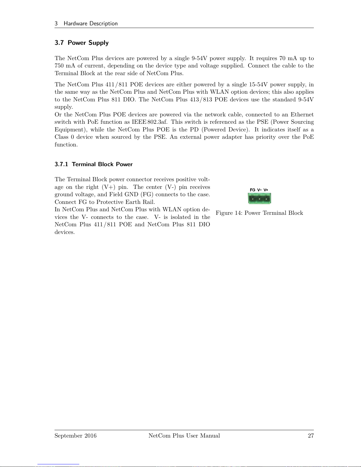
3.7.1 Terminal Block Power
The Terminal Block power connector receives positive volt-
age on the right (V+) pin. The center (V-) pin receives
ground voltage, and Field GND (FG) connects to the case.
Connect FG to Protective Earth Rail.
In NetCom Plus and NetCom Plus with WLAN option de-
vices the V- connects to the case. V- is isolated in the
NetCom Plus 411/811 POE and NetCom Plus 811 DIO
devices.
Figure 14: Power Terminal Block
September 2016 NetCom Plus User Manual 27
Page 28
4 Windows Virtual COM Driver
4 Windows Virtual COM Driver
This chapter covers the use of NetCom+Devices via Virtual Com Ports installed by the supplied
driver software for Windows. Sections 4.1 to 4.3 describe in details the process of driver installation
and removal, as well as updating. This first part here is for quick installation, so only the common
options are covered.
Section 4.4 provides the details of NetCom Plus Manager and also the options available with the
Virtual Com Ports.
4.1 Installation Procedure
Before starting installation, it is essential to have an IP configuration ready for the NetCom+Device
to install. You may read the TCP/IP Description (section 13) below. The default configuration is
based on DHCP, which is fine in many networks. If in doubt, please ask your Network Administrator
for help. Further it is assumed the network access is functional. It is recommended to use Ethernet
via Hub or Cross-Over cable for configuration.
The following description is based on Windows10. The installation on other configurations of
Windows is similar. The installation of drivers is described first. This is followed by a procedure to
verify a correct installation. The last part of this section is about the uninstall or update processes
of drivers and tools.
Drivers are provided for Windows XP up to Windows 10, Windows Server 2003 up to 2008 R2. The
x86 and x64 Editions have separate drivers.
The drivers use the IP Address of NetCom+Servers to operate. So the configuration
of the device should avoid to change that over time. This is either done via a static
IP Address, or by proper configuration of the DHCP server. In the second case
the DHCP server shall recognize the NetCom+by its MAC Address, and assign the
same IP Address each time the device sends a request. All available DHCP Server
products provide such a function, even in SOHO routers.
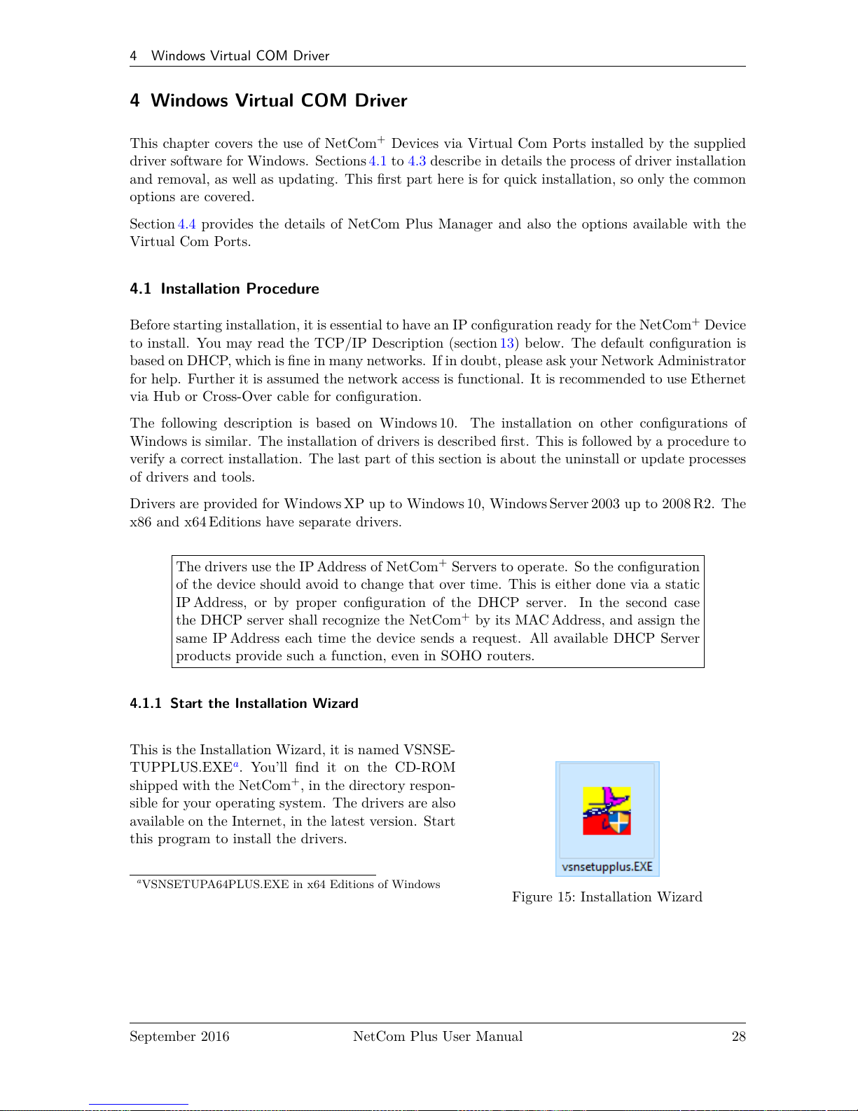
4.1.1 Start the Installation Wizard
Figure 15: Installation Wizard
This is the Installation Wizard, it is named VSNSE-
TUPPLUS.EXEa. You’ll find it on the CD-ROM
shipped with the NetCom+, in the directory respon-
sible for your operating system. The drivers are also
available on the Internet, in the latest version. Start
this program to install the drivers.
a
VSNSETUPA64PLUS.EXE in x64 Editions of Windows
September 2016 NetCom Plus User Manual 28
Page 29
4 Windows Virtual COM Driver
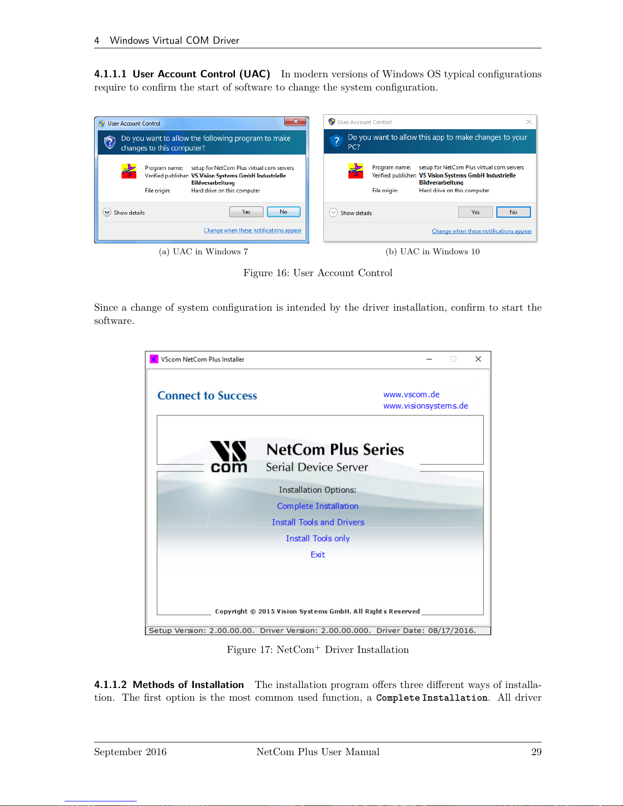
4.1.1.1 User Account Control (UAC) In modern versions of Windows OS typical configurations
require to confirm the start of software to change the system configuration.
(a) UAC in Windows 7 (b) UAC in Windows 10
Figure 16: User Account Control
Since a change of system configuration is intended by the driver installation, confirm to start the
software.
Figure 17: NetCom+Driver Installation
4.1.1.2 Methods of Installation The installation program offers three different ways of installa-
tion. The first option is the most common used function, a Complete Installation. All driver
September 2016 NetCom Plus User Manual 29
Page 30
4 Windows Virtual COM Driver
files and tools are copied to the Windows system, and installed in the Start Menu. Further the
drivers are installed in the system, and the network is searched for available NetCom+. The serial
ports on these devices are installed as Virtual Com Ports in the system.
The second option will Install Tools and Drivers. However the network is not searched for
NetCom+Devices. And of course no serial ports are installed in the system. This function is
designed to prepare a computer for use of NetCom+Virtual Com Ports, but the final installation
shall be skipped for some reasons. For example the computer shall be shipped to a customer, and
the final installation is planned to happen there.
Finally the third option is to Install Tools only, no drivers. At time of writing these tools are the
NetCom Manager, as well as the uninstall and repair functions. This function should be selected
when the use of Virtual Com Port drivers is not intended. The NetCom+Devices may be used in
many different operation modes covered later (6).
There are also some Hyperlinks, opening access to more recent driver versions.
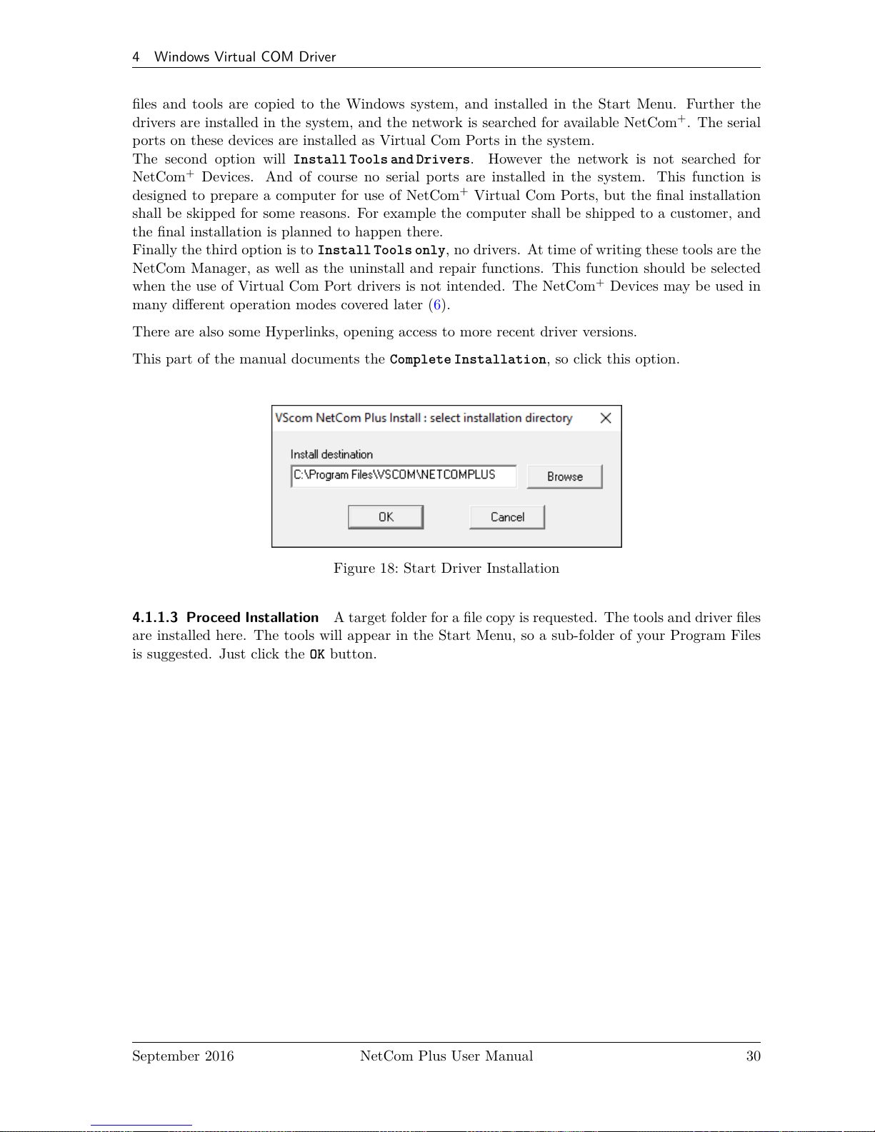
This part of the manual documents the Complete Installation, so click this option.
Figure 18: Start Driver Installation
4.1.1.3 Proceed Installation A target folder for a file copy is requested. The tools and driver files
are installed here. The tools will appear in the Start Menu, so a sub-folder of your Program Files
is suggested. Just click the OK button.
September 2016 NetCom Plus User Manual 30
Page 31

4 Windows Virtual COM Driver
Figure 19: Copy Driver Files
Some files are copied to your hard disk, this is the usual process similar to other Windows installa-
tions. The upper bar increases with the progress of each step performed in the installation process.
The lower bar illustrates each step performed until full installation is finished.
4.1.1.4 Request for Trust While copying the files, the drivers are also installed on the system.
There is another request from Windows for confirmation.
Figure 20: Install Request
September 2016 NetCom Plus User Manual 31
Page 32

4 Windows Virtual COM Driver
Note: No component is actually installed at this moment. Windows is just preparing to load the
drivers, once the NetCom Plus Manager instructs to do so. This request will come twice, to make
it more easy just tick the Always trust option.
4.1.2 Find and Configure NetCom+Devices
When all files are copied, the NetCom Plus Manager3program is started. Since Windows 7 ad-
ministrative privileges are not sufficient to perform every kind of operation on network functions.
The Windows firewall requires special treatment, and the Manager askes for permission on that.
Figure 21: Firewall options
The options in drop down:
Add Firewall Exception adds a temporary entry in the firewall rules. This allows the NetCom
Plus Manager to more generally receive certain messages on the network. When the Manager
is finished this rule is removed.
Turn off Firewall does exactly that. The Windows Firewall is disabled completely. This should
never be necessary, and is an option of last resort in case of trouble.
Do nothing, continue does nothing as suggested. It is the understanding the current configuration
of IP Parameters is sufficient. However some NetCom+might be missed in the search.
Abort is an option to stop the Manager from performing any action.
This request will appear on every start of the NetCom Plus Manager, and with certain operations
in Windows Device Manager as well. In most installations the user will always select the same
option again and again. The option named Permanent instructs the Manager to memorize the
current selection. On the next start the selected action is performed without any request to the
user.
The option Turn Off Firewall on Failure will disable the firewall, if the selected action results
in any problems.
This Manager then searches for all NetCom+Devices on your network.
3
This program is covered in detail in 4.4. For now follow the minimum steps.
September 2016 NetCom Plus User Manual 32
Page 33

4 Windows Virtual COM Driver
Figure 22: Discover and Select NetCom+Devices for Installation
Figure 23: NetCom+in Manager
After short time the search process is finished. All the
discovered NetCom+are listed. In your very first installa-
tion of NetCom+Devices and Drivers you should connect
only one NetCom+to your network. This single Device
is listed here. Identify it by comparing the serial number
shown in the NetCom Manager.
4.1.2.1 Configure IP Parameters As mentioned above, it is important to configure the NetCom
+
to operate in your network. In many networks this is done by a special server (DHCP). Please ask
your Network Administrator for information. If you need to define parameters manually, double-
click the devices icon.
September 2016 NetCom Plus User Manual 33
Page 34

4 Windows Virtual COM Driver
Figure 24: Define NetCom+s IP Configuration
This panel opens. Deselect the Option of Use DHCP, and place your parameters as IP address,
Netmask and Broadcast. Click on the OK button. You may also enter a DNS name instead of the
IP Address.
Figure 25: DNS Name for NetCom+Server
Click the DNS button, and enter the Qualified Domain Name defining the NetCom+Server. Your
Administrator will provide you with it. This name is translated to an IP Address and used by the
driver.
When all parameters of the configuration are set, click the OK button. This will update the config-
uration of the NetCom+, the new parameters are sent to the device.
September 2016 NetCom Plus User Manual 34
Page 35

4 Windows Virtual COM Driver
Figure 26: Sending Parameters to a NetCom
+
4.1.2.2 Configure Firewall As you will notice in figure 24 the driver may also operate by traversal
of a Network Firewall. This requires a special configuration, which is skipped here. Please read in
detail in section 5.5 on page 55. For now proceed with the standard installation.
4.1.3 Install Drivers
You are now back in the NetCom Plus Manager. Click the OK button, the installation continues.
Windows detects the serial ports on the fresh NetCom+as new Hardware. All new Virtual Com
Ports are installed without manual intervention by the user.
Figure 27: Virtual Com Ports installing in Windows 7
In Windows 7 you may watch the process by using the alert icon in the notification area.
September 2016 NetCom Plus User Manual 35
Page 36

4 Windows Virtual COM Driver
(a) Server first
(b) then Com Ports
Figure 28: Virtual Com Ports installing in Windows 10
In Windows 10 everything happens in the Device Manager. You may notice the installation of the
NetCom+, followed by the Virtual Com Ports appearing one after the other.
4.2 Verify the Installation
Figure 29: VScom drivers in the Start Menu
In the Start Menu you’ll find the new pro-
gram group "VScom NetCom Plus". The in-
stalled programs are the NetCom Plus Manager
and a Driver Repair program.
September 2016 NetCom Plus User Manual 36
Page 37

4 Windows Virtual COM Driver
Figure 30: NetCom+in Device Manager
In the Device Manager the serial ports are listed in the usual section Ports. Additionally there
is the device class Multi-port serial adapters. All installed NetCom+Devices are listed herein.
The available options are described later.
4.3 Update the Drivers and Tools
As suggested by figure 47 the Installation Wizard offers an option to Update the drivers to a new
version. Windows itself also offers an option to update the drivers of installed devices. Although this
is a functional option, the correct operation of the NetCom+drivers depends on a common version
for all drivers. The secure way to perform such an update is to run the Installation Wizard. All
driver files are replaced by later versions simultaneously, and all configuration data (Com number,
special port configurations, ...) is preserved.
September 2016 NetCom Plus User Manual 37
Page 38

4 Windows Virtual COM Driver
4.4 Configuration of the Virtual COM Driver
If properly configured, the serial ports of the NetCom+Devices appear as Virtual Com Ports in
your computer. The "virtual" means, in the computer is no real hardware related to the serial port,
however the driver offers the full functionality of a serial port to the system. The interface used by
the driver is VCOMM, which in turn is supported by the Windows API. So Windows does not see
a difference to Com1, and also no application should detect the change.
When the serial ports are installed by the Virtual Com driver software, any application may use
them. In the Device Manager they appear as NetCom Plus COM Port (figure 30). Without special
tests a program does not see a difference between Com1 and the virtual Com7. For example the
Hyper Terminal4program has no problem to communicate through these Virtual Com Port. And
this situation is common amongst most programs.
4.4.1 Configure the Serial Ports
A typical application selects a serial port, and opens it. After that it performs the standard
configuration of bits per character, parity settings and number of stop bits. Also the flow control
(handshaking) is defined by the application. Windows sends these requests to the port driver, and
this driver sends the requests to the serial port on the NetCom+.
Figure 31: NetCom+COM Port Serial Settings
4
or PuTTY Terminal Emulation
September 2016 NetCom Plus User Manual 38
Page 39

4 Windows Virtual COM Driver
The same parameters may be pre-configured in the Device Manager. This is done via the Properties
of the NetCom Plus COM Port. In the Local Settings tab these standard parameters are defined.
Since most programs configure these parameters by themselves, the values are very rarely used. A
typical situation is a serial printer attached to this virtual port.
4.4.2 Performance Issues
Operation through the network causes some extra time, which is approximately 5 Milliseconds. For
comparison, with a port internal to the computer this time may be just some 100 Microseconds.
This added time has an impact on reaction times. Some data protocols may be sensible. A lot
of configurations are possible to compensate for this. But these have an effect on the sheer data
throughput of the virtual serial port.
Figure 32: NetCom+COM Port Performance Settings
Consequently the configuration starts on the Performance tab. There are four already defined sets
of parameters.
Best Performance is the default configuration. The driver software and the NetCom+communi-
cate with big data blocks. As a result a reaction on short events on the serial port is
somehow delayed. For applications operating with short data blocks, and waiting for
short answers this is not optimal. It causes transmission delays, called Latency.
September 2016 NetCom Plus User Manual 39
Page 40

4 Windows Virtual COM Driver
Good Performance uses smaller blocks. The Latency may be reduced a little bit, depending on the
application. But the impact on the data throughput is small.
Short Latency mimics a 16C550 with full FIFO enabled, but no network timeouts will occur. This
means the block size is 16, quite small for network operations.
Virtual FIFO Off simulates a deactivated FIFO, which is the fastest setting in terms of latency.
The port is configured as if the FIFO is off, buffers are configured to never wait for a
timeout, hence gaining in best reaction times. The FIFO buffers are not deactivated in
reality, they are still used to prevent data loss.
Driver Defaults returns to the standard settings when enabled.
Advanced opens access to detailed configuration of the operation parameters.
September 2016 NetCom Plus User Manual 40
Page 41

4 Windows Virtual COM Driver
4.4.3 Network & Misc Properties
When you use the Advanced checkbox on the Performance tab, the Network/Misc tab opens
automatically.
Figure 33: NetCom+COM Port Network/Misc Properties
The parameters on this tab control the operation of the driver software on the computer.
Tx Network Buffer Size: If the application sends small chunks of data to the driver, these are
buffered to send them in one large packet. This parameter defines the size of the buffer.
And also the maximum packet size sent to the serial port by the driver software.
Rx Network Buffer Size: This is the size of the buffer to receive data from the NetCom+.
Automatic Trigger: based on internal rules, this checkbox selects a best practice value for Tx
Trigger Level. Deactivate it to control that parameter manually.
Tx Trigger Level: Controls the time when data is sent to the NetCom+. If the Tx buffer holds at
least this amount of data, the driver immediately sends them. If there is less data, the
driver may use a timeout to determine when to send them.
Network Timeout (ms): This is the timeout.
September 2016 NetCom Plus User Manual 41
Page 42

4 Windows Virtual COM Driver
Overspeed: This is a special option, not really related to network communication. There are old
applications, limited in the maximum speed. With Overspeed you define a multiplier.
The baudrate requested by the application is multiplied with this factor. The result is
sent to the NetCom+to configure the serial port. E.g. the application may be limited
to 38,400bps, but there is a modem capable of 230,400 bps on the serial port. Set
Overspeed to a value of 6.000, and configure the application to use 38,400 bps.
Open If Absent: The NetCom+may be used from a computer with a Dial-Up connection. When
this option is used, the driver will delay the connection to NetCom+s serial port. Even
when an application opens the port and configures the parameters, no command is
sent. The connection is established when data is sent to the NetCom+, or when status
information is requested.
Keep Alive: This option will periodically send control information to the NetCom+to check if
the connection is still operational. As a second effect a Dial-Up connection will not
automatically close.
Passive Modem: This option controls how often the driver retrieves Modem status information from
the NetCom+. If activated, the driver never asks for the modem status. Instead the
NetCom+informs the driver of any changes. If an application frequently requests the
Modem status, it gets the last value received. On slow networks like the Internet this
option is recommended.
If inactive, the driver software retrieves the Modem status from the NetCom+serial
port each time the application requests it, but with a maximum frequency of 10 per
second. If the latest retrieved information is not older than 100 milliseconds, this value
is returned.
Simulate Device Off on Connection Loss: When this option is enabled, the NetCom+driver does
not attempt to preserve transmitted data. If on a normal serial port the connected
device is switched off, all data sent to this device gets lost. NetCom+simulates this
behavior. All data sent from the application to the driver is discarded, when the TCP
connection to the NetCom+is lost. The NetCom+driver attempts to re-establish the
connection in regular intervals. When the NetCom+is available again, data may be
transferred from then on.
September 2016 NetCom Plus User Manual 42
Page 43

4 Windows Virtual COM Driver
4.4.4 Remote Settings Properties
The other panel created by activating the Advanced checkbox on the Performance tab, is the
Remote Settings tab.
Figure 34: NetCom+COM Port Remote Settings Properties
The parameters on this tab control the operation of the serial port on the NetCom+Device. They
are defined and activated by the driver software.
Tx Trigger Level: The serial port on the NetCom+Device buffers data for transmission to external
devices. If the amount of data in this buffer drops below this level, the NetCom+is
capable to receive new data. It will send a related event to the driver software.
Rx Trigger Level: When the serial port has received this amount of data, these are sent to the
driver on the connected computer. If the amount is less than this, the NetCom+applies
a timeout of about 5 character times. This means the timeout varies with the serial
transmission speed.
The Remote Flow Control panel signals the NetCom+to perform the handshake on its own. This
is necessary, because the network delay of some milliseconds is to long for reliable operation in
many situations.
September 2016 NetCom Plus User Manual 43
Page 44

4 Windows Virtual COM Driver
Enable: The configuration shown here is active, when the pre-defined performance levels are
used. When using the ‘Advanced’ option, Remote Flow Control is completely disabled.
Enable as required. While it is best practice to configure as figure 34, you can disable
certain events here.
CTS, DSR, Tx XON/XOFF: these control the output of data to the serial port.
RTS, DTR, Rx XON/XOFF: used to stop transmission from the connected device.
An application has the option to use any combination of these methods at the same time. The
command to use them is transferred to the NetCom+. For example, if the port is configured to
use Hardware Flow Control, the NetCom+will control the RTS line, and observe the CTS line.
If requested, any of these methods may be unchecked. In that case the driver software on the
computer will control the lines.
Override App Settings: In rare situations it is necessary to ignore the applications configuration.
Check this box, and select the Flow Control functions to use with the device.
Limits: These buttons are prepared for future software versions.
September 2016 NetCom Plus User Manual 44
Page 45
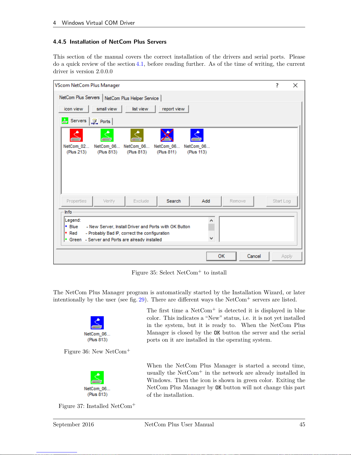
4 Windows Virtual COM Driver
4.4.5 Installation of NetCom Plus Servers
This section of the manual covers the correct installation of the drivers and serial ports. Please
do a quick review of the section 4.1, before reading further. As of the time of writing, the current
driver is version 2.0.0.0
Figure 35: Select NetCom+to install
The NetCom Plus Manager program is automatically started by the Installation Wizard, or later
intentionally by the user (see fig. 29). There are different ways the NetCom+servers are listed.
Figure 36: New NetCom
+
The first time a NetCom+is detected it is displayed in blue
color. This indicates a “New” status, i.e. it is not yet installed
in the system, but it is ready to. When the NetCom Plus
Manager is closed by the OK button the server and the serial
ports on it are installed in the operating system.
Figure 37: Installed NetCom
+
When the NetCom Plus Manager is started a second time,
usually the NetCom+in the network are already installed in
Windows. Then the icon is shown in green color. Exiting the
NetCom Plus Manager by OK button will not change this part
of the installation.
September 2016 NetCom Plus User Manual 45
Page 46

4 Windows Virtual COM Driver
Figure 38: “Bad” NetCom
+
An icon in red color indicates possible problems. To correctly
operate the virtual Com Ports the driver must establish TCP
connections from the PC to the NetCom+. This requires a
matching configuration of IP parameters in the NetCom+and
in the PC. If the NetCom Plus Manager detects such a TCP
connection is not possible with the current configuration, it
displays this warning. Click the Icon, and the right section
of “Info” will show some details to find the problem. If the
NetCom Plus Manager is now closed by the OK button, the
server and the serial ports on it are installed in the operating
system but will not operate correct.
Figure 39: Excluded NetCom
+
Often there are more than only one NetCom+listed. And
sometimes not all of them are to be used on this specific com-
puter. The Exclude button is used for that purpose. Select
a NetCom+Device, and click on that button. The driver will
later ignore this NetCom+, when installing and operating the
serial ports. The Icon changes to olive color.
To later include such a NetCom+, just use the Include button
to change the status. The OK button will then install the server
and serial ports in the system.
Figure 40: Disconnected
NetCom
+
The NetCom Plus Manager holds a list of NetCom+it has
detected on previous occasions. On every start it attempts to
detect these servers again. If for any reason this is not possibe
right now, the icon is shown with a red cross on it.
If a NetCom+has not been operational when the Manager pro-
gram was started, it is either displayed with the cross, or not
displayed at all. You may make it operational by connecting
it now. To install it, use the button Search to find it in the
network. Or Add it manually with that button (section 5.5).
September 2016 NetCom Plus User Manual 46
Page 47

4 Windows Virtual COM Driver
Similarly to the Exclude / Include of specific NetCom+servers, you may do so with selected serial
ports.
Figure 41: NetCom Plus Manager Ports View
Select the Ports section in the Manager. These are the special options used while installing the
driver software. At any time after installation the configuration may be changed by the NetCom
Plus Manager program. This may result in serial ports appearing in or vanishing from the system.
4.4.5.1 Changing the Installation There are common situations, when the current configuration
needs a change. In the first case the NetCom+has a new IP Address, i.e. this has been changed
not using the Manager application. Reasons may be the NetCom+has been moved to a different
location, or the logical structure of the network has changed. Because of the changed address the
driver does not find the serial port to contact.
Figure 42: Reconfigured NetCom+found
Now open the NetCom Manager. It will re-detect the devices. In this process the Manager finds
the already installed NetCom+, but with a new configuration. Confirm this change by clicking
OK here and subsequently in the Manager. The parameters of the installed Virtual Com Port are
changed to contact the same serial ports on a new network address. In the Device Manager of
Windows it may be necessary to search for hardware changes, and then the new parameters are
displayed there.
September 2016 NetCom Plus User Manual 47
Page 48
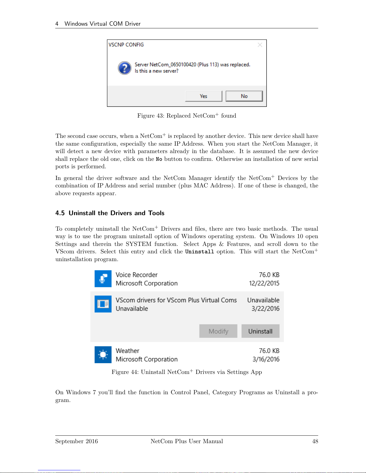
4 Windows Virtual COM Driver
Figure 43: Replaced NetCom+found
The second case occurs, when a NetCom+is replaced by another device. This new device shall have
the same configuration, especially the same IP Address. When you start the NetCom Manager, it
will detect a new device with parameters already in the database. It is assumed the new device
shall replace the old one, click on the No button to confirm. Otherwise an installation of new serial
ports is performed.
In general the driver software and the NetCom Manager identify the NetCom+Devices by the
combination of IP Address and serial number (plus MAC Address). If one of these is changed, the
above requests appear.
4.5 Uninstall the Drivers and Tools
To completely uninstall the NetCom+Drivers and files, there are two basic methods. The usual
way is to use the program uninstall option of Windows operating system. On Windows 10 open
Settings and therein the SYSTEM function. Select Apps & Features, and scroll down to the
VScom drivers. Select this entry and click the Uninstall option. This will start the NetCom
+
uninstallation program.
Figure 44: Uninstall NetCom+Drivers via Settings App
On Windows 7 you’ll find the function in Control Panel, Category Programs as Uninstall a pro-
gram.
September 2016 NetCom Plus User Manual 48
Page 49

4 Windows Virtual COM Driver
Figure 45: Uninstall NetCom+Drivers in Windows 7
Figure 46: Uninstall NetCom+Drivers in Windows 7 Start Menu
As an extra way on Win-
dows 7 you may start the
Uninstall program in the
Start menu.
The other basic method is to start the Installation Wizard again from CD-ROM or the installation
directory.
The Wizard will detect the drivers on the system. You have the options to Repair the current
installation, or to Remove the installed drivers. Since the Installation Wizard is of the same version
as the installed drivers, the option of Update is not available.
Figure 47: Remove, Repair
A Repair replaces the driver files on the system with those in the installation package. Since this
is the same versions, the files should also be the same. If anything is damaged in the installed
drivers, the Repair process will correct the problems.
As expected the Remove process will uninstall drivers and tools from the system. The drivers are
removed from the configuration and also completely deleted from the System drive. This happens
with any configuration data also. Afterward the system is available for a clean installation.
September 2016 NetCom Plus User Manual 49
Page 50

5 Configure with NetCom Manager
5 Configure with NetCom Manager
Shipped with the NetCom+Devices there is a versatile program for Windows Operating System,
named NetCom Plus Manager. This program shall detect, manage and configure the NetCom
+
Devices in your network. You can start it by several ways. First of all it is stored on the CD-ROM,
named NETCOMMGRPLUS.EXE5. It is possible to start it directly from the CD-ROM.
Figure 48: NetCom Plus
Manager
See this Icon. When the Virtual Com Drivers are installed, there are
more options to run the program. Since some operations with NetCom
Plus Manager require administrators privileges, the User Account Con-
trol kicks in.
but many do. So on Windows7 and later, use a right-click on the icon,
and select the »Run as adminstrator...« option.
Also the process of installing the drivers created a new program group
in the Start Menu.
Figure 49: NetCom Manager in Start Menu
This section of documentation focuses on man-
agement of the NetCom+Devices. The options
to configure driver-specific parameters of the se-
rial ports are skipped here. This includes some
buttons and panels. They are described in to-
tal in section 4.4, in the documentation of the
drivers and panels.
While in the configuration process, a click on
a button or a double-click on an item opens
properties or other options. In many situations,
a right-click with the mouse opens context-sensitive options. Just try it out. The NetCom Manager
is designed to help configure driver options. So for very detailed configuration of a NetCom+, it is
better to use the Web browser interface, or do it via Telnet as described in section 6. Here are the
options.
5
NETCOMMGRA64PLUS.EXE in x64 Editions of Windows
September 2016 NetCom Plus User Manual 50
Page 51

5 Configure with NetCom Manager
5.1 Starting NetCom Manager
When NetCom Manager is started, it will ‘Search’ the NetCom+in your LAN by SNMP. This
process may take up to 30 seconds. The devices in a LAN are typically found in the first seconds.
If this is enough for you, you can stop the search by click on the ‘Done’ button.
Figure 50: NetCom Manager Servers Panel
The NetCom+are listed here in the Servers panel. Since the Search uses broadcast mechanisms,
the range is limited. If you have Routers in your network, or you contact some NetCom+via
Internet, you must Add them manually (section 5.5). Enter the network parameters to access the
NetCom+.
Select a NetCom+, and click on the Properties button, double-click the Icon, or use a right click.
Using Verify the NetCom Manager contacts the NetCom+to check if it is properly configured
and online. Exclude is only useful in conjunction with the Virtual Com Drivers, so skipped here.
Search repeats the search from the program start, and may be used at any time. Remove removes
a NetCom+server from this list. This option is most often used to clear old data from the drivers
database. For monitoring purposes you may select a NetCom+, and Start Log for this. It may be
done for several Devices at the same time. The output is visible in the Log Windows panel.
September 2016 NetCom Plus User Manual 51
Page 52

5 Configure with NetCom Manager
5.2 NetCom Server Settings – Info
As described above, open the Properties of a NetCom+Device. The Server Settings start with
the Info panel. Configure the options as your network requires.
Figure 51: NetCom Manager Server Settings - Info
The Server Name is just for information. As factory setting it includes the serial number of the
device. You may change it to any string (of ASCII characters), since there is no functionality related
to the name. This name is listed in the Server panel of NetCom Manager. The next parameters
are fixed, and displayed for information only.
The Telnet port allows to configure this NetCom+via Telnet. The value is a TCP port number.
Factory setting is 23, the standard port for Telnet protocol. By default the NetCom+is set to
Use DHCP for automatic configuration of IP parameters. This is the suggested method. However
there are several situations where this option can not be used. In this case deactivate it. When
inactive, other parameters may be changed. The basic parameters IP address and Netmask are
mandatory. Instead of an IP Address you may enter a DNS name. The NetCom Manager will resolve
that name to the actual IP Address.
September 2016 NetCom Plus User Manual 52
Page 53

5 Configure with NetCom Manager
If address or netmask are changed, the NetCom Manager calculates a matching address for Broadcast.
You may also change this address. The DHCP option will also configure the Default gateway and
the Name server. Without DHCP you must enter these parameters by yourself, enter 0.0.0.0 if they
are not used.
5.3 NetCom Server Settings – Ports
The Ports panel lists all serial ports of a NetCom+. Some of the options are driver related, e.g.
the Com Number. Each serial port may operate via two TCP ports.
Figure 52: NetCom Manager Server Settings - Ports
The TCP Control Port is used in the Virtual Com Driver mode, and also in Null-Modem Tunnel.
If Driver mode is not desired, this parameter is ignored almost always.
The TCP Data Port is used to transmit data to and from the serial port. Use the default, or change
the value to the settings required for your network.
There is also a UDPData Port, used in packet data transfer. You can not switch the NetCom
+
to UDP mode with the Manager. But if it is already in this mode, you can change this basic
parameter.
September 2016 NetCom Plus User Manual 53
Page 54

5 Configure with NetCom Manager
5.4 NetCom Server Settings – Firewall
Many networks use a Firewall to protect the stations in the network from other networks, including
the Internet. In some situations the contact to a NetCom+must pass through such a Firewall
configured for NAT (Network Address Translation, section 15).
Figure 53: NetCom Manager Server Settings - Firewall
To do this you must Enable Firewall, and enter the Address of the Firewall. The address may
be the IP Address, or the Qualified Domain Name (DNS).
The Manager configures a NetCom+via SNMP, which uses UDP. The Firewall must have a special
Port to receive those data, and to transfer it to the internal network. Enter this port here.
The same scheme applies to the logging option. When logging is active a NetCom+listens on
port 1200 for logging connections. The Firewall must also have a special Log Port to receive this
connection, and to transfer it to the NetCom+.
The NetCom+does not need any configuration to operate in a Firewall protected environment.
This configuration here is for installation of the drivers. There is a Firewall tutorial section later
in this manual (5.6).
September 2016 NetCom Plus User Manual 54
Page 55

5 Configure with NetCom Manager
5.5 Manual Detection/Installation of a NetCom
Sometimes the NetCom+Device Server can not be detected by the automatic in the NetCom
Manager. To detect and configure devices the protocol SNMP is used. The detection is done
by sending out a broadcast on all available network interfaces of your computer. This SNMP
broadcast is realized as an Ethernet broadcast. Such a broadcast is only transmitted through
Hubs and Switches. When there is a Router between the computer and the NetCom+, probably
the broadcast is not transmitted further. This is especially the situation when the NetCom+is
located somewhere via Internet, but also in big networks of some companies. If this is the case, the
detection has to be done manually. Refer to figure 35 and Add the NetCom+by use of the button.
Enter the IP Address of the NetCom+in the NetCom Manager Server Settings, and click the button
Verify. Since now the IP Address of the NetCom+is known, the NetCom Manager sends a request
directly to this target, instead of a broadcast. This directed SNMP request is transported, even
by Routers. The NetCom+sends the normal reply, giving all required information to the NetCom
Manager. Now it is possible to configure all options as usual. Also the drivers for virtual serial
ports are installable now.
Please note, the drivers require to have the IP Address. They can not operate using a DNS name,
because the driver can not perform a DNS name resolution. If your NetCom+is located on a
dynamic IP Address (e.g. on a Dial-Up connection with 24 hours disconnection), you need to
reconfigure the driver installation, when the IP Address has changed.
5.6 Firewall Traversal Configuration
There are more difficult situations with a Firewall between the NetCom+and the NetCom Man-
ager. Many Firewalls protect the internal LAN by using the feature of NAT (Network Address
Translation, 15). In this situation the IP Address of the internal device is not visible on the In-
ternet. Only the Firewall can be contacted via its public IP Address. The NetCom Manager and
the driver software for the virtual serial ports can handle such setups. But this requires certain
configurations.
An easy-to-use alternative is the VPN function, which makes Firewall configuration quite easy.
5.6.1 SOHO Firewall example
The most easy situation for such a setup is by using a very simple SOHO Router as the Fire-
wall. This configuration will show the principle of the technical details. Those principles can be
transferred very easy to the configuration of more complicated installations.
On the SOHO Router there is only one public IP Address on the external side, and typically 254
internal private IP Addresses for the LAN side. These internal addresses may be assigned by DHCP
or static. Such Routers offer a feature typically named "DMZ", which in fact is only a single exposed
host. It is recommended not to use the "DMZ" for several reasons, some of them are security related.
Especially it is recommended not to configure a NetCom+as the DMZ host.
September 2016 NetCom Plus User Manual 55
Page 56

5 Configure with NetCom Manager
5.6.2 SOHO Virtual Servers
The Router also offers "Virtual Servers" (here named ViServ for short), which is the option required
for NetCom+installation. These ViServ operate by a technique called PAT (Port Address Trans-
lation, 15). Certain data addressed to the public IPAddress of the Router are forwarded to the
internal private address of the NetCom+. This way the NetCom+can be contacted via the public
IP Address of the Router.
First you need to configure the Router for some ViServs. As the absolute minimum there is one
ViServ for the NetCom+device itself, and another two ViServs for each serial port of the NetCom+.
Those ViServs are to be configured for TCP or UDP transmissions. Please read in the manual of
your Router how to do that. You need a port for the external interface, and an IP Address plus a
port for the LAN side. The LAN IP Address is of course that of the NetCom+. As an example the
most easy device is a NetCom+113 PRO. The internal port for SNMP is 161 for UDP. The serial
port requires ports 2000 and 2001 for TCP.
Function External port Internal port
SNMP 8161/UDP 161/UDP
Control 9000/TCP 2000/TCP
Data 9001/TCP 2001/TCP
Table 18: SOHO Firewall Pass-Through
Configure your Router for these example ViServs, and use the internal IP Address of the NetCom
+
for the targets. Connect the NetCom+to your LAN. Now you are ready for a very first test. Use
Telnet to connect to the Data port of the NetCom+serial port. Open a console (DOS Box) and
type the command
Telnet <Routers-IP-Address> 9001
You will be connected to the serial port. Every character you type is sent out of the serial port,
and every received data is shown on your screen. The serial parameters are pre-configured in your
NetCom+.
5.6.3 NetCom Detection through SOHO Firewall
Now open the NetCom Manager as in section 5.5 above, and click the Add button. You again get the
NetCom Manager Server Settings dialog. But now you have to select the panel named Firewall
(see figure 53).
Check the Option Enable Firewall, and enter the IP Address of the Router in the Address field. In
the field Port enter the target port for the SNMP configuration. From the Virtual Server example
above this is port 8161. Since there is no configured ViServ for Logging, ignore this field. Click
the button Verify to have the NetCom Manager contact the Router. This is a directed request,
so there is no problem with broadcasts. The Router will transfer the request to UDP-Port 161 on
the NetCom+, which is the port for SNMP. The NetCom+will answer the request, and send it out
to your computer. The NAT function in the Router will replace the source IP of the data by its
own public value, so the NetCom Manager will see the answer come from the Router. The NetCom
Manager is satisfied with this data.
September 2016 NetCom Plus User Manual 56
Page 57

5 Configure with NetCom Manager
Some ISP will block the SNMP protocol, which typically means they do not transport data for
161/udp to their customers (this is the first reason why port 8161 was used in the example).
This answer brings every required information about the NetCom+, including its internal IP Address.
Select the panel of NetCom Manager Server Settings to verify the information, but do not make
any changes here. Changing the configuration may disconnect the NetCom+from the protected
LAN.
5.6.4 Serial Ports through SOHO Firewall
Now the NetCom+is available in the NetCom Manager, but still the serial ports are not usable.
The information of the TCP-ports for the ViServ related to the serial port is still missing. In the
NetCom Manager Server Settings select the NetCom Manager Ports Panel. In this panel select one
serial port, in this example of NetCom Plus 111 there is only one serial port. Click the Properties
button to open the configuration of the port.
Figure 54: NetCom Manager Port Configuration for Driver
Since the Firewall function is enabled, the parameters for Firewall mapping are available for
editing. Enter the ports defined in the Router, 9001 and 9000 in this example. Please note, so
far there is no number for the Virtual Com Port available. The driver is not installed in this
moment, and Windows does not know about the available hardware. This will happen later in the
installation. Click the OK button, and proceed with the driver installation as already described.
September 2016 NetCom Plus User Manual 57
Page 58
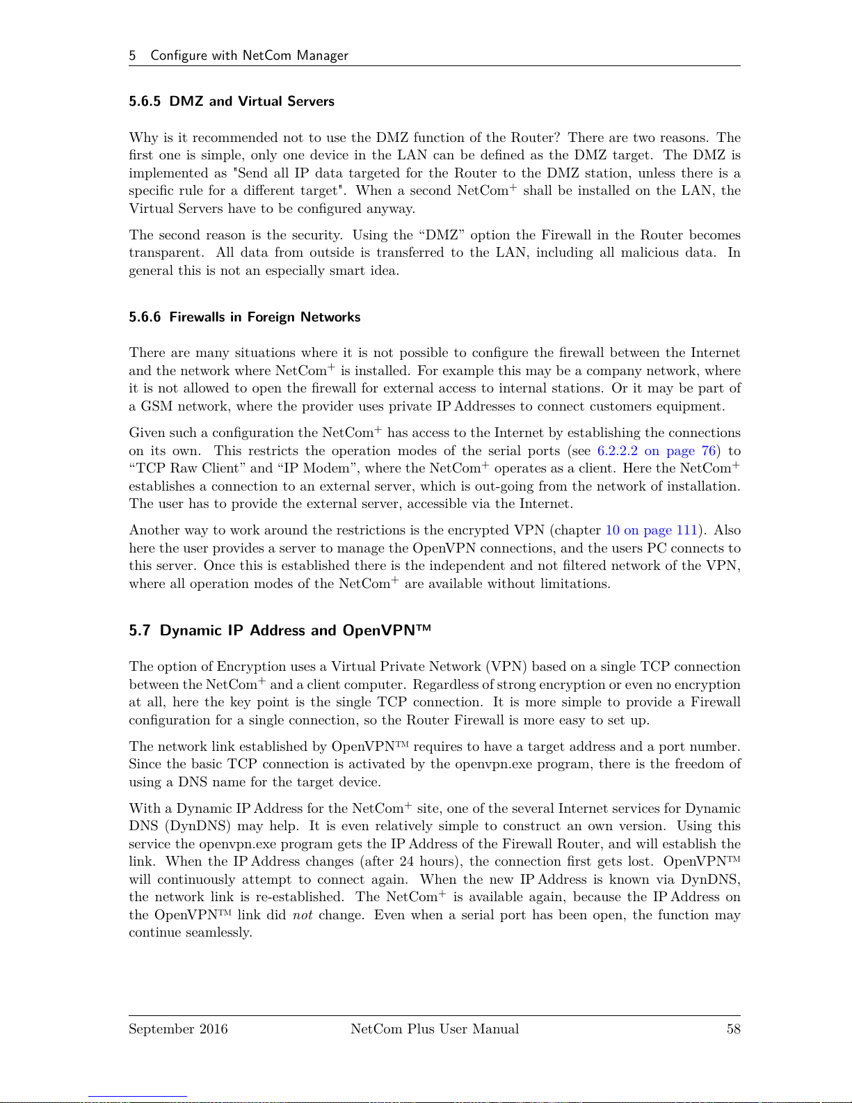
5 Configure with NetCom Manager
5.6.5 DMZ and Virtual Servers
Why is it recommended not to use the DMZ function of the Router? There are two reasons. The
first one is simple, only one device in the LAN can be defined as the DMZ target. The DMZ is
implemented as "Send all IP data targeted for the Router to the DMZ station, unless there is a
specific rule for a different target". When a second NetCom+shall be installed on the LAN, the
Virtual Servers have to be configured anyway.
The second reason is the security. Using the “DMZ” option the Firewall in the Router becomes
transparent. All data from outside is transferred to the LAN, including all malicious data. In
general this is not an especially smart idea.
5.6.6 Firewalls in Foreign Networks
There are many situations where it is not possible to configure the firewall between the Internet
and the network where NetCom+is installed. For example this may be a company network, where
it is not allowed to open the firewall for external access to internal stations. Or it may be part of
a GSM network, where the provider uses private IP Addresses to connect customers equipment.
Given such a configuration the NetCom+has access to the Internet by establishing the connections
on its own. This restricts the operation modes of the serial ports (see 6.2.2.2 on page 76) to
“TCP Raw Client” and “IP Modem”, where the NetCom+operates as a client. Here the NetCom
+
establishes a connection to an external server, which is out-going from the network of installation.
The user has to provide the external server, accessible via the Internet.
Another way to work around the restrictions is the encrypted VPN (chapter 10 on page 111). Also
here the user provides a server to manage the OpenVPN connections, and the users PC connects to
this server. Once this is established there is the independent and not filtered network of the VPN,
where all operation modes of the NetCom+are available without limitations.
5.7 Dynamic IP Address and OpenVPN™
The option of Encryption uses a Virtual Private Network (VPN) based on a single TCP connection
between the NetCom+and a client computer. Regardless of strong encryption or even no encryption
at all, here the key point is the single TCP connection. It is more simple to provide a Firewall
configuration for a single connection, so the Router Firewall is more easy to set up.
The network link established by OpenVPN™ requires to have a target address and a port number.
Since the basic TCP connection is activated by the openvpn.exe program, there is the freedom of
using a DNS name for the target device.
With a Dynamic IP Address for the NetCom+site, one of the several Internet services for Dynamic
DNS (DynDNS) may help. It is even relatively simple to construct an own version. Using this
service the openvpn.exe program gets the IP Address of the Firewall Router, and will establish the
link. When the IP Address changes (after 24 hours), the connection first gets lost. OpenVPN™
will continuously attempt to connect again. When the new IP Address is known via DynDNS,
the network link is re-established. The NetCom+is available again, because the IP Address on
the OpenVPN™ link did not change. Even when a serial port has been open, the function may
continue seamlessly.
September 2016 NetCom Plus User Manual 58
Page 59

6 Configure the Operation Modes
6 Configure the Operation Modes
The NetCom+Devices are often used without the installation of a driver software. Customer
applications contact the NetCom+directly, using network functions. These setups require inde-
pendent configuration of the NetCom+Device and the serial ports. There are four ways to do
this configuration. The NetCom+offers a Web browser interface, configuration via serial port, via
Telnet and also via SNMP. This SNMP option is not covered in this manual, please see separate
documentation. The NetCom Manager program for Windows is already explained above.
The access to the NetCom+via web interface or Telnet are done via a TCP/IP connection between
the computer and the NetCom+. So users need the IP Address of the NetCom+. The most easy
way to retrieve this information is the NetCom Manager program (section 5). Start it, and open
the Info Panel (figure 51) of the NetCom+Server you want to configure. This panel displays the
current IP Address of the NetCom+. Do not change the parameters, just write down the value.
The default configuration of a NetCom+is for use of a DHCP server. When such is not available,
the IP Address defaults to 192.168.254.254. When the IP Address of the NetCom+is not in final
state, leave the NetCom Manager open while doing the first configuration of the NetCom+Server.
But in general the software may be closed as soon as the IP Address is known.
6.1 Accessing the Configurations
Here the manual shortly explains the different methods to get access on the parameters of a
NetCom+. These parameters are the same, independent from the method for configuration. So the
options are described later.
The configuration is accessible via web browser, a Telnet software with VT100/VT52 emulation,
or via a Terminal emulation connected to the first serial port of the NetCom+.
6.1.1 Web Browser Configuration
Open your favorite web browser, and enter the IP Address as the target location. To avoid any
confusion you should precede it with http://, so your browser has definite target information. Most
browser programs do not need that. Your browser must not suppress images.
If the NetCom+is password protected, you must enter this now. Leave the user name empty, just
type the password.
September 2016 NetCom Plus User Manual 59
Page 60

6 Configure the Operation Modes
Figure 55: Configuration Menu in Web Browser
The NetCom+welcomes you with its "Home" screen. To access the different options of configuration,
the images above function as a link. In many menus you’ll see a blue question mark. This is a
symbol for help. When clicked a short explanation pops up, informing about the function of this
parameter. Some other settings require a reboot to save and activate them. Whenever this situation
occurs, the NetCom+requests a REBOOT.
Figure 56: Request to Reboot in Web Browser
It is done like this here, you may reboot then, or do that later when the configuration is finished.
6.1.2 Telnet Configuration
Start your Telnet software with the IP Address of the NetCom+as the parameter. In most config-
urations you use the standard port for Telnet, so you omit this parameter. As an example this is
the command-line in Windows, which you may enter in Start⇒Run, or in a console (DOS box).
C:\Windows\System32>Telnet 192.168.254.254 23
September 2016 NetCom Plus User Manual 60
Page 61

6 Configure the Operation Modes
For completeness the port is shown in this command. Enter the configured parameter when the
port is different. If the NetCom+is password protected, you need to enter the password right
now.
Please enter your password:
Figure 57: Password Request in Telnet
When connected to NetCom+you must define the type of terminal used. Most Telnet software
includes an emulation of a VT100 terminal, so choose this option. Also choose this option for an
ANSI emulation.
Please choose your terminal type (1:VT100 2:VT52 [1]): 1
Figure 58: Select Terminal Type in Telnet
The configuration with Telnet is menu-driven.
+--------------------- NetCom Plus - 811 WLAN V3.0.1 --------------------------+
| ServerConfig SerialPorts Tools Save&Exit |
+------------------------------------------------------------------------------+
+--------------------------------------------------------------------- h=HELP -+
Server configuration settings
Figure 59: Main Menu of Configuration Console in Telnet
This is the start point for configuration. ServerConfig has all options to configure the NetCom
+
device itself, including the IP-Parameters to access it. SerialPorts defines settings related to the
serial port. Tools has some utilities like PING or displays statistics. In Exit you may leave the
menu or reboot the NetCom+. At any time you can get a short hint by typing "H" for help.
September 2016 NetCom Plus User Manual 61
Page 62

6 Configure the Operation Modes
Use the cursor keys to select the parameter you want to change. Hit <Enter> to edit them. Type
the new value, or select provided options. Use <Esc> to leave a parameter or menu. Please check
the configuration of your Telnet, if there are any problems.
6.1.3 Serial Configuration
In some situations it may be impossible to get network access to the NetCom+Device. If this hap-
pens (e.g. by an accidentally misconfiguration), neither Telnet, nor the web interface is functional.
It may be even impossible to use the NetCom+Manager program.
In this case you must connect to the NetCom+via the serial port. Disconnect any serial cable from
NetCom+. Set the DIP Switches to "RS 232 Configuration" (all switches to Off, section 3.1). Then
connect the NetCom+with your computer using a Null Modem cable. If your NetCom+is an old
model with a connector DB9 female, attach the supplied Null-Modem Adapter to the port first. Or
connect your computer to the female connector with a straight-through cable.
Open any serial terminal program (Hyper Terminal, minicom, PuTTY6, .. .), select 38400 bps,
8 Bit, No Parity as configuration. Set your terminal to emulate a VT100 (recommended, but VT52
is also possible), including the Arrow keys.
Then power on the NetCom+. When connected to NetCom+you must define the type of terminal
used (VT100 or VT52), and optionally provide the password. This is the same configuration option
as described above at 6.1.2, so follow the instructions for Telnet.
When the configuration is done, change the DIP Switches back to normal operation. Later con-
figurations can be done by web interface or Telnet. Of course this requires to have a functional
IP configuration defined.
6.2 NetCom Configuration Options
Some of the menus are very long, especially on the web interface. These are divided in their
logical sections throughout this document. Each section shortly mentions the way to access the
parameters. Short screen shots show the typical display when configuring the NetCom+. Usually
the web interface is shown on top, and the terminal interface (Telnet, serial port) is shown below;
a horizontal line divides the two. On few occasions the two screen shots are displayed side by side,
with the web interface to the left and the terminal interface to the right; then divided by a vertical
bar.
6.2.1 Server Configuration
In your web browser click on the Icon of “SERVER CONFIGURATION”, the browser opens the
basic server information, the server parameters related to the IP-configuration, the parameters for
Wireless communication, the section for encrypted communication, Password settings, and finally
the configuration for date and time.
In Telnet the ServerConfig offers the IP parameters, Wireless and encrypted configuration, Pass-
word settings, configuration for date and time, as well as basic server information.
6
Download PuTTY from putty.org
September 2016 NetCom Plus User Manual 62
Page 63

6 Configure the Operation Modes
6.2.1.1 Server Info
Web: menu “SERVER CONFIGURATION”, section “Server Info”.
Telnet: “ServerConfig”, option “Info”
ServerConfig
+--------------------+
| Parameter |
| Wireless |
| OpenVPN |
| Modbus GPIO |
| Authentification |
| Date & Time |
| Info |
+--------------------+
Server Info
Server Type Plus 113
Software Version 3.3.1
Hardware Version 3.1
Serial Nr. 0650100420
UpTime 0 day(s) 00:00:40
Contact [<unset> ]
Location [<unset> ]
Figure 60: Server Information
Information about the selected NetCom+is displayed as “Server Info”. Starting with the Server Type,
this is the model of the NetCom+, followed by the Software Version and Hardware Version. This
will give a rough overview, which features are implemented, or need an upgrade of the firmware.
The Serial Nr. is important to identify the device you are configuring right now. For further
information the UpTime is listed.
Contact and Location are user-defined information. They may later help to find the device in the
installation, and the person responsible for management. The Administrator may provide some
contact information here.
Contact defines a person to contact for help, e.g. "Mrs. Jane Doe, 555-HELP". Location is
the physical place of the NetCom+, e.g. "CeBIT Hall 12, Service Box IX.a". These data are
restricted to ASCII characters.
6.2.1.2 Server Parameter
Web: menu “SERVER CONFIGURATION”, section “Server Parameter”.
Telnet: “ServerConfig”, option “Parameter”
The Server Parameter allow configuration of the NetCom+s name and of course all parameters in
IP-settings. The Server Name is used as general information, e.g. in the NetCom Manager program.
On a NetCom Plus with WLAN option you may choose the network Interface Priority as Cable,
Wireless or both (priority Cable,Wireless or Wireless,Cable).
September 2016 NetCom Plus User Manual 63
Page 64

6 Configure the Operation Modes
Figure 61: Server Parameter Web Interface
ServerConfig
+--------------------+
| Parameter |
| Wireless |
| OpenVPN |
| Modbus GPIO |
| Authentification |
| Date & Time |
| Info |
+--------------------+
Server Parameter
Server Name [NetCom_0650100420]
MAC Address 74:6A:8F:00:1D:7A
Options auto
Interface Priority Cable, Wireless
DHCP Enabled
IP Address 192.168.1.249
Netmask 255.255.255.0
Broadcast 192.168.1.255
Gateway 192.168.1.1
DNS 192.168.1.3
Domain visionsystems.de
ConfigPort [23 ]
PrintServerPort [515 ]
KeepAlive Off
KeepAliveInterval [0 ]
Figure 62: Server Parameter Telnet Interface
Manual changes of IP parameters are only available with DHCP set as Disabled. When DHCP is
not used, enter IP Address and Netmask, as well as the Broadcast address. Gateway is required, if
September 2016 NetCom Plus User Manual 64
Page 65

6 Configure the Operation Modes
there are Routers in the network. DNS is used to access other stations by name. The ConfigPort
is used to access the NetCom+for administration via Telnet. It is suggested to use the standard
value for Telnet, TCP port number 23. However it may be changed for different purposes. This
does not change the function of the Telnet menus.
The firmware can operate each serial port as Print Server. The TCP Port defined by RFC1194
(mostly referred to as »Line Printer Daemon«) is 515, under certain circumstances you may change
the PrintServerPort. More about Print Server function at the configuration of the serial ports
( 6.2.2.2.8 on page 85).
KeepAlive is an intrinsic function of the TCP/IP protocol. If used it causes network traffic,
traditionally intended to prohibit automatic shut-down of Dial-Up network equipment. In a LAN
this traffic usually is not a problem. If this functions is On, you must define a KeepAliveInterval
given in seconds. As a side effect of the traffic network problems are detected earlier. NetCom
+
has a better chance to react on network problems, or failed hosts. Even dropping an old connection
may be useful in certain environments. It is suggested to activate this function when using RAW
TCP communication (6.2.2.2.2, 6.2.2.2.3), with an interval of about 180 seconds.
September 2016 NetCom Plus User Manual 65
Page 66

6 Configure the Operation Modes
6.2.1.3 Wireless Parameter
Web: menu “SERVER CONFIGURATION”, section “Wireless Parameter”.
Telnet: “ServerConfig”, option “Wireless”
This section is of course only available on the NetCom Plus with WLAN option class of devices,
or when the external WLAN kit is installed. To operate a Wireless device, a lot of parameters
are required. The configuration in the NetCom+is reduced to a small set of them, for ease of
configuration.
ServerConfig
+--------------------+
| Parameter |
| Wireless |
| OpenVPN |
| Modbus GPIO |
| Authentification |
| Date & Time |
| Info |
+--------------------+
Chipset TI WL18XX
SSID [NetCom_0650100420 ]
OperationMode AP
CountryRegion ETSI (1-13)
Channel 7
Encryption Type Off
Encryption Key [empty]
Figure 63: Wireless Parameter
The Chipset is provided as a read-only parameter. This defines the hardware base for the WLAN
functions. This model of NetCom Plus with WLAN option supports the TI WL18XX circuits.
SSID is the «Service Set Identifier». This is used to get access to radio cells established by an
Access Point. By default the NetCom+operates as an Access Point and uses an SSID built from
the serial number. This means it is the same as the default NetCom+s name.
The OperationMode is selectable as AP for «Access Point Mode», and infra for «Infrastructure
Mode».The mode of AP is the factory configuration, here the NetCom Plus with WLAN option
operates as an Access Point by itself. Computers and other WLAN stations can connect to it, and
via the NetCom+to each other. This supports Windows 7 and later versions, were the classic mode
of Ad-hoc operation has been removed. Also some modern hardware does not support the insecure
Ad-hoc mode anyway.
The other mode named infra is required to connect as a client to an Access Point. Other wireless
stations such as a PC or Laptop use that Access Point to transfer the data to the NetCom+.
WLAN as of IEEE 802.11 b/g/n defines fourteen possible Channels (i.e. predefined frequencies) to
use with WLAN devices. Some of these frequencies are restricted in certain countries. Please check
September 2016 NetCom Plus User Manual 66
Page 67

6 Configure the Operation Modes
with your local regulations for the channels you are entitled to use. This manual is just informa-
tive, it is in no way a reproduction of local regulations. The available CountryRegion values are
FCC(1-11) for North America, ETSI(1-13) for Europe in general, SPAIN(10-11), FRANCE(10-13)
and MKK(14) in Japan. Late information indicate even in Spain and France the full range of ETSI
is now legal; check yourself. In Infrastructure Mode the NetCom+adapts to the configuration of
the Access Point. Be sure to have the correct Country/Region to match the parameters of the
Access Point. The Access Point must broadcast the SSID, otherwise the NetCom+will not contact
it.
The Channel is used in AP mode. Depending on the Country Region the selection is restricted. In
Infrastructure Mode this value is defined by the Access Point, and NetCom+will use the same.
Encryption Type defines the encryption of the radio transmission. It may be configured as Off,
WEP, WPA-PSK/TKIP or WPA2.
ServerConfig
+--------------------+
| Off |
| WEP |
| WPA-PSK/TKIP |
| WPA2 |
+--------------------+
Figure 64: Wireless Encryption Modes
The WEP encryption may use 40 or 104 bit keys, sometimes also named WEP40/64 or WEP104/128.
Which of this is required is defined by the Encryption Key Parameter. This key may be entered
as ASCII characters, or as hexadecimal for a binary key. A string with 5 characters results in
WEP40 using an ASCII key. Using 10 characters as key defines this key as also WEP40, but with
a binary key in hexadecimal notation. Likewise a 13 character string is WEP104 with ASCII, and
26 characters select WEP104 with a binary key.
WPA Encryption is available using TKIP cypher, and WPA2 uses AES. The key is PSK (a Pre-
Shared Key) and must be installed on all stations. The ASCII password consists of 8 to 63 char-
acters, and is mixed with the SSID to generate the key.
It is recommended to use WPA/WPA2 with a key generated from random data. As with all en-
cryption options a strong key is required for protection. The Internet provides a little help and
background information.
6.2.1.4 Encrypted Communication
Web: menu “SERVER CONFIGURATION”, section “OpenVPN Parameter”.
Telnet: “ServerConfig”, option “OpenVPN”
There is a special way for encrypted communication with the NetCom Plus Serial Device Server.
This function establishes an encrypted VPN tunnel between your computer and the NetCom+.
All communication to the NetCom+uses this new connection. No application requires a change of
operation or source code, but seamlessly gets the advantages of Encryption. This may be especially
useful to get secure communication via an otherwise insecure Wireless LAN.
To build this tunnel NetCom+uses the Open Source product OpenVPN™7. To configure the VPN
function, NetCom+requests to upload a standard configuration file.
7
http://openvpn.net (Community)
September 2016 NetCom Plus User Manual 67
Page 68

6 Configure the Operation Modes
ServerConfig
+--------------------+
| Parameter |
| Wireless |
| OpenVPN |
| Modbus GPIO |
| Authentification |
| Date & Time |
| Info |
+--------------------+
OpenVPN Parameter
You must upload the config-
uration ZIP file over the
Web-Frontend
OpenVPN
Logging
Figure 65: OpenVPN Network Parameter
Of course OpenVPN may be Disabled or Enabled. When the function is active, the NetCom+is
virtually invisible on the IP Address defined in “Server Parameter” (6.2.1.2). It will still answer
on ICMP, and also the Logging function is available for trouble shooting. But there is only one
connection accepted by the NetCom+, to the TCP Port defined for OpenVPN™. When used as a
VPN client, no connection at all is accepted.
Nothing more is available for security reasons.
If Logging is On, NetCom+sends the messages of OpenVPN™ to the standard debug log output.
Details on configuration of OpenVPN are given in the separate chapter 10 on page 111.
6.2.1.5 viaVPN Remote Management and Access
Web: menu “SERVER CONFIGURATION”, section “viaVPN Parameter”.
Telnet: “ServerConfig”, option “ViaVPN”
Encrypted communication by OpenVPN may be used to provide access via Internet and Firewalls
or on mobile networks, with minor effort. But it requires deep knowledge about network operation
and configuration of OpenVPN in particular. Further it needs certain network configuration, either
at the NetCom+location or in the LAN of the connecting PC. Yet another alternative would be a
private server for OpenVPN, available in public Internet. All this may be difficult to configure and
a lot of effort, especially for connecting to just a few NetCom+devices.
To ease such installations most models of NetCom+provide access to the viaVPN system. The
required infrastructure and knowledge is provided by viaVPN, users just use it. This option is
described in the separate chapter 11 on page 120.
Through viaVPN’s reliable hardware, sophisticated cloud software and intuitive web-based man-
agement interface it empowers you to deliver a complete after-sales service supporting Remote
Management, Remote Diagnostics, Remote Troubleshooting and Remote Maintenance.
Web-based user interface makes the service management much easier: you don’t need to hire a
team of IT professionals to install, deploy, maintain, and upgrade the infrastructure and software.
September 2016 NetCom Plus User Manual 68
Page 69

6 Configure the Operation Modes
Even non-technical users can process and manage the viaVPN solution with just a few mouse-clicks,
which lets you build up your cloud-based support team without incurring elevated costs or long
waiting times.
ServerConfig
+--------------------+
| Parameter |
| Wireless |
| OpenVPN |
|
ViaVPN |
| Modbus GPIO |
| Authentification |
| Date & Time |
| Info |
+--------------------+
viaVPN Parameter
Proxy IP Address [0.0.0.0]
Proxy TCP Port [8080 ]
Proxy User Name [ ]
Proxy Password [ ]
DHCP Server Enabled
IP Address [10.0.10.1]
Netmask [255.255.255.0]
Broadcast [10.0.10.255]
Range Start [10.0.10.100]
Range End [10.0.10.200]
Figure 66: viaVPN Network Parameter
The first parameters are to configure the access of NetCom Plus to the Internet, so it can establish
the connection to the Rendezvous Server. Many installations do not require configuration at all,
then there is no need for special parameters. But in case such is required, the NetCom+uses a web
proxy for https access, in the same way as any Internet Browser in the network does this.
The Proxy IP Address is either the address or the name (like proxy.network.local). The value of
0.0.0.0 disables this function, which is the default. The Proxy TCP Port is used to get access
to the proxy function. In rare configurations the operation of the Proxy requires an identification,
the Proxy User Name and the Proxy Password serve for this. Your Network Administrator will
provide you with all necessary values.
September 2016 NetCom Plus User Manual 69
Page 70

6 Configure the Operation Modes
For easy administration of connections via the PC Client Utility the NetCom Plus provides a DHCP
Server. This will assign a valid configuration to the Client Utility connection to the viaVPN system.
As the result the Client PC can connect to the NetCom+, and perform management operations.
The following parameters configure the operation of the DHCP Server.
Important Note: These parameters here do not influence the configuration in the local network
(LAN). They are effective only on the connection established by the Client Utility.
The DHCP Server may be Disabled. But Enabled is the default and strongly recommended.
IP Address, Netmask and Broadcast are properties of the NetCom+side of the viaVPN con-
nection. They behave in the same way as the parameters in the Server Configuration, see para-
graph 6.2.1.2 on page 63. Range Start and Range End are the first (lowest) and last (highest)
value the DHCP Server will assign to the Client PC side of the viaVPN connection.
6.2.1.6 Modbus GPIO
This function is only available on the NetCom Plus 811 DIO device server. The signals are controlled
via Ethernet/Internet using Modbus/TCP. This protocol has TCP port 502 defined as standard
for operation, but it may be changed to a different value if the network configuration requires this.
The communication software must know the IP Address and TCP port.
ServerConfig
+--------------------+
| Parameter |
| Wireless |
| OpenVPN |
| Modbus GPIO |
| Authentification |
| Date & Time |
| Info |
+--------------------+
GPIO
Modbus TCP Port [502 ]
Figure 67: Modbus/TCP Network Parameter
The details of operating the input and output signals are specified in section 12 on page 123. The
connection scheme for the signals, and their electric properties is given in section 3.5 on page 25.
September 2016 NetCom Plus User Manual 70
Page 71

6 Configure the Operation Modes
6.2.1.7 Authentication
Web: menu “SERVER CONFIGURATION”, section “Authentication”.
Telnet: “ServerConfig”, option “Authentication”
ServerConfig
+--------------------+
| Parameter |
| Wireless |
| OpenVPN |
| Modbus GPIO |
| Authentification |
| Date & Time |
| Info |
+--------------------+
Security Settings
Password [empty]
Figure 68: Access Authentification
The Security Settings define a Password to restrict access to the configuration of NetCom+. The
password is not shown while typing it. To protect against accidental mistyping, you must type the
Password twice.
6.2.1.8 Date & Time
Web: menu “SERVER CONFIGURATION”, section “Date and Time Settings”.
Telnet: “ServerConfig”, option “Date & Time”
It may be helpful to have a correct time setting in the NetCom+. You may manually enter the
time here. Please note, there is no battery backup for the real time clock in the NetCom+. When
the NetCom+looses power the time is lost, a reboot by web interface or the Reset button should
retain the current time. Retype the value of Date & Time for manual setting. The format is DD-
MM-YYYY HH:MM:SS UTC+/-TZ (Time Zone).
September 2016 NetCom Plus User Manual 71
Page 72

6 Configure the Operation Modes
ServerConfig
+--------------------+
| Parameter |
| Wireless |
| OpenVPN |
| Modbus GPIO |
| Authentification |
| Date & Time |
| Info |
+--------------------+
Date and Time Settings
Date & Time [01-01-2000 01:00:23 UTC+1]
Simple Network Time Protocol
State Interval
Mode IP Address
Interval [1800 ]
Server [81.7.16.58 ]
Figure 69: Date & Time Retrieval Options
It is possible to configure NetCom+for automatic time retrieval via SNTP.
The State field has three possible settings:
• Off: disables automatic time retrieval.
• Startup: NetCom+gets the time at reset or power on.
• Interval: NetCom+repeats to retrieve time.
The parameter Mode is used to find the definition of the Time Server. In current firmware the time
source is defined by the IP Address.
The Interval in seconds instructs the NetCom+to regularly check for an update of the internal
time settings. The Time Server may be given by IP Address or by name. A name of course requires
a configured DNS server8.
6.2.1.9 Save
Web: menu “SERVER CONFIGURATION”, at bottom.
At the bottom of the web page below all the options there is the button Save. This will store all
configurations done here in the NetCom+. Selecting a different configuration section from the menu
8
see at Server Parameter 6.2.1.2
September 2016 NetCom Plus User Manual 72
Page 73

6 Configure the Operation Modes
may discard all changes done. For many configuration changes the NetCom+requires a reboot to
proceed, especially if the IP parameters have been updated.
The Telnet section has a separate menu for saving configurations, described later.
6.2.2 Serial Port Configuration
In your web browser click on the Icon of “SERIAL CONFIGURATION”. This is a huge menu in
the web browser. Each serial port of the NetCom+is listed in a separate Column. A maximum of
four serial ports is shown at one time. Select the appropriate group of ports.
Figure 70: Port Page Selection in Web Browser
The top half of the parameters titled “Serial Settings” is directly related to common serial configu-
rations. The bottom half titled “Transfer Settings” configures the operation mode of NetCom+on
the network. Each serial port is configured separately, there is no setting shared between ports.
Note: The list of serial ports will automatically expand, when supported USB–COM Plus module(s)
are detected. With two or more modules always have the connection scheme the same. Otherwise
physical ports will change numbers, and the configuration will be confused.
In the Telnet menu select “SerialPorts” in the Main Menu, and directly select the serial port to
configure.
The settings available in this menu are by port. Therefore, first the port to configure has to be
chosen.
SerialPorts
+----------+
| Port 1 |
| Port 2 |
| Port 3 |
| Port 4 |
+----------+
SerialPorts
+---------------------+
| Serial Settings |
| Transfer Settings |
+---------------------+
Figure 71: Port Selection in Telnet
Just select the port by placing the cursor, and then press <Enter>. The next option is to configure
the Serial Settings or the Transfer Settings.
September 2016 NetCom Plus User Manual 73
Page 74

6 Configure the Operation Modes
6.2.2.1 Serial Settings
Web: menu “SERIAL CONFIGURATION”, column “Port N”, “Serial Settings”.
Telnet: “SerialPorts”, select “Port N”, “Serial Settings”
The NetCom+devices allow to operate in RS422/485 modes. This is configured by the Master DIP
switches or by software, PortType (current) displays the current setting.
Serial Settings
Port Nr. 1
PortType (current) rs232
Baud Base 60000000
PortType rs232
Baudrate 38400
Manual 38400
FlowType None
DataBit 8
Parity None
StopBit 1
RxFifoLength 1024
RxTriggerLevel [224 ]
TxFifoLength 1024
TxTriggerLevel [800 ]
Figure 72: Serial Settings
If the DIP switches are set for «Selected by Software», the mode of operation is chosen by the
PortType parameter with following selections:
September 2016 NetCom Plus User Manual 74
Page 75

6 Configure the Operation Modes
+----------------------------+
| rs232 |
| rs422-4-wire |
| rs422-4-wire termination |
| rs485-4-wire |
| rs485-2-wire |
| rs485-4-wire-termination |
| rs485-2-wire-termination |
+----------------------------+
Figure 73: Operation Mode by Software
These are the same modes as available by configuration of DIP Switches. Using software configu-
ration each port is functional independent from other ports. This is the only way to have different
operation modes on a multi-port NetCom+.
When the NetCom+is used via the Virtual Com Driver mode, the following serial parameters
are controlled by the application which opened the serial port. However certain installations use
a different operation without Driver mode. Then the serial parameters must be defined via this
configuration section.
The Baudrate may be selected in a drop-down list of common values, or entered manually. If
Manual is selected in the list, the value in the respective field is used to transmit data. NetCom
+
checks if the configuration is possible, and warns otherwise. Note: The Baud Base is shown for
reference only, it is not necessarily an achievable bitrate. DataBit per character, Parity and
StopBit are quite usual parameters. The FlowType is available as standard configuration. But
there is also the option of Advanced Configuration.
FlowType Configuration
Port Nr. 1
AutoCTS off
AutoRTS off
AutoDSR off
AutoDTR off
AutoTxXOnXOff off
AutoRxXOnXOff off
Figure 74: Advanced Flow Control
This gives very specific control to the user. NetCom+can generate Events on RTS, DTR or as
XON/XOFF, when the serial receive buffer is filled/emptied. These will inform the connected
device to stop or continue the transmission. The NetCom+will also respect the state of CTS, DSR
or XON/XOFF when sending data to the connected serial device.
The RxTriggerLevel defines when NetCom+sends the received data to the host. If the amount of
data is this high, the data is sent. It does not matter if there is still data coming on the serial line.
If less data is received, the NetCom+waits some time for further data, before sending the buffer.
When this parameter is reduced to ‘1’ obviously all data is sent right when it has been received.
September 2016 NetCom Plus User Manual 75
Page 76

6 Configure the Operation Modes
The TxTriggerLevel operates similar for the transmission. If the defined amount is received from
the network, the NetCom+does not accept more data to transmit. These options reduce latency
times, by increasing the network traffic.
6.2.2.2 Transfer Settings
Web: menu “SERIAL CONFIGURATION”, column “Port N”, “Transfer Settings”.
Telnet: “SerialPorts”, select “Port N”, “Transfer Settings”
The Transfer Settings allow different operation modes. They are selected by the basic Mode set-
ting. Depending on the current mode, only some of the many parameters are useful. The web
configuration hides those parameters without function.
SerialPorts
+---------------------+
| Serial Settings |
| Transfer Settings |
+---------------------+
Transfer Settings
Port Nr. 1
Mode +---------------------------+
| Driver Mode |
| Null Modem Tunnel |
| TCP Raw Server |
| TCP Raw Client |
| TCP Advanced Settings |
| UDP Mode |
| IP Modem |
| Print Server |
| Point to Point Protocol |
+---------------------------+
Figure 75: Serial Port Mode Selection
The following paragraphs explain these operation modes as well as their parameters and configu-
ration in detail.
September 2016 NetCom Plus User Manual 76
Page 77

6 Configure the Operation Modes
6.2.2.2.1 Driver Mode Only very few parameters have a function in Driver Mode. NetCom
+
is operating as a Server in TCP mode, it accepts two connections per serial port. This mode is
required when the driver software for Virtual Com Ports shall be used.
Mode Driver Mode
TCP Port(Control) [2000 ]
TCP Port(Data) [2001 ]
KeepAliveMode On Connect
KeepAliveInterval [0 ]
Figure 76: Driver Mode parameters
The first connection is used to transmit the serial data, this is the TCP Port(Data). And the other
is used to transmit control information, TCP Port(Control). This control connection includes the
configuration of the serial port, as well as signals for changed Modem Status lines. This mode is
required when the serial port is operated via the Virtual Com Driver, it is the default.
In Driver Mode the NetCom+accepts only one client per serial port. An attempt to connect a
second client is actively refused. This is required to avoid confused configurations and data on the
serial port.
The NetCom+can monitor an open connection. This is controlled by the KeepAliveMode, which
has three settings: Off, On Connect and Polling.
• Off: never send KeepAlive packets.
• On Connect: when a client is trying to connect to the server and there was a connection
before, the server checks if the first connection still exists. If it does not exist anymore, the
server accepts the new connection.
This option is the default configuration.
• Polling: the server checks in KeepAliveInterval (seconds), if a connection still exists.
If the network connection between client and NetCom+seems to be unstable, the configuration of
Polling may be desired. This way the NetCom+may detect when the connection got lost. When
the NetCom+detects a lost connection, this is discarded, so the NetCom+is available for other
clients. Disabling the check is not recommended.
September 2016 NetCom Plus User Manual 77
Page 78

6 Configure the Operation Modes
6.2.2.2.2 TCP Raw Server As Raw Server the NetCom+operates very simple. It only waits for
incoming data connections in Raw IP mode. In contrast to the Driver Mode no driver software
needs to be installed on client computers, this mode operates directly on the TCP/IP stack in
the operating system. The parameters of the serial port are defined on the NetCom+, as given
above (3.1).
Mode Raw Server
TCP Port(Control) [2000 ]
Max.Clients [1 ]
Password [******]
Figure 77: TCP Raw Server parameters
Compared to the Driver Mode only the data connection is defined by the TCP Port(Data). The
Max.Clients parameter allows for more than one connection to the NetCom+at a time. If the
number is raised, it is the responsibility of the customer to ensure correct operation. There is no
special Keep Alive option, the global parameters from section 6.2.1.2 apply.
The firmware can handle an additional protection by Password. When a password is configured,
the NetCom+sends the question "Password: " to the client. The user (his application) must first
send the password, followed by a <CR> character. The password is not echoed to allow usage with
Telnet on a Monitor.
September 2016 NetCom Plus User Manual 78
Page 79

6 Configure the Operation Modes
6.2.2.2.3 TCP Raw Client Also as Raw Client the NetCom+requires very few parameters. The
client computer operates via the TCP/IP stack as in 6.2.2.2.2, but now the computers waits for
incoming connections opened by the NetCom+. Using this mode several NetCom+may connect
to the same server software installation. The parameters of the serial port are defined on the
NetCom+, as given above (3.1). When the client computer is another NetCom+in TCP Raw
Server mode, this will virtually connect the devices attached to the serial port.
Mode Raw Client
Destination [192.168.1.5:2001 ]
Connect Triggered
ShortHoldTime [0 ]
Figure 78: TCP Raw Client parameters
Under certain conditions the NetCom+establishes a Raw TCP connection to a pre-defined Des-
tination. The Destination can hold multiple hosts as targets for a connection. They are en-
tered as a comma separated list of DNS names or IP Addresses. Each destination will have
a TCP port number, separated by a colon. Instead of a single IP Address or DNS name, a
range of IP Addresses is also valid. This range must be followed by the TCP port number, as
in 192.168.254.12-192.168.254.17:2077.
The parameter Connect defines if NetCom+uses the connections as Permanent, Triggered or by
DSR. With Permanent the NetCom+attempts to open the connection as soon as it is available. In
Triggered mode any activity on the serial ports establishes the connection, inactivity of longer
than the ShortHoldTime cause NetCom+to close the connection. With DSR the TCP-connections
follow the state of the DSR signal at the NetCom+serial port. When it becomes active they are
established, until DSR becomes inactive. At that moment the connections are dropped.
September 2016 NetCom Plus User Manual 79
Page 80
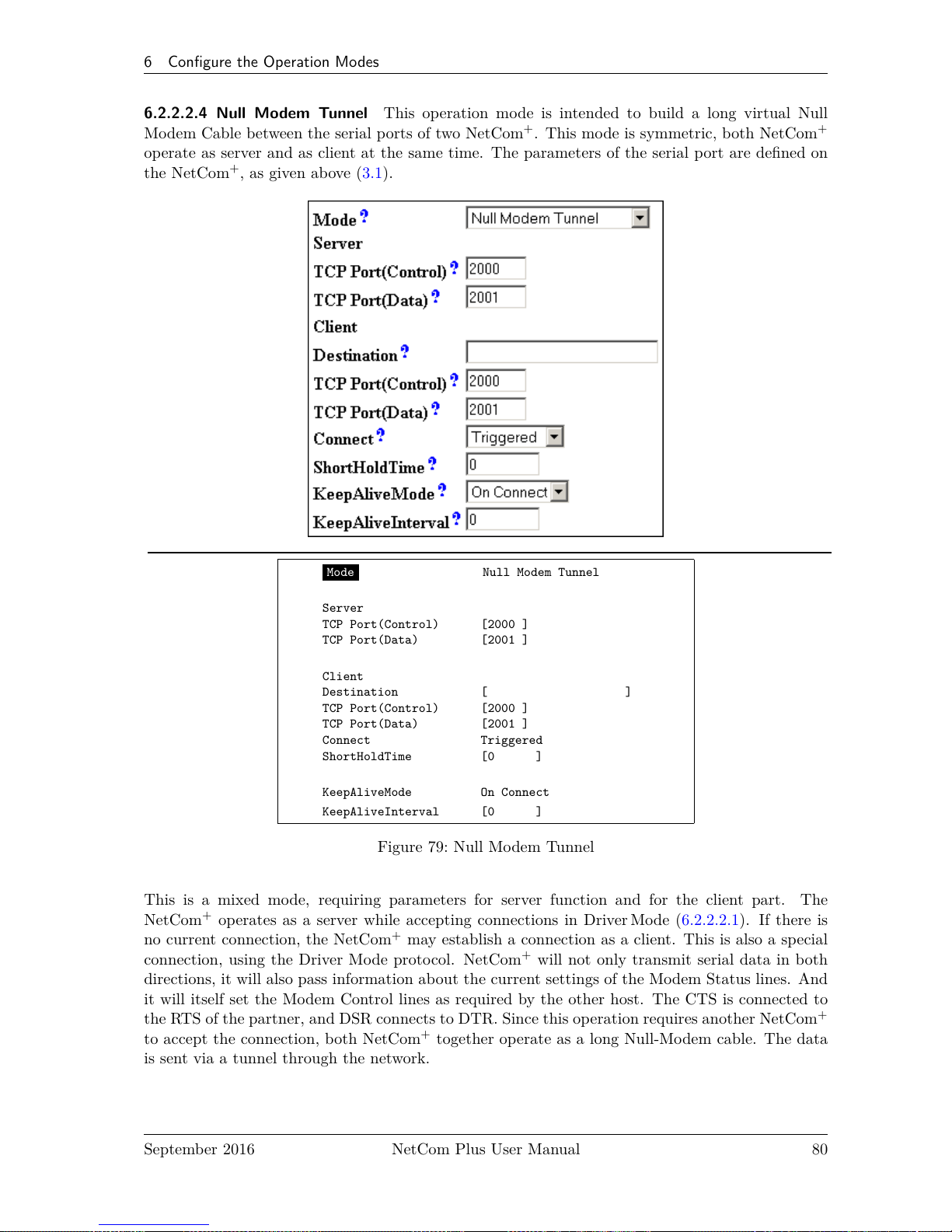
6 Configure the Operation Modes
6.2.2.2.4 Null Modem Tunnel This operation mode is intended to build a long virtual Null
Modem Cable between the serial ports of two NetCom+. This mode is symmetric, both NetCom
+
operate as server and as client at the same time. The parameters of the serial port are defined on
the NetCom+, as given above (3.1).
Mode Null Modem Tunnel
Server
TCP Port(Control) [2000 ]
TCP Port(Data) [2001 ]
Client
Destination [ ]
TCP Port(Control) [2000 ]
TCP Port(Data) [2001 ]
Connect Triggered
ShortHoldTime [0 ]
KeepAliveMode On Connect
KeepAliveInterval [0 ]
Figure 79: Null Modem Tunnel
This is a mixed mode, requiring parameters for server function and for the client part. The
NetCom+operates as a server while accepting connections in DriverMode (6.2.2.2.1). If there is
no current connection, the NetCom+may establish a connection as a client. This is also a special
connection, using the Driver Mode protocol. NetCom+will not only transmit serial data in both
directions, it will also pass information about the current settings of the Modem Status lines. And
it will itself set the Modem Control lines as required by the other host. The CTS is connected to
the RTS of the partner, and DSR connects to DTR. Since this operation requires another NetCom
+
to accept the connection, both NetCom+together operate as a long Null-Modem cable. The data
is sent via a tunnel through the network.
September 2016 NetCom Plus User Manual 80
Page 81

6 Configure the Operation Modes
The configuration as Server (top part) requires the same parameters as the Driver Mode, hence
TCP Port(Control) and TCP Port(Data). Also the KeepAlive function operates the same.
The configuration as Client (bottom) first requires a destination. Here it is given by name, but a
direct IP Address may be more usual. On the destination there is also a TCP Port(Control) and
TCP Port(Data) to accept the connect of the NetCom+.
The Connect methods are the same as with the TCPRaw Client mode. So connections to the
partners are permanent, last until there is no activity for a given time, or they are controlled by
the DSR signal.
Attention: You must not configure both NetCom+with a Connect option configured as Permanent.
This will result in each of them attempting to contact the other at the same time. Both NetCom
+
will reject the connect, because they are already busy establishing a connect of their own. Instead
create an asymmetric configuration: either use one of the NetCom+in Driver Mode, or configure
it with an empty Destination parameter. Or consider to have a connection on demand, i.e. use the
Triggered option.
September 2016 NetCom Plus User Manual 81
Page 82

6 Configure the Operation Modes
6.2.2.2.5 TCP Advanced Settings All of the above operation modes are special configurations
for options. In some situations none of the pre-defined modes fit the customers needs. When this
is the case, the TCP Advanced Settings offer the configuration of any Transfer parameter. Unusual
combinations of Modes are possible with this, also standard modes with unusual parameters.
Transfer Settings
Port Nr. 1
Mode TCP Advanced Settings
Server On
TCP Port(Control) [2000 ]
TCP Port(Data) [2001 ]
Max.Clients [1 ]
Client Off
Destination [ ]
TCP Port(Control) [2000 ]
TCP Port(Data) [2001 ]
Connect Triggered
ShortHoldTime [0 ]
KeepAliveMode On Connect
KeepAliveInterval [0 ]
Figure 80: TCP Advanced Settings
The NetCom+usually acts as a network server. This means it accepts incoming connections. The
most used Driver Mode is one example. The NetCom+detects which mode to use. When the
Data-Port is opened first, then the NetCom+operates in TCP Raw Server mode, with respect to
Max.Client. When the Control-Port is opened first, the NetCom+expects a second connection on
the Data port, to operate in Driver Mode for one client only.
September 2016 NetCom Plus User Manual 82
Page 83

6 Configure the Operation Modes
The NetCom+can also operate as a network client as seen in TCPRaw Client mode. This is
enabled by setting Client to On. As a client it requires the same parameter as for the specialized
modes. When the TCP Port(Control) is defined (not zero), the NetCom+will operate as a client
for Driver Mode, as in Null Modem Tunnel. The destination is the target address or DNS name.
Otherwise the NetCom+operates in TCP Raw Client mode when it establishes a connection. The
syntax for multiple destinations applies then.
The remaining parameters are explained in the client mode descriptions.
The TCP Advanced Settings allow for flexible usage of the NetCom+, when Server and Client
modes are On at the same time. If no connection is active with the NetCom+, it accepts incoming
connections, i.e. it operates as server as long as the connections are held. Without a connection
a Trigger event defined in Connect cause the NetCom+to establish a connection to the defined
target. So the NetCom+is a client at that time.
6.2.2.2.6 UDP Data Transfer UDP is an Internet Protocol, which does not define a connection,
it sends data in single packets instead of a stream. There is no extra return data to signal a
successful transmission. As a side effect data may be sent and received faster than with TCP/IP.
Mode UDP Mode
UDP Port(Local) [2002 ]
Destination [ ]
UDP Port(Dest) [2002 ]
UDP MaxPacketSize [1458 ]
UDP Timeout [30 ]
UDP Trigger [ ]
Figure 81: UDP Data Transfer
This protocol requires a UDP Port(local) for listening to incoming data. Other stations on the
network send their data to this port. The Destination host is configured by IP Address or name,
plus the target UDP Port(Dest). Please compare with the parameters for TCP Raw Server and
Client Modes. The parameters to configure the UDP Mode are similar to a mixture of these modes.
A UDP Broadcast is sent, if the destination address is the broadcast Address, see section 6.2.1.2
above.
September 2016 NetCom Plus User Manual 83
Page 84

6 Configure the Operation Modes
Since there is no connection, data can not be sent in a stream. UDP uses packages. There are
several ways to define the content for a package.
UDP MaxPacketSize is a limit for the size of UDP packets. When the amount of data received on the
serial port reaches this limit, the UDP Frame is assembled and sent to the destination.
UDP Timeout defines when the NetCom+sends the received data as a UDP Frame. If the reception
of serial data is interrupted for this time (in milliseconds), the data sampled so far is
sent to the destination. A value of zero causes all data to be sent immediately, use
“-1” to disable the function of timeout trigger. A good value to start with is 30, if no
specific parameters are given by the external devices. This is the default since fimrware
version 3.3.5
UDP Trigger defines a sequence of characters. As soon as this sequence is detected in the received
data, all data up to the end of this Trigger is sent to the destination. In most situations
such a Trigger includes control or other special characters. Enter them numeric: as
\xHH where HH is the hexadecadic code of the character, or as \OOO where OOO is
the octal code of the character. The backslash itself must be doubled as \\.
If none of these options is used, the packets definition is not specified. This will result in unpre-
dictable separation of serial data, depending on internal hardware behaviour. Typically this is not
handled good by the application software.
6.2.2.2.7 IP-Modem The serial port of a NetCom+may mimic (emulate) a serial modem. There
is the separate section 8 defining this functionality. Here are the basic network parameters only.
Mode IP Modem
TCP Port(Data) [2001 ]
Destination [ ]
IP Modem Config [ ]
Figure 82: IP-Modem
A serial modem accepts connections from a phone line, while an IP Modem accepts connections
from the network, in this case via TCP/IP. The TCP port for this is defined as the TCP Port(Data),
similar to TCP Raw Server mode. This is the only parameter required to set here.
All other values are normally defined by AT-commands via the serial port. However for short,
Destination allows for up to four predefined targets, available with special Dial commands. The
IP Modem Config is known as the Init String in standard modems.
September 2016 NetCom Plus User Manual 84
Page 85

6 Configure the Operation Modes
6.2.2.2.8 Print Server Function The NetCom+firmware allows the function as a Print Server
according to RFC1179, also called a »Line printer daemon«. A print server is accessed through
its IP Address via one specified TCP Port (see section 6.2.1.2). Data is handled in distinct queues,
each with a certain name. Each queue is handled by a certain serial port, and the data is sent to
the serial printer attached to this port.
Port Nr. 1
Mode Print Server
QueueName [lpd1 ]
InitString [ ]
Figure 83: Print Server Configuration
Each serial port configured for Print Server operation has its separate QueueName. The default
value is »lpd« plus port number. The InitString is a special feature of NetCom+. This string
is sent to the serial printer at the beginning of the next queued print job. The definition is in
section 9.2.1 on page 105.
6.2.2.3 Save
Web: menu “SERIAL CONFIGURATION”, at bottom.
Again at the bottom of the web page below all the serial port options there is the button Save.
This will store all configurations done for the current group of serial ports. Selecting a different
group of ports or another configuration section from the menu may discard all changes done.
6.2.3 NetCom Tools
Several tools for system status, checks and debugging are available in the Firmware. The available
tools are:
• The Ping utility to check if a station is available.
• Statistic information for each serial port.
• The Netstat utility to monitor used TCP connections.
• The option to detect WLAN devices in the proximity (NetCom Plus with WLAN option
only)
• The option to update the firmware.
September 2016 NetCom Plus User Manual 85
Page 86

6 Configure the Operation Modes
• Saving of Configuration to / Loading from a file (web browser only).
• Information logging by Syslog function and a DebugLog via TCP/IP.
In your web browser click on the Icon of “TOOLS”, the browser opens the list of available tools.
In Telnet the “Tools” menu provides a list of the tools.
6.2.3.1 Ping
Web: menu “Tools”, section “Ping”.
Telnet: “Tools”, option “Ping”.
Enter the IP Address or the name of a station in the field. In the web browser click the Ping
button, hit the <Enter>-key via Telnet. The network connection is checked by sending ICMP
Echo Request data packages.
PING 127.0.0.1 from 192.168.1.87 : 44 (72) bytes of data
52 bytes from 127.0.0.1: icmp_seq=0 ttl=255 time=1.560 msec
52 bytes from 127.0.0.1: icmp_seq=0 ttl=255 time=1.542 msec
52 bytes from 127.0.0.1: icmp_seq=0 ttl=255 time=1.542 msec
back
Figure 84: Ping and Response in Web Browser
Tools
+-------------+
| Ping |
| Statistic |
| Netstat |
| Wireless |
| Logging |
| Firmware |
+-------------+
IP-Address to ping to: [127.0.0.1 ]
PING 127.0.0.1 from 192.168.1.243 : 44 (72) bytes of data.
52 bytes from 127.0.0.1: icmp_seq=0 ttl=64 time=< 10 ms
52 bytes from 127.0.0.1: icmp_seq=1 ttl=64 time=< 10 ms
52 bytes from 127.0.0.1: icmp_seq=2 ttl=64 time=< 10 ms
52 bytes from 127.0.0.1: icmp_seq=3 ttl=64 time=< 10 ms
Figure 85: Ping and Response in Telnet
If the target responds, the network between the NetCom+and the target is operational. The time
required for an echo depends on the speed of the network. In a typical Ethernet this is only very
few Milliseconds, while it can be several seconds throughout the Internet.
September 2016 NetCom Plus User Manual 86
Page 87

6 Configure the Operation Modes
Via Telnet use the <Esc>-key to stop the Ping function.
6.2.3.2 Statistics
Web: menu “Tools”, section “Statistics”.
Telnet: “Tools”, option “Statistics”.
The Statistics are presented on a by-port base. So you first select the serial port, and then you get
the information about modem status and control. Also the amount of data transferred is shown.
Tools
+-------------+
| Ping |
| Statistic |
| Netstat |
| Wireless |
| Logging |
| Firmware |
+-------------+
Tools
+----------+
| Port 1 |
| Port 2 |
| Port 3 |
| Port 4 |
+----------+
Figure 86: Statistics Port Selection
Line Status
DTR off (0)
DSR off (0)
RTS off (0)
CTS off (0)
DCD off (0)
RI off (0)
Common
Serial Tx 0
Serial Rx 0
Figure 87: Port Statistics
The statistics window9reports the state of the modem status and control signals. Further the
NetCom+counts the number of status changes on the modem control- and status-signals, since the
NetCom+has been started. The number of characters sent and received is shown at the bottom.
9
The web browser opens a separate window for each port selected
September 2016 NetCom Plus User Manual 87
Page 88

6 Configure the Operation Modes
6.2.3.3 Netstat
Web: menu “Tools”, section “Netstat”.
Telnet: “Tools”, option “Netstat”.
Tools
+-------------+
| Ping |
| Statistic |
| Netstat |
| Wireless |
| Logging |
| Firmware |
+-------------+
Figure 88: Start Netstat
Update
Proto Local Address Foreign Address State
tcp 0.0.0.0:23 0.0.0.0:0 LISTEN
tcp 0.0.0.0:80 0.0.0.0:0 LISTEN
tcp 0.0.0.0:2000 0.0.0.0:0 LISTEN
tcp 0.0.0.0:2001 0.0.0.0:0 LISTEN
tcp 0.0.0.0:2010 0.0.0.0:0 LISTEN
tcp 0.0.0.0:2011 0.0.0.0:0 LISTEN
tcp 0.0.0.0:2020 0.0.0.0:0 LISTEN
tcp 0.0.0.0:2021 0.0.0.0:0 LISTEN
tcp 0.0.0.0:2030 0.0.0.0:0 LISTEN
tcp 0.0.0.0:2031 0.0.0.0:0 LISTEN
tcp 192.168.1.243:80 192.168.1.42:1280 TIMEWAIT
tcp 192.168.1.243:80 192.168.1.42:1281 ESTABLISHED
udp 0.0.0.0:161
udp 0.0.0.0:19970
udp 192.168.1.243:32331
(a) In Web Interface
1/1
Proto Local Address Foreign Address State
tcp 0.0.0.0:23 0.0.0.0:0 LISTEN
tcp 0.0.0.0:80 0.0.0.0:0 LISTEN
tcp 0.0.0.0:2000 0.0.0.0:0 LISTEN
tcp 0.0.0.0:2001 0.0.0.0:0 LISTEN
tcp 0.0.0.0:2010 0.0.0.0:0 LISTEN
tcp 0.0.0.0:2011 0.0.0.0:0 LISTEN
tcp 0.0.0.0:2020 0.0.0.0:0 LISTEN
tcp 0.0.0.0:2021 0.0.0.0:0 LISTEN
tcp 0.0.0.0:2030 0.0.0.0:0 LISTEN
tcp 0.0.0.0:2031 0.0.0.0:0 LISTEN
tcp 192.168.1.98:23 192.168.1.42:3665 ESTABLISHED
udp 0.0.0.0:161
udp 0.0.0.0:33320
udp 192.168.1.98:10397
(b) In Telnet
Figure 89: Netstat Sample Output
September 2016 NetCom Plus User Manual 88
Page 89

6 Configure the Operation Modes
Netstat is a common tool to display the actual status of network connections. It may be used to
monitor the actual status of the NetCom+. This is a standard tool for network debugging.
A ‘Foreign Address’ of “0.0.0.0” is listed when NetCom+is waiting for an incoming connection
(LISTEN mode). If the value is not “0.0.0.0”, the connection is either active (ESTABLISHED) or
already closed (TIMEWAIT).
In the web browser you may Update the Netstat output.
Via Telnet the output may not fit on the screen, then the display will start with “1/2" in the first
line. Or even more for a long list. You may change to a different page by using the Page Up/Down
keys in your Telnet. The display is refreshed in an interval of some seconds. Use <Esc>-key to
return to the menu.
6.2.3.4 Wireless
Web: menu “Tools”, section “Wireless”.
Telnet: “Tools”, option “Wireless”.
When Wireless communications is intended, it is useful to see a list of possible partner stations
on the WLAN. This function is available in many driver packages for Windows, and also in the
NetCom Plus with WLAN option Serial Device Servers. This detection is often referred to as
»Range Scan«.
Tools
+-------------+
| Ping |
| Statistic |
| Netstat |
| Wireless |
| Logging |
| Firmware |
+-------------+
Figure 90: WLAN Scan
On the NetCom Plus with WLAN option it will open a separate browser window with the results.
An example of this is shown below. Telnet displays the results.
Wireless-Devices in Range Update
Act MAC SSID Channel Mode Enc
X 86:73:F6:22:E1:BA NetCom_0210100462 7 Ad-Hoc
X A6:E8:9E:BE:7D:86 NetCom_0210100444 7 Ad-Hoc
X 00:0F:B5:66:CF:56 NETGEAR 11 Managed X
Current Rate: 11Mb/s
Act MAC SSID Ch Mode Enc
X 86:73:F6:22:E1:BA NetCom_0210100444 7 Ad-Hoc
A6:E8:9E:BE:7D:86 NetCom_0230100152 7 Ad-Hoc
X 00:0F:B5:66:CF:56 NETGEAR 11 Managed X
Current Rate: 11Mb/s
Figure 91: WLAN Scan Output
September 2016 NetCom Plus User Manual 89
Page 90

6 Configure the Operation Modes
This example lists two other NetCom configured for Ad-Hoc communication on channel 7. Both do
not use encryption. There is also an Access Point (listed as Managed), of course in Infrastructure-
mode. To connect to this AP the NetCom Plus with WLAN option must use encryption.
In Telnet the display is updated automatically when some information changes. Most noticeably
this will be the Act-ivity sign.
6.2.3.5 Firmware
Web: menu “Tools”, section “FirmwareUpdate”.
Telnet: “Tools”, option “Firmware”.
To upload a new version of the firmware, put the name of the file in the field. Your web browser
will allow to search for the file. Click on the Update button, and your browser will upload the file
to the NetCom+.
Tools
+-------------+
| Ping |
| Statistic |
| Netstat |
| Wireless |
| Logging |
| Firmware |
+-------------+
Firmware Update
Update Port [2400 ]
[ Start Update ]
Figure 92: Firmware Upload
Via Telnet the option to upgrade the Firmware of NetCom+is different. The upload of the data
is either done via the current channel (i.e. the serial or Telnet connection). Or independently
via a separate TCP/IP connection. The Update Port parameter defines this second connection,
the NetCom+waits for a TCP connection on this port. The Firmware is sent coded in base64
(a special text format), via very simple programs like a second Telnet session, or similar tools.
Terminal software by serial configuration may just use the “Send Textfile” function.
While uploading the file it is checked by NetCom+. If it is a valid content, it is stored in the Flash
Memory. When the upload is finished, NetCom+will Reboot.
September 2016 NetCom Plus User Manual 90
Page 91

6 Configure the Operation Modes
6.2.3.6 Save and Load Configuration
Web: menu “Tools”, section “Configuration File”.
Via web browser it is possible to save the actual configuration to a text file. Of course it is also
possible to load the saved configuration into a NetCom+.
Figure 93: Save and Load Configuration in Web Browser
This may be very useful when configuring several NetCom+of the same type. Configure one
device, and save the file. Change the configuration file for the necessary parameters, and upload
the modified version to the next model.
6.2.3.7 Logging and Debug
Web: menu “Tools”, section “Syslogging”.
Telnet: “Tools”, option “Logging”.
The NetCom+has two options of Logging. There is the standard Syslog, and a second option of
logging via Telnet.
Tools
+-------------+
| Ping |
| Statistic |
| Netstat |
| Wireless |
| Logging |
| Firmware |
+-------------+
Logging
Syslog Off
Destination [ ]
Facility [1 ]
Debuglog Off
Debug Port [0 ]
Figure 94: Syslog & Debuglog Parameters
September 2016 NetCom Plus User Manual 91
Page 92

6 Configure the Operation Modes
The Syslog function may of course be Off or On. In the On-state the NetCom+sends all the log
information to a computer defined by Destination. A special software often called Syslog Daemon
has to receive these data. The Option of Facility is a criteria for the Daemon how this will
organize the data received from the NetCom+.
In contrast for Debuglog the NetCom+behaves as the server. When this option is On the NetCom
+
waits for incoming TCP connections to the configured Debug Port. The NetCom+sends all logging
information via this connection. For manual use a software like Telnet is suitable, especially if it
has the option to save all received data.
6.2.3.8 Save
Web: menu “Tools”, at bottom.
As usual at the bottom of the web page below all the options there is the button Save. This will
store the configurations done for Logging (6.2.3.7).
6.2.4 Reboot
Web: menu “REBOOT”.
In your web browser, click the Icon of REBOOT to restart the NetCom+firmware.
Attention: This option will discard all configuration changes, unless they have explicitly been saved.
Naturally it will also disconnect all other clients using serial ports or the Telnet configuration
menu.
6.2.5 Save&Exit Menu
This section of configuration is only available via the terminal interface, i.e. via Telnet or serial
port. Modifications in the configuration of the NetCom+are not active, until they are explicitly
saved to the Flash Memory of NetCom+. This menu also allows to discard all changes, and even
to restart the firmware.
6.2.5.1 Save Parameter
Telnet: “Save&Exit”, option “Save Parameter”.
When some changes are done, these modified settings should be saved. A confirmation is requested
before doing this.
Save&Exit
+------------------+
| Save Parameter |
| Exit |
| Reboot |
+------------------+
+---------------------------------+
| Do you want to save the changes |
| Yes No |
+---------------------------------+
Figure 95: Menu Save modified Parameters in Telnet
The Telnet interface is still active when this operation is finished.
September 2016 NetCom Plus User Manual 92
Page 93

6 Configure the Operation Modes
6.2.5.2 Exit
Telnet: “Save&Exit”, option “Exit”.
You will not be surprised, when you leave the menu by selecting this option. If you made any
changes of parameters, you must confirm to save these.
Save&Exit
+------------------+
| Save Parameter |
| Exit |
| Reboot |
+------------------+
+---------------------------------+
| Do you want to save the changes |
| Yes No |
+---------------------------------+
Figure 96: Menu Exit from Configuration in Telnet
The NetCom+terminates the Telnet interface when this operation is finished, even when the
modifications are not saved to Flash Memory.
6.2.5.3 Reboot
Telnet: “Save&Exit”, option “Reboot”.
Users may restart the firmware of the NetCom+. Modified configurations are activated by the
restart process. Such a restart is necessary for some changes like IP configuration, others do not
require a restart.
Save&Exit
+------------------+
| Save Parameter |
| Exit |
| Reboot |
+------------------+
+---------------------------------+
| Do you want to save the changes |
| Yes No |
+---------------------------------+
Figure 97: Exit and Reboot in Telnet
Also here, if parameters are changed during the session, confirmation for saving them is requested.
Of course the Telnet configuration is closed, because all TCP connections are terminated by the
reboot process.
6.3 Erase Configuration of NetCom
Sometimes it is required to clear any configuration done, and go back to the Factory Settings. Users
might think this is possible with the Reset button. It is not done this way. The Reset button is
just a way to restart the NetCom+without removing the power.
To make a clean configuration the DIP switches must be configured to the pattern of »Fac-
tory settings«. Refer to Section 3.1 or to the table on top of the NetCom+case. When this pattern
is chosen, the NetCom+has to be restarted, by power off or by using the Reset button. This is for
security. When changing a DIP configuration, the »Factory settings« might appear by accident.
So the NetCom+requires to be restarted with this DIP pattern active to avoid accidental damage
of the configuration. While restarting, the NetCom+erases the current configuration, and replaces
September 2016 NetCom Plus User Manual 93
Page 94

7 Operation in Linux
the parameter with the default values. When this is finished, the Power LED blinks once. Do not
power off or reset the NetCom+before this blink is seen.
The Ethernet cable should not be connected, because the NetCom+uses DHCP in factory config-
uration. Without an Ethernet cable it does not attempt to find a DHCP server, which makes for
a faster reboot process.
7 Operation in Linux
In Linux there is no real tty driver available for NetCom Plus serial device servers. However for most
applications this is not a problem, since Linux is very good in networking. Either the application
can contact the Serial Port on the NetCom+via a TCP connection, or it may use a fixed tty
emulation of a serial port. In both configurations the parameters of the serial port are configured
on the NetCom+. Additionally the serial port is operating in the mode of TCP Raw Server, with
one defined TCP port to connect to (see 6.2.2.1 on page 74 and 6.2.2.2.2 on page 78 for details).
For the following sections the IP Address 192.168.1.198 is used, with 2001 as the TCP data port
number. This may be the serial port of a NetCom Plus 113 serial device server.
7.1 Via Fixed TTY Pseudo Serial Port (socat)
There are applications designed to operate via serial ports, and via this only. So they want to open
a device which behaves like a serial port, usually /dev/ttyS0 or /dev/modem. To create a pseudo
device of this type the program socat may be used.
so c a t pty , l i n k =/dev /netcom0 , raw , wa i t s l a v e t cp : 1 9 2 . 1 6 8 . 1 . 2 4 9 : 2 0 0 1&
This command creates a temporary pseudo tty device with the name as /dev/netcom0. Any name
is possible, as long as it does not conflict with already existing devices. The TCP connection will
be established to the serial port on NetCom+, but this is delayed until an application opens this
/dev/netcom0. The connection will be established as raw (without modifying data).
The terminating ’&’ in the line sends socat into background operation. It will terminate when
/dev/netcom0 is closed by the application.
minicom −D /dev / netcom0
This command will then start the application minicom as an example. In this example the created
/dev/netcom0 is used, so minicom operates via the serial port on the NetCom+. Even when
minicom attempts to configure the serial port, this has no effect on the NetCom+. When minicom
is closed, the process of socat terminates as well. For next use socat must be started again, which
can be done in a script also.
The specification as “Fixed TTY” defines that behavior. Applications may use the pseudo port
like a serial port, but the serial configuration is fixed. Any commands to change the configuration
are accepted from the application, but they do not change the serial port operation.
September 2016 NetCom Plus User Manual 94
Page 95
7 Operation in Linux
7.2 Via TCP Raw Server Mode
The application will use the IP Address of the NetCom+with the configured TCP port number for
the intended serial port. Usually the first serial port uses 2001 as TCP data port, so as an example
program here is the command line for telnet application:
t e l n e t 1 9 2 . 1 6 8 . 1 . 2 4 9 2001
This command will open a raw TCP connection to the NetCom+. This connection is raw (no
modification of data) because there is no initiation of the protocol known as Telnet (RFC 854).
Every byte received on the serial port is displayed on the screen. And all characters typed on the
keyboard are sent via the serial port to the connected device. The serial parameters used are stored
in the NetCom+, e.g. 38400,8,n,1 without flow control. If RTS/CTS or a different mode of flow
control is configured, this is handled internally at the serial port inside the NetCom+.
Especially with telnet users often get confused by doubled characters on the screen. This is caused
by a misconfiguration of telnet, in this case the option of local echo. The typed character is shown
on the screen by telnet, and the serial device also sends back the character. The configuration of
telnet is beyond the scope of this manual.
Telnet is one example, other applications will use their own methods of configuation.
September 2016 NetCom Plus User Manual 95
Page 96

8 IP Modem Function
8 IP Modem Function
The Firmware offers the function of IP Modem. Used in this mode, the serial port of the NetCom
+
emulates a standard serial modem. Basically this means the NetCom+will
a) answer to AT-commands on the serial port
b) establish a connection to a destination
c) inform the connected serial device of the connection
d) accept a TCP connection, and inform the serial device of that event
For connections the NetCom+will use a TCP connection. This differs from a normal telephone
line, so there will be some modifications in the behavior. The target is an IP Address, not a phone
number. Also for hardware reasons the automatic baudrate detection used in today serial Modems
is not available. However this is not a problem at all, the IP Modem can be installed in Windows
as a Standard 33600bps Modem. There is an INF-file for ease of installation.
8.1 Some possible Scenarios
1. The customer has a remote management installation, operating via telephone line. These
lines may be in-house or through public phone systems to other destinations. The customer
wants to reduce costs for these lines, management and possibly hardware, using the Intra- or
Internet.
2. The customer wants to contact several stations from a central server. Because of frequent
target changes he does not want to define the target by a Virtual Com Port.
3. Remotely distributed devices contact a central system by Modem. This is the reverse of
option 1.
4. A computer without Network access shall have at least limited control on the connections
established by a NetCom+.
5. Old fashioned BBS installations become accessible via Internet. The typical multi-modem
box is replaced by a NetCom+Server with multiple ports configured for IP Modem operation.
8.2 Serial Signals and Cables
A real modem provides the same signals as the serial port of a PC. However, where a signal is an
output on the PC, it is an input to the modem, and vice versa. So in the NetCom+the emulation
of a modem must be incomplete. By exchanging RxD and TxD the data connection is fine, the
same happens for handshaking signals RTS and CTS. The DTR of the PC is connected to DSR of
NetCom+, this is simple. The RI may be ignored, some connectors for serial ports also do that.
However a real modem provides DSR and DCD to the PC. There is only the DTR left on NetCom
+
to serve these signals. In most configurations the NetCom+-DTR serves as the DCD to the com-
puter.
The cable must provide a DSR to the PC then, e.g. by shortcut to the PC-DTR. In some configu-
rations the NetCom+-DTR must serve as the DSR. This is configurable by a command.
September 2016 NetCom Plus User Manual 96
Page 97

8 IP Modem Function
The recommended cable connects as shown in this table. Please note, this installation does not
use the simply crossed signals. Especially the DSR of the PC is internally connected to the DTR
of the PC.
DB9m PC IP-Modem DB9m DB9f
3 TxD —— RxD 2 3
2 RxD —— TxD 3 2
7 RTS —— CTS 8 7
8 CTS —— RTS 7 8
6 DSR PC-DTR (internal loop-back)
4 DTR —— DSR 6 4
1 DCD —— DTR 4 6
5 GND —— GND 5 5
Table 19: IP Modem cable
The limitation of signals is a restriction in function, compared to real world serial modems. Since
most installations do not require the full availability of all signals, the required subset can be
selected.
8.3 Operation Modes by IP Modem
The function of IP-Modem may be configured port by port. On a NetCom+with a single port
there is no much of a difference. However a NetCom+with more serial ports operates each port
independently. In the following sections of this manual the phrase "serial port of a NetCom+,
configured to operate as IP Modem" is replaced by "IP Modem" for brevity.
Two basic operation modes are available. The first and default mode is Modem-to-Modem. This
requires a serial port of a NetCom+configured as IP Modem on both ends of the connection.
When one IP Modem dials the other, the connection is established on the TCP level. Directly
afterward both IP Modems negotiate to ensure they are a real NetCom+IP Modem and are free
for connection. If successful both issue a "CONNECT . . . " response to the serial connected devices.
This is convenient for the customer to understand. The CONNECT may report some parameters,
e.g. the minimum serial speed used by both Modems. These extra parameters are not implemented
so far.
The other mode is named as Modem-to-Host. The destination is any software, which opens a TCP
port for Listen mode. It may be a second NetCom+configured for TCP Raw Server Mode. It may
also be the customers application, running on a certain computer. This mode offers less features.
8.4 Hayes Commands
The IP Modem operates with a command set similar to those in real Modems. All of the commands
start with the character sequence AT.
September 2016 NetCom Plus User Manual 97
Page 98

8 IP Modem Function
8.4.1 AT command set
The following table lists many standard commands (in alphabetical order). The AT is omitted for
brevity. The discussion of the functions is below the tables in section 8.5 below.
8.4.1.1 Standard AT-Commands These commands are based on the old Hayes Modem.
AT Hayes-Standard IP Modem Function
A Answer Call Accept a connection
Bn ITU-T modulation Define some modem operation modes
Dnnn Dial connection, basically phone
number as nnn
Connect to the target system by
IP Address and TCP-Port. E.g.
ATD10,0,8,42,2023 will "dial" to port
2023 on IP Address 10.0.8.42
E Echo on/off Enable/Disable local echo of command
H0 Hang up Terminate the TCP connection
I Device Information I0 through I9 report information
L Speaker Volume Ignored, always answered with OK
M Speaker On/Off Ignored, always answered with OK
N Auto serial speed N0 no Auto, N1 reports error
O Return to data mode
Q Result Codes Enable or disable result codes/strings
S=nn/S? S-Register Set/request configuration registers
V0/1 Responses Numeric/text responses to commands
X Busy/Dial detect Ignored, always answered with OK
Z Reset to User profile Standard
Table 20: IP Modem Standard AT-Commands
8.4.1.2 Extended AT-Commands These commands are used in modern modems, and have slightly
different syntax depending on the model.
AT Standard-Extensions IP Modem Function
&C DCD control When to turn on DCD (by IP Modems DTR)
&D DTR meaning Hang Up, Command Mode or Reset
&F Load factory Default
&K Flow Control
&S DSR control When to turn on DSR (by IP Modems DTR)
&V View Profiles
&W Store Profile &W0/&W1 is "Standard". ATZ1 loads profile 1
&Zn=dd Save for short dial Define possible targets by DNS name or IP Address
%C1 V.42bis enable Ignored
\Q Flow control See &K
Table 21: IP Modem Extended AT-Commands
September 2016 NetCom Plus User Manual 98
Page 99
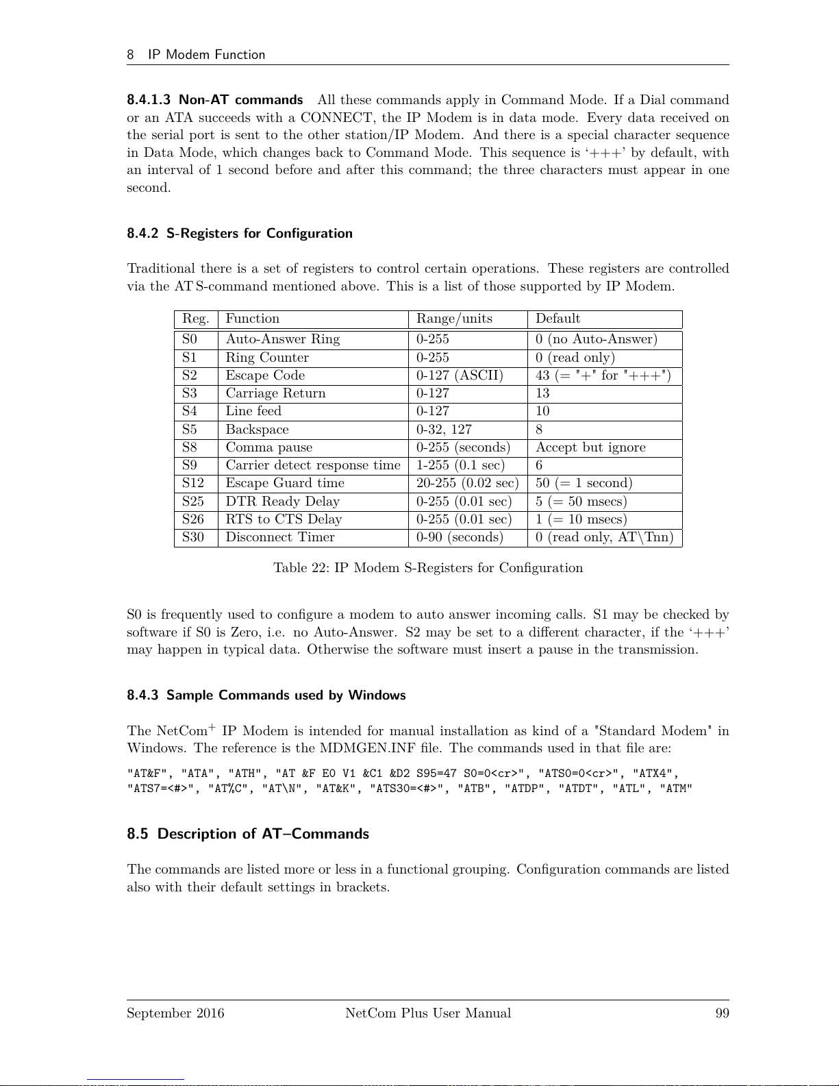
8 IP Modem Function
8.4.1.3 Non-AT commands All these commands apply in Command Mode. If a Dial command
or an ATA succeeds with a CONNECT, the IP Modem is in data mode. Every data received on
the serial port is sent to the other station/IP Modem. And there is a special character sequence
in Data Mode, which changes back to Command Mode. This sequence is ‘+++’ by default, with
an interval of 1 second before and after this command; the three characters must appear in one
second.
8.4.2 S-Registers for Configuration
Traditional there is a set of registers to control certain operations. These registers are controlled
via the AT S-command mentioned above. This is a list of those supported by IP Modem.
Reg. Function Range/units Default
S0 Auto-Answer Ring 0-255 0 (no Auto-Answer)
S1 Ring Counter 0-255 0 (read only)
S2 Escape Code 0-127 (ASCII) 43 (= "+" for "+++")
S3 Carriage Return 0-127 13
S4 Line feed 0-127 10
S5 Backspace 0-32, 127 8
S8 Comma pause 0-255 (seconds) Accept but ignore
S9 Carrier detect response time 1-255 (0.1 sec) 6
S12 Escape Guard time 20-255 (0.02 sec) 50 (= 1 second)
S25 DTR Ready Delay 0-255 (0.01 sec) 5 (= 50 msecs)
S26 RTS to CTS Delay 0-255 (0.01 sec) 1 (= 10 msecs)
S30 Disconnect Timer 0-90 (seconds) 0 (read only, AT\Tnn)
Table 22: IP Modem S-Registers for Configuration
S0 is frequently used to configure a modem to auto answer incoming calls. S1 may be checked by
software if S0 is Zero, i.e. no Auto-Answer. S2 may be set to a different character, if the ‘+++’
may happen in typical data. Otherwise the software must insert a pause in the transmission.
8.4.3 Sample Commands used by Windows
The NetCom+IP Modem is intended for manual installation as kind of a "Standard Modem" in
Windows. The reference is the MDMGEN.INF file. The commands used in that file are:
"AT&F", "ATA", "ATH", "AT &F E0 V1 &C1 &D2 S95=47 S0=0<cr>", "ATS0=0<cr>", "ATX4",
"ATS7=<#>", "AT%C", "AT\N", "AT&K", "ATS30=<#>", "ATB", "ATDP", "ATDT", "ATL", "ATM"
8.5 Description of AT–Commands
The commands are listed more or less in a functional grouping. Configuration commands are listed
also with their default settings in brackets.
September 2016 NetCom Plus User Manual 99
Page 100

8 IP Modem Function
8.5.1 AT D (dial)
This is the general Dial command. The target is defined as IP Address plus TCP-port number. The
dots in the address are replaced by a comma, and the TCP port is also separated by a comma. On
normal modems a comma generates a pause in the dialing sequence. This is commonly required,
so all software will support it; even multiple comma.
The modifiers ‘T’ for Touch Tone and ‘P’ for Pulse dialing have no direct equivalent on the TCP
connection. They are used to change between Modem and Host mode, if the ATB command enables
this (ATB2 or ATB3). Otherwise the IP Modem will ignore them.
Basically dialing is done to a given IP Address plus a TCP port number. The IP Address is given in
decimal Octet format, where comma replaces the dot as the separator. This is followed by another
comma, separating the TCP Port from the IP Address. If the port is omitted, the target port is
the same as the local TCP Data Port as defined in the configuration of IP Modem (see 6.2.2.2.7
above).
There are situations where the target is known by a DNS name. This name can not be used in a
dial string, mostly because very few software will support it. So there is the option of dialing to a
pre-defined entry by shortcut. This is given by an ‘S’ followed by one or two digits. The shortcuts
S90 to S99 are reserved; so far only S1 to S4 are implemented. Shortcuts are defined and saved by
‘AT&Znn=<FDN:Port>’.
All other non-numeric characters are understood as modifiers. The IP Modem will simply ignore
them. This especially applies to space characters. Typically dial strings are:
ATDT192,168,254,254,2003<cr> Dial another IP Modem as a Modem-to-Modem
AT&Z12=demokit.vscom.com.tw:23<cr> Define a shortcut for configuration port
ATDPS12<cr> Dial the other IP Modem as Modem-to-Host
Table 23: IP Modem Sample Dials
8.5.2 AT O (online / data mode)
If a connection is established, the IP Modem can still be in command mode. The ATO activates
the transparent data mode.
8.5.3 AT A (answer call)
Have the IP Modem answer an incoming call, and establish a TCP connection. This command is
required if Auto-Answer is disabled. Observe the operation mode defined by ATB.
8.5.4 AT B (modulation) [ATB1]
This command is used to define the modulation to use on the phone line. Since the only "modula-
tion" available is IP, there is no choice. The command is used to change between Modem-to-Modem
and Modem-to-Host mode.
September 2016 NetCom Plus User Manual 100
 Loading...