

Page 1
VS NetCom Wireless Serial
Device Server
WLAN Versions User Manual
NetCom 123, 423, 823RM and 1623RM
Page 2

1. TABLES
1.1. TABLE OF CONTENTS
1.
TABLES.................................................................. 1
1.1. TABLE OF CONTENTS ..................................................... 1
1.2. TABLE OF IMAGES........................................................... 6
1.3. TABLE OF TABLES ......................................................... 10
2. INTRODUCTION ..................................................11
2.1. FEATURES......................................................................... 11
2.2. PRODUCT SPECIFICATIONS ....................................... 12
2.2.1. Common Characteristics............................................... 12
2.2.2. Specific Characteristics ................................................ 13
2.2.2.1. NetCom 123 WLAN............................................. 13
2.2.2.2. NetCom 423 WLAN............................................. 13
2.2.2.3. NetCom 823RM WLAN (19” version) ............... 13
2.2.2.4. NetCom 1623RM WLAN (19” version) .............. 13
2.3. PACKING LIST ................................................................. 13
3. HARDWARE CONFIGURATION .........................14
3.1. POWER SUPPLY............................................................... 14
3.2. NETWORK......................................................................... 14
3.2.1. WLAN Antenna............................................................ 14
3.2.2. WLAN Configuration................................................... 14
3.2.3. Ethernet......................................................................... 15
3.3. SERIAL PORT SIMPLE SETTINGS.............................. 15
4. WINDOWS DRIVER QUICK INSTALLATION ..... 16
4.1. INSTALLATION PROCEDURE ..................................... 16
4.1.1. Start the Installation Wizard ......................................... 16
4.1.2. Find and configure NetCom Devices ........................... 17
4.1.2.1. Configure IP Parameters....................................... 18
4.1.2.2. Configure Firewall................................................ 18
4.1.3. Install Drivers ............................................................... 19
4.2. VERIFY THE INSTALLATION...................................... 20
4.3. UNINSTALL THE DRIVERS .......................................... 22
5. SOFTWARE CONFIGURATION .......................... 23
Page 1
NetCom 123 WLAN, 423 WLAN,
Page 3

5.1. CONFIGURE IN WEB-INTERFACE ............................. 25
5.1.1. Webbrowser Server Configuration............................... 26
5.1.1.1. Server Info ............................................................ 26
5.1.1.2. Server Parameter................................................... 27
5.1.1.3. Wireless Parameter ............................................... 28
5.1.1.4. Encrypted Communication ................................... 29
5.1.1.5. Authentification .................................................... 31
5.1.1.6. Date & Time ......................................................... 31
5.1.2. Webbrowser Serial Port Configuration ........................ 32
5.1.2.1. Serial Settings ....................................................... 32
5.1.2.2. Transfer Settings................................................... 34
5.1.2.2.1. Driver Mode................................................................34
5.1.2.2.2. TCP Raw Server .........................................................34
5.1.2.2.3. TCP Raw Client..........................................................35
5.1.2.2.4. Null Modem Tunnel....................................................36
5.1.2.2.5. IP-Modem ...................................................................36
5.1.2.2.6. TCP Advanced Settings ..............................................37
5.1.2.2.7. UDP Data Transfer .....................................................37
5.1.2.2.8. Print Server Function ..................................................38
5.1.3. Webbrowser NetCom Tools ......................................... 38
5.1.3.1. Ping....................................................................... 39
5.1.3.2. Statistics................................................................ 39
5.1.3.3. Netstat................................................................... 40
5.1.3.4. Wireless ................................................................ 41
5.1.3.5. Firmware............................................................... 42
5.1.3.6. Save and Load Configuration ............................... 42
5.1.3.7. Logging and Debug .............................................. 42
5.2. CONFIGURE WITH MANAGER PROGRAM ............. 43
5.2.1. Starting NetCom Manager............................................ 44
5.2.2. NetCom Server Settings - Info ..................................... 45
5.2.3. NetCom Server Settings - Ports.................................... 46
5.2.4. NetCom Server Settings - Firewall............................... 47
5.2.5. NetCom Server Settings – Options............................... 48
5.2.6. Manual Detection/Installation of a NetCom................. 49
5.2.7. Firewall Traversal Configuration ................................. 49
5.2.7.1. SOHO Firewall example ...................................... 49
5.2.7.2. SOHO Virtual Servers .......................................... 50
823RM WLAN, 1623RM WLAN
Page
2
Page 4

5.2.7.3. NetCom Detection through SOHO Firewall ........ 51
5.2.7.4. Serial Ports through SOHO Firewall .................... 52
5.2.7.5. DMZ and Virtual Servers ..................................... 53
5.2.8. Dynamic IP Address and OpenVPN™......................... 53
5.3. CONFIGURE NETCOM VIA TELNET CONSOLE..... 54
5.3.1. Telnet Main Menu ........................................................ 55
5.3.2. Server Configuration Menu .......................................... 56
5.3.2.1. Parameter .............................................................. 56
5.3.2.2. Wireless ................................................................ 57
5.3.2.3. Encrypted Communication ................................... 58
5.3.2.4. Authentication ...................................................... 61
5.3.2.5. Date & Time ......................................................... 61
5.3.2.6. Info........................................................................ 62
5.3.3. Serial Ports Menu ......................................................... 63
5.3.3.1. Communication Parameters.................................. 63
5.3.3.2. Data Transfer Modes ............................................ 65
5.3.3.2.1. Driver Mode................................................................67
5.3.3.2.2. TCP Raw Server Mode ...............................................67
5.3.3.2.3. TCP Raw Client Mode................................................68
5.3.3.2.4. Null Modem Tunnel....................................................68
5.3.3.2.5. IP Modem....................................................................69
5.3.3.2.6. UDP Mode ..................................................................69
5.3.3.2.7. Print Server Function ..................................................70
5.3.4. Tools Menu................................................................... 70
5.3.4.1. Ping....................................................................... 70
5.3.4.2. Statistics................................................................ 71
5.3.4.3. Netstat................................................................... 71
5.3.4.4. Wireless ................................................................ 72
5.3.4.5. Logging................................................................. 73
5.3.4.6. Firmware............................................................... 73
5.3.5. Save&Exit Menu .......................................................... 74
5.3.5.1. Save Parameter ..................................................... 74
5.3.5.2. Exit........................................................................ 74
5.3.5.3. Reboot................................................................... 74
5.4. CONFIGURE NETCOM VIA SERIAL CONSOLE ...... 75
6. THE VIRTUAL COM DRIVER ..............................76
Page 3
NetCom 123 WLAN, 423 WLAN,
Page 5

6.1. INSTALLATION OF NETCOM SERVERS................... 76
6.1.1. Changing the Installation.............................................. 78
6.2. CONFIGURE THE SERIAL PORTS .............................. 79
6.3. PERFORMANCE ISSUES................................................ 80
6.4. NETWORK & MISC PROPERTIES............................... 81
6.5. REMOTE SETTINGS PROPERTIES............................. 83
7. UNINSTALLING THE SOFTWARE .....................85
8. SPECIAL FUNCTIONALITIES ............................. 87
8.1. IP MODEM FUNCTION................................................... 87
8.1.1. Some Possible Scenarios: ............................................. 87
8.1.2. Serial signals and cables ............................................... 88
8.1.3. Operation Modes by IP Modem ................................... 89
8.1.4. Hayes commands.......................................................... 89
8.1.4.1. AT command set................................................... 89
8.1.4.1.1. Standard AT-Commands.............................................90
8.1.4.1.2. Extended AT-Commands............................................90
8.1.4.1.3. Non-AT commands.....................................................91
8.1.4.2. S-Registers for Configuration............................... 91
8.1.4.3. Sample Commands used by Windows ................. 92
8.1.5. Description of AT-Commands ..................................... 92
8.1.5.1. AT D (dial) ........................................................... 92
8.1.5.2. AT O (online / data mode).................................... 93
8.1.5.3. AT A (answer call) ............................................... 93
8.1.5.4. AT B (modulation) [ATB1]................................ 93
8.1.5.5. AT E (echo) [ATE1]........................................... 93
8.1.5.6. AT Q (quiet) [ATQ0] .......................................... 93
8.1.5.7. AT V (verbose) [ATV1] ...................................... 94
8.1.5.8. AT H (hangup) [ATH0]....................................... 94
8.1.5.9. AT I(n) (information) [ATI0] .............................. 94
8.1.5.10. AT S (setup).......................................................... 94
8.1.5.11. AT L (loudness).................................................... 95
8.1.5.12. AT M (speaker) .................................................... 95
8.1.5.13. AT N (auto baud) ATN0 ..................................... 95
8.1.5.14. AT Z (reset) .......................................................... 95
8.1.5.15. AT &F (factory settings) [AT&F0] ..................... 95
8.1.5.16. AT &C (DCD configuration) [AT&C1].............. 95
823RM WLAN, 1623RM WLAN
Page
4
Page 6

8.1.5.17. AT &S (DSR configuration) [AT&S0] ............... 95
8.1.5.18. AT &D (DTR configuration) [AT&D2].............. 96
8.1.5.19. AT &K (handshake) [AT&K3] AT \Q [AT\Q3]
96
8.1.5.20. AT &V (view profile)........................................... 96
8.1.5.21. AT &W (save profile)........................................... 96
8.1.5.22. AT &Z (save destination) ..................................... 96
8.2. PRINT SERVER OPERATION ....................................... 97
8.2.1. Printer Queue................................................................ 97
8.2.2. Printer Reset ................................................................. 98
8.2.2.1. Init String Definition ............................................ 98
8.2.2.1.1. ASCII Text..................................................................98
8.2.2.1.2. ASCII Control Codes..................................................98
8.2.2.1.3. Numeric Codes............................................................98
8.2.2.1.4. Modem Control Signals..............................................98
8.2.2.1.5. Timing Options...........................................................99
8.2.2.2. Reset Example ...................................................... 99
8.2.3. Operation in Windows
®............................................... 99
8.2.3.1. Add a New Printer ................................................ 99
8.2.3.1.1. Create new printer port .............................................100
8.2.3.1.2. Name the new Printer Port........................................101
8.2.3.1.3. Configure the Printer Port.........................................101
8.2.3.1.4. Install Printer Driver .................................................102
8.2.3.2. Modify an Existing Printer ................................. 102
8.2.3.2.1. Open the properties...................................................103
8.2.3.2.2. Add the Print Server Port..........................................103
8.3. OPENVPN™ ENCRYPTION ......................................... 104
8.3.1. OpenVPN™ Installation............................................. 104
8.3.2. NetCom OpenVPN Configuration.............................. 106
8.3.3. OpenVPN™ Configuration ........................................ 106
8.3.3.1. OpenVPN Configuration File............................. 107
8.3.3.2. Start OpenVPN™ by Context-Menu.................. 108
8.3.3.3. Start OpenVPN™ by Command line ................. 109
8.3.3.4. Start OpenVPN™ as Windows Service ............. 110
8.3.4. OpenVPN without Encryption.................................... 111
8.3.5. Reconfigure Virtual Serial Ports for OpenVPN™ ..... 112
9. TCP/IP DESCRIPTION....................................... 113
Page 5
NetCom 123 WLAN, 423 WLAN,
Page 7

9.1. RECOMMENDED SETTINGS ...................................... 113
9.1.1. Static Configuration.................................................... 113
9.1.2. DHCP Configuration .................................................. 113
9.1.3. Automatic Configuration (APIPA)............................. 114
9.1.4. Other Configuration.................................................... 114
10. HARDWARE DETAILS ......................................115
10.1. SERIAL PORT CONFIGURATION ......................... 115
10.2. SIGNAL ASSIGNMENT ............................................. 116
10.3. RS422/485 ELECTRICAL CONFIGURATION....... 117
10.3.1. Termination Resistors................................................. 117
10.3.2. BIAS Function............................................................ 117
10.4. VIEWS OF NETCOM ................................................. 118
10.4.1. NetCom 123 WLAN................................................... 118
10.4.2. NetCom 423 WLAN................................................... 119
10.4.3. NetCom 823RM WLAN ............................................ 120
10.4.4. NetCom 1623RM WLAN .......................................... 120
11. TROUBLESHOOTING GUIDE ........................... 121
12. GLOSSARY OF TERMS ....................................124
1.2. TABLE OF IMAGES
Master Switch Standard Configuration ................................................ 15
Installation Wizard ............................................................................... 16
Start Driver Installation ........................................................................ 16
Discover and Select NetCom Devices for Installation ......................... 17
NetCom in Manager ............................................................................. 17
Define NetComs IP Configuration ....................................................... 18
Use current drivers dialog..................................................................... 19
Install drivers for the serial ports.......................................................... 20
VScom drivers in the Start Menu ......................................................... 20
NetCom in Device Manager ................................................................. 21
NetCom Manager NT ........................................................................... 21
Uninstall NetCom Drivers .................................................................... 22
NetCom Manager ................................................................................. 23
NetCom Manager Servers Panel........................................................... 24
NetCom IP-Parameters......................................................................... 24
Page
823RM WLAN, 1623RM WLAN
6
Page 8

Webinterface for configuration ............................................................ 25
Webinterface Request to Reboot .......................................................... 25
Web Panel Server Information ............................................................. 26
Web Panel Server Parameter ................................................................ 27
Web Panel Wireless Parameter............................................................. 28
Web Panel OpenVPN Network Parameter........................................... 30
Web Panel OpenVPN Encryption grades............................................. 30
Web Panel OpenVPN Key Configuration ............................................ 30
Web Panel Authentification.................................................................. 31
Web Panel Date & Time....................................................................... 31
Web Panel Serial Settings..................................................................... 32
Web Panel Op-Mode by Software........................................................ 32
Web Panel Advanced Flow Control ..................................................... 33
Web Panel Serial Port Mode Selection................................................. 34
Web Panel Driver Mode ....................................................................... 34
Web Panel TCP Raw Server................................................................. 34
Web Panel Raw Client.......................................................................... 35
Web Panel Null Modem Tunnel........................................................... 36
Web Panel IP-Modem .......................................................................... 36
Web Panel TCP Advanced Settings ..................................................... 37
Web Panel UDP Data Transfer............................................................. 37
Web Panel Print Server Configuration ................................................. 38
Web Panel Ping .................................................................................... 39
Web Panel Statistics Port Selection...................................................... 39
Web Panel Port Statistics...................................................................... 39
Web Panel Start Netstat........................................................................ 40
Web Panel Netstat Output .................................................................... 40
Web Panel WLAN Scan ....................................................................... 41
Web Panel WLAN Scan Output........................................................... 41
Web Panel Firmware Upload ............................................................... 42
Web Panel Save/Load Configuration ................................................... 42
Web Panel Syslog & Debug ................................................................. 42
NetCom Manager ................................................................................. 43
NetCom Manager in Start Menu .......................................................... 43
NetCom Manager in Device Manager.................................................. 43
NetCom Manager “Servers” Panel ....................................................... 44
Page 7
NetCom 123 WLAN, 423 WLAN,
Page 9

NetCom Manager Server Settings ........................................................ 45
NetCom Manager Ports Panel .............................................................. 46
NetCom Manager Firewall Panel ......................................................... 47
NetCom Manager Options Panel.......................................................... 48
NetCom Manager Firewall Panel ......................................................... 51
NetCom Manager Port Configuration for Driver ................................. 52
Telnet Password protected option......................................................... 54
Telnet Open configuration menu.......................................................... 54
Telnet Main menu configuration console............................................. 55
Telnet Server Configuration ................................................................. 56
Telnet IP-Configuration Parameters..................................................... 56
Telnet Wireless Configuration.............................................................. 57
Telnet Wireless Configuration Parameter ............................................ 57
Telnet Wireless Configuration.............................................................. 58
Telnet OpenVPN Configuration Parameter.......................................... 59
Telnet OpenVPN Encryption................................................................ 59
Telnet Sample OpenVPN Key.............................................................. 60
Telnet use new Key .............................................................................. 60
Telnet Access Authentication............................................................... 61
Telnet Password Dialog........................................................................ 61
Telnet Date & Time.............................................................................. 61
Telnet Date and Time Retrieval options............................................... 61
Telnet Information................................................................................ 62
Telnet NetCom Server Information...................................................... 62
Telnet Menu, select serial port for configuration ................................. 63
Telnet Configure Communication Parameters ..................................... 63
Telnet Serial transfer parameters.......................................................... 63
Telnet Op-Mode by Software ............................................................... 63
Telnet Standard Flow Controls............................................................. 64
Telnet Advanced Flow Control configuration...................................... 64
Telnet Configure Data Transfer Mode (TCP/IP).................................. 65
Telnet TCP-Ports for Driver and Raw mode ........................................ 65
Telnet Available Transfer Modes ......................................................... 65
Telnet Parameters for transfer modes................................................... 66
Telnet Driver Mode parameters............................................................ 67
Telnet TCP Raw Server parameters ..................................................... 67
823RM WLAN, 1623RM WLAN
Page
8
Page 10

Telnet TCP Raw Client parameters ...................................................... 68
Telnet Null Modem Tunnel parameters................................................ 68
Telnet IP Modem Parameters ............................................................... 69
Telnet UDP Mode parameters .............................................................. 69
Telnet Print Server Configuration ........................................................ 70
Telnet Tools menu ................................................................................ 70
Telnet Ping test utility........................................................................... 70
Telnet Statistics for serial ports ............................................................ 71
Telnet Status and Statistics ................................................................... 71
Telnet Netstat analysis.......................................................................... 71
Telnet Sample Netstat output ............................................................... 71
Telnet Tools Wireless Option............................................................... 72
Telnet Sample WLAN Scan Output ..................................................... 72
Telnet Syslog Option ............................................................................ 73
Telnet Syslog configuration.................................................................. 73
Telnet Firmware Update....................................................................... 73
Telnet Settings, Firmware Update via TCP/IP ..................................... 73
Telnet Save current Parameters ............................................................ 74
Telnet Exit from configuration ............................................................. 74
Telnet Exit and Reboot ......................................................................... 74
Select NetCom to install ....................................................................... 76
Excluded NetCom................................................................................. 77
NetCom Manager Ports View............................................................... 77
Reconfigured NetCom found................................................................ 78
Replaced NetCom found ...................................................................... 78
NetCom COM Port Serial Settings....................................................... 79
NetCom COM Port Performance Settings............................................ 80
NetCom COM Port Network & Misc Properties.................................. 81
NetCom COM Port Remote Settings Properties .................................. 83
Uninstall in Control Panel -> Add/Remove programs ......................... 85
Uninstall in the Start Menu................................................................... 85
Confirm Uninstall of Drivers................................................................ 85
Installation Wizard to uninstall Drivers................................................ 86
Add a printer......................................................................................... 99
Select Printer Port.............................................................................. 100
Create Printer Port .............................................................................. 100
Page 9
NetCom 123 WLAN, 423 WLAN,
Page 11

Properties of Print Server Port............................................................ 101
Properties of Print Server Port............................................................ 102
Printer Port Properties ........................................................................ 103
Add Printer Port.................................................................................. 103
OpenVPN Installation Wizard............................................................ 104
OpenVPN Installable Components..................................................... 105
Installing TAP-Win32 Adapter .......................................................... 105
OpenVPN Network Adapter............................................................... 105
OpenVPN Configuration File............................................................. 107
Context-Menu of OpenVPN™ ........................................................... 108
OpenVPN Connection is active.......................................................... 109
OpenVPN by Command line.............................................................. 109
OpenVPN as Windows Service.......................................................... 110
Start OpenVPN Service ...................................................................... 111
Service Options................................................................................... 111
Startup Types...................................................................................... 111
RS422/485 Jumper ............................................................................. 117
NetCom 123 WLAN Top and Front Side........................................... 118
NetCom 423 WLAN Top and Front Side........................................... 119
NetCom 823RM WLAN Front Side................................................... 120
NetCom 823RM WLAN Rear Side.................................................... 120
1.3. TABLE OF TABLES
Specifications, common........................................................................ 12
Characteristics of NetCom 123 WLAN................................................ 13
Characteristics of NetCom 423 WLAN................................................ 13
Characteristics of NetCom 823RM WLAN ......................................... 13
Characteristics of NetCom 1623RM WLAN ....................................... 13
LED Function ....................................................................................... 15
IP Modem Standard AT-Commands .................................................... 90
IP Modem Extended AT-Commands ................................................... 91
IP Modem S-Registers for Configuration............................................. 91
Master Switch Configuration of NetCom 123, 423, 823RM and
1623RM
Signal Assignment DB9 male............................................................. 116
RS422/485 Jumper Configuration...................................................... 117
823RM WLAN, 1623RM WLAN
...................................................................................... 115
Page
10
Page 12

2. INTRODUCTION
This manual covers several different models of NetCom Devices, in
particular the Wireless operating devices. In general the operation is the
same on all models, except where explicitly noted otherwise.
The VS NetCom devices are designed to remotely operate serial ports
over networks. The new network interface is WLAN (Wireless LAN
according to 802.11g) with 54Mbit/s transfer rate. The interface of
100Mbit/s Ethernet as on all cable operated models is also available.
The transport is implemented via TCP/IP protocol. Therefore control is
available via WLAN, Ethernet, Intranet and Internet. Starting with
Firmware version 2.2 all communication with the device may happen
encrypted with strong algorithms.
The supplied driver software hides the network transfer from your
applications. Software applications using standard COM ports need no
change to operate via NetCom through the virtual serial ports.
The devices come with a steel case well suited for industrial
environments.
NetCom supports high serial speeds up to 3.6 Mbps. All serial ports
operate in three configurable ways. There is the common RS-232 mode
(up to 921 kbps), and the ports also offer the industrial RS-422 and
RS-485 configuration (up to 3.6 Mbps). In RS-485 mode the NetCom
may use the Automatic Receive Transmit (ART) control logic to follow
the RS-485 specifications for transmitting data. No special code is
necessary to be implemented in your software applications.
2.1. FEATURES
Single power supply DC 9V-30V, 200-600 mA@12V
AC 100-240V 47-63Hz, 25VA
Wireless LAN 802.11b/g for 54Mbit/s
Ethernet 10/100BaseTx for auto-configuration
Three serial port interfaces: RS-232, RS-422 and RS-485
Max. 3.686.400 bps, half- and full-duplex
TCP/IP configuration fixed or by DHCP
Easy remote configuration via SNMP
Drivers for Windows™ and Linux operating systems
Documented interface for every networked operating system
Page 11
NetCom 123 WLAN, 423 WLAN,
Page 13

2.2. PRODUCT SPECIFICATIONS
Most of the characteristics are common for all models. However some
must differ from model to model.
2.2.1. COMMON CHARACTERISTICS
Processor ARM9 (KS8695P)
Memory 16MB SDRAM
2MB Flash
WLAN antenna SMA-reverse
Ethernet connector RJ45 10BaseT/100BaseTx
Serial connector DB9 male (similar to PC)
Serial Speed 1 bps up to 3.69 Mbps
Parity None, Even, Odd, Mark, Space
Data bits 5, 6, 7, 8
Stop bits 1, 2 (1.5)
Serial signals
Protocols TCP/IP, UDP, SNMP, DHCP, ICMP, ARP,
Serial operation RS232, RS422/485 configured by DIP switch
Management Serial console, Telnet, Webbrowser, SNMP
Driver software Windows 2000/XP, Windows NT, Linux
Management software Driver installation and configuration program,
Operating temp. 0° to 55°C
Approval CE, FCC
Table 1: Specifications, common
RS-232 TxD, RxD, RTS, CTS,
DTR, DSR, DCD, RI, GND
RS-422,
Tx+/Tx-, Rx+/Rx-, GND
RS-485 4-wire
RS-485 2-wire Data+/Data-, GND
Telnet, RTelnet, HTTP
or by software
Management console
823RM WLAN, 1623RM WLAN
Page
12
Page 14

2.2.2. SPECIFIC CHARACTERISTICS
2.2.2.1. NetCom 123 WLAN
Power requirement DC 9V to 30V, 300 mA@12V
Dimensions
Weight 250 g
Table 2: Characteristics of NetCom 123 WLAN
2.2.2.2. NetCom 423 WLAN
Power requirement DC 9V to 30V, 400 mA@12V
Dimensions
Weight 500 g
Table 3: Characteristics of NetCom 423 WLAN
2.2.2.3. NetCom 823RM WLAN (19” version)
Power requirement AC 100V to 240V, 47-63Hz, 25VA
Dimensions 258×149×45 mm³ (W×D×H)
Weight 1350 g
Table 4: Characteristics of NetCom 823RM WLAN
73×115×27 mm³ (W×D×H)
101×121×27 mm³ with connectors
169×93×29 mm³ (W×D×H)
169×99×29 mm³ with connectors
278×155×46 mm³ with connectors
2.2.2.4. NetCom 1623RM WLAN (19” version)
Power requirement AC 100V to 240V, 47-63Hz, 25VA
Dimensions
258×149×45 mm³ (W×D×H)
278×155×46 mm³ with connectors
Weight 1450 g
Table 5: Characteristics of NetCom 1623RM WLAN
2.3. PACKING LIST
√
VS NetCom
Power supply adapter,
√
12V 1 A for NetCom 123 WLAN and NetCom 423 WLAN
Power cord for NetCom 823RM WLAN and 1623RM WLAN
CD-ROM with driver and configuration software
√
Quick Installation Guide
√
Page 13
NetCom 123 WLAN, 423 WLAN,
Page 15
3. HARDWARE CONFIGURATION
3.1. POWER SUPPLY
The NetCom device is powered by a single 9-30V power supply. It
requires 200 mA up to 1500 mA of current, depending on the device
type and voltage supplied. A suitable power supply adapter is part of
the packaging. Connect the cable to the power jack at the rear side of
NetCom, and put the adapter into the socket. For the 19” devices of
course just plug the power cord into the socket.
The Power LED on NetCom (red) will light.
You can connect a power supply of your choice, providing the technical
requirements are met.
3.2. NETWORK
The NetCom may use WLAN or Ethernet at customers choice. By
factory settings both interfaces are enabled, and the priority is set for
Ethernet (via cable). If no cable is connected here, the Wireless
interface is active. Both interfaces use the same MAC Address, to allow
for seamless failover from cable to wireless operation.
3.2.1. WLAN A NTENNA
The connector used for the WLAN Antenna is known as SMA-Reverse.
This is a standard type to allow for simple connection of different
equipment. Just fit the supplied antenna by carefully screwing it to the
connector. You are free to connect a cable and a different antenna of
your choice, as long as it is designed for WLAN. When the NetCom
detects an operational WLAN it can connect to, the Blue LED lights.
3.2.2. WLAN C ONFIGURATION
The pre-defined operation mode is ad-hoc, which means you do not
need an Access Point to get access to the NetCom. Any computer with
WLAN equipment may contact the NetCom. The configuration of the
NetCom is done with the tools described later. This is the most easy
way of installation.
However the Ad-hoc mode is not encrypted by definition. As a result
any station can read the data transferred to the NetCom. This also
includes the passwords. Further in case of problems, it is harder to find
the source of the problems. Therefore the recommended method is to
Page
823RM WLAN, 1623RM WLAN
14
Page 16

use the Ethernet connector for the first configuration. Or in case of
doubt, use the serial port for this.
The configuration of the WLAN parameters should follow in a later
step. This is especially the case, if encryption or certain other
parameters require certain configuration.
3.2.3. ETHERNET
The connector for Ethernet is the usual RJ45. Simply connect it to your
(switching) Hub. When the connect is done the Link LED on NetCom
(yellow) will light. When data traffic occurs on the network, this LED
will blink. It depends on your network whether a 100Mbit or a 10Mbit
connect will be established. A 100Mbit net causes the Speed LED on
NetCom (green) to light, otherwise it will remain dark.
Red LED Yellow LED Green LED Status
Off -- -- Device off, no power
On Off Off No connection
On On Off 10Mbit connection established
On Blink Off 10Mbit data transfer (traffic)
On On On 100Mbit connection established
On Blink On 100Mbit data transfer (traffic)
Table 6: LED Function
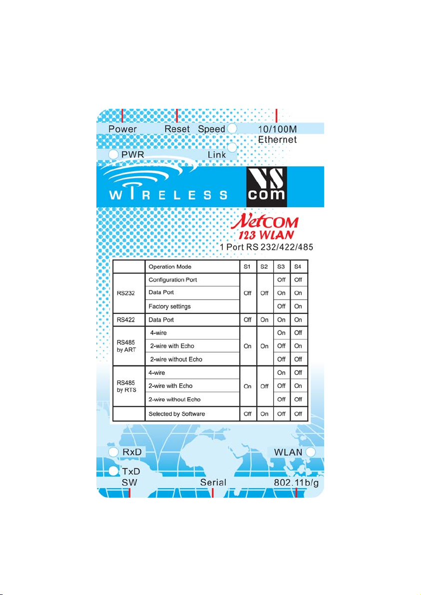
3.3. SERIAL PORT SIMPLE SETTINGS
There is one set of 4 Dip switches to configure the operation mode of
the NetCom Device. This switch is the Master configuration for each
serial port. All ports operate in the same mode, unless the DIP switches
configure for software setting. Before connecting a serial device, the
serial port configuration must be completed.
Warning: a bad configuration may cause serious damage in the
NetCom or the connected device.
To avoid these problems, it is recommended not to connect a device to
the serial ports in the first installation. The serial ports should be
configured for RS232. This is done by setting the DIP switches like this
example.
Image 1: Master Switch
Standard Configuration
Page 15
NetCom 123 WLAN, 423 WLAN,
Page 17

4. WINDOWS DRIVER QUICK INSTALLATION
This section describes the minimum steps required to install the
Windows Driver and Management programs. Most configuration
options are ignored. They are covered in later sections.
Before starting installation, it is essential to have an IP configuration
ready for the NetCom Device to install. You may read the section
TCP/IP Description below. In many networks the default configuration
is fine. If in doubt, please ask your Network Administrator for help.
The following description is based on Windows XP Professional, with
Service Pack 2 installed. The installation on other configurations of
Windows XP is similar.
Further it is assumed the network access is functional. It is
recommended to use Ethernet via Hub or Cross-Over cable.
4.1. INSTALLATION PROCEDURE
The installation of drivers is described first. This is followed by a
procedure to verify a correct installation. The last part of this section is
the uninstall process.
4.1.1. START THE INSTALLATION WIZARD
This is the Installation Wizard, it is named
VSNSETUP.EXE. You’ll find it on the CD-ROM
shipped with the NetCom, in the directory responsible
for your operating system. The drivers are also
Image 2:
Installation Wizard
drivers.
available on the Internet, in the latest version. The
Installation Wizard for Windows NT is named
VSNSTUNT.EXE. Start this program to install the
Your screen displays a VScom logo. Select the folder to install
programs and drivers into. In most situations the suggested setting is
fine, just hit enter.
Image 3: Start Driver Installation
16
823RM WLAN, 1623RM WLAN
Page
Page 18
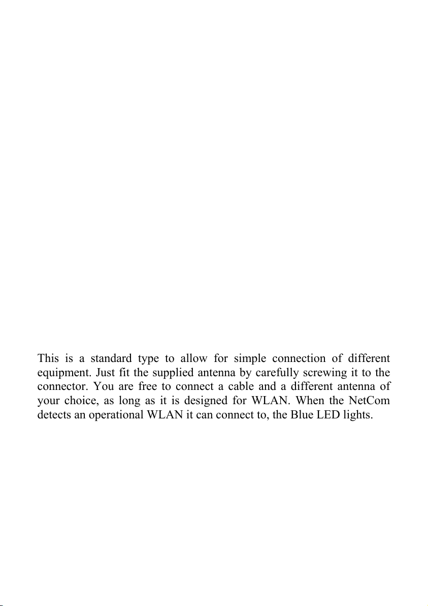
4.1.2. FIND AND CONFIGURE NETCOM DEVICES
Some files are copied to your hard disk, this is the usual process similar
to other Windows installations. When all files are copied, the
NetCom Manager
NetCom Devices on your network.
1
program is started. This searches for all
Image 4: Discover and Select NetCom Devices for Installation
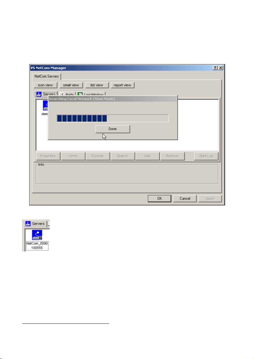
After short time the search process is finished. All
discovered NetCom are listed. In your very first
installation of NetCom Devices and Drivers you should
connect only one NetCom to your network. This single
Image 5: NetCom
in Manager
1
This program is covered in detail in a later section. For now follow the minimum
steps.
Page 17
Device is listed here. Identify it by comparing the serial
number shown in the NetCom Manager.
NetCom 123 WLAN, 423 WLAN,
Page 19
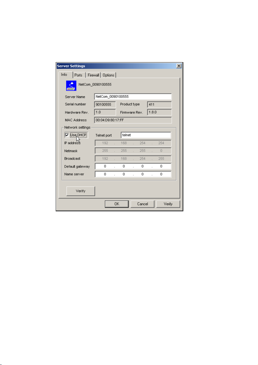
4.1.2.1. Configure IP Parameters
As mentioned above, it is important to configure the NetCom to operate
in your network. In many networks this is done by a special server.
Please ask your Network Administrator for information. If you need to
define parameters manually, double-click the devices icon.
Image 6: Define NetComs IP Configuration
This panel opens. Deselect the Option of “Use DHCP”, and place your
parameters as “IP address”, “Netmask” and “Broadcast”. Click on the
“OK” button.
4.1.2.2. Configure Firewall
As you will see in Image 6 the driver may also operate by traversal of a
Network Firewall. This requires a special configuration, which is
skipped here. Please read in detail in section 5.2.6 Manual
Detection/Installation of a NetCom. For now proceed with the standard
installation.
18
823RM WLAN, 1623RM WLAN
Page
Page 20
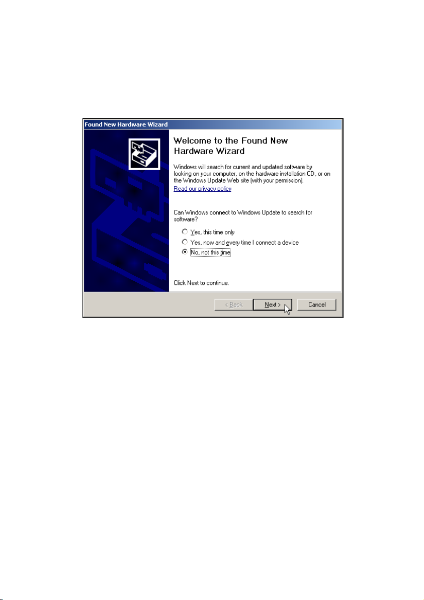
4.1.3. INSTALL DRIVERS
You are now back in the NetCom Manager. Click the “OK” button, the
installation continues. Windows detects the serial ports on the fresh
NetCom as new Hardware. Since Windows XP Service Pack 2 you are
asked about to get latest drivers.
Image 7: Use current drivers dialog
There are no later drivers on the Windows Update website. Select the
third item, and click on “Next”. This question neither appears on
Windows XP prior to SP2, nor on any previous Windows version.
Page 19
NetCom 123 WLAN, 423 WLAN,
Page 21
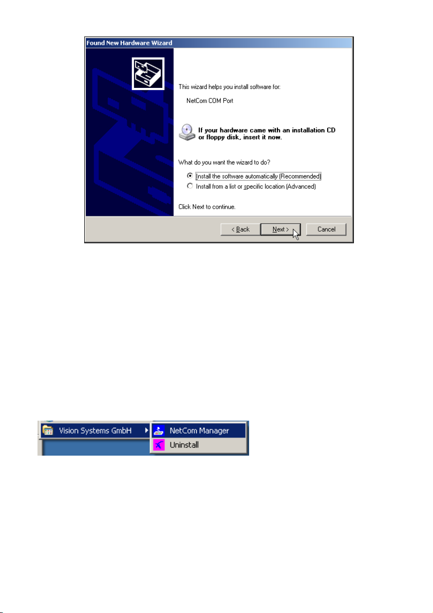
Image 8: Install drivers for the serial ports
The pre-selected automatic installation is fine, just click on “Next”. The
driver files are already copied to your hard disk. Now Windows installs
them in the system directory. To “Finish” the installation click on that
button as it appears.
These latest steps happen for each serial port on the NetCom Device.
Just repeat the procedure, until all ports are successfully installed.
Windows will show you this.
In most situations it is not required to reboot the system. Of course you
can do that now, to test the drivers.
4.2. VERIFY THE INSTALLATION
Image 9: VScom drivers in the Start Menu
In the Start Menu you’ll find “Vision Systems GmbH”, a new program
group. The installed programs are the NetCom Manager and an option
for uninstallation. This group is not installed on Windows NT.
20
823RM WLAN, 1623RM WLAN
Page
Page 22
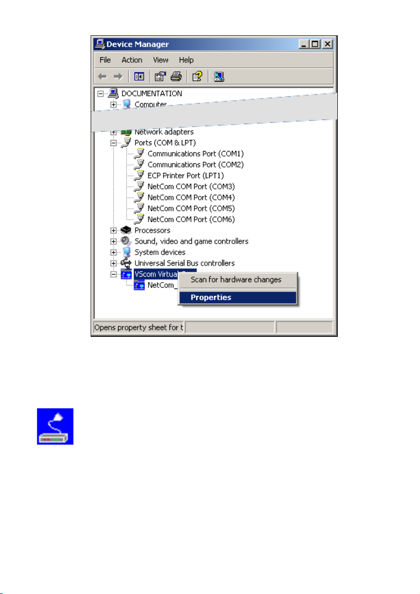
Image 10: NetCom in Device Manager
In the Device Manager the serial ports are listed in the usual section
“Ports”. Additionally there is a new device class
“VScom Virtual Com”. All installed NetCom Devices are listed herein.
The available options are described later.
On Windows NT there is no Device Manager. You’ll
find the serial ports listed in the Control panel in the
Image 11:
NetCom Manager NT
“Ports” applet. To configure the NetCom and special
port options, there is a new applet named NetCom
Manager.
Page 21
NetCom 123 WLAN, 423 WLAN,
Page 23

4.3. UNINSTALL THE DRIVERS
To completely uninstall the NetCom Drivers and files, there are three
methods. The usual way is to use the Add/Remove Programs applet in
the Control Panel, and remove the NetCom Drivers. This will start the
NetCom uninstallation program.
Image 12: Uninstall NetCom Drivers
As a second way you may start the Uninstall program in the start menu.
The third method is to start the Installation Wizard again. This will
detect the drivers on the system. You have the options to repair the
current installation, or to remove the installed drivers.
823RM WLAN, 1623RM WLAN
Page
22
Page 24

5. SOFTWARE CONFIGURATION
The NetCom Devices may also be used without the installation of a
driver software. Customer applications contact the NetCom directly,
using network functions. These setups require independent
configuration of the NetCom Device and the serial ports. There are
several ways to do this configuration. The NetCom offers a
Webbrowser interface, a Manager program to use in Windows,
configuration via serial port, via Telnet and also via SNMP. This SNMP
option is not covered in this manual, please see separate documentation.
The serial port option is a fallback, if every other way of configuration
fails. The options are here described in the order Web, Manager
program, Telnet and serial port.
Configurations via Webbrowser and via Telnet require
a functional TCP/IP connection to the NetCom Device.
Image 13:
NetCom Manager
is a very minimal description of this program. You find this program on
the CD-ROM shipped with the NetCom Device. In Windows 2000, XP
and 2003 it is named NETCOMMGR.EXE, while in Windows NT the
name is NETCOMMGRNT.EXE. Just double-click to start it direct
from the CD-ROM. If you already installed the drivers, the program is
also in the Start Menu.
And you must also know the IP-Address of the
NetCom, to contact it. The easiest way to retrieve this
information is the NetCom Manager program. So here
Page 23
NetCom 123 WLAN, 423 WLAN,
Page 25
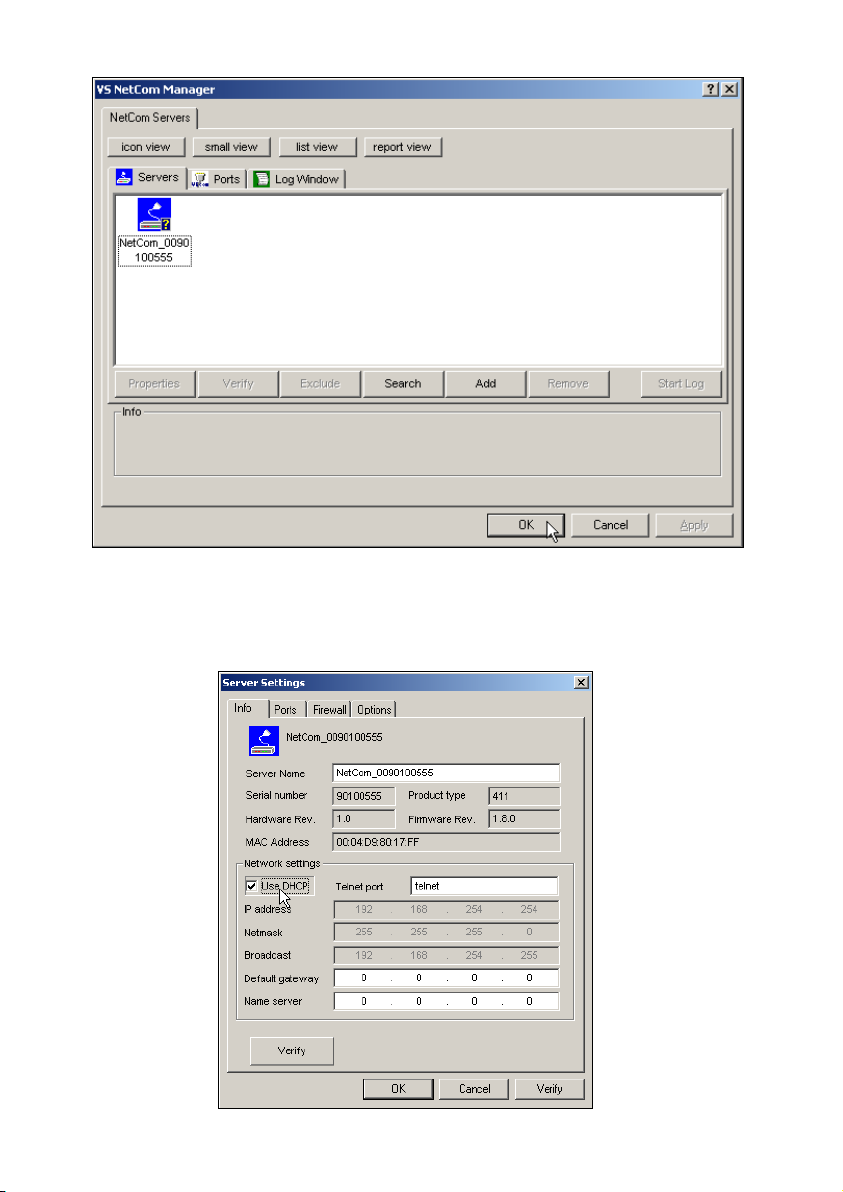
Image 14: NetCom Manager Servers Panel
Identify the NetCom Device by comparing the serial number.
Double-click the Icon of the NetCom. You’ll see the IP-Parameters.
Note the “IP address”, to use it in your browser or via Telnet.
Image 15: NetCom IP-Parameters
823RM WLAN, 1623RM WLAN
24
Page
Page 26
5.1. CONFIGURE IN WEB-INTERFACE
Open your Webbrowser. In the address line type the address of the
NetCom Server. In the example from above type http://192.168.254.254
as the target. You may do this on any operating system you prefer.
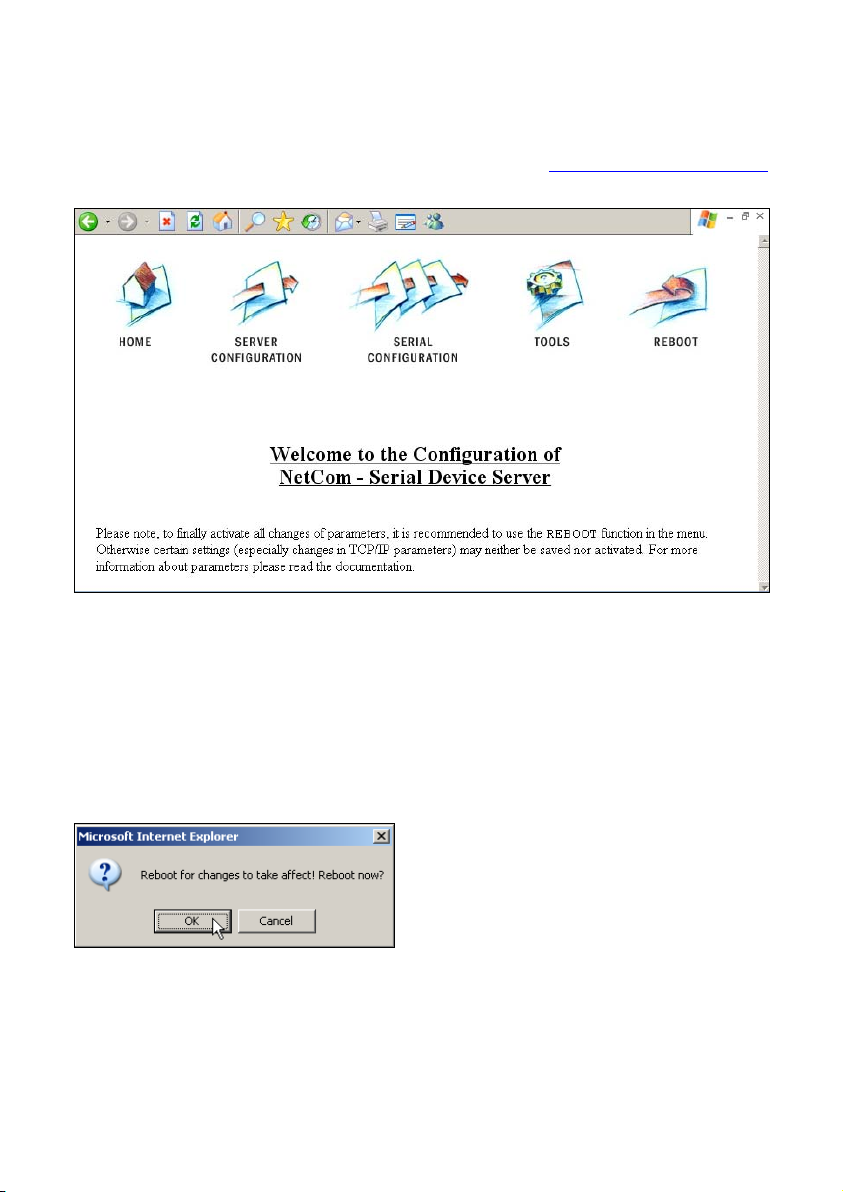
Image 16: Webinterface for configuration
The NetCom welcomes you with its “Home” screen. To access the
different options of configuration, the images above function as a link.
In many menus you’ll see a blue question mark. This is a symbol for
help. When clicked a short explanation pops up, informing about the
function of this parameter. Some other settings require a reboot to save
and activate them. Whenever this situation occurs, the NetCom requests
a REBOOT.
It is done like this here, you may
reboot now, or do that later when
the configuration is finished.
Image 17: Webinterface Request to Reboot
Page 25
NetCom 123 WLAN, 423 WLAN,
Page 27
5.1.1. WEBBROWSER SERVER CONFIGURATION
The Server Configuration is a very long menu. It is divided in its logical
sections throughout this document. There is basic server information,
the server parameters related to the IP-configuration, the parameters for
Wireless communication, the section for encrypted communication,
Password settings, and finally the configuration for date and time.
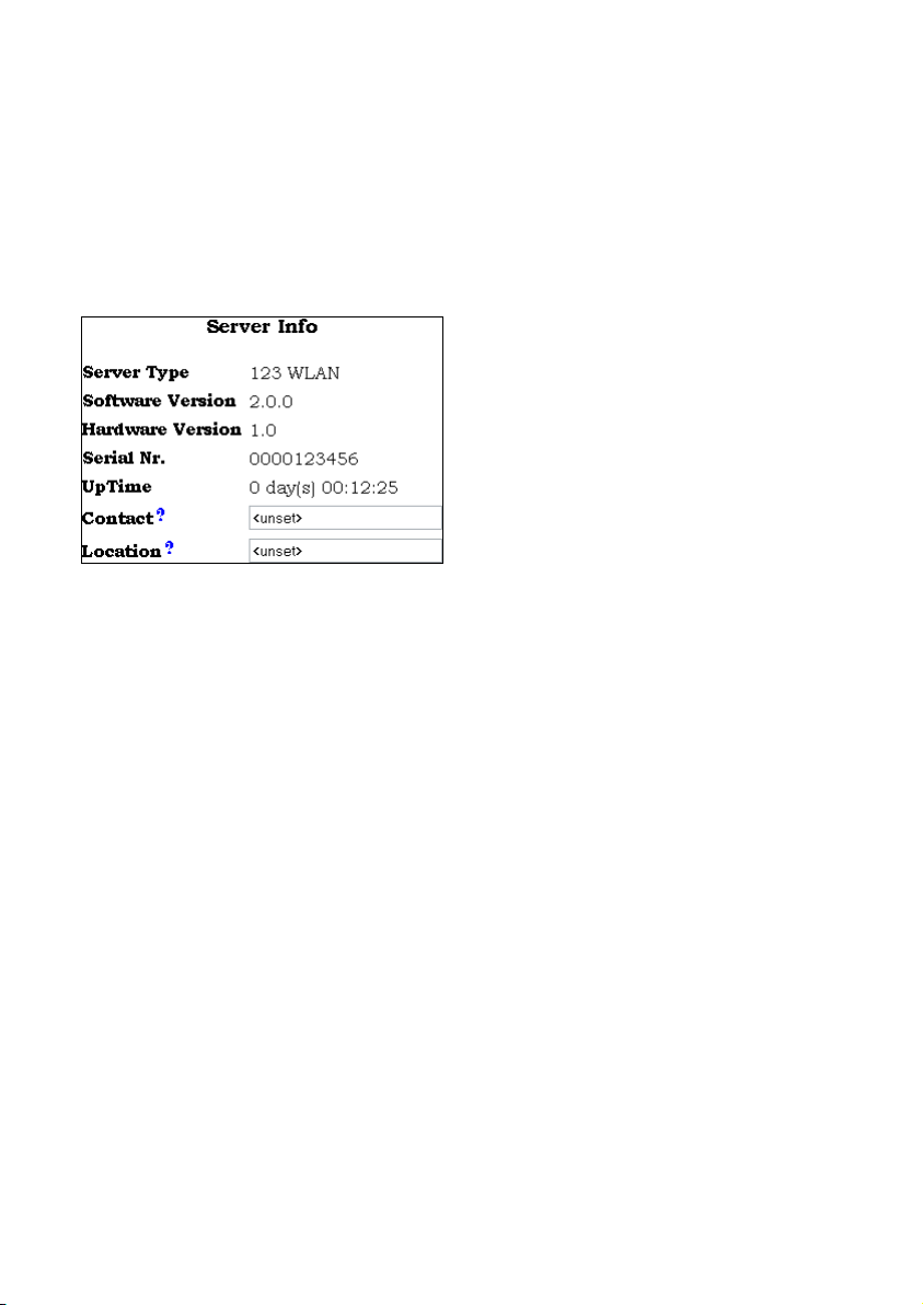
5.1.1.1. Server Info
Information about the selected
NetCom is displayed as
“Server Info”. Starting with the
“Server Type”, this is the model of
the NetCom, followed by the
version of Software and Hardware.
This will give a rough overview,
which features are implemented,
Image 18: Web Panel Server Information
important to identify the device you are configuring right now. For
further information the “UpTime” is listed. “Contact” and “Location”
are User-defined information. They may later help to find the device in
the installation, and the person responsible for management.
or need an upgrade of the
firmware. The “Serial Nr.” is
823RM WLAN, 1623RM WLAN
Page
26
Page 28
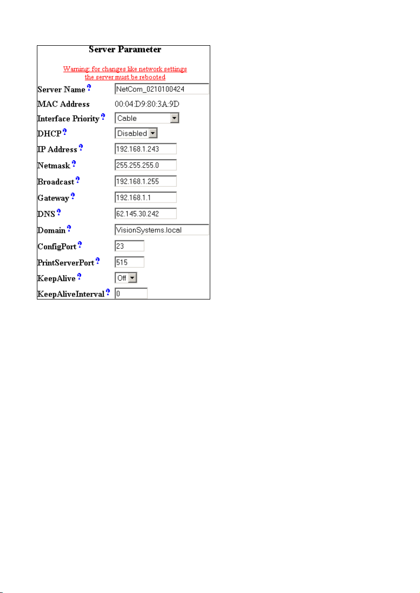
5.1.1.2. Server Parameter
The “Server Parameter” allow
configuration of the NetComs
name and of course all
parameters in IP-settings. The
Server Name is used as the
ESSID of the Wireless Ad-hoc
mode. Generally it is used as
information, e.g. in the
NetCom Manager program or in
SNMP. You may choose the
network interface as
Wireless
or both (with
Cable,
priority).
Manual changes of IP parameters
are only available with “DHCP”
set as
Disabled. When DHCP
is not used, enter “IP Address”
and “Netmask”, as well as the
Image 19: Web Panel Server Parameter
“Broadcast” address. “Gateway”
is required, if there are Routers
in the network. DNS is used to access other stations by name. The
“ConfigPort” is used to access the NetCom for administration via
Telnet. It is suggested to use the standard value for Telnet, TCP port
number 23. However it may be changed for different purposes. This
does not change the function of the Telnet menus.
Firmware version 2.2 introduces the new function as Print Server. The
TCP Port defined by RFC1194 is 515, under certain circumstances you
may change the “PrintServerPort”. More about Print Server function at
the configuration of the serial ports.
“KeepAlive” is an intrinsic function of the TCP/IP protocol. If used it
causes network traffic, but problems are detected earlier. In a LAN this
is usually not a problem. However, if used via DialUp connections this
may cause problems. If this functions is used, you must define an
interval in seconds. NetCom has a better chance to react on network
problems, or failed hosts. Even dropping an old connection may be
useful in certain environments.
Page 27
NetCom 123 WLAN, 423 WLAN,
Page 29

5.1.1.3. Wireless Parameter
To operate a Wireless device, a lot of parameters are required. The
configuration in the NetCom is reduced to a small set of them, for ease
of configuration.
“SSID” is the «Service
Set Identifier». This is
used to get access to
radio cells established by
an Access Point. By
default it is built from the
serial number, as
identification in Ad-hoc
mode.
The “OperationMode” is
Image 20: Web Panel Wireless Parameter
selectable as
a direct connection from
Ad-hoc for
wireless stations to other
stations, and also as
infra to select the «Infrastructure Mode». This
mode is required to connect to an Access Point. Other wireless stations
such as a PC or Laptop use the Access Point to transfer the data to the
NetCom.
The “WirelessMode” is available as
11b and 11b+g. It may be
necessary to use the restriction of 11b when compatibility problems
with other clients occur.
WLAN as of IEEE 802.11b/g define eleven possible channels (i.e.
predefined frequencies) to use with WLAN devices.
The available “CountryRegion” values are
FCC(1-11) for North America.
In Infrastructure Mode the NetCom adapts to the configuration of
the Access Point.
The “Channel” is used in Ad-hoc mode.
“Encryption Type” defines the encryption of the radio transmission. It
may be
Off, WEP or WPA-PSK/TKIP. The WEP encryption may use 40
823RM WLAN, 1623RM WLAN
Page
28
Page 30

or 104 bit keys, sometimes also named WEP40/WEP64 or
WEP104/WEP128. Which of this is required is defined by the
“Encryption Key” Parameter. The key may be entered as ASCII
characters, or as hexadecimal for a binary key. A string with 5
characters is WEP40 using an ASCII key. Using 10 characters as key
defines this key as also WEP40, but with a binary key in hexadecimal
notation. Likewise a 13 character string is WEP104 with ASCII, and 26
characters select WEP104 with a binary key.
WPA Encryption is available for the TKIP protocol. The key is PSK
(Pre-Shared Key) and must be installed on all stations. It is
recommended to use WPA-PSK/TKIP with a binary key, generated
from random data.
“RTSThreshold” and “Fragmentation Threshold” are low level WLAN
parameters. They should match the configuration in the Access Point.
Higher values result in better data throughput. But when transmission
error occur, the impact is dramatic. In this case lower values provide
better security and better performance.
5.1.1.4. Encrypted Communication
Firmware version 2.2 introduces a way for encrypted communication
with the NetCom Serial Device Server. This function establishes an
encrypted VPN tunnel between your computer and the NetCom. All
communication to the NetCom uses this new connection. No
application requires a change of operation, but seamlessly gets the
advantages of Encryption.
To build this tunnel NetCom uses the Open Source product
OpenVPN™ (http://openvpn.net
). This is the configuration of the
parameters on the NetCom side. The function and the configuration of
OpenVPN™ is described with more details later in the section of
OpenVPN™ Client installation.
NetCom 123 WLAN, 423 WLAN Page 29
Page 31

Of course “OpenVPN” may be
Disabled, active as Server or
in the combined Server-
Client mode. When the function
is active, the NetCom is virtually
invisible on the IP-Address
defined in Server Parameter. It will
still answer on ICMP, and also the
Logging function is available.
There is only one connection
accepted by the NetCom, to the
“TCP Port” defined for
OpenVPN™.
There is nothing more available.
The “IP Address” is the local
Image 21: Web Panel OpenVPN Network
Parameter
address on the VPN, it should be a
private address. This VPN also has
a “Netmask” and a “Broadcast” address, this is similar to the
configuration of the “Server Parameter”. The Limit of “Max. Clients”
specifies how many stations may establish simultaneous connections to
the NetCom; it does not limit the number of installed clients. If
OpenVPN is configured for Server-Client mode, it will establish a
connection to a given Server, e.g. another NetCom. The “TCP Port” and
the “IP Address” of the Destination are required.
Different grades of “Encryption” are available, from
no encryption at all to AES with a 256 bit key. Select
the required grade of security, and open the
“Configuration-Settings of the Encryption-Key” to
open a window for the parameters.
Image 22: Web
Panel OpenVPN
Encryption grades
Image 23: Web Panel OpenVPN Key Configuration
This window is for Key management. The NetCom allows to
“Generate” a new key from Random Data. This key is the displayed in
the browser window. Depending on the configuration of your
30
823RM WLAN, 1623RM WLAN
Page
Page 32

Webbrowser, it will attempt to immediately save the key to a file on
your disc. Since the Internet Explorer also shows this behaviour, the
Firmware suggests a file extension of “.cfg” instead of “.key”.
Windows may react crazy on “key”-files. Please also note, this fresh
new key is only displayed/saved. The configuration of the NetCom has
not changed.
To use this new key on the NetCom, you must “Load” it to the NetCom.
This is the way to “Upload” any key to the NetCom, regardless of the
source. Instead of loading a new key to the NetCom, it is possible to
“Show” the key currently used. Again some browsers including Internet
Explorer directly attempt to save the key.
If “Logging” is enabled, NetCom sends the messages of OpenVPN™ to
the standard debug log output.
5.1.1.5. Authentification
”Authentification” sets a password to
restrict access to the configuration of
NetCom. To protect against accidental
Image 24: Web Panel Authentification
mistyping, you must type the Password
twice.
5.1.1.6. Date & Time
It may be helpful to have a correct
time setting in the NetCom. You
may manually enter the time here.
Please note, there is no real time
clock with a battery backup in the
NetCom. When the NetCom is
restarted, the time is lost.
But since Firmware version 1.6 it is
possible to configure NetCom for
automatic time retrieval via SNTP.
Define “State” for retrieval method
of “Interval” or “Startup”, or “Off”
Image 25: Web Panel Date & Time
of course. Parameter “Mode” is
used to find the Time Server. It
may be defined direct, or by DHCP. The “Interval” in seconds instructs
the NetCom to regularly check for an update of the internal time
settings. The Time Server may be given by IP-Address, or by name. A
Page 31
NetCom 123 WLAN, 423 WLAN,
Page 33

name of course requires a DNS server, see at 5.1.1.2 Server Parameter
above.
Below these options there is the button “Save”. This will store all
configurations done here in the NetCom. In many cases NetCom
requires a reboot to proceed.
5.1.2. WEBBROWSER SERIAL PORT CONFIGURATION
This is also a huge menu. Each serial port of the NetCom is listed in a
separate Column. The top half of the parameters titled “Serial Settings”
is directly related to common serial configurations. The bottom half
titled “Transfer Settings” configures the operation mode of NetCom on
the network. Each serial port is configured separately, there is no setting
shared between ports.
5.1.2.1. Serial Settings
The NetCom devices allow to operate in
RS422/485 modes. This is configured by
the Master DIP switches or by software,
“PortType (current)” displays the current
setting. If the DIP switches are set for
«
Selected by Software», the mode
of operation is chosen by the “PortType”
parameter.
Image 27: Web Panel Op-Mode by Software
The serial port is based on enhanced
Image 26: Web Panel Serial Settings
UARTs, the type and maximum speed
are also displayed.
When the NetCom is used via the Virtual Com Driver mode, the serial
parameters are controlled by the application, which opened the serial
port. However certain installations use a different operation without
Driver mode. Then the serial parameters must be defined separately.
This is done in this panel.
32
823RM WLAN, 1623RM WLAN
Page
Page 34

The current UART “Model” may be virtually changed to a less
advanced type. In some situations it may be desirable to deactivate the
FIFO memory, or some other options.
The “Baudrate” may be selected in a drop-down list, or entered
manually. If
Manual is selected in the list, the value in the respective
field is used to transmit data. NetCom checks if the configuration is
possible, and warns otherwise. Note: The “MaxBaudrate” shown is kind
of safe settings. It is achievable in RS232-Mode with proper cabling.
However, the NetCom may operate in RS422 or RS485 configuration.
These are much less sensitive for noise. It is possible to configure a
bitrate of four times the MaxBaudrate, usually 1.843.200 bps.
“DataBit” per character, “Parity” and “StopBit” are quite usual
parameters.
The FlowType is available as standard
configuration. There is also an Advanced
setting, which gives very specific control
to the user.
NetCom can generate Events on RTS,
DTR or as XON/XOFF, when the serial
receive buffer is filled/emptied. It will
also respect the state of CTS, DSR or
XON/XOFF when sending data to the
connected serial device.
Image 28: Web Panel Advanced Flow
Control
The “RxTriggerLevel” defines when NetCom sends the received data to
the host. If the amount of data is this high, the data is sent. It does not
matter if there is still data coming on the serial line. If less data is
received, the NetCom waits some time for further data, before sending
the buffer.
The “TxTriggerLevel” operates similar for the transmission. If the
defined amount is received from the network, the NetCom does not
accept more data to transmit.
Page 33
NetCom 123 WLAN, 423 WLAN,
Page 35

5.1.2.2. Transfer Settings
The Transfer Settings allow different
Image 29: Web Panel Serial Port Mode
Selection
modes. They are selected by the basic
“Mode” setting. Depending on the
current mode, only some of the many
parameters are useful. The web configuration hides those parameters
without function.
Basically the NetCom Devices can act as a server or as a client. As the
main difference a server waits for clients to contact it, while a client
actively contacts a server. A NetCom can do both, and partially both at
the same time. Keep this in mind throughout this section.
5.1.2.2.1. Driver Mode
Only very few parameters have a
function in “Driver Mode”. NetCom is
operating as a Server. It accepts two
connections per serial port. One
connection is used to transmit the
serial data, this is the
Image 30: Web Panel Driver Mode
“TCP Port(Data)”. And the other is
used to transmit control information, “TCP Port(Control)”. This control
connection includes the configuration of the serial port, as well as
signals for changed Modem Status lines. This mode is required when
the serial port is operated via the Virtual Com Driver, it is default.
The NetCom can check if the connected Client is still alive. This may
be done, when a second Client wants to establish a connection
(
On Connect). It may also be done in regular intervals (Polling).
5.1.2.2.2. TCP Raw Server
As TCP Raw Server NetCom operates
very simple. It only waits for incoming
data connections in Raw IP mode. As
with the Driver Mode only the data
connection is defined. As a special
configuration NetCom allows for more
than one connection at a time. If the
number is raised, it is the responsibility
Image 31: Web Panel TCP Raw Server
of the customer to ensure correct
operation. Firmware version 2.2 added
823RM WLAN, 1623RM WLAN
Page
34
Page 36

the option of additional protection by “Password”. When a password is
configured, the NetCom sends the question “Password: “ to the client.
The user (his application) must first send the password, followed by
a <CR> character. The password is not echoed to allow usage with
Telnet on a Monitor.
5.1.2.2.3. TCP Raw Client
Also as Raw Client the NetCom
requires very few parameters.
Under certain conditions it
establishes a Raw TCP connection
to a pre-defined “Destination”.
Since version 2.0 of the NetCom
Image 32: Web Panel Raw Client
Firmware the Destination can hold
multiple hosts as targets for a connection. They are entered as a comma
separated list of DNS names or IP-Addresses. Each destination will
have a TCP port number, separated by a colon. Instead of a single
IP-Address or DNS name, a range of IP-Addresses is also valid. This
range must be followed by the TCP port number, as in 192.168.254.12-
192.168.254.17:2077.
The parameter “Connect” defines if NetCom uses the connections as
Permanent, Triggered or DSR. With Permanent or Triggered
any activity on the serial ports establishes the connection, inactivity of
longer than the “ShortHoldTime” cause NetCom to close the
connection.
DSR is new since Firmware version 2.0, the
TCP-connections follow the state of the DSR signal at the NetCom
serial port. When it becomes active they are established, until DSR
becomes inactive. At that moment the connections are dropped.
Page 35
NetCom 123 WLAN, 423 WLAN,
Page 37

5.1.2.2.4. Null Modem Tunnel
This is a mixed mode, requiring
parameters for server function
and for the destination. The
NetCom operates as a server
while accepting connections in
Driver Mode. If there is no
current connection, the NetCom
may establish a connection as a
client. This is also a special
connection, using the
Driver Mode protocol. NetCom
can will not only transmit serial
Image 33: Web Panel Null Modem Tunnel
data in both directions, it will
also pass information about the
current settings of the Modem Status lines. And it will itself set the
Modem Control lines as required by the other host. Since this operation
requires another NetCom to accept the connection, both NetCom
together operate as a long Null-Modem cable. The data is sent via a
tunnel through the network.
The configuration as Server (top) requires the same parameters as the
Driver Mode, hence “TCP Port(Control)” and “TCP Port(Data)”.
The configuration as Client (bottom) first require a destination. Here it
is given by name, but a direct IP-Address may be more usual. On the
destination there is also a “TCP Port(Control)” and “TCP Port(Data)” to
accept the connect of the NetCom.
The connection is normally established in
Triggered mode, i.e. when
some event occurs on the serial port. It is hold for the defined
“ShortHoldTime”. It is also possible to have the connection
Permanent. As in the normal Driver Mode the function of a connected
client can be checked via KeepAlive signals in different modes.
5.1.2.2.5. IP-Modem
The serial port of a NetCom may
mimic (emulate) a serial modem.
This feature is available since
Firmware version 2.0 of the
NetCom. There is the separate
Image 34: Web Panel IP-Modem
section 8 below defining this
823RM WLAN, 1623RM WLAN
Page
36
Page 38

functionality. Here are the basic network parameters only. A modem
accepts connections from the network, in this case via TCP/IP. The
TCP port for this is defined as the “TCP Port(Data)”. This is the only
parameter required to set here. All other values are normally defined via
AT-commands. However for short, “Destination” allows for up to four
predefined targets, available with special Dial commands. The
“IP Modem Config” is known as the Init String in standard modems.
5.1.2.2.6. TCP Advanced Settings
All of the above operation modes are
special configurations for options. In
some situations none of the
pre-defined modes fit the customers
needs. When this is the case, the
TCP Advanced Settings offer the
configuration of any Transfer
parameter. Unusual combinations of
Modes are possible with this, also
standard modes with unusual
parameters.
Image 35: Web Panel TCP Advanced Settings
5.1.2.2.7. UDP Data Transfer
The UDP mode is available as
a function since the version 1.4
of the firmware. UDP sends
data in single packets instead
of a stream. This protocol
requires a “UDP Port(local)”
for listening to incoming data.
Other stations on the network
Image 36: Web Panel UDP Data Transfer
send their data to this port. The
“Destination” host is
configured by IP-Address or name, plus the target “UDP Port(Dest)”.
“UDP MaxPacketSize” is a limit for the size of UDP packets. When the
amount of data received on the serial port reaches this limit, the UDP
Frame is assembled and sent to the destination.
Page 37
NetCom 123 WLAN, 423 WLAN,
Page 39

“UDP Timeout” defines when NetCom sends the received data as a
UDP Frame. If the reception of serial data is interrupted for this time (in
milliseconds), the data sampled so far is sent to the destination.
“UDP Trigger” defines a sequence of characters. As soon as this
sequence is detected in the received data, all data up to the end of this
Trigger is sent to the destination. In most situations such a Trigger
includes control or other special characters. Enter them numeric: as
\xHH where HH is the hexadecadic code of the character, or as \OOO
where OOO is the octal code of the character. The backslash itself must
be doubled as \\.
5.1.2.2.8. Print Server Function
Firmware Version 2.2 introduces the function as a Print Server
according to RFC1179, also called a »Line printer daemon«. A print
server is accessed through its IP Address via one specified TCP Port
(see Server Parameter). Data is handled in distinct queues, each with a
certain name. Each queue is handled by a certain serial port, and the
data is sent to the serial printer attached to this port.
Each serial port configured for
Print Server operation has its
separate “QueueName”. The
default value is »lpd« plus port
Image 37: Web Panel Print Server Configuration
number. The “InitString” is a
special feature of NetCom. This
string is sent to the serial printer at the beginning of the next queued
print job. The definition is in section 8.2.2.1 below.
5.1.3. WEBBROWSER NETCOM TOOLS
Since Firmware version 1.6.0 the available tools are:
• The Ping utility to check if a station is available.
• Statistic information for each serial port.
• The Netstat utility to monitor used TCP connections.
• The option to detect WLAN devices in the proximity
• The option to update the firmware.
• Saving of Configuration to / Loading from a file.
• Syslog
• DebugLog
823RM WLAN, 1623RM WLAN
Page
38
Page 40

5.1.3.1. Ping
Enter the IP-Address or the name of a station
in the field, and click the “Ping” button. The
network connection is checked by sending
Image 38: Web Panel Ping
certain ICMP data packages.
PING 127.0.0.1 from 192.168.1.87 : 44 (72) bytes of data
52 bytes from 127.0.0.1: icmp_seq=0 ttl=255 time=1.560 msec
52 bytes from 127.0.0.1: icmp_seq=0 ttl=255 time=1.542 msec
52 bytes from 127.0.0.1: icmp_seq=0 ttl=255 time=1.542 msec
back
If the target responds, the network between the NetCom and the target
is operational. The time required for an echo depends on the speed of
the network. In a typical Ethernet this is only very few Milliseconds,
while it can be several seconds throughout the Internet.
5.1.3.2. Statistics
Select the serial port to see its statistical
information.
Image 39: Web Panel Statistics
Port Selection
The statistics window reports the state of the
modem status and control signals. Also the
number of state changes. The number of
characters sent and received is shown at the
bottom.
Image 40: Web Panel Port
Statistics
Page 39
NetCom 123 WLAN, 423 WLAN,
Page 41

5.1.3.3. Netstat
Use Netstat to see the actual connection
status of NetCom. This is a standard tool for
Image 41: Web Panel Start Netstat
network debugging.
Update
Proto Local Address Foreign Address State
tcp 0.0.0.0:23 0.0.0.0:0 LISTEN
tcp 0.0.0.0:80 0.0.0.0:0 LISTEN
tcp 0.0.0.0:2000 0.0.0.0:0 LISTEN
tcp 0.0.0.0:2001 0.0.0.0:0 LISTEN
tcp 0.0.0.0:2010 0.0.0.0:0 LISTEN
tcp 0.0.0.0:2011 0.0.0.0:0 LISTEN
tcp 0.0.0.0:2020 0.0.0.0:0 LISTEN
tcp 0.0.0.0:2021 0.0.0.0:0 LISTEN
tcp 0.0.0.0:2030 0.0.0.0:0 LISTEN
tcp 0.0.0.0:2031 0.0.0.0:0 LISTEN
tcp 192.168.1.243:80 192.168.1.42:1280 TIMEWAIT
tcp 192.168.1.243:80 192.168.1.42:1281 ESTABLISHED
udp 0.0.0.0:161
udp 0.0.0.0:19970
udp 192.168.1.243:32331
Image 42: Web Panel Netstat Output
A “Foreign Address” of 0.0.0.0 is listed when NetCom is waiting for an
incoming connection (
connection is either active (
LISTEN). If the value is not 0.0.0.0, the
ESTABLISHED) or closed (TIMEWAIT).
823RM WLAN, 1623RM WLAN
Page
40
Page 42

5.1.3.4. Wireless
When it comes to Wireless communications, it is useful to see a list of
possible partner stations on the WLAN. This function is available in
many drivers, and also in the NetCom WLAN Serial Device Servers.
This function is often referred to as »Range
Scan«. On the NetCom it will open a
Image 43: Web Panel WLAN Scan
separate browser window with the results.
An example of this is shown below.
Wireless-Devices in Range
Update
Act MAC SSID Channel Mode Enc
X 86:73:F6:22:E1:BA NetCom_0210100462 7 Ad-Hoc
X A6:E8:9E:BE:7D:86 NetCom_0210100444 7 Ad-Hoc
X 00:0F:B5:66:CF:56 NETGEAR 11 Managed X
Current Rate: 11Mb/s
Image 44: Web Panel WLAN Scan Output
This example lists two other NetCom configured for Ad-Hoc
communication on channel 7. Both use no encryption. There is also an
Access Point (listed as Managed), of course in Infrastructure-mode. To
connect to this AP the NetCom must use encryption.
Since the NetCom itself is in Ad-Hoc mode, the communication is
limited to the 802.11b, which results in 11Mb/s as raw transmission
speed.
Page 41
NetCom 123 WLAN, 423 WLAN,
Page 43

5.1.3.5. Firmware
To upload a new version of the firmware, put the name of the file in the
field. Your Webbrowser may allow to
search for the file. Click on the “Update”
button. While loading the file is checked. If
it is valid, it is stored in the Flash Memory.
When the upload is finished, NetCom will
Image 45:
Web Panel Firmware Upload
Reboot.
5.1.3.6. Save and Load
Configuration
Image 46: Web Panel Save/Load Configuration
It is possible to save the actual configuration to a text file. This is first
implemented in Firmware version 1.6. Of course it is also possible to
load the saved configuration into a NetCom.
5.1.3.7. Logging and Debug
Syslogging requires a server the
information is sent to. Facility
allows to select the data sent to
that server.
For Debuglog the NetCom
behaves as the server. Open a TCP
connection to the configured port,
and receive all information
generated.
Image 47: Web Panel Syslog & Debug
823RM WLAN, 1623RM WLAN
Page
42
Page 44

5.2. CONFIGURE WITH MANAGER PROGRAM
Shipped with the NetCom Devices there is a versatile program for
Windows Operating System, named NetCom Manager. This program
shall detect, manage and configure the NetCom Devices in your
network. You can start it by several ways. First of all it is stored on the
CD-ROM, named NETCOMMGR.EXE (NETCOMMGRNT.EXE on
Windows NT). It is possible to start it directly from the CD-ROM.
See this Icon to the left. When the Virtual Com Drivers
are installed, there are more options to run the program.
Image 48:
NetCom Manager
In Windows 2000, XP and 2003 Server the driver software installs a
new device class “VScom Virtual Com”. The properties of the class
open the NetCom Manager. Additionally the installation of the drivers
created a new program group in the Start Menu.
In Windows NT the same Icon appears in the
Control Panel, to start the NetCom Manager program.
Image 49: NetCom Manager in Start Menu
Image 50: NetCom Manager in Device Manager
This section of documentation
focuses on management of the NetCom Devices. The options to
configure driver-specific options of the serial ports are skipped here.
This includes some buttons and panels. They are described in total
below, in the documentation of the drivers and panels.
While in the configuration process, a click on a button or a double-click
on an item opens properties or other options. In many situations, a
right-click with the mouse opens context-sensitive options. Just try it
out. The NetCom Manager is designed to help configure driver options.
So for very detailed configuration of a NetCom, it is better to use the
Webbrowser interface, or do it via Telnet. However, here are the
options.
Page 43
NetCom 123 WLAN, 423 WLAN,
Page 45

5.2.1. STARTING NETCOM MANAGER
When NetCom Manager is started, it will “Search” the NetCom in your
LAN by SNMP. This process may take up to 30 seconds. The devices
in a LAN are typically found in the first seconds. If this is enough for
you, you can stop the search by click on the “Done” button.
Image 51: NetCom Manager “Servers” Panel
The NetCom are listed here in the “Servers” panel. Since the “Search”
uses broadcast mechanisms, the range is limited. If you have routers in
your network, or you contact some NetCom via Internet, you must
“Add” them manually. Enter the network parameters to access the
NetCom.
Select a NetCom, and click on the “Properties” button, double-click the
Icon, or use a right click. Using “Verify” the NetCom Manager contacts
the NetCom to check if it is properly configured and online. “Exclude”
is only useful in conjunction with the Virtual Com Drivers, so skipped
here. “Search” repeats the search from the program start, and may be
used at any time. “Remove” removes a server from this list. This option
is most often used to clear old data from the drivers database. For
monitoring purposes you may select a NetCom, and “Start Log” for
44
823RM WLAN, 1623RM WLAN
Page
Page 46

this. It may be done for several Devices at the same time. The output is
visible in the “Log Windows” panel.
Image 52: NetCom Manager Server Settings
5.2.2. NETCOM SERVER SETTINGS - INFO
As described above, open the “Properties” of a NetCom Device. The
Server Settings start with the “Info” panel. Configure the options as
your network requires.
The “Server Name” is just for information. As factory setting it includes
the serial number of the device. You may change it to any string, since
there is no functionality related to the name. This name is listed in the
Server panel of NetCom Manager. The next parameters are fixed, and
displayed for information only.
The “Telnet port” allows to configure this NetCom via Telnet. The
value is a TCP port. Factory setting is the standard port for Telnet, 23.
By default the NetCom is set to “Use DHCP” for automatic
configuration of IP parameters. This is the suggested method. However
there are several situations where this option can not be used. In this
case deactivate it. When inactive, other parameters may be changed.
Page 45
NetCom 123 WLAN, 423 WLAN,
Page 47

The basic parameters “IP address” and “Netmask” are mandatory. If
any of these is changed, the NetCom Manager calculates a matching
address for “Broadcast”. You may also change this address.
The DHCP option will also configure the “Default gateway” and the
“Name server”. Without DHCP you must enter these parameters by
yourself. However they are not required in all configurations. So enter
0.0.0.0 if they are not used.
5.2.3. NETCOM SERVER SETTINGS - PORTS
Image 53: NetCom Manager Ports Panel
The “Ports” panel lists all serial ports of a NetCom. Some of the options
are driver related, e.g. the “Com Number”. Each serial port may operate
via three TCP ports. The “TCP Control Port” is used in the Virtual Com
Driver mode, and also in Null-Modem Tunnel. If Driver mode is not
desired, this parameter is ignored almost always.
The “TCP Data Port” is used to transmit data to and from the serial
port. Use the default, or change the value to the settings required for
your network. There is also a “UDP Data Port”, used in packet data
transfer. You can not switch the NetCom to UDP mode with the
Manager. But if it is already in this mode, you can change this basic
parameter.
46
823RM WLAN, 1623RM WLAN
Page
Page 48

5.2.4. NETCOM SERVER SETTINGS - FIREWALL
Image 54: NetCom Manager Firewall Panel
Many networks use a Firewall to protect the stations in the network
from other networks, including the Internet. In some situations the
contact to a NetCom must pass through such a Firewall. To do this you
must “Enable Firewall”, and enter the “Address” of the Firewall.
The Manager configures a NetCom via SNMP, which uses UDP. The
Firewall must have a special “Port” to receive those data, and to transfer
it to the internal network. Enter this port here.
The same scheme applies to the logging option. By default a NetCom
listens on port 1200 for logging connections. The Firewall must also
have a special “Log Port” to receive this connection, and to transfer it to
the NetCom.
The NetCom does not need any configuration to operate in a Firewall
protected environment. This configuration here is for installation of the
drivers. There is a Firewall tutorial section later in this manual.
Page 47
NetCom 123 WLAN, 423 WLAN,
Page 49

5.2.5. NETCOM SERVER SETTINGS – OPTIONS
Image 55: NetCom Manager Options Panel
This Panel is available since software version 1.4.8.0, in this enhanced
version. A “Safe to File” of the configuration is available, as well as the
opposing “Load from File” of this data.
You can also “Reboot” the NetCom. This may be useful, e.g. if an old
connection blocks access to the NetCom.
The button “Apply Changes” commits all parameter settings done so far
to the NetCom. And the “Verify” checks the current settings by
reloading the status from the NetCom to the Manager program.
When you want to install a “Firmware Update”, use this button.
The NetCom may be protected for access, in this case you must place
the current “Server Password” in the dialog. The option to change the
password is reserved for a future extension. “Exclude Server” is related
to the Driver installation only.
You may “Enable Log” to see events at the NetCom, for monitoring. If
enabled, the log will also appear in the central “Log Window”. At any
time it’s possible to “Clear” the log, or “Capture” the data to a file.
823RM WLAN, 1623RM WLAN
Page
48
Page 50

5.2.6. MANUAL DETECTION/INSTALLATION OF A NETCOM
Sometimes the NetCom Device Server can not be detected by the
automatic in the NetCom Manager. To detect and configure devices the
protocol SNMP is used. The detection is done by sending out a
broadcast on all available network interfaces of your computer. This
SNMP broadcast is realized as an Ethernet broadcast. Such a broadcast
is only transmitted through Hubs and Switches. When there is a router
between the computer and the NetCom, the broadcast is not transmitted.
This is especially the case when the NetCom is located somewhere via
Internet, but also in big networks of some companies. If this is the case,
the detection has to be done manually. Refer to Image 51 and “Add” the
NetCom by use of the button. Enter the IP-Address of the NetCom in
the NetCom Manager Server Settings, and click the button “Verify”.
Since now the IP-Address of the NetCom is known, the
NetCom Manager sends a request directly to this target. This directed
SNMP request is transported, even by routers. The NetCom sends the
normal reply, giving all required information to the NetCom Manager.
Now it is possible to configure all options as usual. Also the drivers for
virtual serial ports are installable now.
Please note, the drivers require to have the IP Address. They can not
operate using a DNS name, because a driver can not perform a DNS
name resolution. If your NetCom is located on a dynamic IP Address
(e.g. on a DialUp connection with 24 hours disconnection), you need to
reconfigure the driver installation, when the IP Address has changed.
5.2.7. FIREWALL TRAVERSAL CONFIGURATION
There are more difficult situations with a Firewall between the NetCom
and the NetCom Manager. Many Firewalls protect the internal LAN by
using the feature of NAT (Network Address Translation). In this
situation the IP-Address of the internal device is not visible on the
Internet. Only the Firewall can be contacted via its public IP-Address.
The NetCom Manager and the driver software for the virtual serial ports
can handle such setups. But this requires certain configurations.
5.2.7.1. SOHO Firewall example
The most easy situation for such a setup is by using a very simple
SOHO router as the Firewall. This configuration will show the principle
of the technical details. Those principles can be transferred very easy to
the configuration of more complicated installations. On the SOHO
Page 49
NetCom 123 WLAN, 423 WLAN,
Page 51

router there is only one public IP-Address on the external side, and
typically 254 internal IP-Addresses for the LAN side. These internal
addresses may be assigned by DHCP or static. Such routers offer a
feature typically named “DMZ”, which in fact is only a single exposed
host. It is recommended not to use the “DMZ” for several reasons, some
of them are security related.
5.2.7.2. SOHO Virtual Servers
The router also offers “Virtual Servers”, which is the option required
for NetCom installation. These “Virtual Servers” (here named VSrv for
short) operate by a technique called PAT (Port Address Translation).
Certain data addressed to the public IP-Address of the router are
forwarded to the internal private address of the NetCom. The NetCom
can be contacted via the public IP-Address of the router.
First you need to configure the router for some VSrvs. As the absolute
minimum there is one VSrv for the NetCom device itself, and another
two VSrvs for each serial port of the NetCom. Those VSrv are to be
configured for TCP or UDP transmissions. Please read in the manual of
your router how to do that. You need a port for the external interface,
and an IP-Address plus a port for the LAN side. The IP-Address is of
course that of the NetCom. As an example the most easy device is a
NetCom 113. The internal port for SNMP is 161 for UDP. The serial
port requires ports 2000 and 2001 for TCP.
Function External port Internal port
SNMP 8161/UDP 161/UDP
Control 9000/TCP 2000/TCP
Data 9001/TCP 2001/TCP
Configure your router for these example VSrvs, and use the internal
IP-Address of the NetCom for the targets. Connect the NetCom to your
LAN. Now you are ready for a very first test. Use Telnet to connect to
the Data port of the NetCom serial port. Open a console (DOS Box) and
type the command
Telnet <routers-IP-Address> 9001
You will be connected to the serial port. Every character you type is
sent out of the serial port, and every received data is shown on your
screen. The serial parameters are preconfigured in your NetCom.
823RM WLAN, 1623RM WLAN
Page
50
Page 52

5.2.7.3. NetCom Detection through SOHO Firewall
Now open the NetCom Manager as in section 5.2.6 above, and click the
“Add” button. You again get the NetCom Manager Server Settings
dialog. But now you have to select the panel named “Firewall”.
Image 56: NetCom Manager Firewall Panel
Check the Option “Enable Firewall”, and enter the IP-Address of the
router in the “Address” field. In the field “Port” enter the target port for
the SNMP configuration. From the Virtual Server example above this is
port 8161. Since there is no configured VSrv for Logging, ignore this
field. Click the button “Verify” to have the NetCom Manager contact
the router. This is a directed request, so there is no problem with
broadcasts. Some ISP will block the SNMP protocol, which typically
means they do not transport data for 161/udp to their customers (this is
the first reason why port 8161 was used in the example). The router will
transfer the request to UDP-Port 161 on the NetCom, which is the port
for SNMP. The NetCom will answer the request, and send it out to your
computer. The NAT function in the router will exchange the source IP
of the data by its own public value, so the NetCom Manager will see the
Page 51
NetCom 123 WLAN, 423 WLAN,
Page 53

answer come from the router. The NetCom Manager is satisfied with
this data.
This answer brings every required information about the NetCom,
including its internal IP-Address. Select the panel of NetCom Manager
Server Settings to verify the information, but do not make any changes
here.
5.2.7.4. Serial Ports through SOHO Firewall
Now the NetCom is available in the NetCom Manager, but still the
serial ports are not usable. The information of the TCP-ports for the
VSrv related to the serial port is still missing. In the NetCom Manager
Server Settings select the NetCom Manager Ports Panel. In this panel
select one serial port, in this example of NetCom 113 there is only one
serial port. Click the “Properties” button to open the configuration of
the port.
Image 57: NetCom Manager Port Configuration for Driver
Since the Firewall function is enabled, the parameters for “Firewall
mapping” are available for editing. Enter the ports defined in the router,
52
823RM WLAN, 1623RM WLAN
Page
Page 54

9001 and 9000 in this example. Please note, so far there is no number
for the Virtual Com Port available. The driver is not installed in this
moment, and Windows does not know about the available hardware.
This will happen later in the installation. Click the “OK” button, and
proceed with the driver installation as already described.
5.2.7.5. DMZ and Virtual Servers
Why is it recommended not to use the DMZ function of the router?
There are two reasons. The first one is simple, only one device in the
LAN can be defined as the DMZ target. The DMZ is implemented as
“Send all IP data targeted for the router to the DMZ station, as long as
there is no specific rule for a different target”. When a second NetCom
shall be installed on the LAN, the Virtual Servers have to be configured
anyway. The second reason is the security. Using the DMZ the Firewall
in the router becomes transparent. All data from outside is transferred to
the LAN, including all malicious data.
5.2.8. DYNAMIC IP ADDRESS AND OPENVPN™
Since Firmware version 2.2 there is a different method to provide a
tunnel to the NetCom. The option of Encryption uses a Virtual Private
Network (VPN) based on a single TCP connection between the NetCom
and a client computer. Regardless of strong encryption or even weak as
not encrypted, here the key point is the single TCP connection. It is
more simple to provide a Firewall configuration for a single connection,
so the Router Firewall is more easy to set up.
The network link established by OpenVPN™ requires to have a target
address and a port number. Since the basic TCP connection is activated
by the openvpn.exe program, there is the freedom of using a DNS name
for the target device.
With a Dynamic IP Address for the NetCom site, one of the several
Internet services for Dynamic DNS (DDNS) may help. It is even
relatively simple to construct an own version. Using this service the
openvpn.exe program gets the IP Address of the Firewall Router, and
will establish the link. When the IP Address changes (after 24 hours),
the connection first gets lost. OpenVPN™ will continuously attempt to
connect again. When the new IP Address is known via DDNS, the
network link is re-established. The NetCom is available again. Even
when a serial port has been open, the function will continue seamlessly.
Page 53
NetCom 123 WLAN, 423 WLAN,
Page 55

5.3. CONFIGURE NETCOM VIA TELNET CONSOLE
There are many situations, when using the NetCom Manager program
for Windows is not appropriate. And a graphical Webbrowser may also
be unavailable. To enable configuration also in this situation, there is
the Telnet option. It is preferred by many users.
To connect your Telnet session you need the IP-address of NetCom.
Also you must be able to communicate with NetCom via IP. If you can
send a PING to NetCom and receive an Echo, the configuration is fine.
This requires a predefined NetCom, maybe via a DHCP server. You
may also use the NetCom Manager Program (on a different computer)
to find the IP-Address of the NetCom. Start your Telnet program, set it
to use a terminal emulation of VT100. This is recommended, but VT52
is also possible. The Telnet session is closed by the NetCom, when no
user input occurred for at least 3 minutes.
In your Telnet, establish a connection to the NetCom. If the
configuration port is changed from the default 23 for Telnet, use this
port. If the NetCom is password protected, you need to enter the
password right now.
Please enter your password:
Image 58: Telnet Password protected option
When connected to NetCom you must define the type of terminal used.
Please choose your terminal type (1:VT100 2:VT52 [1]): 1
Image 59: Telnet Open configuration menu
54
823RM WLAN, 1623RM WLAN
Page
Page 56

5.3.1. TELNET MAIN MENU
The configuration with Telnet is menu-driven.
+------------------------ NetCom - 123 WLAN V2.0.0 ----------------------------+
| ServerConfig SerialPorts Tools Save&Exit |
+------------------------------------------------------------------------------+
+--------------------------------------------------------------------- h=HELP -+
Server configuration settings
Image 60: Telnet Main menu configuration console
This is the start point for configuration. “ServerConfig” has all options
to configure the NetCom device itself, including the IP-Parameters to
access it. “SerialPorts” defines settings related to the serial port.
“Tools” has some utilities like PING or displays statistics. In “Exit” you
may leave the menu or reboot the NetCom.
At any time you can get a short hint by typing “H” for help.
Page 55
NetCom 123 WLAN, 423 WLAN,
Page 57

5.3.2. SERVER CONFIGURATION MENU
5.3.2.1. Parameter
ServerConfig +--------------------+ | Parameter | | Wireless | | OpenVPN | | Authentification | | Date & Time | | Info | +--------------------+
Image 61: Telnet Server
Configuration
Server Parameter
Server Name [NetCom_0051100021 ]
MAC Address 00:04:D9:80:00:14
Interface Priority Cable, Wireless
DHCP Enabled
IP Address 192.168.1.81
Netmask 255.255.255.0
Broadcast 192.168.1.255
Gateway 192.168.1.1
DNS 192.168.1.3
Domain netcom.vscom.com.tw
ConfigPort [23 ]
PrintServerPort [515 ]
KeepAlive Off
KeepAliveInterval [0 ]
Image 62: Telnet IP-Configuration Parameters
Selecting “Parameter” brings up all Network
configuration items, listed below.
Use the cursors to select the parameter you want to change. Hit <Enter>
to go in edit mode. Type the new value.
“Server Name” identifies the device when the driver software searches
for devices; this will help you find the correct NetCom server.
”Interface Priority” selects the network interface as
Wireless
or both.
Cable,
DHCP is for automatic IP configuration. “IP Address”, “Netmask” and
“Broadcast” are parameters you get from your network administrator.
Same applies to “Gateway”, “DNS” and “Domain”. The “ConfigPort”
is 23 by default, which is standard for Telnet. You should only change
it if you have strong reasons.
”PrintServerPort” is related to the new protocol of RFC1197, mostly
referred to as »Line Printer Daemon«.
”KeepAlive” is the TCP-intrinsic function of connection checking. The
related interval is defined in seconds.
823RM WLAN, 1623RM WLAN
Page
56
Page 58

5.3.2.2. Wireless
ServerConfig +--------------------+ | Parameter | | Wireless | | OpenVPN | | Authentification | | Date & Time | | Info | +--------------------+
Image 63: Telnet Wireless
Configuration
SSID [NetCom_0000123456 ]
OperationMode Ad-hoc
WirelessMode 11 b+g
CountryRegion FCC (1-11)
Channel 7
Encryption Type Off
Encryption Key [empty]
RTSThreshold [2312]
FragmentationThreshold [2312]
Image 64: Telnet Wireless Configuration Parameter
To operate a Wireless device, a lot of
parameters are required. The configuration in
the NetCom is reduced to a small set of them,
for ease of configuration.
“SSID” is the «Service Set Identifier». This is used to get access to
radio cells established by an Access Point. By default it is built from the
serial number, as identification in Ad-hoc mode.
The “OperationMode” is selectable as
between wireless stations, and also as
Ad-hoc for a direct connection
infra. This infra selects the
Infrastructure Mode, which is required to connect to an Access Point.
Other wireless stations such as a PC or Laptop use the Access Point to
transfer the data to the NetCom.
The “WirelessMode” is available as
11b and 11b+g. It may be
necessary to use the restriction of 11b when compatibility problems
with other clients occur.
WLAN as of IEEE 802.11b/g define 11 possible channels (i.e. predefined frequencies) to use with WLAN devices.
The available “CountryRegion” values is
FCC(1-11) for North America.
In Infrastructure Mode the NetCom
823RM WLAN, 1623RM WLAN Page 57
Page 59

adapts to the configuration of the Access Point.
The “Channel” is used in Ad-hoc mode.
“Encryption Type” defines the encryption of the radio transmission. It
may be Off, WEP or WPA-PSK/TKIP. The WEP encryption may use 40
or 104 bit keys, sometimes also named WEP40/WEP64 or
WEP104/WEP128. Which of this is required is defined by the
“Encryption Key” Parameter. The key may be entered as ASCII
characters, or as hexadecimal for a binary key. A string with 5
characters is WEP40 using an ASCII key. Using 10 characters as key
defines this key as also WEP40, but with a binary key in hexadecimal
notation. Likewise a 13 character string is WEP104 with ASCII, and 26
characters select WEP104 with a binary key.
WPA Encryption is available for the TKIP protocol. The key is PSK
(Pre-Shared Key) and must be installed on all stations. It is
recommended to use WPA-PSK/TKIP with a binary key, generated
from random data.
“RTSThreshold” and “Fragmentation Threshold” are low level WLAN
parameters. They should match the configuration in the Access Point.
Higher values result in better data throughput. But when transmission
error occur, the impact is dramatic. In this case lower values provide
better security and better performance.
5.3.2.3. Encrypted Communication
Firmware version 2.2 introduces a way for encrypted communication
with the NetCom Serial Device Server. This function establishes an
encrypted VPN tunnel between your computer and the NetCom. All
communication to the NetCom uses this new connection. No
application requires a change of operation, but seamlessly gets the
advantages of Encryption.
ServerConfig
+--------------------+
| Parameter |
| Wireless |
| OpenVPN |
| Authentification |
| Date & Time |
| Info |
+--------------------+
Image 65: Telnet Wireless
Configuration
To build this tunnel NetCom uses the
Open Source product OpenVPN™
(http://openvpn.net
). This is the configuration
of the parameters on the NetCom side. The
function and the configuration of OpenVPN™
is described with more details later in the
section of OpenVPN™ Client installation.
823RM WLAN, 1623RM WLAN
Page
58
Page 60

OpenVPN Disabled
TCP Port [1194 ]
IP Address [192.168.127.254]
Netmask [255.255.255.0]
Broadcast [192.168.127.255]
Max.Clients [8]
TCP Port (Destination) [1194 ]
IP Address (Destination) [0.0.0.0]
Encryption None
Logging Off
[ Generate Key ]
[ Upload Key ]
[ Stored Key ]
Image 66: Telnet OpenVPN Configuration Parameter
Of course “OpenVPN”
may be Disabled,
active as Server or in
the combined
Server-Client
mode. When the
function is active, the
NetCom is virtually
invisible on the
IP-Address defined in
Server Parameter. It
will still answer on ICMP, and also the Logging function is available.
There is only one connection accepted by the NetCom, to the
“TCP Port” defined for OpenVPN. There is nothing more available.
The “IP Address” is the local address on the VPN, it should be a private
address. This VPN also has a “Netmask” and a “Broadcast” address,
this is similar to the configuration of the “Server Parameter”. The Limit
of “Max. Clients” specifies how many stations may establish
simultaneous connections to the NetCom; it does not limit the number
of installed clients. If OpenVPN™ is configured for Server-Client
mode, it will establish a connection to a given Server, e.g. another
NetCom. The “TCP Port” and the “IP Address” of the Destination are
required.
Different grades of “Encryption” are available,
from no encryption at all to AES with a 256
bit key. Select the required grade of security.
+---------------+
| None |
| AES-128-CBC |
| AES-192-CBC |
| AES-256-CBC |
+---------------+
Image 67: Telnet OpenVPN
Encryption
If “Logging” is enabled, NetCom sends the messages of OpenVPN™ to
the standard debug log output.
Page 59
NetCom 123 WLAN, 423 WLAN,
Page 61

The NetCom allows to “Generate” a new key from Random Data. This
key is displayed in the terminal window. Depending on your terminal
program, you need to have the logging capability active to save the
data, or on other programs you may directly save the screen content.
Here is a sample key displayed.
# Please copy this key into a new text file.
-----BEGIN OpenVPN Static key V1----0f3fc3d7d1d22d5b3ba1e498d27338c7
f8bf452edf484fae209d657b8cabfc58
9d2edb0c84eae68a65d6e93cda961775
1dbf8a7c38a73c9bc5f1a1ce0e0e0729
72b297945d6e0482a84f2397ab5ba8e6
00069892f0e41b8ab4a511d42ca6405c
8348f40652d8045962e8c0bcfc4c2b91
0ee7772be2b54ed0c0574acd9643d3b5
05a260ed54bd3ba730d12863b4f3df5a
4207b90562c6c7a9c27febabf6e0aa69
ebd04188729eed159c48a94a3da4a30e
7411c4ca2fca8afa365c535877dc00a5
306ddab341b0bf5b325be68b849294a5
47b69cc493aaf2329675f63953715952
558190b8964caf707b59801115413059
ea4b955d8f97263c233d280e032ba83e
-----END OpenVPN Static key V1-----
Image 68: Telnet Sample OpenVPN Key
Please note, this fresh new key is displayed. The configuration of the
NetCom has not changed. When you exit this display with the <ESC>
key, you are asked whether you want this key as the new key in your
NetCom.
+------------------------------------------------------------+
| Should the generated key be stored as your new secret key? |
| Yes No |
+------------------------------------------------------------+
Image 69: Telnet use new Key
Select “Yes” to use this new key on the NetCom.
As an alternative you may “Upload” any key to the NetCom, regardless
of the source. Instead of loading a new key to the NetCom, it is also
possible to “Show” the key currently used.
60
823RM WLAN, 1623RM WLAN
Page
Page 62

5.3.2.4. Authentication
ServerConfig
+--------------------+
| Parameter |
| Wireless |
| OpenVPN |
| Authentification |
| Date & Time |
| Info |
+--------------------+
Image 70: Telnet Access
Authentication
Security Settings
Password [empty]
Image 71: Telnet Password Dialog
This menu allows to enter a password. This
password is later required to get access to
NetCom. It is also possible to leave the
password empty.
5.3.2.5. Date & Time
ServerConfig
+--------------------+
| Parameter |
| Wireless |
| OpenVPN |
| Authentification |
| Date & Time |
| Info |
+--------------------+
Image 72: Telnet Date & Time
Since Firmware version 1.6 the NetCom can
retrieve actual date and time from a specified
server.
Retype the value of “Date & Time” for manual setting. The format is
Date and Time Settings
Date & Time [01-01-1970 00:17:33 UTC+0]
Simple Network Time Protocol
State Off
Mode DHCP
Interval [1800 ]
Server [ ]
Image 73: Telnet Date and Time Retrieval options
MM-YYYY HH:M
M:SS UTC+/-TZ
(Time Zone)
The “State” field
has three possible
settings:
- “Off”: disables
DD-
automatic time
retrieval.
- “Startup”: NetCom gets the time at reset or power on.
- “Interval”: NetCom repeats to retrieve time.
The “Mode” field allows to decide how to configure the time server. It
is either possible to get the server by
DHCP, or direct specified. The
Page 61
NetCom 123 WLAN, 423 WLAN,
Page 63

“Interval” defines how often the NetCom retrieves the time from the
“Server”.
5.3.2.6. Info
ServerConfig +--------------------+ | Parameter | | Wireless | | OpenVPN | | Authentification | | Date & Time | | Info | +--------------------+
Image 74: Telnet Information
Info brings up general information about the
device.
Server Info
Server Type 413
Software Version 1.6.0
Hardware Version 1.0
Serial Nr. 0010100454
Contact [<unset> ]
Location [<unset> ]
Image 75: Telnet NetCom Server Information
This dialog displays some basic information about the installed NetCom
server. The Administrator may provide some contact information here.
“Contact” defines a person to contact for help, e.g. “Mrs. Jane Doe,
555-HELP”. “Location” is the physical place of the NetCom, e.g.
“CeBIT Hall 12, Service Box IX.a”.
823RM WLAN, 1623RM WLAN
Page
62
Page 64

5.3.3. SERIAL PORTS MENU
The settings available in this menu are by port. Therefore, first the port
to configure has to be chosen.
SerialPorts
+----------+
| Port 1 |
| Port 2 |
| Port 3 |
| Port 4 |
+----------+
Image 76: Telnet Menu, select serial port
for configuration
Just select the port by placing the
cursor, and then press <Enter>.
5.3.3.1. Communication Parameters
SerialPorts
+---------------------+
| Serial Settings |
| Transfer Settings |
+---------------------+
Image 77: Telnet Configure
Communication Parameters
These settings come in effect in the case of
the Raw connection type; i.e. if the
Driver Mode is not used. The driver will
configure the parameters as the application
requested it.
The parameters are organised in two groups.
The “serial settings” define the basic behaviour of the serial port. And
the “Transfer Settings” configure the operation mode of NetCom on the
network. Each serial port is configured separately, there is no setting
shared between ports.
Serial Settings
Port Nr. 1
PortType (current) rs232
MaxBaudrate 921600
PortType rs232
Model 16950
Baudrate 38400
Manual 110
FlowType None
DataBit 8
Parity None
StopBit 1
RxFifoLength 2048
RxTriggerLevel [1248 ]
TxFifoLength 2048
TxTriggerLevel [800 ]
Image 78: Telnet Serial transfer parameters
The NetCom devices allow to operate
in RS232 and RS422/485 modes. This
is configured by the Master DIP
switches or by software,
+----------------------------+
| rs232 |
| rs422 |
| rs485byART-4-wire |
| rs485byART-2-wire-echo |
| rs485byART-2-wire-noecho |
| rs485byRTS-4-wire |
| rs485byRTS-2-wire-echo |
| rs485byRTS-2-wire-noecho |
+----------------------------+
Image 79: Telnet Op-Mode by Software
“PortType (current)” displays the
current setting. If the DIP switches are set for «
Selected by
Page 63
NetCom 123 WLAN, 423 WLAN,
Page 65

Software», the operation mode is chosen by the “PortType”
parameter.
The serial port is based on enhanced UARTs, the type and maximum
speed are also displayed. These are hardware parameters, and can not
be changed. The current UART “Model” may be virtually changed to a
less advanced type. In some situations it may be desirable to deactivate
the FIFO memory, or some other options.
When the NetCom is used via the Virtual Com Driver mode, the serial
parameters are controlled by the application, which opened the serial
port. However certain installations use a different operation, without
Driver mode. Then the serial parameters must be defined separately.
You may configure the serial transmission by setting “Baudrate” from a
defined list. If you select
Manual in this list, you may enter it numeric
below. If the selected value is not possible, an error is displayed. Also
configure character size, parity mode and the length of the stop bit.
The settings of “RxTriggerLevel” and “TxTriggerlevel” define when
NetCom issues a “buffer empty/full” message. If the values are less
than 16, they have direct impact on the handling of the serial port
hardware FIFO. Also, if you change the UART “Model” to 16450, the
FIFO size is configured to support a single Byte. This option reduces
latency times, by increasing the network traffic.
FlowType +------------+
DataBit | None |
Parity | RTS/CTS |
StopBit | DTR/DSR |
RxFifoLength | XON/XOFF |
RxTriggerLevel | Advanced |
TxFifoLength +------------+
Image 80: Telnet Standard Flow Controls
FlowType Configuration
Port Nr. 1
AutoCTS off
AutoRTS off
AutoDSR off
AutoDTR off
AutoTxXOnXOff off
AutoRxXOnXOff off
Image 81: Telnet Advanced Flow Control
configuration
823RM WLAN, 1623RM WLAN
FlowType opens a submenu of
configurations. Handshaking is
available via Standard
or
RTS/CTS. Also possible is the
use
DTR/DSR. There is also an
Advanced option for detailed and
XON/XOFF
customer specific configuration.
This
Advanced allows to
configure the flow control in a
special menu. Every combination
for incoming and outgoing
flow control may be defined with
this option.
64
Page
Page 66

5.3.3.2. Data Transfer Modes
SerialPorts
+---------------------+
| Serial Settings |
| Transfer Settings |
+---------------------+
Image 82: Telnet Configure Data Transfer Mode
(TCP/IP)
Transfer Settings
Port Nr. 1
Mode Driver Mode
TCP Port(Control) [2000 ]
TCP Port(Data) [2001 ]
KeepAliveMode On Connect
KeepAliveInterval [0 ]
These are TCP/IP parameters. The TCP Port for
“Data” transfers the serial
data, while the TCP Port for
“Control” transfers the
control information defined
by the VS NetCom driver, if
installed. Programs operating
in Raw TCP mode (like
Telnet) connect to the “Data”
port for data transfer.
Since there are more transfer
modes (listed below), all
parameters are explained at
Image 83: Telnet TCP-Ports for Driver and Raw mode
Transfer Settings
Port Nr. 1
Mode +-------------------------+
| Driver Mode |
TCP Port(Control) | Null Modem Tunnel |
TCP Port(Data) | TCP Raw Server |
| TCP Raw Client |
KeepAliveMode | TCP Advanced Settings |
KeepAliveInterval | UDP Mode |
| IP Modem |
+-------------------------+
Image 84: Telnet Available Transfer Modes
the “Advanced Settings”.
To change the current “Mode” of the serial port, place the cursor on the
field and hit enter. A drop-down list of the available modes appears.
Page 65
NetCom 123 WLAN, 423 WLAN,
Page 67

For demonstration purposes the “TCP Advanced Settings” mode is
selected. All parameters may be changed. This allows some unexpected
Transfer Settings
Port Nr. 1
Mode TCP Advanced Settings
Server On
TCP Port(Control) [2000 ]
TCP Port(Data) [2001 ]
Max.Clients [1 ]
Client Off
Destination [ ]
TCP Port(Control) [2000 ]
TCP Port(Data) [2001 ]
Connect Triggered
ShortHoldTime [0 ]
KeepAliveMode On Connect
KeepAliveInterval [0 ]
Image 85: Telnet Parameters for transfer modes
configurations.
Here this is used to
show and explain all
parameters and their
purposes.
Information is also
available On-Screen
when typing h for
help.
NetCom usually acts as a network server. This means it accepts
incoming connections. The most used Driver Mode is explained above.
It is possible to disable this option by setting “Server” to
Off. Usually
there is only one client connection at a time, but the limit can be raised.
NetCom can also operate as a network client, but in most installations it
does not. This is enabled by setting “Client” to On. In certain situations
NetCom contacts a computer (server) defined by “Destination” to send
data. Most customers just need a Raw TCP connection to the server.
The target application is defined by the “TCP Port(Data)”. If the server
is another NetCom, both devices can also exchange control information
via the “TCP Port(Control)”. There are three types of “Connect”,
Permanent, Triggered and DSR. In Permanent mode NetCom
connects to the server immediately. If the connection is interrupted for
some reason NetCom keeps trying until it is established again. In
Triggered mode NetCom connects to the server when data arrives on
the serial port. When no more data arrives, “ShortHoldTime” (in
milliseconds) defines how long to keep the connect before closing it.
Warning: a time shorter than 1000 may cause problems.
DSR is
controlled by the external device via the DSR signal. When the DSR
becomes active at the NetCom, the connection to the target is
established. As long as DSR is active the NetCom operates similar to
823RM WLAN, 1623RM WLAN
Page
66
Page 68

the Permanent configuration. When DSR becomes inactive, the
connection is terminated.
NetCom can monitor an open connection. This is controlled by the
“KeepAliveMode”, which has three settings:
Polling. Please note, this option is effective only in Driver Mode and
Off, On Connect and
Null Modem Tunnel. If the Keep Alive function is required in the other
modes, the global option in Server Parameters is available.
o
Off: no KeepAlives
o
On Connect: when a client is trying to connect to the server and
there was a connection before, the server checks if the first
connection still exists. If it does not exist anymore, the server
accepts the new connection
o
Polling: the server checks in “KeepAliveInterval” (seconds), if a
connection still exists.
There are predefined modes usable as compact configuration options.
Listed and described below.
5.3.3.2.1. Driver Mode
In Driver Mode NetCom operates as a server. It accepts connections on
the Data and the Control port. Both must origin on the same computer,
Mode Driver Mode
TCP Port(Control) [2000 ]
TCP Port(Data) [2001 ]
KeepAliveMode On Connect
KeepAliveInterval [0 ]
Image 86: Telnet Driver Mode parameters
5.3.3.2.2. TCP Raw Server Mode
Mode TCP Raw Server
TCP Port(Data) [2001 ]
Max.Clients [1 ]
Password [******]
Image 87: Telnet TCP Raw Server parameters
this is checked. The parameters
for Keep Alive apply in driver
mode. Only a single client
computer is allowed at a time.
The Control port set to zero is
TCP Raw Server.
The NetCom also operates as
a server in this mode. It only
accepts raw data connections
to the Data port (this is also
possible in Driver Mode). In
Raw Server mode multiple clients may connect. Serial data received is
sent to each client, all clients can send data. The customers application
is responsible to avoid data confusion and damage.
Page 67
NetCom 123 WLAN, 423 WLAN,
Page 69

Firmware version 2.2 added the option of additional protection by
“Password”. When a password is configured, the NetCom sends the
question “Password: “ to the client. The user (his application) must first
send the password, followed by a <CR> character. The password is not
echoed to allow usage with Telnet on a Monitor.
5.3.3.2.3. TCP Raw Client Mode
Mode TCP Raw Client
Destination [ ]
TCP Port(Data) [2001 ]
Connect Triggered
ShortHoldTime [0 ]
Image 88: Telnet TCP Raw Client parameters
In Raw Client Mode
the NetCom is a
network client. Under
defined conditions it
establishes a Raw
TCP connection to a
pre-defined “Destination”. Since version 2.0 of the NetCom Firmware
the Destination can hold multiple hosts as targets for a connection. They
are entered as a comma separated list of DNS names or IP-Addresses.
Each destination will have a TCP port number, separated by a colon.
Instead of a single IP-Address or DNS name, a range of IP-Addresses is
also valid. This range must be followed by the TCP port number, as in
192.168.254.12-192.168.254.17:2077.
The Connect modes and Short Hold Time apply.
5.3.3.2.4. Null Modem Tunnel
Mode Null Modem Tunnel
Server
TCP Port(Control) [2000 ]
TCP Port(Data) [2001 ]
Client
Destination [ ]
TCP Port(Control) [2000 ]
TCP Port(Data) [2001 ]
ShortHoldTime [0 ]
KeepAliveMode On Connect
KeepAliveInterval [0 ]
Image 89: Telnet Null Modem Tunnel parameters
This is a special
mode. Two NetComs
connect via network
and simulate a long
Null Modem cable
between the two
serial ports. This
mode is symmetric,
both NetCom operate
as server and as client
at the same time.
The server part operates in Driver Mode and waits for incoming
connections. Serial data is transmitted, but also control and status
signals on the serial port.
The client part uses the three types of “Connect”,
Triggered and DSR.
Permanent,
823RM WLAN, 1623RM WLAN
Page
68
Page 70

5.3.3.2.5. IP Modem
The serial port of a NetCom may mimic (emulate) a serial modem. This
feature is available since Firmware version 2.0 of the NetCom. There is
the separate section 8 below defining this functionality.
Mode IP Modem
TCP Port(Data) [2001 ]
Destination [ ]
IP Modem Config [ ]
Image 90: Telnet IP Modem Parameters
Here are the basic
network parameters only.
A modem accepts connections from the
network, in this case via
TCP/IP. The TCP port
for this is defined as the “TCP Port(Data)”. This is the only parameter
required to set here. All other values are normally defined via
AT-commands. However for short, “Destination” allows for up to four
predefined targets, available with special Dial commands. The
“IP Modem Config” is known as the Init String in standard modems.
5.3.3.2.6. UDP Mode
UDP is an Internet Protocol, which does not define a connection. There
is no extra data to signal a successful transmission. As a side effect data
may be sent and received faster than with TCP/IP. UDP is available
since Firmware version 1.4.0
Transfer Settings
Port Nr. 1
Mode UDP Mode
UDP Port(Local) [2002 ]
Destination [ ]
UDP Port(Dest) [2002 ]
UDP MaxPacketSize [1458 ]
UDP Timeout [0 ]
UDP Trigger [ ]
Image 91: Telnet UDP Mode parameters
Please compare with the
parameters for TCP Raw
Server and Client Modes.
The parameters to
configure the UDP Mode
are similar to a mixture of
these modes.
Since there is no
connection as in TCP/IP, it
is required to configure the NetCom to receive data via UDP. The only
parameter required is the local port number. To define where to send
the data NetCom needs the Destination, and the port to address there.
Since there is no connection, data can not be sent in a stream. UDP uses
packages. There are several ways to define the content for a package.
The maximum size of such a package may be defined. If this amount of
serial data is received, a package is generated and sent.
“UDP Timeout” (given in Milliseconds) is an interval. If no serial data
is received for this time, all data available so far is sent as a package. A
Page 69
NetCom 123 WLAN, 423 WLAN,
Page 71

value of zero causes all data to be sent immediately.
“UDP Trigger” defines a sequence of characters. As soon as this
sequence is detected in the received data, all data up to the end of this
Trigger is sent to the destination. In most situations such a Trigger
includes control or other special characters. Enter them numeric: as
\xHH where HH is the hexadecadic code of the character, or as \OOO
where OOO is the octal code of the character. The backslash itself must
be doubled as \\.
5.3.3.2.7. Print Server Function
Firmware Version 2.2 introduces the function as a Print Server
according to RFC1179, also called a »Line printer daemon«. A print
server is accessed through its IP Address via one specified TCP Port
(see Parameter in 5.3.2 above). Data is handled in distinct queues, each
with a certain name. Each queue is handled by a certain serial port, and
the data is sent to the serial printer attached to this port.
Transfer Settings
Port Nr. 1
Mode Print Server
QueueName [lpd1 ]
InitString [ ]
Image 92: Telnet Print Server Configuration
Each serial port configured for
Print Server operation has its
separate “QueueName”. The
default value is »lpd« plus port
number. The “InitString” is a
special feature of NetCom. This
string is sent to the serial printer at the beginning of the next queued
print job. The definition is in section 8.2.2.1 below.
5.3.4. TOOLS MENU
5.3.4.1. Ping
Tools +-------------+ | Ping | | Statistic | | Netstat | | Wireless | | Logging | | Firmware | +-------------+
Image 93: Telnet Tools
menu
823RM WLAN, 1623RM WLAN
The Ping tool allows for verification of network
settings. Try to reach some hosts in your local
network.
IP-Address to ping to: [192.168.1.42 ]
Image 94: Telnet Ping test utility
Page
70
Page 72

5.3.4.2. Statistics
Tools
+-------------+
| Ping |
| Statistic |
| Netstat |
| Wireless |
| Logging |
| Firmware |
+-------------+
Image 95: Telnet
Statistics for serial ports
Tools
+----------+
| Port 1 |
| Port 2 |
| Port 3 |
| Port 4 |
+----------+
The Statistics are presented on a by-port base. So
you first select the serial port, and then you have
the information about modem status and control.
Also the amount of data transferred is shown.
Line Status
DTR off (0)
DSR off (0)
RTS off (0)
CTS off (0)
DCD off (0)
RI off (0)
Common
Serial Tx 0
Serial Rx 0
Image 96: Telnet Status and Statistics
5.3.4.3. Netstat
Netstat is a common tool to display the actual status of network
Tools +-------------+ | Ping | | Statistic | | Netstat | | Wireless | | Logging | | Firmware | +-------------+
Image 97: Telnet
Netstat analysis
connections. It may be used to monitor the actual
status of the NetCom.
This is a sample result of Netstat. When there is
more to display, it will start with “1/2” in the first
line. Or even more for a long list. You may change
to a different page by using the Page Up/Down
keys in your Telnet. The display is refreshed in an
interval of some seconds. Use
ESC key to return to
the menu.
1/1
Proto Local Address Foreign Address State
tcp 0.0.0.0:23 0.0.0.0:0 LISTEN
tcp 0.0.0.0:80 0.0.0.0:0 LISTEN
tcp 0.0.0.0:2000 0.0.0.0:0 LISTEN
tcp 0.0.0.0:2001 0.0.0.0:0 LISTEN
tcp 0.0.0.0:2010 0.0.0.0:0 LISTEN
tcp 0.0.0.0:2011 0.0.0.0:0 LISTEN
tcp 0.0.0.0:2020 0.0.0.0:0 LISTEN
tcp 0.0.0.0:2021 0.0.0.0:0 LISTEN
tcp 0.0.0.0:2030 0.0.0.0:0 LISTEN
tcp 0.0.0.0:2031 0.0.0.0:0 LISTEN
tcp 192.168.1.98:23 192.168.1.42:3665 ESTABLISHED
udp 0.0.0.0:161
udp 0.0.0.0:33320
udp 192.168.1.98:10397
Image 98: Telnet Sample Netstat output
Page 71
NetCom 123 WLAN, 423 WLAN,
Page 73

5.3.4.4. Wireless
Tools +-------------+ | Ping | | Statistic | | Netstat | | Wireless | | Logging | | Firmware | +-------------+
Image 99: Telnet Tools
Wireless Option
Act MAC SSID Ch Mode Enc
X 3E:C4:73:F6:48:85 NetCom_0220100838 7 Ad-Hoc
X 86:73:F6:22:E1:BA NetCom_0210100444 7 Ad-Hoc
C2:4C:94:1B:AC:E0 NetCom_0230100152 7 Ad-Hoc
00:0F:B5:66:CF:56 NETGEAR 11 Managed X
Current Rate: 11Mb/s
Image 100: Telnet Sample WLAN Scan Output
When it comes to Wireless communications, it is
useful to see a list of possible partner stations on
the WLAN. This function is available in many
drivers, and also in the NetCom WLAN Serial
Device Servers. This function is often referred to
as »Range Scan«. On the NetCom it will open a
separate browser window with the results. An
example of this is shown below.
This example lists three other NetCom configured for Ad-Hoc
communication on channel 7. All of them use no encryption. There is
also an Access Point (listed as Managed), of course in Infrastructuremode. To connect to this AP the NetCom must use encryption.
Since the NetCom itself is in Ad-Hoc mode, the communication is
limited to the 802.11b, which results in 11Mb/s as raw transmission
speed.
The display is updated automatically when some information changes.
Most noticeably this will be the “Act”-ivity sign.
823RM WLAN, 1623RM WLAN
Page
72
Page 74

5.3.4.5. Logging
Tools
+-------------+
| Ping |
| Statistic |
| Netstat |
| Wireless |
| Logging |
| Firmware |
+-------------+
Image 101: Telnet Syslog
Option
Logging
Syslog Off
Destination [ ]
Facility [1 ]
Debuglog Off
Debug Port [0 ]
Image 102: Telnet Syslog configuration
Since firmware version 1.6 the NetCom has two
options of Logging. There is the standard Syslog,
and a second option of logging via Telnet.
Activate the Syslog, and define the machine with
the Syslog Demon running. Also configure the
Facility parameter.
You may also connect to a special “Debug Port”
5.3.4.6. Firmware
on the NetCom to get all
messages in real-time.
Tools +-------------+ | Ping | | Statistic | | Netstat | | Wireless | | Logging | | Firmware | +-------------+
Image 103: Telnet
Firmware Update
There is an option to upgrade the Firmware of
NetCom. This is either done via the actual channel
(i.e. the serial or Telnet connection). Or
independently via a separate TCP/IP connection.
This setting defines the parameter. The Firmware is
sent coded in base64, via very simple programs like
a second Telnet session, or similar tools.
Firmware Update
Update Port [2400 ]
[ Start Update ]
Image 104: Telnet Settings, Firmware Update via
TCP/IP
Page 73
NetCom 123 WLAN, 423 WLAN,
Page 75

5.3.5. SAVE&EXIT MENU
5.3.5.1. Save Parameter
Save&Exit +------------------+ | Save Parameter | | Exit | | Reboot | +------------------+
Image 105: Telnet Save
current Parameters
5.3.5.2. Exit
Save&Exit +------------------+ | Save Parameter | | Exit | | Reboot | +------------------+
Image 106: Telnet Exit from
configuration
5.3.5.3. Reboot
You also leave the menu here. But the NetCom is restarted. This
Save&Exit +------------------+ | Save Parameter | | Exit | | Reboot | +------------------+
Image 107: Telnet Exit and
Reboot
When some changes are done, it is possible to
save these modified settings here. Confirmation
is requested before doing this.
+---------------------------------+
| Do you want to save the changes |
| Yes No |
+---------------------------------+
You will not be surprised, when you leave the
menu by selecting this option. If you made any
changes of parameters, you must confirm to
save these.
activates any changes in the settings. This
reboot is necessary for some changes like
IP configuration. Others do not require a
reboot. Also here, if parameters are changed
during the session, confirmation for saving
them is requested.
823RM WLAN, 1623RM WLAN
Page
74
Page 76

5.4. CONFIGURE NETCOM VIA SERIAL CONSOLE
In some situations it may be impossible to get network access to the
NetCom Device. If this happens (e.g. by an accidentally
misconfiguration), neither Telnet, nor the webinterface is functional. It
may be even impossible to use the NetCom manager program.
In this case you must you must connect to the NetCom via the serial
port. Disconnect any serial cable from NetCom. Set the DIP-Switches
of port 1 to “RS-232 Configuration”, all switches to Off. Then connect
the NetCom with your computer using a standard modem cable (direct
connection). If you do not have a modem cable, use a Null Modem
cable and plug the Null Modem adaptor to the serial port. On
NetCom 211 or the rack mount versions you need a Null Modem cable
anyway.
Open any serial terminal program (Hyperterminal, minicom, …), select
38400 bps, 8 Bit, No Parity as configuration. Set your terminal to
emulate a VT 100 (recommended, but VT52 is also possible), including
the Arrow keys.
When connected to NetCom you must define the type of terminal used.
This is the same configuration option as described above in 5.3.1 Telnet
Main Menu.
Page 75
NetCom 123 WLAN, 423 WLAN,
Page 77

6. THE VIRTUAL COM DRIVER
If properly configured, the serial ports of the NetCom Devices appear as
virtual serial ports in your computer. The “virtual” means, there is no
real hardware related to the serial port. However the driver offers the
full functionality of a serial port to the system. The interface used by the
driver is VCOMM, which in turn is supported by the Windows API. So
Windows does not see a difference to Com1, and also no application
should detect the change.
This section of the manual covers the correct installation of the drivers
and serial ports. Please do a quick review of the section 4 Windows
Driver Quick Installation, before reading further. As of the time of
writing, the current driver is version 1.4.8.9
6.1. INSTALLATION OF NETCOM SERVERS
Image 108: Select NetCom to install
The NetCom Manager program is started by the Installation Wizard.
Often there are more than only one NetCom listed. And sometimes not
all of them are to be used on this specific computer.
76
823RM WLAN, 1623RM WLAN
Page
Page 78

The “Exclude” button is used for that purpose.
Select a NetCom Device, and click on that button.
The driver will later ignore this NetCom, when
Image 109:
Excluded NetCom
installing and operating the serial ports. The Icon
changes to olive colour.
In “Image 108: Select NetCom to install” above you’ll notice yellow
questions marks at each icon. These appear when the NetCom is not
already installed for the Virtual Com driver. It may also appear, if you
open NetCom Manager without administrative privileges. If the mark
changes to a red exclamation mark, the NetCom is non functional. It
may be without power, the network may be broken, or the device is
completely removed. To clear the display in NetCom Manager just use
the “Remove” button.
If a NetCom has not been operational when the Manager program was
started, it is either displayed with the exclamation mark, or not
displayed at all. You may make it operational be connecting it now. To
install it, use the button “Search” to find it in the network now. Or
“Add” it manually with that button.
Image 110: NetCom Manager Ports View
Similarly you may exclude certain ports on a specific NetCom Server
from installation as a Virtual Com port.
These are the special options used while installing the driver software.
At any time after installation the configuration may be changed by the
NetCom Manager program. This may result in serial ports appearing in
or vanishing from the system.
Page 77
NetCom 123 WLAN, 423 WLAN,
Page 79

6.1.1. CHANGING THE INSTALLATION
There are common situations, when the current configuration needs a
change. In the first case the NetCom has been moved to a different
location, or the logical structure of the network has changed. It may
happen the IP-Address of NetCom is also changed. Either by Automatic
(DHCP), or manually via a different interface like the Webbrowser.
Because of the changed address the driver does not find the serial port
to contact. Now open the NetCom Manager. It will re-detect the
devices. In this process the Manager finds the already installed
NetCom, but with a new configuration. Then the Manager requests
interaction from the
user. This question here
assumes the NetCom
shall be installed from
Image 111: Reconfigured NetCom found
with a new number. If just a reconfiguration occurred, click on “No”.
When you do that, the parameters of the installed Virtual Com are
changed to contact the same serial ports on a new network address.
The second case occurs, when a NetCom is replaced by another device.
This new device shall have the same configuration, especially the same
IP-Address. When you start the NetCom Manager, it will detect a new
device with parameters already in the database. So a similar question
appears. An installation of a new
serial port is assumed again. If the
device shall replace the old one,
Click on the “No” button.
Image 112: Replaced NetCom found
In general the driver software and the NetCom Manager identify the
NetCom Devices by the combination of IP-Address and serial number.
If one of these is changed, the above requests appear.
scratch. This will
produce a Com port
823RM WLAN, 1623RM WLAN
Page
78
Page 80

6.2. CONFIGURE THE SERIAL PORTS
When the serial ports are installed by the Virtual Com driver software,
any application may use them. In the Device Manager they appear as
“NetCom COM Port” (Image 10: NetCom in Device Manager).
Without special tests a program does not see a difference between
Com1 and virtual Com7. For example the HyperTerminal program has
no problem to communicate through these Virtual Com. And this
situation is common amongst most programs.
A typical application selects a serial port, and opens it. After that it
performs the standard configuration of bits per character, parity settings
and number of stop bits. Also the flow control (handshaking) is defined
by the application. Windows sends these requests to the port driver, and
this driver sends the requests to the serial port on the NetCom.
Image 113: NetCom COM Port Serial Settings
The same parameters may be pre-configured in the Device Manager.
This is done via the “Properties” of the “NetCom COM Port”. In the
“Local Settings” tab these standard parameters are defined. Since most
programs configure these parameters by themselves, the values are very
rarely used. A typical situation is a serial printer attached to this virtual
port.
Page 79
NetCom 123 WLAN, 423 WLAN,
Page 81

As usual this behaves different in Windows NT. There is no Device
Manager. To change these standard parameters, open the “Ports” applet
in the Control Panel.
However it is suggested you open the new “NetCom Manager” applet
instead. Change to the “Ports” view as in Image 110: NetCom Manager
Ports View. Double-click on the small icon at the left side. In this
dialog go to the “Local Settings” tab, as seen above.
6.3. PERFORMANCE ISSUES
However operation through the network causes some extra time, which
is approximately 5 Milliseconds. With a port internal to the computer
this time may be just some 100 Microseconds. This has an impact on
reaction times. Some data protocols may be sensible. A lot of
configurations are possible to compensate for this. But these have an
effect on the sheer data throughput of the virtual serial port.
Image 114: NetCom COM Port Performance Settings
Consequently the configuration starts on the “Performance” tab. There
are four already defined sets of parameters. The default configuration is
for “Best Performance”. The driver software and the NetCom
communicate with big data blocks. As a result a reaction on short
events on the serial port is somehow delayed. For applications operating
80
823RM WLAN, 1623RM WLAN
Page
Page 82

with short data blocks, and waiting for short answers this is not optimal.
It causes transmission delays, called Latency.
In three steps the Latency may be reduced, at the cost of reduced
throughput for large data blocks. The fastest setting “Virtual FIFO Off”
simulates a deactivated FIFO. The port is configured as if the FIFO is
off, buffers are configured to never wait for a timeout, hence gaining in
best reaction times. “Short Latency” mimics a 16C550 with full FIFO
enabled, but no network timeouts will occur. Use the ”Driver Default”
to get the standard setting.
Use “Advanced” to get access to detailed configuration.
6.4. NETWORK & MISC PROPERTIES
When you use the “Advanced” checkbox on the “Performance” tab, the
“Network & Misc” tab opens automatically.
Image 115: NetCom COM Port Network & Misc Properties
The parameters on this tab control the operation of the driver software
on the computer.
Page 81
NetCom 123 WLAN, 423 WLAN,
Page 83

“Tx Network Buffer Size”: If the application sends small chunks of data
to the driver, these are buffered to send them in one large packet.
This defines the size of the buffer. And also the maximum packet
size sent to the serial port by the driver software.
“Rx Network Buffer Size”: This is the size of the buffer to receive data
from the NetCom.
“Automatic Trigger”: based on internal rules, this checkbox selects a
best practice value for “Tx Trigger Level”. Deactivate it to control
that parameter manually.
“Tx Trigger Level”: Controls the time when data is sent to the
NetCom. If the Tx buffer holds at least this amount of data, the
driver immediately sends them. If there is less data, the driver
uses a timeout to determine when to send them.
“Network Timeout (ms)”: This is the timeout.
“Overspeed”: This is a special option, not really related to network
communication. There are old applications, limited in the
maximum speed. With Overspeed you define a multiplier. The
baudrate requested by the application is multiplied with this
factor. The result is sent to the NetCom to configure the serial
port. E.g. the application may be limited to 38,400 bps, but there
is a modem capable of 230,400 bps on the serial port. Set
Overspeed to a value of 6.000, and configure the application to
use 38,400 bps.
“Open If Absent”: The NetCom may be used from a computer with a
DialUp connection. When this option is used, the driver will delay
the connection to NetComs serial port. Even when an application
opens the port, and configures the parameters, no data is sent. The
connection is established when data is sent to the NetCom, or
when status information is requested.
“Keep Alive”: This option will periodically send control information to
the NetCom to check, if the connection is still operational. As a
side effect a DialUp connection will not automatically close.
“Passive Modem”: This option controls how often the driver retrieves
Modem status information from the NetCom. If activated, the
driver never asks for the modem status. Instead the NetCom
informs the driver of any changes. If an application frequently
requests the Modem status, it gets the last value received. On slow
networks like the Internet this option is recommended.
823RM WLAN, 1623RM WLAN
Page
82
Page 84

If inactive, the driver software retrieves the Modem status from
the NetCom serial port each time the application requests it. With
a maximum frequency of 10 per second. If the latest retrieved
information is not older than 100 milliseconds, this value is
returned.
“Simulate Device Off on Connection Loss”: When this option is
enabled, the NetCom driver does not attempt to preserve
transmitted data. If on a normal serial port the connected device is
switched off, all data sent to this device gets lost. NetCom
simulates this behaviour. All data sent from the application to the
driver is discarded, when the TCP connection to the NetCom is
lost. The NetCom attempts to re-establish the connection in
regular intervals. When it is available again, data may be
transferred from then on.
6.5. REMOTE SETTINGS PROPERTIES
The other panel created by activating the “Advanced” checkbox on the
“Performance” tab, is the “Remote Settings” tab.
Page 83
Image 116: NetCom COM Port Remote Settings Properties
NetCom 123 WLAN, 423 WLAN,
Page 85

The parameters on this tab control the operation of the serial port on the
NetCom Device. They are defined and activated by the driver software.
“Tx Trigger Level”: The serial port on the NetCom Device buffers data
for transmission to external devices. If the amount of data in this
buffer drops below this level, the NetCom is capable to receive
new data. It will send a related event to the driver software.
“Rx Trigger Level”: When the serial port has received this amount of
data, these are sent to the driver on the connected computer. If the
amount is less than this, the NetCom applies a timeout of about 5
character times. This means the timeout varies with the serial
transmission speed.
“Remote Flow Control” signals the NetCom to perform the handshake
on its own. This is necessary, because the network delay of some
milliseconds is to long for reliable operation in many situations.
To use this option, Firmware version 1.8.0 is required for the
NetCom.
“Enable”: The configuration shown here is active, when the pre-defined
performance levels are used. When using the “Advanced” option,
Remote Flow Control is completely disabled. Enable as required.
While it is best practice to configure as above, you can disable certain
events here. “CTS”, “DSR” and “Tx XON/XOFF” control the
output of data to the serial port. And “RTS”, “DTR” and
“Rx XON/XOFF” are used to stop transmission from the
connected device. An application has the option to use any
combination of these methods at the same time. The command to
use them is transferred to the NetCom. For example, if the port is
configured to use Hardware Flow Control, the NetCom will
control the RTS line, and observe the CTS line. If requested, any
of these methods may be unchecked. In that case the driver
software on the computer will control the lines.
“Override App Settings”: In rare situations it is necessary to ignore the
applications configuration. Check this box, and select the
Flow Control to use with the device.
“Limits”: These buttons are prepared for future software versions.
823RM WLAN, 1623RM WLAN
Page
84
Page 86

7. UNINSTALLING THE SOFTWARE
The drivers and services install as usual. So it is easy to remove the
drivers from the system. The entry is found in Control panel, section
“Add/Remove Programs”. It is removed like other applications.
Image 117: Uninstall in Control Panel -> Add/Remove programs
You must confirm the uninstall operation and the devices are removed
from the system. Further all driver and configuration files are removed
from the Windows- and System-directories. A simple de-installation via
the Device Manager may result in some driver files scattered in
Windows.
There is also a separate uninstall item in the Start Menu. This is the
same procedure as in the Control Panel. You are also asked to confirm
the de-installation of the drivers.
Image 118: Uninstall in the Start Menu
Image 119: Confirm Uninstall of Drivers
Page 85
NetCom 123 WLAN, 423 WLAN,
Page 87

You may also start the Installation Wizard a second time. It will detect
the installed drivers. The options are to Re-install the drivers, this is
similar to a repair
installation. And it is
possible to completely
uninstall the current
drivers.
Image 120: Installation Wizard to uninstall Drivers
823RM WLAN, 1623RM WLAN
Page
86
Page 88

8. SPECIAL FUNCTIONALITIES
This chapter documents some functions and protocols, not directly
related to the basic function of a serial port. There is the Modem
Emulation by IP-Modem, the Print Server mode, and the encrypted
communication by OpenVPN™.
The technical details of these operation modes are described in this
separate section, because it would be to confusing to have the details in
the description of the configuration menus.
8.1. IP MODEM FUNCTION
The Firmware version 2.0 brings the new function of IP Modem. Used
in this mode, the serial port of the NetCom emulates a standard serial
modem. Basically this means the NetCom will
a) answer to AT-commands on the serial port
b) establish a connection to a destination
c) inform the connected serial device of the connection
d) accept a TCP connection, and inform the serial device of that
event
For connections the NetCom will use a TCP connection. This differs
from a normal telephone line, so there will be some modifications in the
behaviour. The target is an IP-Address, not a phone number. Also for
hardware reasons the automatic baudrate detection used in today serial
Modems is not available. However this is not a problem at all, the
IP Modem can be installed in Windows as a Standard 33600bps
Modem. Later there will be an INF-file for ease of installation.
8.1.1. SOME POSSIBLE SCENARIOS:
1. The customer has a remote management installation, operating
via telephone line. These lines may be in-house or through
public phone systems to other destinations. The customer wants
to reduce costs for these lines, management and possibly
hardware, using the Intra- or Internet.
2. The customer wants to contact several stations from a central
server. Because of frequent target changes he does not want to
define the target by a Virtual Com Port.
3. Remotely distributed devices contact a central system by
Modem. This is the reverse of option 1.
Page 87
NetCom 123 WLAN, 423 WLAN,
Page 89

4. A computer without Network access shall have at least limited
control on the connections established by a NetCom.
5. Old fashioned BBS installations become accessible via Internet.
The typical multi-modem box is replaced by a NetCom Server
with multiple ports configured for IP Modem operation.
8.1.2. SERIAL SIGNALS AND CABLES
A real modem provides the same signals as the serial port of a PC.
However, where a signal is an output on the PC, it is an input to the
modem, and vice versa. So in the NetCom the emulation of a modem
must be incomplete. By exchanging RxD and TxD the data connection
is fine, the same for handshaking RTS and CTS. The DTR of the PC is
connected to DSR of NetCom, this is simple. The RI may be ignored,
some connectors for serial ports also do that.
However a real modem provides DSR and DCD to the PC. There is
only the DTR left on NetCom to serve these signals. In most
configurations the NetCom-DTR serves as the DCD to the computer.
The cable must provide a DSR to the PC then, e.g. by shortcut to the
PC-DTR. In some configurations the NetCom-DTR must serve as the
DSR. This is configurable by a command.
The recommended cable connects as shown in this table. Please note,
this installation does not use the simply crossed signals. Especially the
DSR of the PC is internally connected to the DTR of the PC.
DB9m PC IP-Modem DB9m DB9f
3 TxD ----- RxD 2 3
2 RxD ----- TxD 3 2
7 RTS ----- CTS 8 7
8 CTS ----- RTS 7 8
6 DSR PC-DTR (internal loop-back)
4 DTR ----- DSR 6 4
1 DCD ----- DTR 4 6
5 GND ----- GND 5 5
The limitation of signals is a restriction in function, compared to real
world serial modems.
Page
823RM WLAN, 1623RM WLAN
88
Page 90

8.1.3. OPERATION MODES BY IP MODEM
The function of IP-Modem may be configured port by port. On a
NetCom with a single port there is no much of a difference. However a
NetCom with two or more serial ports operates each port independently.
In the following sections of this manual the phrase “serial port of a
NetCom, configured to operate as IP Modem” is replaced by
“IP Modem” for brevity.
Two basic operation modes are available. The first and default mode is
Modem-to-Modem. This requires a serial port of a NetCom configured
as IP Modem on both ends of the connection. When one IP Modem
dials the other, the connection is established on the TCP level. Directly
afterwards both IP Modems negotiate to ensure, they are a real NetCom
IP Modem and are free for connection. If successful both issue a
“CONNECT …” response to the serial connected devices. This is
convenient for the customer to understand. The CONNECT may report
some parameters, e.g. the minimum serial speed used by both Modems.
These extra parameters are not implemented so far.
The other mode is named as Modem-to-Host. The destination is any
software, which opens a TCP port for Listen. It may be a second
NetCom configured for TCP Raw Server Mode. It may also be the
customers application, running on a certain computer. This mode offers
less features.
8.1.4. HAYES COMMANDS
The IP Modem operates with a command set similar to those in real
Modems. All of the commands start with the character sequence ΑΤ.
8.1.4.1. AT command set
The following table lists many standard commands (in alphabetical
order). The AT is omitted for brevity. The discussion of the functions is
below the tables in section 8.1.5 below.
Page 89
NetCom 123 WLAN, 423 WLAN,
Page 91

8.1.4.1.1. Standard AT-Commands
These commands are based on the old Hayes Modem
AT Hayes-Standard IP Modem Function
A Answer Call Accept a connection
Bn ITU-T modulation Define some modem operation modes
Dnnn Dial connection,
basically phone
number as nnn
Connect to the target system by
IP-Address and TCP-Port. E.g.
ATD10,0,8,42,2023 will “dial” to
port 2023 on IP-Address 10.0.8.42
E Echo on/off Enable/Disable local echo of
command
H0 Hang up Terminate the TCP connection.
I Device Information I0 through I9 report information
L Speaker Volume Ignored, always answered with OK
M Speaker On/Off Ignored, always answered with OK
N Auto serial speed N0 no Auto, N1 reports error
O Return to data mode
Q Result Codes Enable or disable result codes/strings
S=nn/S? S-Register Set/request configuration registers
V0/1 Responses Numeric/text responses to commands
X Busy/Dial detect Ignored, always answered with OK
Z Reset to User profile Standard
Table 7: IP Modem Standard AT-Commands
8.1.4.1.2. Extended AT-Commands
AT Standard-Extensions IP Modem Function
&C DCD control When to turn on DCD (by
IP-Modems DTR)
&D DTR meaning Hang Up, Command Mode or Reset
&F Load factory Default
&K Flow Control
&S DSR control When to turn on DSR (by IP-Modems
DTR)
&V View Profiles
&W Store Profile &W0/&W1 is “Standard”. ATZ1
loads profile 1
823RM WLAN, 1623RM WLAN
Page
90
Page 92

&Zn=dd Save for short dial Define possible targets by DNS name
or IP-Address
%C1 V.42bis enable Ignored
\Q Flow control See &K
Table 8: IP Modem Extended AT-Commands
8.1.4.1.3. Non-AT commands
All these commands apply in Command Mode. If a Dial command
succeeds with a CONNECT, the IP-Modem is in data mode. Every data
received on the serial port is sent to the other station/IP Modem. And
there is a special character sequence in Data Mode, which changes back
to Command Mode. This sequence is +++ by default, with an interval
of 1 second before and after this command; the three characters must
appear in one second.
8.1.4.2. S-Registers for Configuration
Traditional there is a set of registers to control certain operations. These
registers are controlled via the AT S-command mentioned above. This
is a list of those supported by IP-Modem.
Reg. Function Range/units Default
S0 Auto-Answer Ring 0-255 0 (no Auto-Answer)
S1 Ring Counter 0-255 0 (read only)
S2 Escape Code 0-127 (ASCII) 43 (= “+” for
“+++”)
S3 Carriage Return 0-127 13
S4 Line feed 0-127 10
S5 Backspace 0-32, 127 8
S8 Comma pause 0-255 (seconds) Accept but ignore
S9 Carrier detect response
1-255 (0.1 sec) 6
time
S12 Escape Guard time 20-255 (0.02
50 (= 1 second)
sec)
S25 DTR Ready Delay 0-255 (0.01 sec) 5 (= 50 msecs)
S26 RTS to CTS Delay 0-255 (0.01 sec) 1 (= 10 msecs)
S30 Disconnect Timer 0-90 (seconds) 0 (read only,
AT\Tnn)
Table 9: IP Modem S-Registers for Configuration
S0 is frequently used to configure a modem to auto answer incoming
calls. S1 may be checked by software if S0 is Zero, i.e. no
Page 91
NetCom 123 WLAN, 423 WLAN,
Page 93

Auto-Answer. S2 may be set to a different character, if the “+++” may
happen in typical data. Otherwise the software must insert a pause in
the transmission.
8.1.4.3. Sample Commands used by Windows
The NetCom IP Modem is intended for manual installation as kind of a
“Standard Modem” in Windows. The reference is the MDMGEN.INF
file. The commands used in that file are:
"AT&F", "ATA", "ATH",
"AT &F E0 V1 &C1 &D2 S95=47 S0=0<cr>", "ATS0=0<cr>",
"ATX4", "ATS7=<#>", "AT%C", "AT\N", "AT&K", "ATS30=<#>",
"ATB", "ATDP", "ATDT", "ATL", "ATM"
8.1.5. DESCRIPTION OF AT-COMMANDS
The commands are listed more or less in a functional grouping.
Configuration commands are listed also with their default settings in
brackets.
8.1.5.1. AT D (dial)
This is the general Dial command. The target is defined as IP-Address
plus TCP-port number. The dots in the address are replaced by a
comma, and the TCP port is also separated by a comma. On normal
modems a comma generates a pause in the dialling sequence. This is
commonly required, so all software will support it; even multiple
comma.
The modifiers “T” for Touch Tone and “P” for Pulse dialling have no
direct equivalent on the TCP connection. They are used to change
between Modem and Host mode, if the ATB command enables this
(ATB2 or ATB3). Otherwise the IP Modem will ignore them.
Basically dialling is done to a given IP-Address plus a TCP port
number. The IP-Address is given in decimal Octet format, where
comma replaces the dot as the separator. This is followed by another
comma, separating the TCP Port from the IP-Address. If the port is
omitted, the target port is the same as the local TCP Data Port as
defined in the configuration of IP Modem (see 5.1.2.2.5 or 5.3.3.2.5
above).
There are situations where the target is known by a DNS name. This
name can not be used in a dial string, mostly because very few software
will support it. So there is the option of dialling to a pre-defined entry
by shortcut. This is given by an “S” followed by one or two digits. The
shortcuts S90 to S99 are reserved; so far only S1 to S4 are
823RM WLAN, 1623RM WLAN
Page
92
Page 94

implemented. Shortcuts are defined and saved by
AT&Znn=<FDN:Port>.
All other non-numeric characters are understood as modifiers. The
IP-Modem will simply ignore them. This especially applies to space
characters. Typically dial strings are:
ATDT192,168,254,254,2003<cr>
Dial another IP Modem
as a Modem-to-Modem
AT&Z12=demokit.vscom.com.tw:23<cr>
Define a shortcut for
configuration port
ATDPS12<cr>
Dial the other IP Modem
as Modem-to-Host
8.1.5.2. AT O (online / data mode)
If a connection is established, the IP Modem can still be in command
mode. The ATO activates the transparent data mode.
8.1.5.3. AT A (answer call)
Have the IP Modem answer an incoming call, and establish a TCP
connection. This command is required if Auto-Answer is disabled.
Observe the operation mode defined by ATB.
8.1.5.4. AT B (modulation) [ATB1]
This command is used to define the modulation to use on the phone
line. Since the only “modulation” available is IP, there is no choice. The
command is used to change between Modem-to-Modem and
Modem-to-Host mode.
ATB0
ATB1
ATB2
Modem-to-Host mode
Modem-to-Modem mode, which is the default
Modem-to-Modem when Touch Tone dialling, Modem-to-Host
when Pulse dialling. Answer in Modem-to-Modem.
ATB3
Modem-to-Modem when Touch Tone dialling, Modem-to-Host
when Pulse dialling. Answer in Modem-to-Host.
8.1.5.5. AT E (echo) [ATE1]
Disable and enable the echo of the commands received. ATE0 to
disable and
ATE1 to enable the echo.
8.1.5.6. AT Q (quiet) [ATQ0]
Configures the Modem to remain quiet. The Modem will not send any
response messages to the serial port.
Page 93
NetCom 123 WLAN, 423 WLAN,
Page 95

8.1.5.7. AT V (verbose) [ATV1]
Responses as numeric values (ATV0) or as text strings (ATV1).
OK 0 CONNECT 1
RING 2 NO CARRIER 3
ERROR 4 CONNECT 1200 5
NO DIALTONE 6 BUSY 7
NO ANSWER 8
8.1.5.8. AT H (hangup) [ATH0]
Command to disconnect. Also used as ATH0. The related version
ATH1 to just go off-hook is not supported, and reports an ERROR.
8.1.5.9. AT I(n) (information) [ATI0]
Report technical information about the IP-Modem. It is frequently used
to identify the device. The answer is always sent as
<cr><lf><#response#><cr><lf> <cr><lf>OK<cr><lf>. Here are the
defined #response#-strings.
ATI or
230 230.4kbps maximum
ATI0
ATI1
ATI2
ATI3
100000000 100Mbps Ethernet
Version 1.0 / <compile-date> Version of
Modem-Firmware
ATI4
ATI5
ATI6
ATI7
ATI8
ATI9
ATI10
ATI11
Current Profile
NetCom 230k IP-Modem Device Identification
(<Name>\Serial#\IP-#:port\ComX\NetCom)
Display serial port
used
<very extended information>
8.1.5.10. AT S (setup)
Set and read the S-registers for configuration. ATSrr? is a request to
read the current value, ATSrr=nnn stores the value nnn in the register
rr. Unknown registers report ERROR. See Section 8.1.4.2 above for
possible registers and parameters.
823RM WLAN, 1623RM WLAN
Page
94
Page 96

8.1.5.11. AT L (loudness)
8.1.5.12. AT M (speaker)
These commands are answered with OK, but completely ignored. There
is no function like speaker.
8.1.5.13. AT N (auto baud) ATN0
Automatic detection of serial speed. For hardware reasons this detection
is not implemented. The command ATN0 is accepted and answered
with OK. The ATN1 for automatic detection is not available, and
answered with the ERROR response.
8.1.5.14. AT Z (reset)
Reset the configuration to a stored profile. IP Modem only supports
profile 0 for simplicity. Same as ATZ0 or as AT&F or AT&F0.
8.1.5.15. AT &F (factory settings) [AT&F0]
This command has been designed as “Reset to Factory settings”, while
ATZ simply meant reset. At time of invention users could change the
default behaviour of their Modem, which was activated by ATZ.
Nowadays the ATZ is ignored by many software. Instead AT&F is
used, followed by complex initialisation strings. User may save profiles,
which are selected by AT&F0 or AT&F1. There is no longer a
documented way to revert to Factory Defaults.
While IP Modem itself has such a way, this is not usable to simply reset
the configuration as Modem. So IP Modem will support only user
profile 0, and it uses AT&F9 to really reset the user profile to the
Factory defaults.
8.1.5.16. AT &C (DCD configuration) [AT&C1]
Configure the DCD signal to the PC. As IP Modem this signal may be
generated by the DTR output. A standard modem can have DCD always
on, and it can have the DCD follow the external carrier signal. When set
to always on by AT&C0 the DCD may have a separate source. The
DTR is free to serve as a DSR to the PC. The operation of DSR is
defined by AT&S, so these commands are related. An
AT&C1
is the
default, the DTR operates as DCD to the PC (this will require a cable
connecting NetCom DTR to the DCD of the PC).
This command has priority over AT&S.
8.1.5.17. AT &S (DSR configuration) [AT&S0]
Configure the DSR signal to the PC. As IP Modem this signal may be
generated by the DTR output. A standard modem can have DSR always
on, as long as the Modem has power. Or it can have the DSR signalling
Page 95
NetCom 123 WLAN, 423 WLAN,
Page 97

whether the IP Modem is in command or in data mode. When set to
always on by AT&S0 (this is the default) the DSR may have a separate
source. The DTR is free to serve as a DCD to the PC. The operation of
DCD is defined by AT&C, so these commands are related. An AT&S1
has DSR follow the data mode.
The AT&C has priority over this command. AT&S1 can only be
effective, if AT&C0 is set.
8.1.5.18. AT &D (DTR configuration) [AT&D2]
Understand the DTR signal of the PC. The input on the IP Modem is
the DSR, which requires a proper serial cable. Usually this signal is
either ignored, or serves to disconnect from the phone line. There are
four options:
AT&D0 Ignore DTR from PC
AT&D1
AT&D2 Toggle DTR to disconnect and enter command
Toggle DTR to enter command mode
default
mode
AT&D3 Toggle DTR to reset the IP Modem perform
ATZ
8.1.5.19. AT &K (handshake) [AT&K3]
AT \Q [AT\Q3]
Configure serial Flow Control. AT&K0 and AT\Q0 disable all
Flow Control. The default is AT&K3 and AT\Q3 to use RTS/CTS
Hardware Flow Control between PC and IP Modem. AT&K4 and
AT\Q1 configure for XON/XOFF Software Flow Control between PC
and IP Modem. Other Options are not supported.
8.1.5.20. AT &V (view profile)
Show Profiles. This will display the current profile, the stored user
profile, the short dial strings and the factory profile. Parameters are
accepted but ignored. AT&V is AT&V0 and is AT&V1.
8.1.5.21. AT &W (save profile) Save the current configuration as user profile. AT&W is the same as AT&W0, all other commands report an ERROR.
8.1.5.22. AT &Z (save destination)
This command will save a destination in internet syntax. It is given by
<host>:<port>. The <host> is either an IP-Address in dotted octet
notation, or an FQN in correct syntax. The <port> is a string
representing a decimal number. If :<port> is omitted, the target port is
823RM WLAN, 1623RM WLAN
Page
96
Page 98

the local TCP Data Port as defined in the configuration of NetCom (see
5.1.2.2.5 and 5.3.3.2.5 above).
8.2. PRINT SERVER OPERATION
Sometimes the NetCom Serial Device Servers are used together with
serial printers. These printers are available via a network to several
stations for printing. So far there have been two operation modes to
achieve this. First the serial port can operate as a TCP Raw Server, and
the station just sends the data to print via a TCP connection. As second
option a computer running Windows could install the driver for virtual
serial ports. The printer is then controlled via this Com port. In both
these solutions the buffering of data occurred on the client station.
Beginning with Firmware Version 2.2 the NetCom Devices offer a true
Print Server mode, using the Line Printer Daemon protocol as of
RFC1197. Here a print server (lpd) is a station with one IP Address and
a single defined port to accept commands and data for printing. Several
printers may be attached to the print server. Each printer has a separate
data queue for management of print jobs. The data of the jobs is saved
in this queue, instead of the client as before.
8.2.1. PRINTER QUEUE
The basic function of an lpd is to accept the data for printing, store it in
a spooler queue, and send it to the printer when this is ready for
printing. This is done for several queues in parallel. Each printer is
identified by the name of the queue, where it is attached to. The
NetCom Device Servers allow to configure a custom name for each
queue, while the default name is »lpd« plus the number of the serial
port (lpd1, lpd2, …). This name is set in the properties of the serial port.
When the lpd is running on a separate computer, the hard disk is used to
save the data of the queues. The NetCom Servers neither have a mass
storage device, nor huge amounts of memory. Each queue accepts at
least one job with a size of up to 250 KB print data. If the job has more
data, memory is either assigned dynamically to save the job, or the data
is spooled through a ring buffer. Data is printed while the client still
sends data. The amount of available dynamic memory depends on the
number of ports in a NetCom Device Server, and the operations active
on these ports.
Page 97
NetCom 123 WLAN, 423 WLAN,
Page 99

8.2.2. PRINTER RESET
Before a new job is sent to the printer, this printer should be in a well
known state. On a parallel printer port this is easy to achieve. There is a
defined signal to send a »reset« command to the printer.
Such a definition is not available for serial printers. Instead there is a
reset command, which users may send via the serial line. Typically this
command is specific to the manufacturer or even to the printer model.
So the NetCom allows to specify this command by entering an
“InitString” for each queue.
8.2.2.1. Init String Definition
The Initialisation of the printer typically involves ASCII control codes,
ordinary ASCII characters and some binary data. On some models it
may also be necessary to provide a certain state of the modem control
signals RTS and DTR, applied with special timing. The “InitString” in
the NetCom Device Serves offer all these options.
8.2.2.1.1. ASCII Text
Ordinary ASCII characters are entered as they are on the keyboard. The
single exception is the ‘Less Than’ character ‘<’, which is used for
other special functions.
8.2.2.1.2. ASCII Control Codes
ASCII control codes are entered by their standard name, enclosed in
‘Angle Brackets’, i.e. in ‘<’ and ‘>’ (Greater Than). Some examples of
this are <ESC>, <CR> or <TAB>.
8.2.2.1.3. Numeric Codes
Especially binary data must be send by means of its numeric value.
Since the ‘<’ ASCII character has a special function, the only way to
use this is the numeric method. This also applies to printable characters
of some Extended ASCII character sets.
The NetCom accept the decimal value, also enclosed in angle brackets.
Up to three decimal digits define the character to send to the printer.
The ‘<’ is used as <60>, while the <ESC> may also sent as <027>. The
‘>’ may be used directly, however for clarity <62> should be preferred.
8.2.2.1.4. Modem Control Signals
Via the “InitString” control of RTS and DTR is available. This manual
does not make statements about voltage levels on the signals, these are
just set to an active or inactive state. <RTS+> and <RTS-> activate and
deactivate the RTS signal, while <DTR+> and <DTR-> do the same for
DTR.
823RM WLAN, 1623RM WLAN
Page
98
Page 100

8.2.2.1.5. Timing Options
Especially when using Modem Control signals it will be required to
hold them in a given state for a defined amount of time. This may be
done by applying a »Pause«-command in the “InitString”. The delay is
given as numeric value in milliseconds (msec), preceded by a ‘P’. So
<P50> causes the NetCom to wait 50 msec before proceeding with the
next command or start printing. Up to three digits are possible. If more
than 999 msec are required, the Pause-command must be repeated.
Please note: The delay is not executed as an exact time. NetCom
guarantees to wait at least the required amount of time. The smallest
delay possible is 10 msec, due to internal handling of date and time.
8.2.2.2. Reset Example
For example here is a hypothetic serial printer. The serial port operates
at 1200 bps, 7 bit and even parity and 1 stop bit. For Reset the printer
requires the command “<ESC>@0” sent with DTR and RTS off. When
the data is transmitted, DTR must be on, and 50 msec later RTS must
also be on.
Each character sent is 10 bits long, including the start bit. At 1200 bps
each character needs 8.3 msec for transmission. So the transmission
lasts for 25 msec. To be sure the control signals are active, an extra
delay is applied after change of signals. The resulting string would be
<RTS-><DTR-><P10><ESC>@0<P35><RTS+><P50><DTR+>
The delay of 35 msec after the command data shall ensure, all data is
completely transmitted to the printer.
8.2.3. OPERATION IN WINDOWS®
The Printer Server mode may be used to support serial printers in
Windows® Operating System. This is a short instruction how to install
and use it. Experience on installing printers in Windows is required for
this instruction. First the installation of a new printer is given, the
modification of an existing printer setup is described later.
8.2.3.1. Add a New Printer
From »Control Panel« open the »Printers and
Faxes« windows. Select the »Add a printer«
option. The usual »Add Printer« Wizard appears.
Click the “Next” button to select the port, where
the printer is attached to.
Page 99
NetCom 123 WLAN, 423 WLAN,
Image 121: Add a printer
 Loading...