

VSC NX2240w-E Service Manual
22″LCD TV VSC NX2240w-E
1
Service
Service
Service
TABLE OF CONTENTS
Description Page Description Page
SAFETY NOTICE
ANY PERSON ATTEMPTING TO SERVICE THIS CHASSIS MUST FAMILIARIZE HIMSELF WITH THE
CHASSIS AND BE AWARE OF THE NECESSARY SAFETY PRECAUTIONS TO BE USED WHEN SERVICING
ELECTRONIC EQUIPMENT CONTAINING HIGH VOLTAGES.
CAUTION: USE A SEPARATE ISOLATION TRANSFOMER FOR THIS UNIT WHEN SERVICING
8.PCB Layout…………………….……….…….....76
8.1 Main Board…………….……………....….......76
8.2 Power Board…………………….....….......78
8.3 IR Board...…................................................79
8.4 Tuner Board……..………................................80
8.5 Key Board……………................…….........80
9. Block Diagram........................….......................81
10. Schematic Diagram.…....………………….......82
10.1 Main Board……………….........................82
10.2 Power Board...……………………………...94
10.3 IR Board…………..………………………96
10.4 Tuner Board...….........................................97
10.5 Key Board…….…….................................101
11. Exploded View…….....................................102
12. PPL………………………….……………..….103
13. BOM List….………………………………….104
Table Of Contents.......……..............................…........1
Revision List.…........................................……......2
Precautions and Safety Notices…………............……......3
1.General Specifications..............................………........6
2.Operating Instructions…………………….……….......7
2.1.RCU Code……………….…..…………..................7
2.2 Front Panel Control Knobs.....................…...........10
2.3 OSD Operating…………….…............……...............11
2.4 How To Connect...………........................…............14
3.Input/Output Specification............……………............18
3.1 Input Signal Connector............………….................18
3.2 Factory Preset Display Modes..................................19
4. Circuit Description…………………………...………….20
5. Adjusting Procedure…………………………..………..51
6.Mechanical Instructions.....……......................66
7.Repair Flow Chart.……………………..................71

22″LCD TV VSC NX2240w-E
2
Revision List
Version Release Date Revision History TPV Model
A00 Sep-28-2007 Initial Release E227ANNBBWVWNN

22″LCD TV VSC NX2240w-E
3
Precautions and Safety Notices
1. Appropriate Operation
(1) Turn off the product before cleaning.
(2) Use only a dry soft cloth when cleaning the panel surface.
(3) Use a soft cloth soaked with mild detergent to clean the display housing.
(4) Disconnect the power plug from AC outlet if the product is not used for a long period of time.
(5) If smoke, abnormal noise, or strange odor is present, immediately switch the Multimedia TV off.
(6) Do not touch the panel surface with sharp or hard objects.
(7) Do not place heavy objects on the Multimedia TV, video cable, or power cord.
(8) Do not use abrasive cleaners, waxes or solvents for your cleaning.
(9) Do not operate the product under the following conditions:
- Extremely hot, cold or humid environment.
- Areas susceptible to excessive dust and dirt.
- Near any appliance generating a strong magnetic field.
- Place in direct sunlight.
2. Caution
No modification of any circuit should be attempted. Service work should only be performed after you are
thoroughly familiar with all of the following safety checks and servicing guidelines.
3. Safety Check
Care should be taken while servicing this Multimedia TV display. Because of the high voltage used in the inverter
circuit, the voltage is exposed in such areas as the associated transformer circuits.
4. Power Supply Requirements
The external AC power operating range shall be from 90 to 264Vac.
5. Multimedia TV Handling Precautions
5.1. Handling Precautions
(1) Since front polarizer is easily damaged, pay attention not to scratch it.
(2) Be sure to turn off power supply when inserting or disconnecting from input connector.
(3) Wipe off water drop immediately. Long contact with water may cause discoloration or spots.
(4) When the panel surface is soiled, wipe it with absorbent cotton or other soft cloth.
(5) Since the panel is made of glass, it may break or crack if dropped or bumped on hard surface.
(6) Since CMOS LSI is used in this module, take care of static electricity and insure human earth when handling.
(7) Do not open nor modify the Module Assembly.
(8) Do not press the reflector sheet at the back of the module to any directions.
(9) In case if a Module has to be put back into the packing container slot after once it was taken out from the
container, do not press the center of the CCFL Reflector edge. Instead, press at the far ends of the CFL
Reflector edge softly. Otherwise the TFT Module may be damaged.
(10) At the insertion or removal of the Signal Interface Connector, be sure not to rotate nor tilt the Interface
Connector of the Multimedia TV.
(11) After installation of the Multimedia TV into an enclosure, do not twist nor bend the Multimedia TV even
momentary. At designing the enclosure, it should be taken into consideration that no bending/twisting forces are
applied to the Multimedia TV from outside. Otherwise the Multimedia TV may be damaged.
(12) Cold cathode fluorescent lamp in Multimedia TV contains a small amount of mercury. Please follow local
ordinances or regulations for disposal.
(13) Small amount of materials having no flammability grade is used in the Multimedia TV.
The Multimedia TV should be supplied by power complied with requirements of limited Power Source, or be
applied exemption.
(14) The Multimedia TV is designed so that the CFL in it is supplied by Limited Current Circuit. Do not connect the
CFL in Hazardous Voltage Circuit.
22″LCD TV VSC NX2240w-E
4
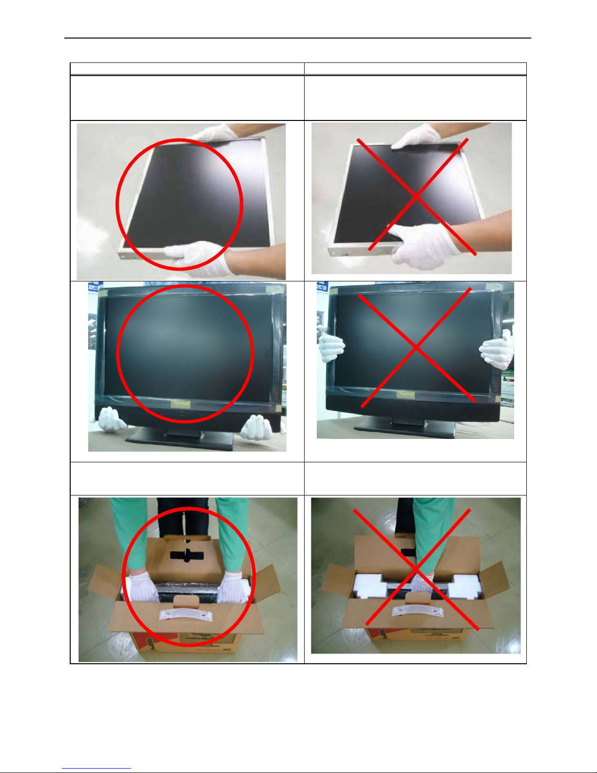
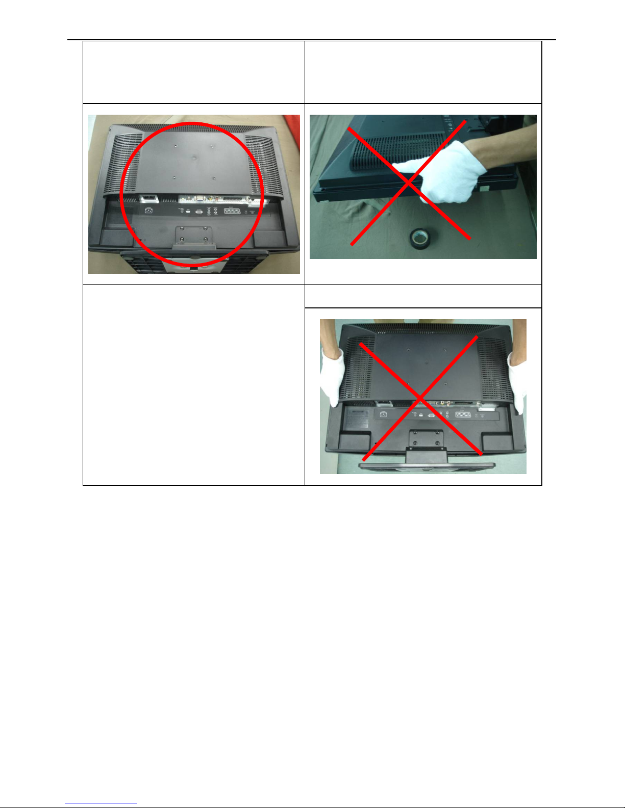
5.2. Handling and Placing Methods
Correct Methods: Incorrect Methods:
Only touch the metal frame of the LCD panel or the
front cover of the monitor. Do not touch the surface of
the polarizer.
Surface of the LCD panel is pressed by fingers and
that may cause “Mura”
Take out the monitor with cushions Taking out the monitor by grasping the LCD panel.
That may cause “Mura”
22″LCD TV VSC NX2240w-E
5
Place the monitor on a clean and soft foam pad. Placing the monitor on foreign objects. That could
scratch the surface of the panel or cause “Mura”
The panel is placed facedown on the lap. That may
cause “Mura”
22″LCD TV VSC NX2240w-E
6
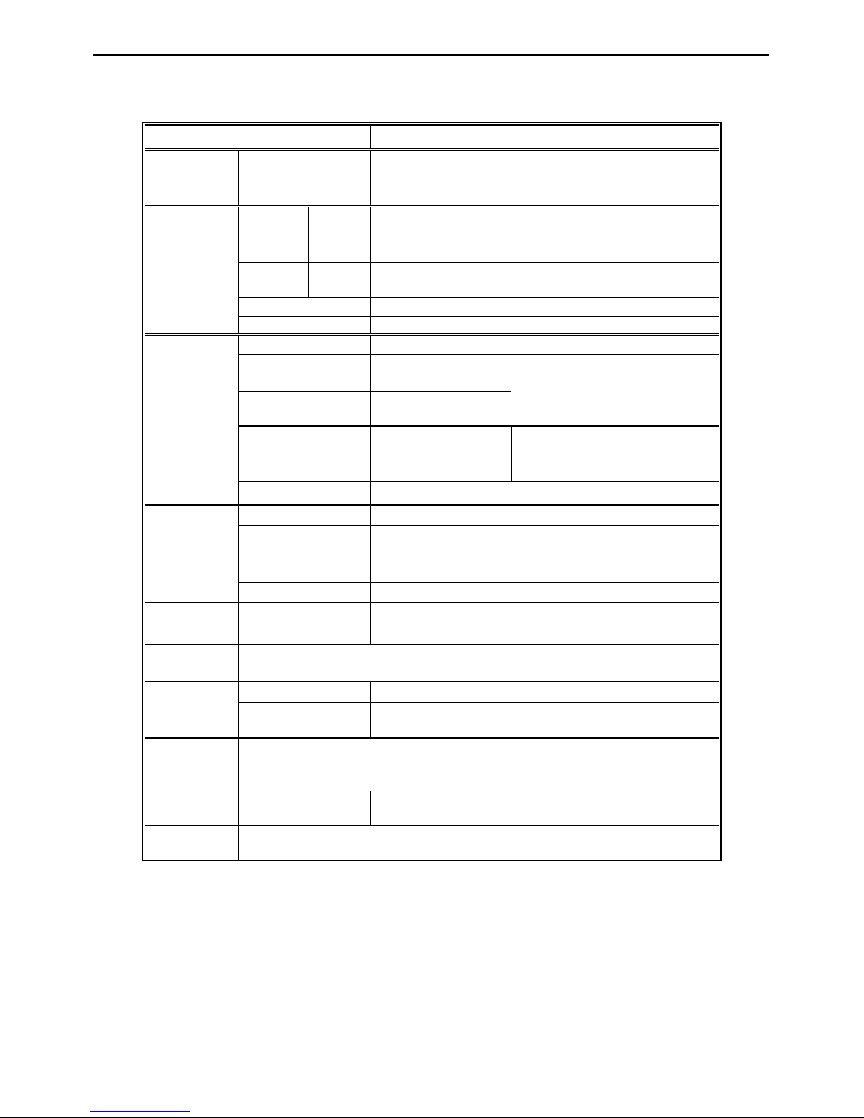
1. General Specifications
Items Specification
LCD Panel
Screen Size 22” TFT-LCD Panel
Resolution 1680 x 1050 pixels
TV Function
TV
Tuning
System
Analog PAL/SECAM
Sound
System
Analog Nicam / A2
Teletext Yes (10 Pages)
Color systems PAL / SECAM
Video Inputs
SCART (RGB+CVBS) x1
AV1 RCA(Composite) x 1
Audio L/R x 1 (Share)
S-Video S-Video x 1
Component
Component x1 (share
with D-sub )
Audio L/R×1 (Share with PC
Audio )
HDMI HDMI x 1
PC mode
Signal input Analog: D-Sub 15 pins (separate)
Plug and play
compatible
DDC 2B
Recommended Analog: 1680x1050 (60Hz)
Audio input Used as a stereo earphone mini jack (3.5 ø)
Audio
Output
Audio output: L/R
Speaker (built-in): 2*3 watt speakers
Headphone: Mini-jack for stereo (3.5ø)
OSD
language
English/French/German/Spanish/Russian/Italian/Finnish/
Swedish/Danish/Norwegian
Power
Power supply 100-240V ~50/60Hz
Power
Consumption
Power-on<75W; Power saving-off<2W
Wall Mount
dimension
VESA: 100*100 mm
Dimension
W x H x D (with
stand)
539mmx447mmx209mm
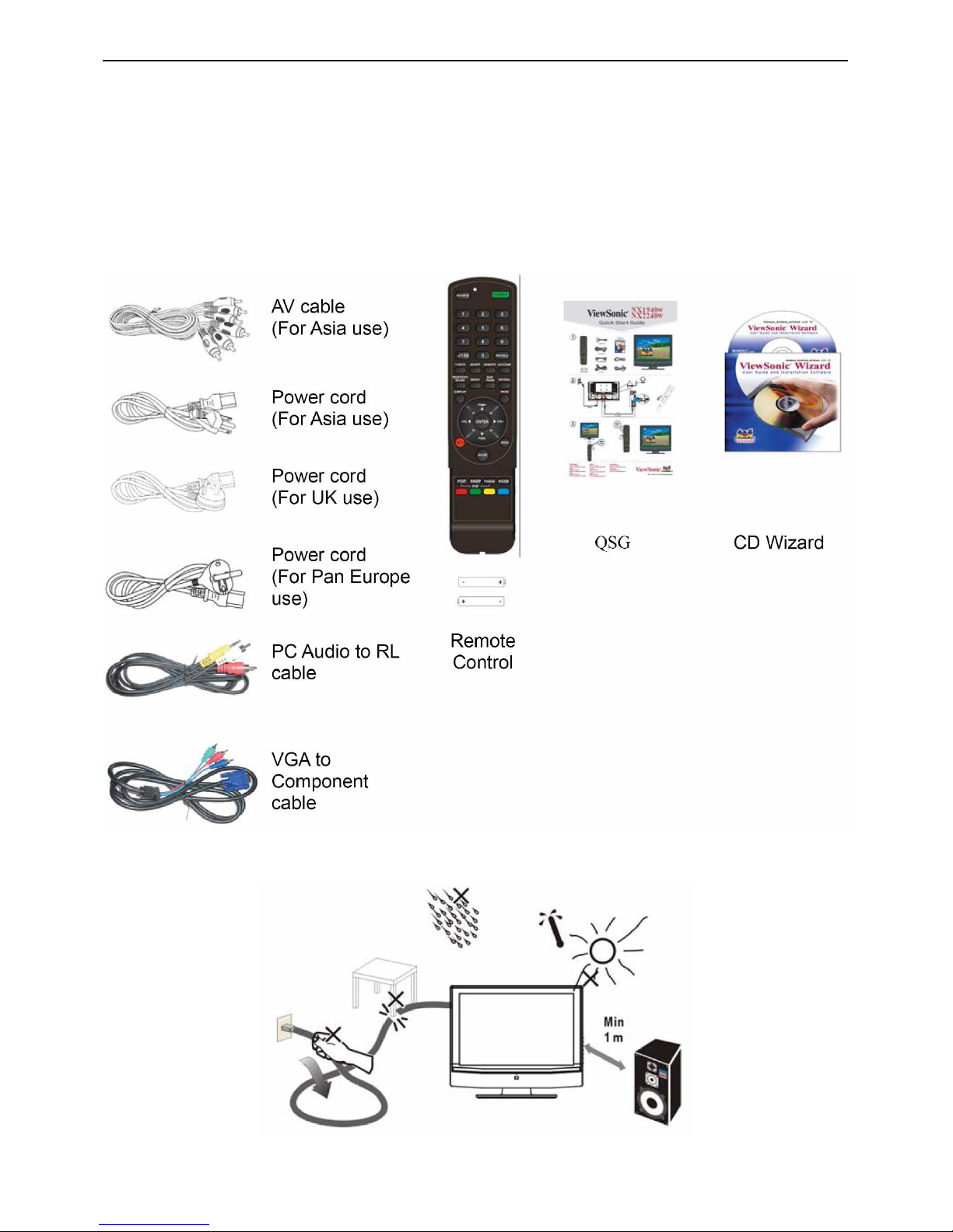
Accessories
Remote Control, Batteries, CD wizard, QSG, AV Power cord, VGA to
Component cable, PC Audio to RL cable, AV cable( for Asia use)
22″LCD TV VSC NX2240w-E
7
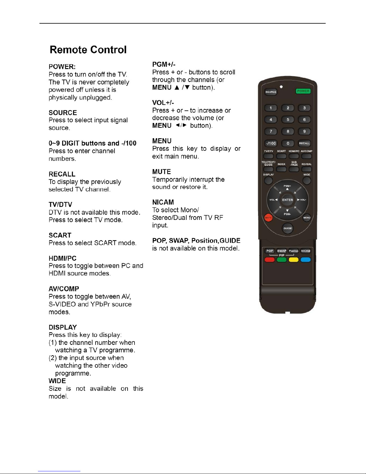
2. Operations Instructions
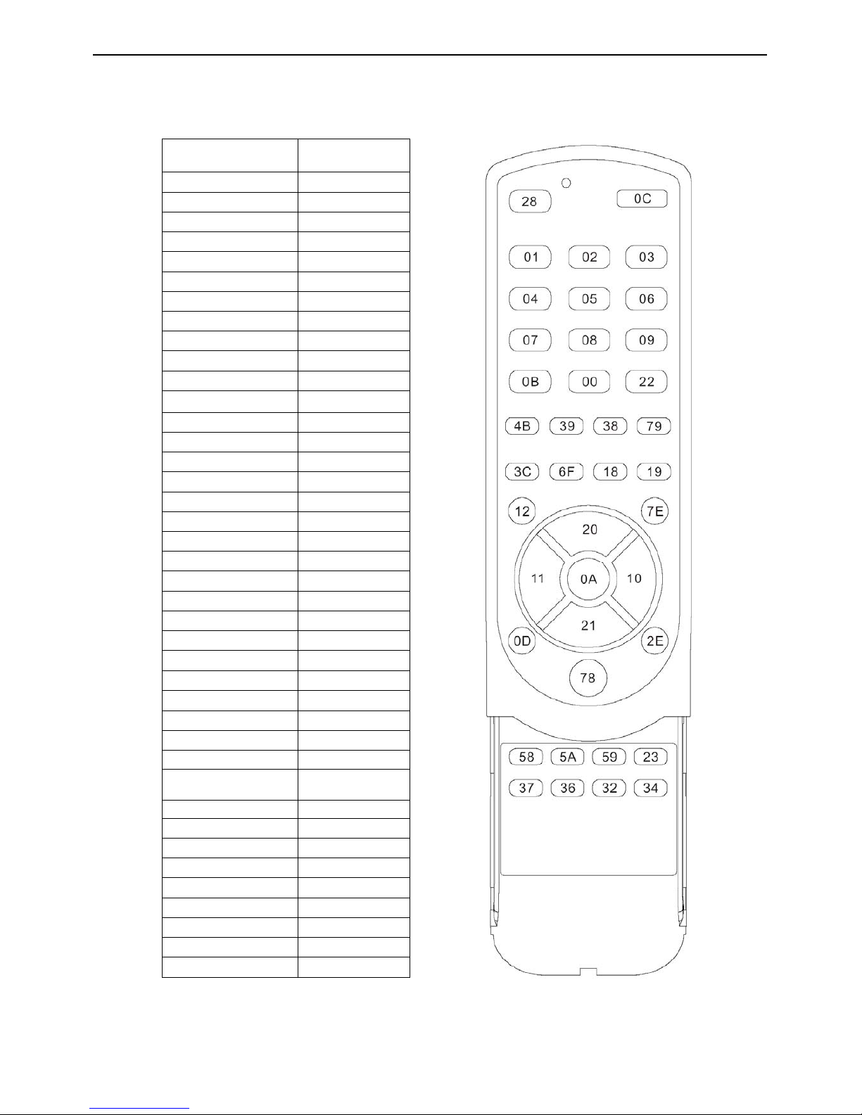
2.1 RCU Code
Key Label DATA CODE
POWER 0C
Vol +/ RIGHT 10
Vol -/LEFT 11
Ch +/UP 20
Ch - /DOWN 21
RECALL 22
Mute 0D
1 01
2 02
3 03
4 04
5 05
6 06
7 07
8 08
9 09
0 00
Enter 0A
Menu/OSD 2E
TELETEX 3C
Guide 78
Source 28
TV/DTV 4B
SCART 39
HDMI/PC 38
AV/COMP 79
Red 37
Green 36
Yellow 32
Blue 34
PIP/POP (PIP/on or
of
58
PIP/Position 59
PIP/SWAP 5A
-/100 0B
Index 6F
Sub-page 18
REVEAL 19
Display 12
NICAM 23
Wide 7E
22″LCD TV VSC NX2240w-E
8
22″LCD TV VSC NX2240w-E
9
22″LCD TV VSC NX2240w-E
10
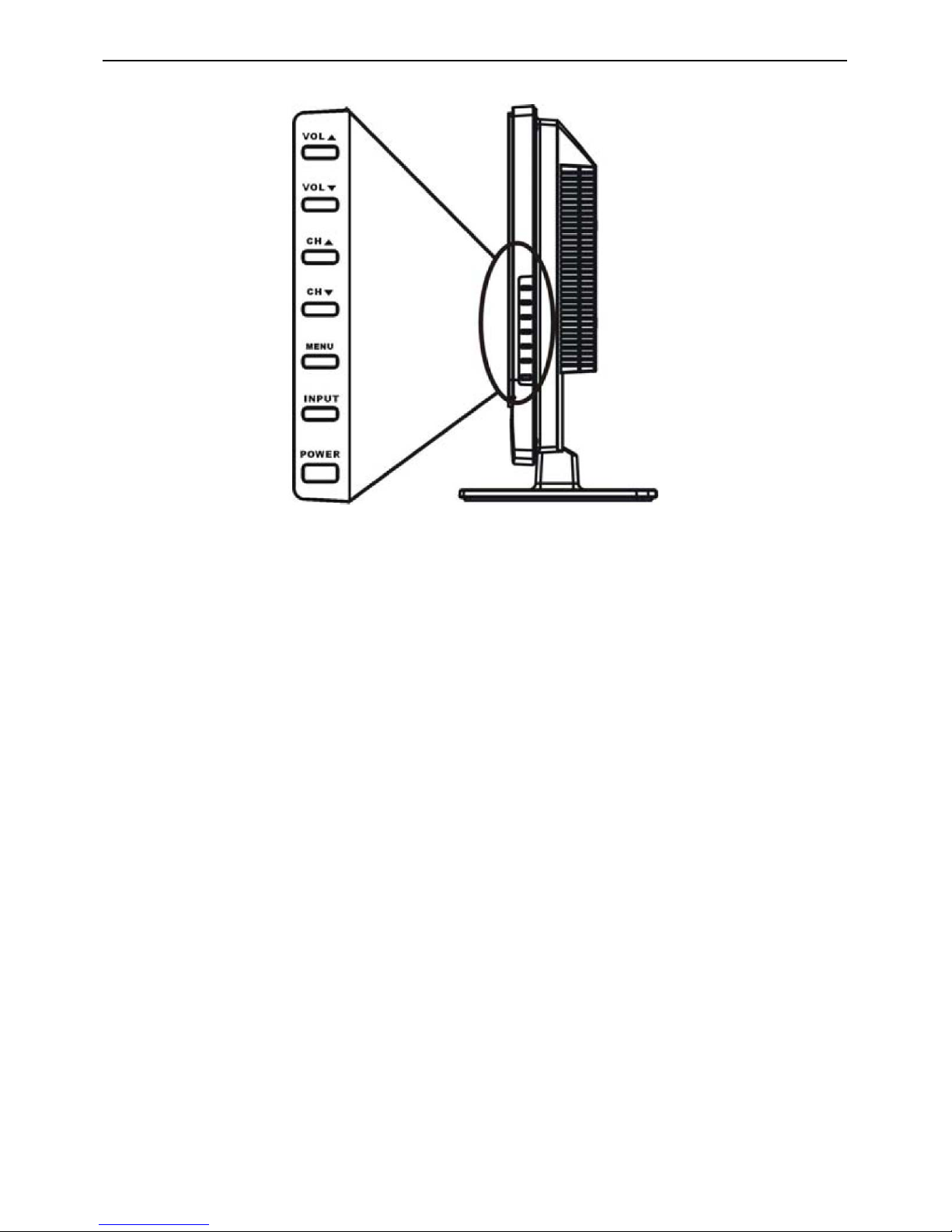
2.2 Front Panel Control Knobs
Vol(▲ ):When the OSD menu appears, press these two buttons to confirm the selected item; when no OSD menu
appears, use to adjust the volume.
CH(▲ ): When the OSD menu appears, press these two buttons to select the item you want to execute; when no
OSD menu appears, use to change channels in TV mode.
Menu : Press this button to display or exit the OSD menu.
Input : Press this button to change input source.
Power : Press this button to turn on the TV or allow the TV to enter standby mode.
If the TV is in standby mode, the indicator at the front will illuminates amber. There is a wide range of video and
audio equipment that can be connected to your TV. The following connection diagrams show you how to connect
them. ViewSonic 12 NX1940w/NX2240w
22″LCD TV VSC NX2240w-E
11
2.3 OSD Operations
To Use the OSD Menu
1. Press the MENU button to display or close main menu.
2. Use the cursor up/down to select a menu item.
3. Use the cursor left/right to enter a submenu or enable/disable the function.
4. Press the MENU button to exit the menu.
Main Menu
Press the MENU button to enter the main OSD (On Screen Display). Adjust the items including Picture Setup,
Sound setup, Function Setup and TV setup. When the input source is AV/S-VIDEO /SCART/YPbPr/ PC/ HDMI
mode, only the Sound Setup, Picture Setup and Function Setup can be selected; shown in the figure below:
When the input source is TV mode, the Sound Setup, Picture Setup, Channel select Setup, Function Setup and TV
Setup can be selected; shown in the figure below:
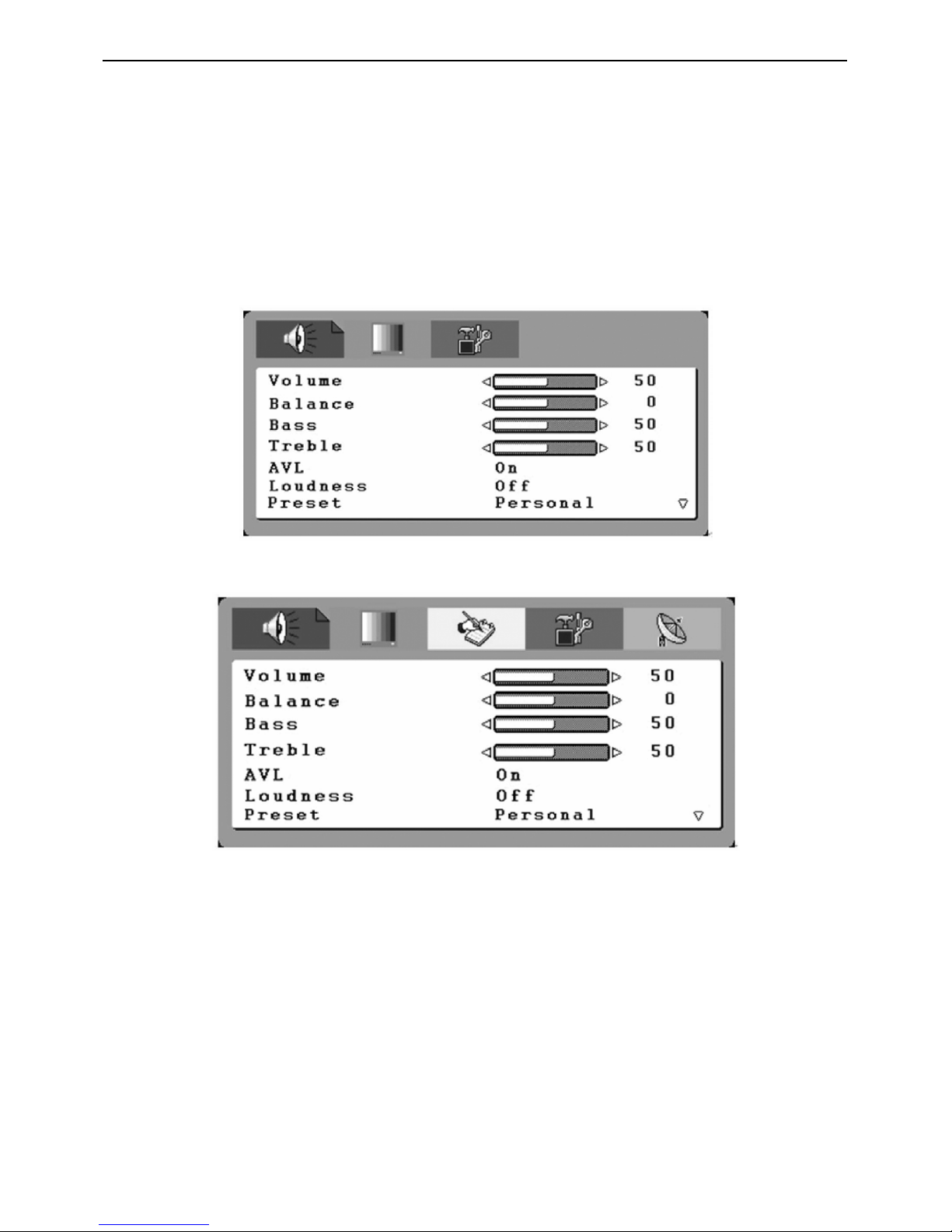
Sound Setup (Same as in TV/AV/S-VIDEO /SCART/YPbPr/ PC/ HDMI)
1. The range of adjusting volume, bass and treble is from 0~100.
2. Bass and Treble: the easy Equalizer function, Bass can adjust the low frequency sound and Treble can adjust the
high frequency sound.
3. The range of adjusting Balance is -50~+50; when adjusting from 0 to -50, the sound from the left track fades until
silence; when adjusting from 0 to +50, the sound from the right track fades until silence.
4. AVL: you can set it “ON” or “OFF”.
The function is to adjust the input sound automatically. You may enable this function when you notice that the sound
in the two tracks are very different, in order to prevent the bad sound effect resulting from large sound variation.
5. Select "ON" or "OFF" for Loudness: a default setting is preset, you may adjust when
necessary.
The following menu will appear when selecting continuously:
22″LCD TV VSC NX2240w-E
12
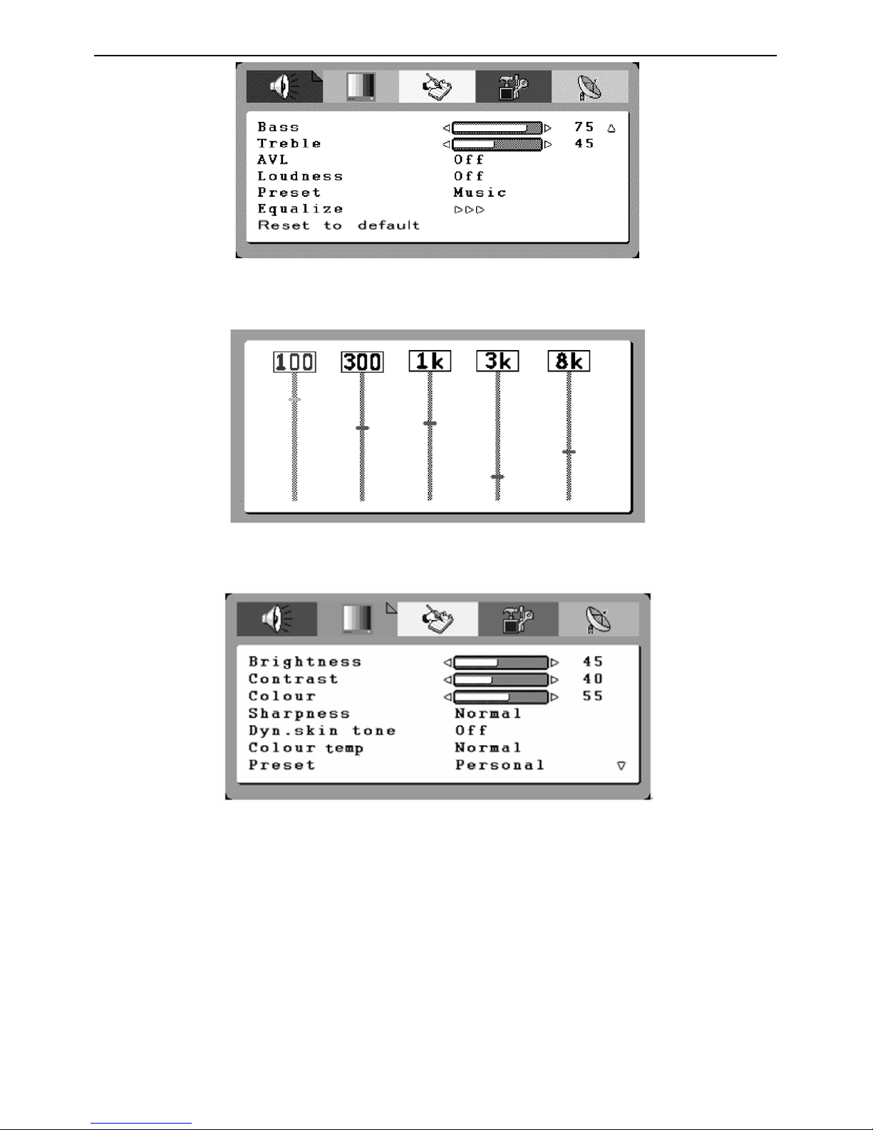
6. Preset: Designed for different types of sound output, where in, the voice music, personal and theatre modes are
preset; you can set Bass, Treble and Equalizer in sound output mode according to your preference.
7. Equalizer: You can select and adjust 100, 300, 1K, 3K and 8K respectively (the figures represent the sound
frequency range).
8. Reset to default: Reset the sound setting to the factory default value.
Picture setup
When the input source is in TV/AV/S-VIDEO /SCART/ YPbPr/ HDMI, you can select Brightness, Contrast, Colour,
Sharpness, Dyn. Colour Temp, preset and Reset to default respectively; shown in the figure below:
When the input source is in PC mode, you can select Brightness, Contrast, Position, Video noise, Sharpness, Auto
Adjust, Info, Colour Temp., Red, Green, Blue and Reset to default.
1. Brightness and Contrast: The range can be adjusted from 0~100.
2. Position: There are two options, Horizontal and Vertical, which can be adjusted from -50 to +50.
3. Video noise: There are two options, Phase and Clock, which can be adjusted from -50 to +50.
4. Sharpness: Select from five options of Softest, Soft, Auto, Sharp and Sharpest. You may adjust the above options
according to your preference.
5. Auto Adjust: Automatically adjust PC input to the optimal screen size.
6. Information: Prompt the current size for PC input definition (only the definition that can be shown by this device).
7. Colour Temp.: There are four options of colour temperature provided for users - normal, warm, cold and User.
You can select the three colour temperatures of normal, warm, and cold, or manually adjust red, green or blue in the
User setting (you can only adjust red, green and blue in the user setting).
8. Reset to default: It is used to reset the picture settings to the factory default mode.
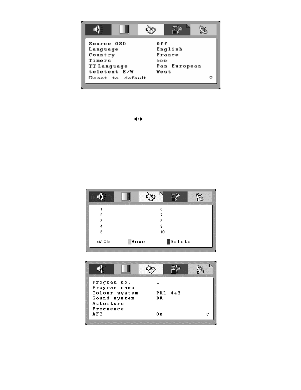
Function Setup
When the input source is in TV mode, you can select Source OSD, Language, Country, ACI, Timers, TT Language,
Teletext E/W and Reset to default; shown in the figure below:
22″LCD TV VSC NX2240w-E
13
1. Current Source OSD setting: When OSD is set to ON, the left upper corner of the display will show the input
source or the TV channel number; when OSD is set to OFF, the input source or the TV channel number will
disappear.
2. OSD language setting: There are ten languages option provided - English, French, German, Spanish, Russian,
Italian, Finnish, Swedish, Danish, Norwegian.
3. Country: Select the relevant country using the
buttons.
4. Timers
(1).Sleep Timer: preset a time so that the set can get into standby mode after that time . And the alert function will
count down when there is one minute left.
(2). Reminder timer: set an alert time so that when the time finished, there will be a warning to remind the user.
5. TT Language. and Teletext E/W:The user can set the teletext language.
6. Reset: It is used to reset the OSD settings. When the input source is in AV, S-Video or SCART mode, you can
select Source OSD, Language, Timers, TT language, Teletext E/W and Reset to default; When the input source is in
PC and HDMI mode, you can select Source OSD, Language, Timers and Reset to default;
TV setup
The following menu appears only in the TV mode.
A. channel select function
This set can give the user a channel list that all channel received
B. channel setup function
1. Programme no. : Shows the current programme number.
2. Programme name:show the programme name, also the user can give the programme a unique name
3. Colour System / sound system: select the colour and sound system the current channel.you can selet ”auto”,the
set will identify it by oneself
4. Auto search: Select "Auto Search" to search all signaled channel; when the searching is complete, it stays at the
first channel with signal and all channels that have been located are stored. If you would like to stop "Auto Search"
during the process, simply by pressing the function button.
22″LCD TV VSC NX2240w-E
14
5. Frequency:show the current signal Frequency
6. AFC can be set to ON or OFF. When it is set to ON, the TV will search the TV signal automatically; when there is
any offset in the signal, it will automatically adjust the channel to the correct position.
7. Skip can be set to ON or OFF. When it is set to ON, a channel can be skipped by pressing the CH button on the
remote control or on the front panel.
8. Reset to default: Reset to the factory default value.
2.4 How to Connect
Congratulations on your purchase of a ViewSonic LCD TV display.
Important! Save the original box and all packaging material for future shipping needs.
Package Contents
Preparation Assembly
1. Place the TV on a solid surface.
22″LCD TV VSC NX2240w-E
15
Ensure that the TV is placed in a position to allow free flow of air. Do not cover the ventilation openings on the back
cover.
To prevent any unsafe situations, no naked flame sources, such as lighted candles, should be placed on or in the
vicinity. Avoid heat, direct sunlight and exposure to rain or water. The equipment shall not be
exposed to dripping or splashing.
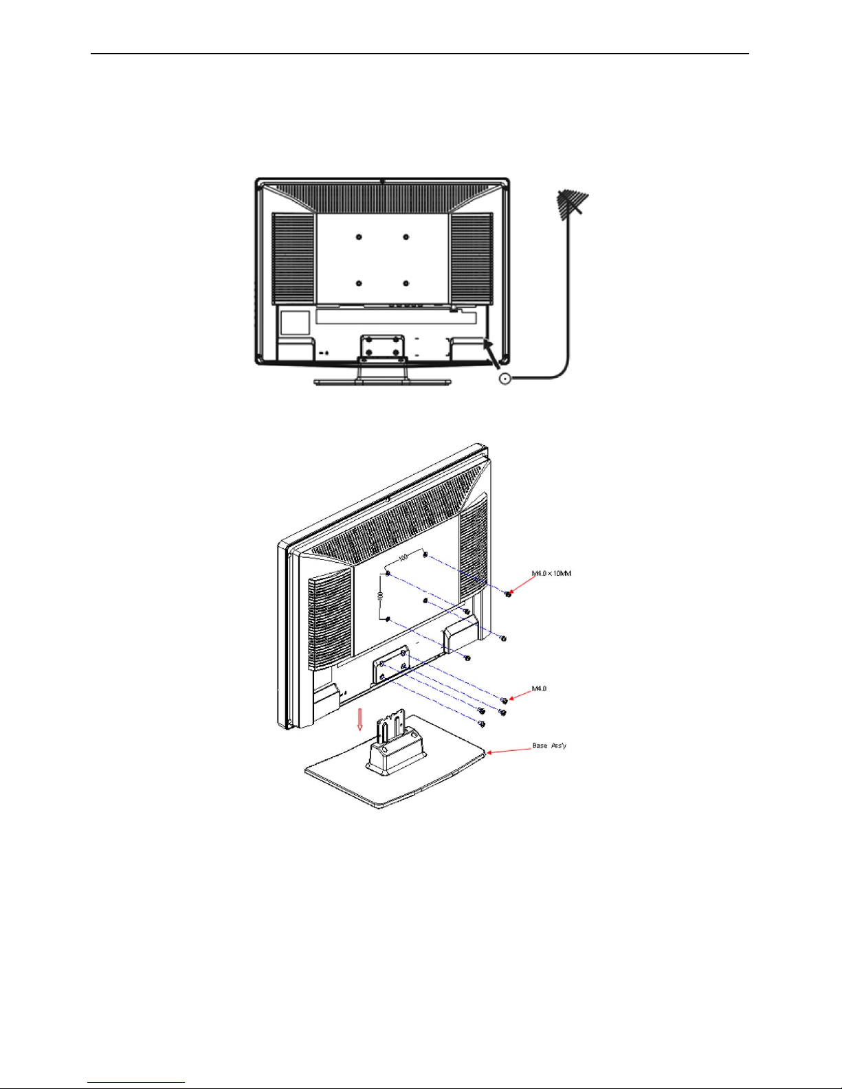
2. Insert the aerial plug firmly into the aerial socket ANT IN 75Ω at the back of the TV.
Wall Mount Bracket
1. Remove the four units M4.0 screws.
2. Remove the Base Ass’y.
3. Fasten four units M4.0 X 10mm screws to secure the wall mount bracket.
Note: If you want to wall mount the TV, for the safety of you and the appliance, please use the correct hanging
brackets. (Wall mounting brackets are not included when you purchase the TV)
22″LCD TV VSC NX2240w-E
16
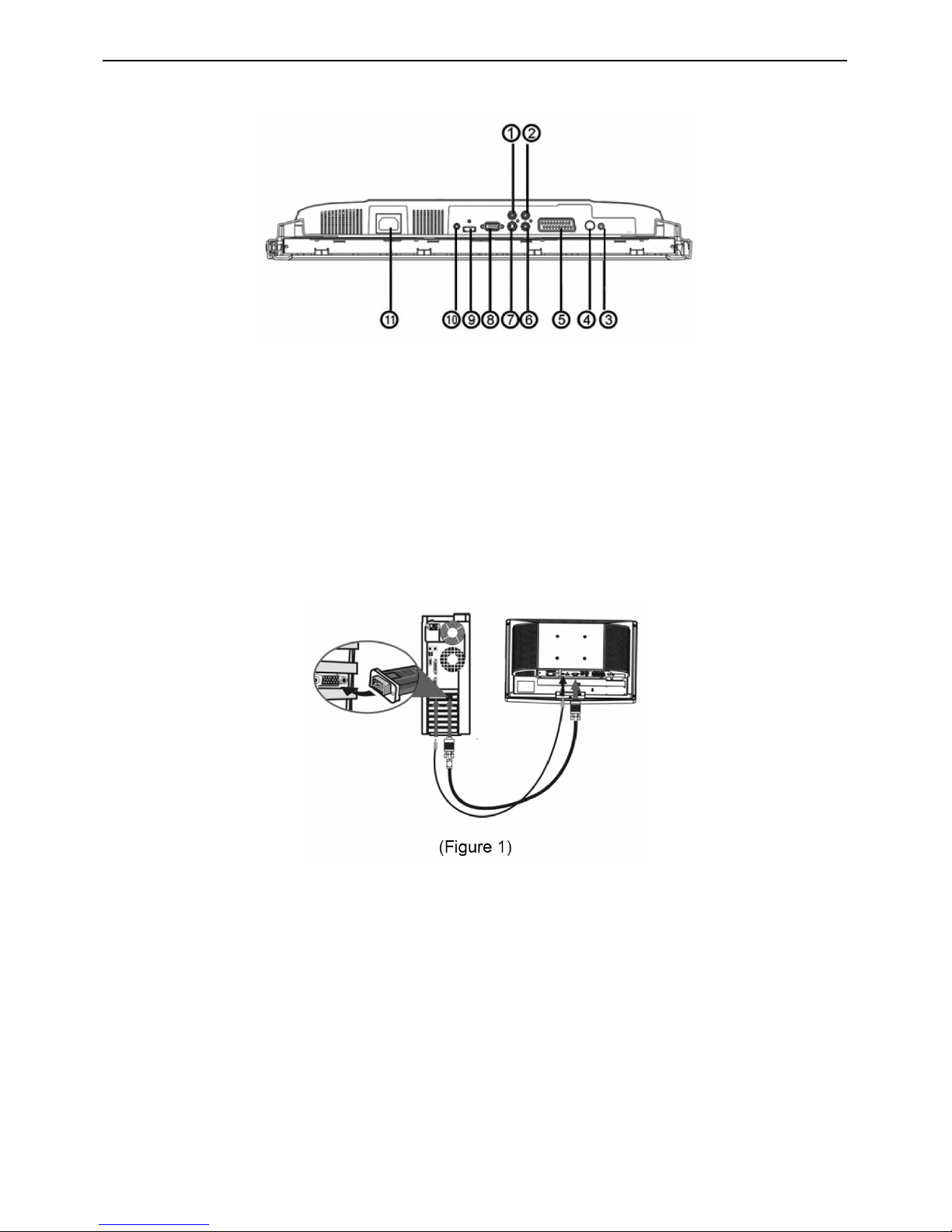
Preparation
Lay the LCD TV with the screen down on a table, as it will be easier to connect your peripheral equipment. Please
take your precautions not to damage the screen.
1: AV1 signal input
2: Right audio track input
3: Headphone outlet
4: TV signal input
5: SCART signal input
6: Left audio track input
7: S-Video signal input
8: VGA input or YPbPr signal input
9: HDMI input
10: VGA audio input or YPbPr audio input
11: AC power input terminal
1> PC input:
Note: For the connection between the PC and the TV, (see Figure 1) below.
(1)How to connect to the PC mainframe:
VGA interface – Connect the VGA signal cable supplied with the TV to the D-sub interface at the rear of the TV as in.
(Figure 1)
(2)How to connect the audio cable:
Connect the PC audio cable supplied with the TV to the TV’s PC Audio Input as in. (Figure 1)
Note: If no signal is present on the VGA screen, the TV will enter into standby mode automatically after 3 seconds.
2> HDMI input:
HDMI is the leading new standard for Digital video and audio interconnection. To the HDMI connector you can
connect HDMI devices such as a Set Top Box or compatible DVD-R or DVD player with HDMI export, or
DVI-equipped devices like a computer. So you can display high-definition pictures on this TV in the digital form.
22″LCD TV VSC NX2240w-E
17
(1) How to use HDMI:
1. Connect one HDMI to the “HDMI” port and connect the other HDMI to device with HDMI export as left
figure.Select the T-Line button, change source button can come into HDMI source.
3. The HDMI connectors allow the following TV and monitor display mod:
SDTV 720x576i, 50Hz /720x480i, 60Hz
EDTV 720x576p 50Hz /640x480p 60Hz
HDTV 1920x1080i 50/60Hz
1280x720p 50/60Hz
VGA 720x480 60Hz
Notes:
1. Your TV supports HDCP (High-bandwidth Digital Content Protection).This is a system for protecting DVD content
outputted via DVI from being copied. It provides a secure digital link between a video source (DVD, PC, etc.) and
your TV. Content is encrypted at the source device to prevent unauthorized copies from being made.
2. Digital devices from different manufacturers have the possibility of different output standards which may cause
difficulties for the television to properly display.
3. In case no signal is detected from your HDMI device, turn off the HDMI device and then on again.
4. To get an optimal viewing, it is advised to turn your DVD player to one of the following
TV display standards: 1280x720p 50Hz.
3> S-Video Input: Connect the S-Video cable to DVD player, Laser Disc player, video
cassette recorder or camcorder.
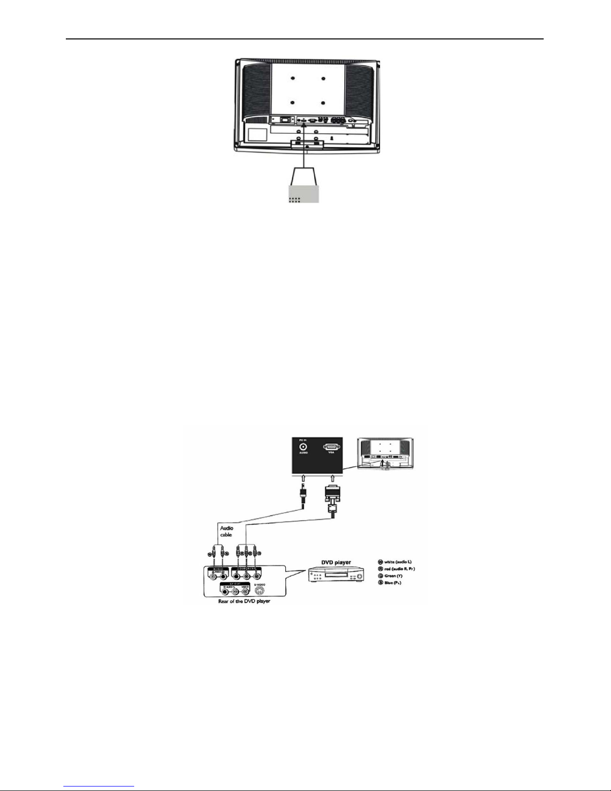
4> YPbPr input:
How to connect a DVD Player or Home Cinema System using Compont Video
Connections:
Connect the Video cable between the D-Sub interface on the unit and Y, Pb, Pr output jacks on the DVD player.
Connect the Audio cable between the Audio input socket on the unit and Audio output jacks on the DVD player.
Notes:
The Y, Pb, Pr output on your DVD palyer are sometime labeled Y, Cb, Cr or Y, B-Y, R-Y. If so, connect cables to like
colors.
5> Audio Input: Connect the audio signal source. (PC, DVD player, Laser Disc player, video cassette recorder or
camcorder) to the Audio Input ports.
6> Video Input: Connect the video signal source. (PC, DVD player, Laser Disc player, videocassette recorder or
camcorder) (The audio is for S-Video and AV)
22″LCD TV VSC NX2240w-E
18
3. Input/Output Specification
3.1 Input Signal connector
This procedure gives you instructions for installing and using the LCD TV display.
Lay the display on the desired operation and plug the power cord into a convenient AC outlet. Three-wire power cord
must be shielded and is provided as a safety precaution as it connects the chassis and cabinet to the electrical
conduct ground. If the AC outlet in your location does not have provisions for the grounded type plug, the installer
should attach the proper adapter to ensure a safe ground potential.
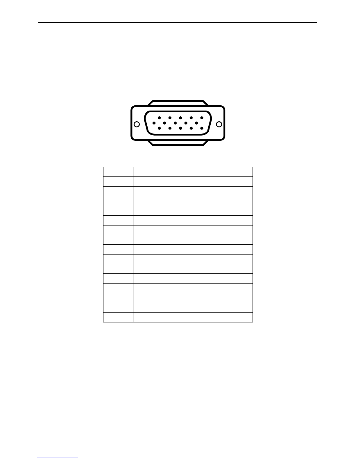
Connect the 15-pin D-SUB color display shielded signal cable to your signal system device and lock both screws on
the connector to ensure firm grounding. The connector information is as follow:
1
6
11 15
5
10
15 - Pin Color Display Signal Cable
Pin No. Description
1 Red Video
2 Green Video
3 Blue Video
4 GROUND
5 GROUND
6 Red Video Ground
7 Green Video Ground
8 Blue Video Ground
9 Mandatory +5V Supply for PC Bypass
10 Sync. Ground
11 G R O U N D
12 Serial Data for DDC
13 Horizontal Sync.
14 Vertical Sync.
15 Data Clock (SCL) for PC Bypass
Apply power to the display by turning the power switch to the "ON" position and allow about ten seconds for Panel
warm-up. The Power-On indicator lights "Blue" when the display is on.
With proper signals feed to the display, a pattern or data should appear on the screen, adjust the brightness and
contrast to the most pleasing display, or press auto-adjust to get the best picture-quality.
This TV (with PC function) has power saving function following the VESA DPMS. Be sure to connect the signal
cable to the PC.
If your TV requires service, it must be returned with the power cord.
22″LCD TV VSC NX2240w-E
19
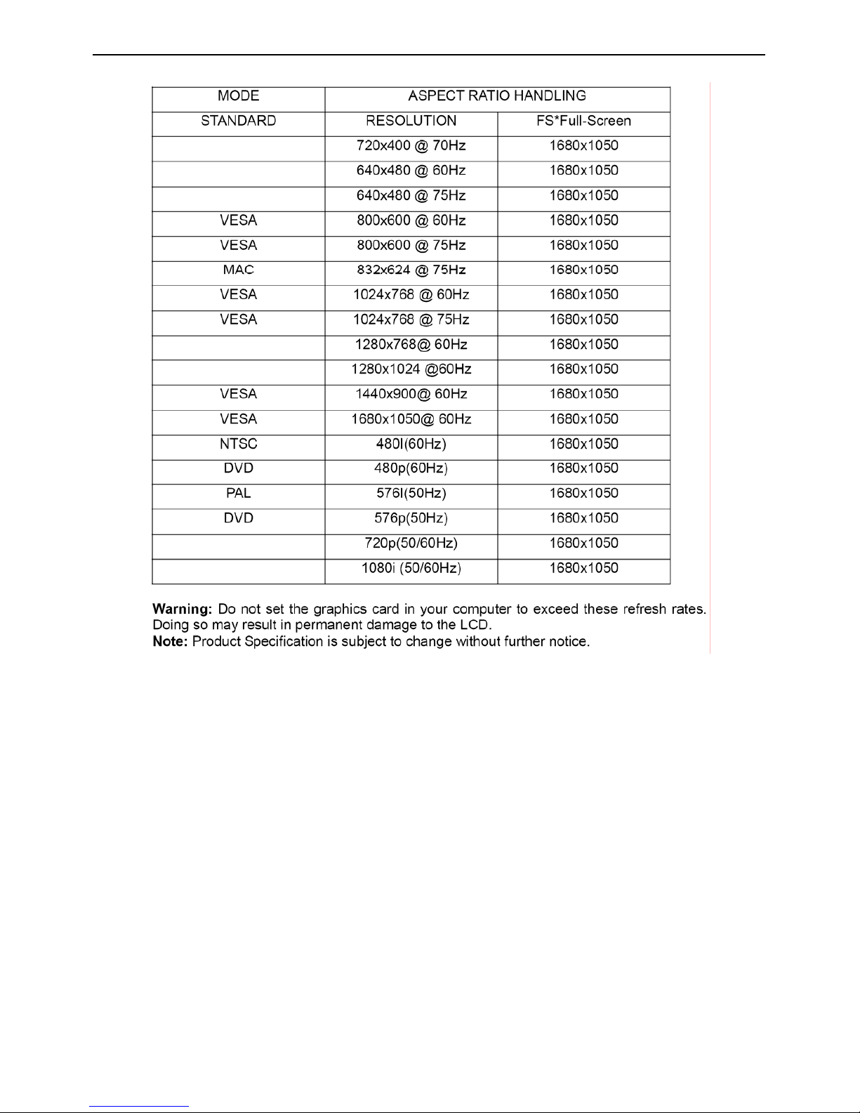
3.2 Factory Preset Display Modes

22″LCD TV VSC NX2240w-E
20
4. Circuit Description
4.1 Description of Main Chips
U401 NT68565HFG/G QFP-128 NOVATEK
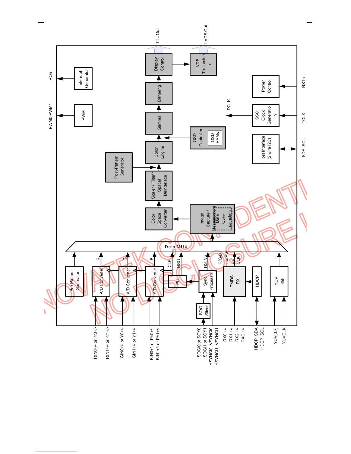
General Description
The NT68565H is a highly integrated flat panel display controller that interfaces analog, digital, and
video inputs. It combines a triple ADC, a DVI compliant TMDS receiver, a digital YUV receiver, a high
quality zoom and shrink engine, a multi-color on screen display (OSD) controller and many other
functions in a single chip. It provides the user with a simple, flexible and cost-effective solution for
various flat panel display products.
The NT68565H operates at frequencies up to 205MHz, suitable for LCD monitor up to UXGA
resolution.
The NT68565H also has a built-in noise reduction function to provide more stable video quality,
spread spectrum to provide low EMI solution, sRGB for video color space convert and post pattern for
manufacture test.
The display provided multi-interface including single pixel clock TTL or single/double pixel clock LVDS
interface.
FEATURES
Analog Graphic Input
♦ Integrated triple high speed ADC/PLL
♦ 0.55V to 0.9V Analog input range
♦ Built-in 2:1 input mux for dual-Analog inputs
♦ Supports both non-interlaced and interlaced input signals
♦ Supports Analog YPbPr input signals clamping, the signals are slightly different from RGB signal in the dc
reference level
♦ 64 steps of phase adjust for each RGB channel
♦ Sampling rate up to 205MHz
♦ 500 MHz programmable analog bandwidth
Digital Graphic Input
♦ Integrated single link DVI receiver
♦ Direct connect to all DVI compliant TMDS transmitters
♦ Operating up to 165MHz
♦ Supports High-Bandwidth Digital Protection (HDCP)
♦ Supports Encryption HDCP secret key
Digital Video Input
♦ Supports ITU-R BT.656 8-bit Input format up to double data rate 1080i
♦ Built-in YUV to RGB color space converter
♦ Spatial de-interlace
Video Processing
♦ Independent horizontal and vertical zoom and shrink
♦ Auto-calibration function for quick video positioning, clock tracking and phase adjust
♦ Programmable H-sync pulse guard window prevents the position detecting errors
♦ Enhancement Back-end brightness, Contrast, Hue, Saturation and Sharpness adjust
♦ Built-in adaptive Noise Reduction function
♦ Built-in Post Pattern generator
♦ Support Bright Frame III function for window media enhancement adjust, that have automatic
contrast & brightness adjustment, color correction and color enhancement on regional picture
Sync Processor
♦ Support TTL Sync-On-Green (SOG) (including Sync Slicer)
♦ Polarity detection
♦ Frequency measurement
♦ Fast mode change detection
♦ Interlace or non-interlace input detection
♦ Separate or composite sync auto switching (including Sync Separator)
Internal OSD
♦ Programmable multi-color RAM font as well as a bitmapped graphical OSD are supported
♦ Provide 184 programmable 1 bits/pixel RAM Fonts, 64 programmable 2 bits/pixel RAM Fonts, 8
programmable 4 bits/pixel RAM Fonts
♦ Optional 10x18, 12x18, 10x16, 12x16 dot matrix
22″LCD TV VSC NX2240w-E
21
♦ Internal SRAM allows up to 2048 characters, with programmable OSD frame size. Width is 64
column, and Height is 32 row
♦ Programmable shadow or border control for each character by each row
♦ Programmable blinking effects for each character
♦ Spacing control to avoid expansion distortion
♦ Supports simultaneous display of up to 8 OSD windows
♦ Maximum 4 times of global zoom for horizontal and vertical axis
♦ Separate row zoom control
♦ Support flexible FG or BG optional transparent, translucent, and opaque effects
♦ 256 palette with 64K color selectable
♦ Top-bottom flip, left-right mirror and 90 degree / 270 degree rotated
♦ Flexible Fade-in, Fade-out effect
♦ Splitting OSD frame supported
Display Output
♦ Supports single pixel or dual pixel output
♦ Multi-output interface LVDS/TTL supported
♦ Support for single pixel clock TTL output up to XGA 75Hz
♦ Spread spectrum clock (SSC) output, output signals drive current and slew rate control for low
EMI
♦ Dithering function supports 24-bit quality for 18-bit panel
♦ Optional Frame Sync or Free Run display synchronization modes
♦ 10-bit programmable gamma correction
♦ 2 channel PWM output for LCD back-light control or volume control
♦ Display resolution up to UXGA
♦ Supports sRGB input
Built-in Dual Pixel LVDS Transmitter
♦ Integrate the Dual Port, 4 Data Channel and Clock-Out Low-Voltage differential LVDS transmitter
to supports single or dual pixel 6/8-bit display data transmission
♦ Suited for VGA, SVGA, XGA and dual pixel SXGA, UXGA display transmission from controller to
display with very low EMI
MCU Interface
♦ High speed serial 2-wire IIC bus
Power
♦ 3.3V power supply
♦ Built-in 3.3V to 1.8V LDO regulator
♦ Normal operate less than 1.5 W
♦ Power down less than 50 mW
Package
♦ QFP 128 pin
22″LCD TV VSC NX2240w-E
22
22″LCD TV VSC NX2240w-E
23
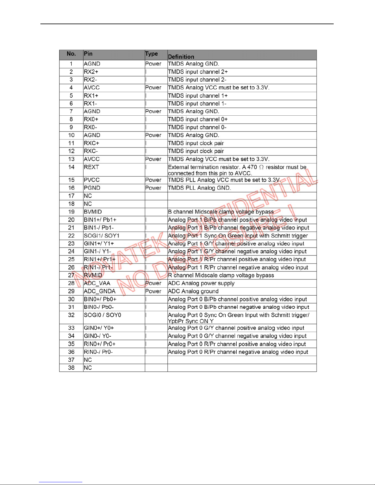
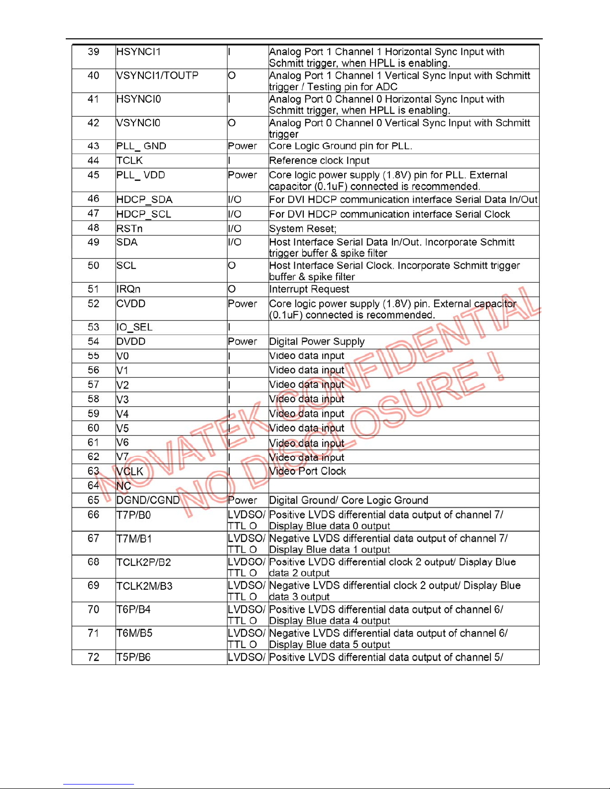
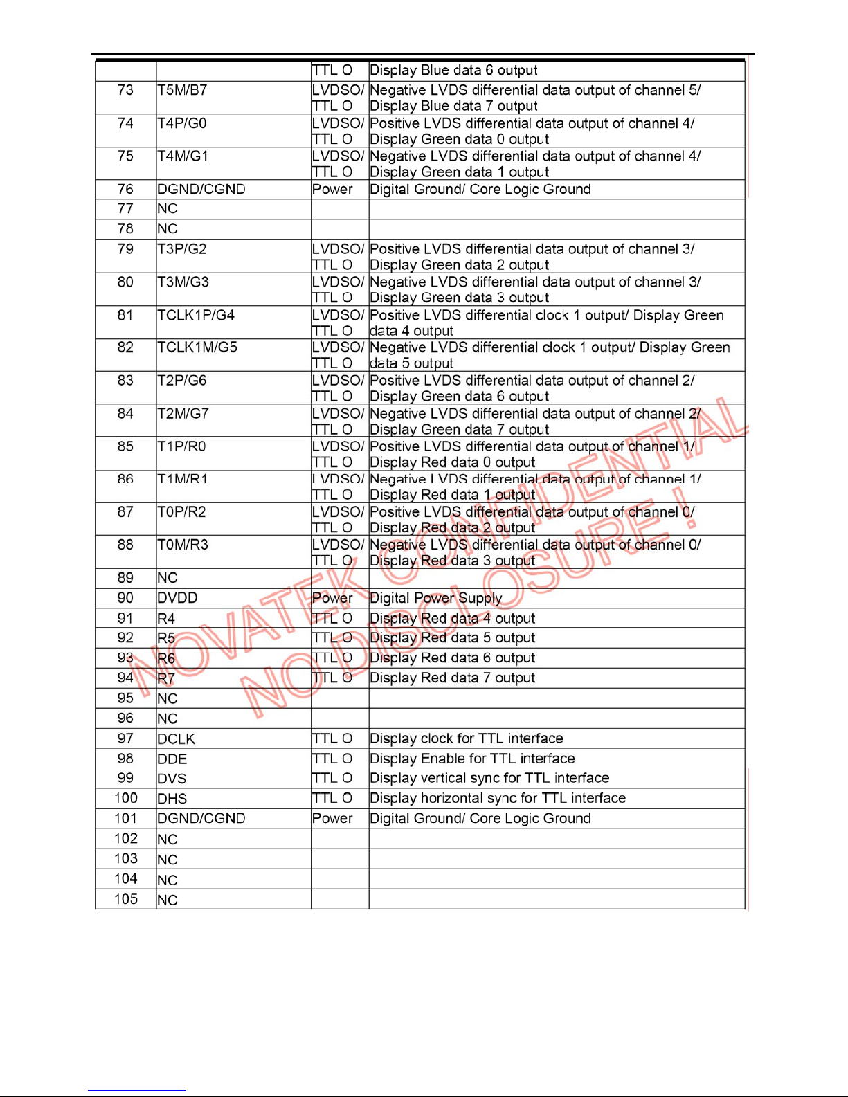
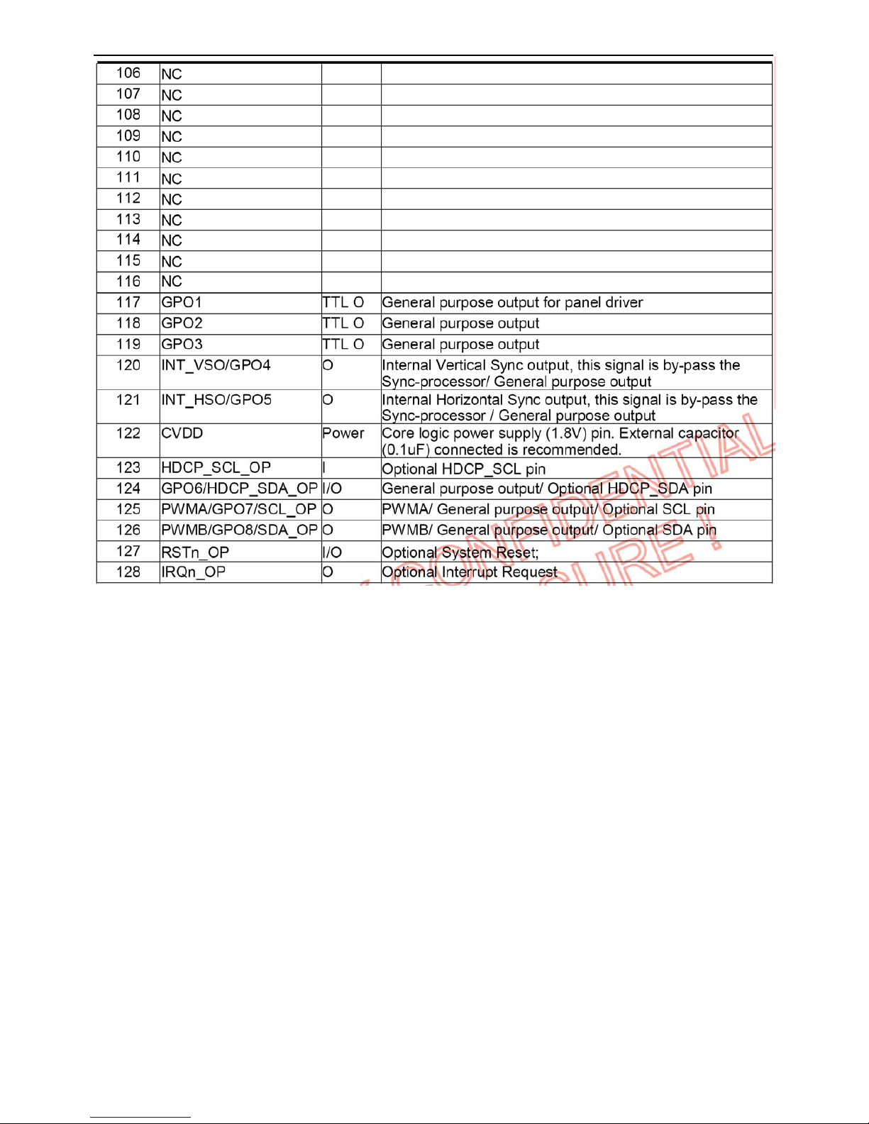
Pin Assignment
22″LCD TV VSC NX2240w-E
24
22″LCD TV VSC NX2240w-E
25
22″LCD TV VSC NX2240w-E
26

22″LCD TV VSC NX2240w-E
27
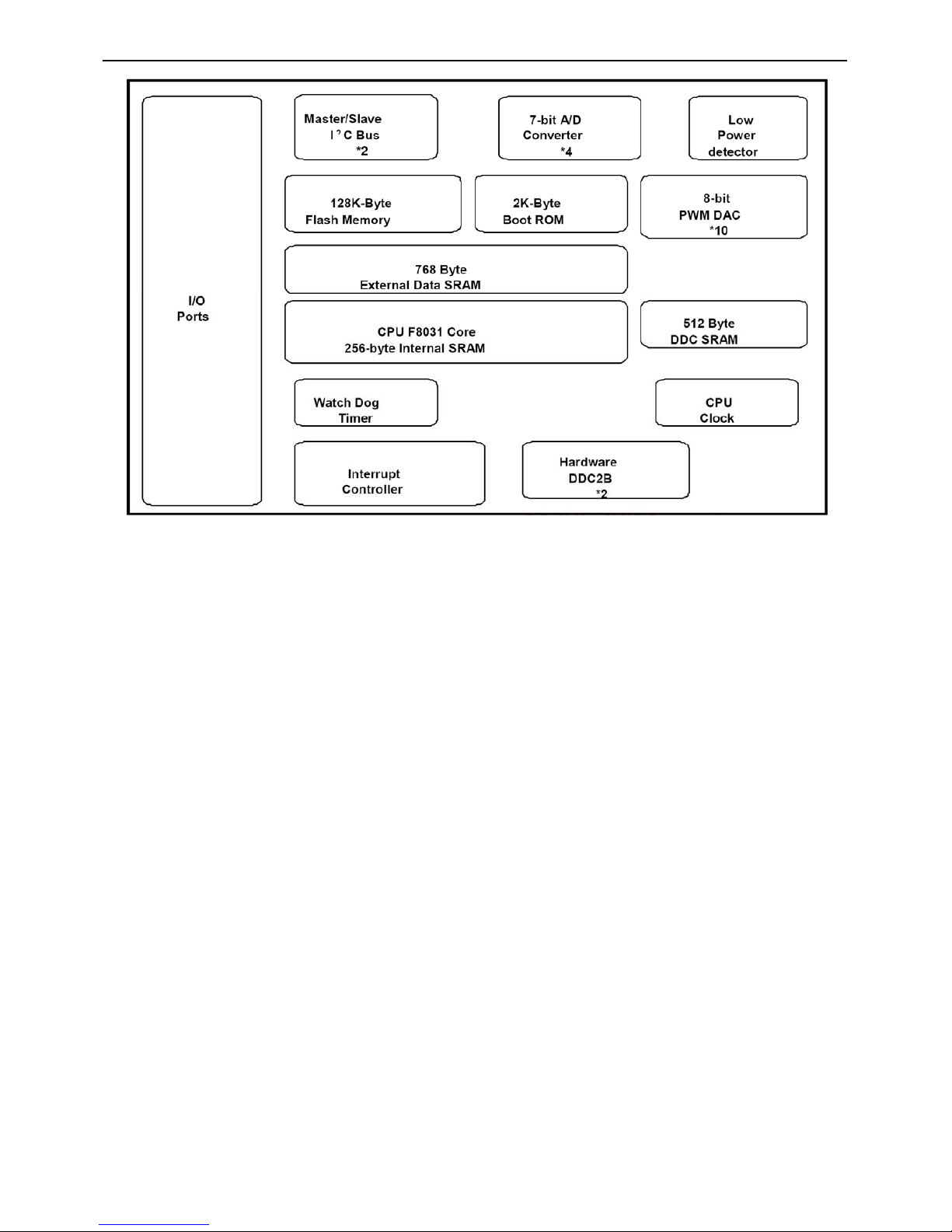
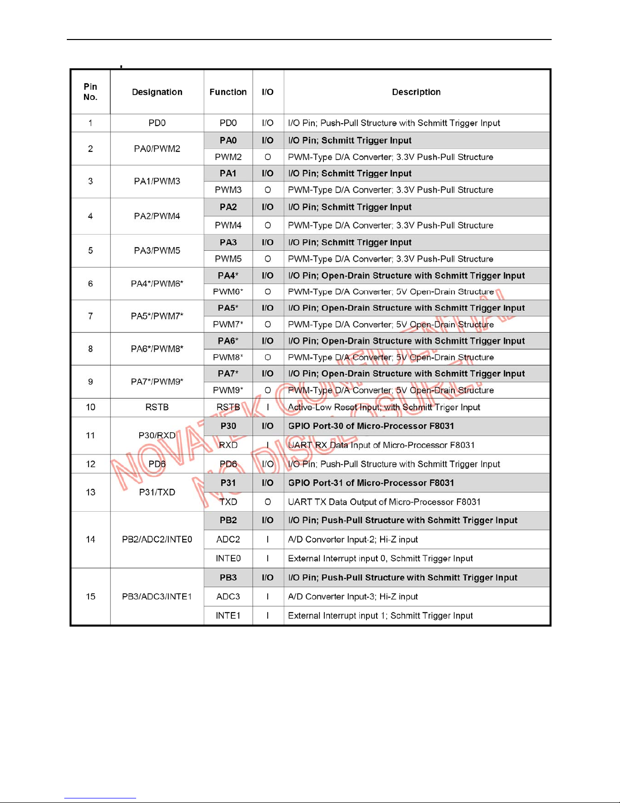
U402 NT68F631ALG PLCC-44
General Description
This is an 8031 CPU core embedded micro-controller, which is design for high-performance low-cost LCD
monitor control application. It contains an 8-bit 8031 micro-controller, on-chip 64K bytes flash-type
program ROM, 1,280-bytes internal data memory, four 7-bit resolution A/D Converter, 10-channel 8-bit
resolution PWM DAC, two16-bit timer/counters, and a UART. Except those, it has two-channel hardware
DDC solution, and VESA 2Bi/2B+ master/slave I2C bus interface. Those functions can help the user to
develop a LCD monitor application as soon as possible.
Features
CMOS technology for low power consumption
Operating voltage Vcc range from 3.0V to 3.6V
8031 8-bit CMOS Micro-Processor (uP) core
– Intel compatible 8031 architecture
– 256-byte Internal DATA Memory
– Two 16-Bit Timer/Counters
– Fully duplex UART
– 5-vector interrupt structure with two programmable priority levels
– High level C-language for the F/W development
On-Chip Oscillator 12MHz~15MHz operating frequency(inlcude 14.318MHz)
24MHz~30MHz clock for CPU operating.
Reset
– External Reset Pin
– Low-Voltage Reset
– Watch-Dog Timer Reset
– ISP Reset
Program memory
– 128K bytes of on-chip flash memory for program memory
– 2K bytes of Mask ROM for ISP control function
1,280 Bytes On-Chip RAM
– Extended 256 Bytes Internal DATA Memory of uP 8031 ($00 ~ $FF)
– External Data Memory
- 768 Bytes General Purpose RAM Buffer ($F400 ~ $F6FF)
- 512 Bytes RAM Buffer for hardware DDC Port ($F800 ~ $F9FF)
A/D Converter
– 7-Bit resolution
– 4 selectable Input channels
– Conversion Range Absolutely Monotonic linear from GND to VCC
– Conversion time under 15us
PWM D/A Converter
– 8-Bit resolution
– 10 selectable output channels
- 6 channels with 3.3V Push-Pull Structure
- 4 channels with 5V Open-Drain Structure
37 Selectable General Purpose I/O Pins
Interrupts 5-vector interrupt structure with two programmable priority levels for uP F8031
– TF0: Timer/Counter 0 Overflow Interrupt
– TF1: Timer/Counter 1 Overflow Interrupt
– RI+TI: UART Interrupts
– INT0:
- I2C Bus Port-0 (PB4, PB5) Interrupt
– INT1
- External Interrupts: INTE0 & INTE1
- I2C-Bus Port-1 (PB6, PB7) Interrupts
DDC Port
– Dual indepentent input DDC channels
– Pure hardware solution for VESA DDC2B
– Selectable 128/256 Bytes EDID-Buffer for hardware DDC port
I2C-bus
– Two built-in master/slave I2C bus interfaces support VESA 2Bi/2B+
– SCL clock speed support up to 400Kbps(24Mhz clock)
Package
– 44-Pin PLCC
22″LCD TV VSC NX2240w-E
28
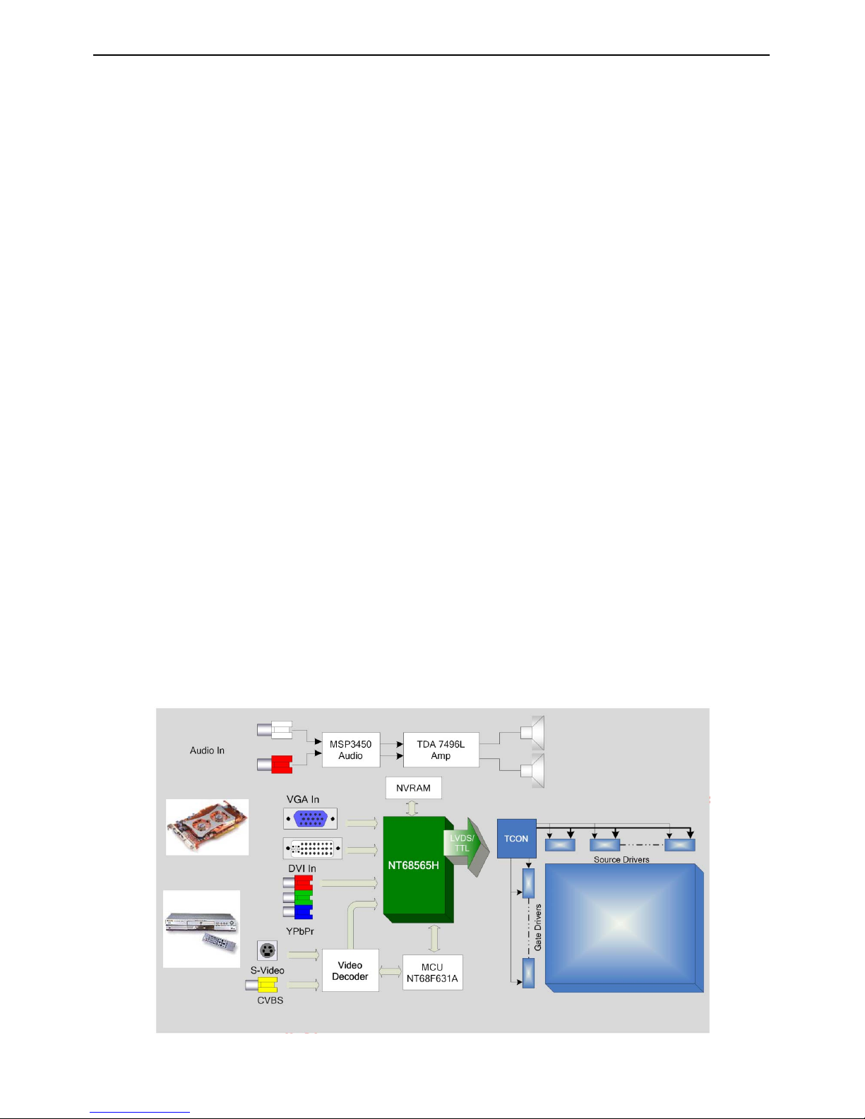
Block Diagram
22″LCD TV VSC NX2240w-E
29
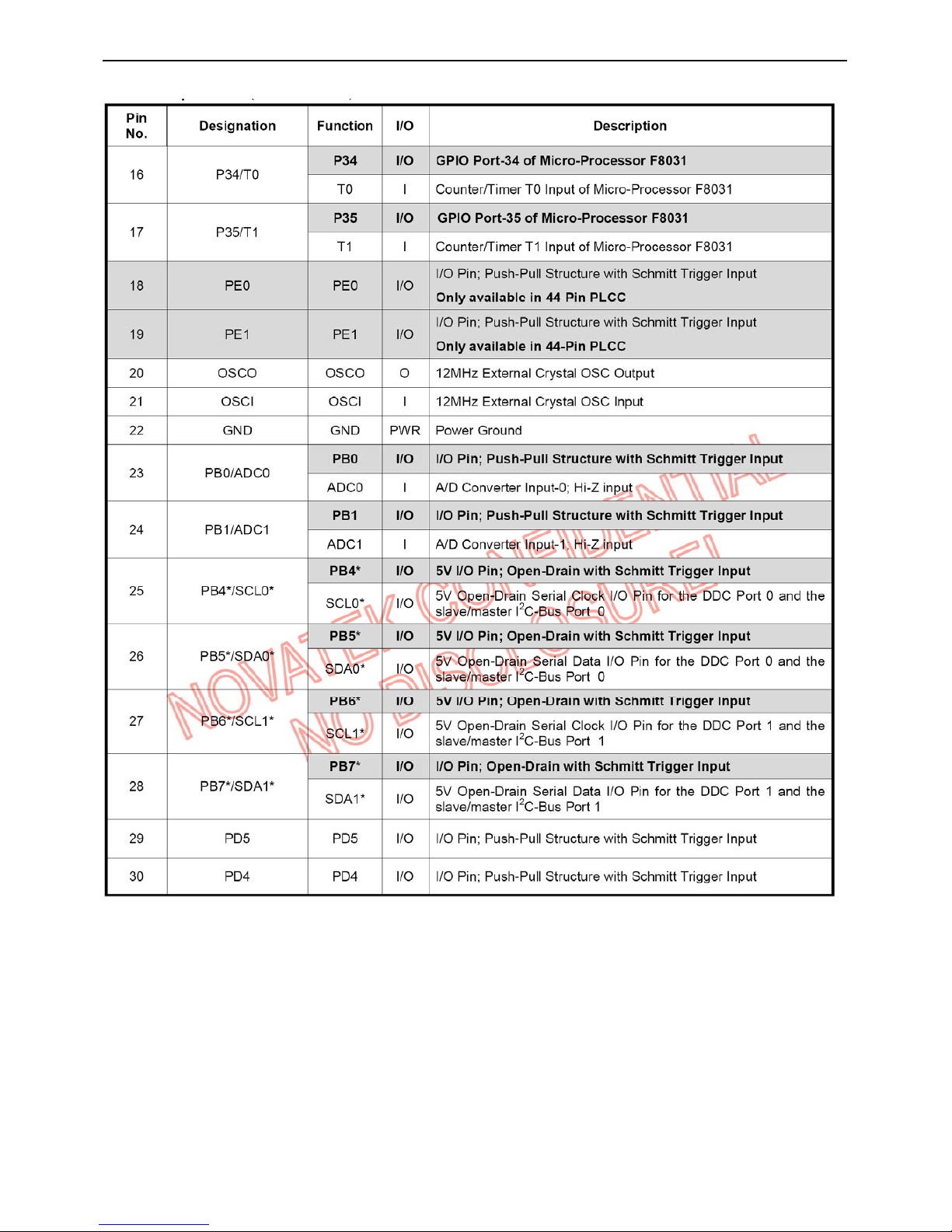
Pin Descriptions
22″LCD TV VSC NX2240w-E
30
 Loading...