

Operating instruction
English translation of original operating
instructions
Documentation
It is imperative to read the operating instructions
prior to commissioning!
This document as well as all documents included in
the appendix is not subject to any update service!
Subject to technical changes.
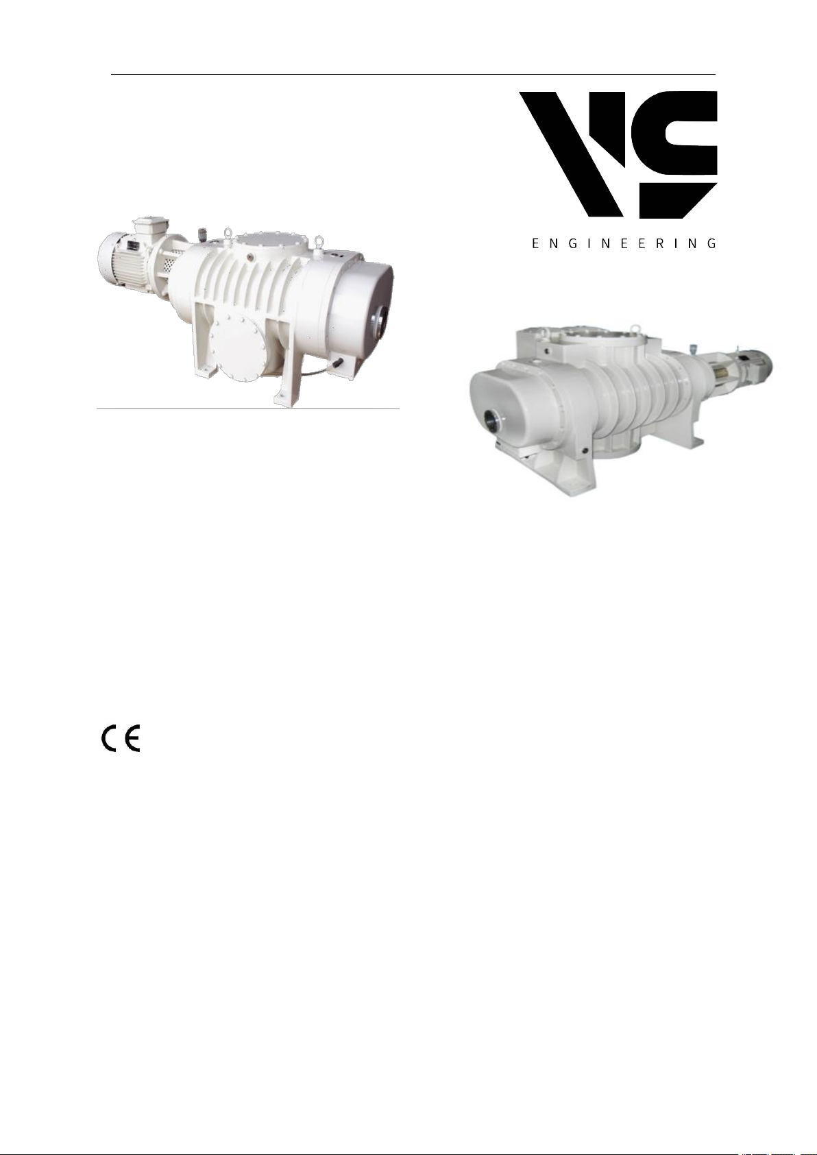
-- ZJ, ZJP Series
Roots Vacuum Pump

ROOTS OPERATING INSTRUCTION
Index
1 Important basic information...................................1
1.1 Statement ......................................................1
1.2 Warranty …………….......................................1
2 Survey .....................................................................2
2.1 Introduction.....................................................2
2.2 Features………………… ................................2
2.3 Usage and model explanation.........................2
3 Performance specification.......................................3
3.1 ZJ pu mp te chni c al data.. ..... . .... . ..... ..... ..... 3
3.2 ZJP pump performance curve ….....................3
3. 3 Pu m p p e r f o rm an c e c ur v e . . . .. .. . . . . . .. . . . 4
4 Operating principle …............................................4
5 Ins tal lation . ........... ............................... ........5
6 Operation...........................................................6
6.1 Prep a rations befor e starti ng.......................6
6. 2 Sta r ti n g.. . .. . .. . .. . .. . ... . .. . .. . .. . ... . .. . .. . .. . .. 6
6.3 Stopp ing……… ......... ..... . .... . ..... ......... . .... . 6
7 Maintenan ce & access ori es .........................6
7.1 Safety information ….....................................6
7.2 Oil change/gear…….....................................6
7.3 Oil change/shaft seal……………….…………..…7
7.4 Cleaning fan………..…………………………...….7
7.5 Cleaning pump chamber………………………….7
7.6 Disassembling & assembling procedure……......7
7.7 replace of mechanical seal..................................8
7.8 Accessories…………………………………………8
7.9 Troubleshooting …………………………………...9
8 Pump structure ................................................11
8.1 ZJ series pump structure………………………...11
8.2 ZJP series pump structure……………………....11
9. Installation drawing …………………………………12
9.1 ZJ series installation size……………………..…12
9.2 ZJP series installation size…………………..…..13

ROOTS OPERATING INSTRUCTION
1
1Important basic information
1.1 Statement
These operating instructions form part of the
technical documentation of the system, and are
addressed to the person in charge of the plant,
who is obliged to provide them to the staff
responsible for the system set-up, connection,
operation and maintenance.
He must ensure that all information included in the
operating instructions and the enclosed
documents have been read and understood.
These operating instructions are the exclusive
copyright of
SHANGHAI EVP VACUUM TECHNOLOGY CO.
LTD
Tel. 0086-21-50878057
Fax 0086-21-50878169
Add: Rm.502 No.1295 Building 1, JINQIAO
EXPORT&PROCESSING AREA, PUDONG,
SHANGHAI, CHINA
Or its legal successor .
Any company or personal can not duplicate,
transfer it to third party, or make illegal business
use. Any operation on the pump should be in
accordance with the instruction.
1.2 Warranty
The manufacture does not accept liability for
damage to persons, animals, objects or
incomplete observance of the safety precautions
included in these operating instructions or by
modifications to the system or use of improper
spare parts.
Warning: Do not move and modify any safety and
insulating device, which may cause great danger.
Warning: The pump can only pump gas. However,
It can not pump any gas that is poisonous,
inflammable, explosive and corrosive, either gas
that reacts with vacuum gas. The pump cannot
used to transit gas. It could be used to pump gas
with few particles, however, it can not pump
Chemicals, condensates, powders and other
granules which will damage equipment, reduce
performance and shorten service life.
Warning: Do not put the pump in rain, steam and
humid air which may cause an electric shock, a
short circuit and the damage of the whole system.
Warning: Whenever changing the wire, please
use qualified wire.
Warning: Use suitable fuses to prevent short
circuit.
Warning: Do not put hands or other stuff into the
pump when it operates. The behavior will cause
bodily injury and damage of pump parts.
Attention: (please ignore if the pump use air
cooling. This is for water cooling type only) The
pipe of the cooling water cannot be obstruct,
otherwise the temperature of pump will be too
high .
Attention: The pump needs regular maintenance;
otherwise there will be damage, or even reduction
of its life. Cut down circuit before check and repair,
and only operate when power is off.
Attention: The temperature of operation
environment should be 5C-40C to prevent the
pump from damaging and shortening the life of
use.
Attention: The pump should be put at safe places
with proper ventilation, solid and flat base , and
clean floor, without corrosive gas. Otherwise, the
pump will be damaged and the life of use will be
shortened.
Attention: please ignore if the pump use air
cooling. This is for water cooling type only) In cold
area, the coolant jacket must be drained after car
stopped. Otherwise the coolant may freeze and
thus damage the pump shell.
ZJ/ZJP Series Roots Pump Operating Instruction

ROOTS OPERATING INSTRUCTION
2
2. Survey
2.1 Introduction
Roots pump have ZJ series and ZJP series. As
the input pressure is between 6.5-65 Pa, the
pumping speed is no less than 70L/s, 150L/s,
300L/s, 600L/s,1200L/s,1800L/s and 2500L/s. It is
a kind of roo t s va c u um pu m p in whic h a
co up le of lobed rotor s tur n lik e 8-s h a p e in
hi gh spee d syn c h ro n ou sl y.Tw o ro t o r s
ro ta t e a n d p r o du c e a s p ir a ti on and exhau s t
wh ic h pri n c i pl e is ju s t li ke a roots bl ow e r.
As it w o r ks in a l o w er pre s s u re , th e fre e
fl ow di st an ce of ga s mole c u l e is lon g e r
an d th e re s i st a nc e of ga s passi n g a sma l l
ga p is m u c h large r. Thus , a bi gg er
co mp re ss i o n ra ti o can be gaine d so tha t it
ca n also b e use d as a b l o we r pu m p . B u t it
ca n no t di s c ha r ge t h e g a s t o at m o sp h er e
di re c tl y and re q u ir e s to be u s e d with a
fo re vac u u m pum p in s e r ie s co n n e ct io n .
Th en th e su c k e d g a s i s disc h a rg e d t o
at mo sp h er e thr o u g h the fo r e vac u u m
pu mp (as chart 1).
Ch ar t 1
2. 2 Featu r e s
(1 )T he r e are d e f in it e ga ps be t w ee n ro to r
an d pum p ' s cav i t y, r o t or an d rot o r wh ic h
ar e not in cont a c t . As a resul t :
a. No f r ic t io n , lo w er po w er co n s um pt io n
th at i s c o m p a re d w i t h an oi l sea l e d
me ch an i ca l v a c uu m p u m p o f t h e s a m e
pu mp in g sp e e d .
b. No Oi l- s ea li ng and lubri c a t io n so as to
av oi d bein g pol l u t ed to the vacuu m pump
by oil steam .
c. It is O K for pum p i ng the g a s with a li t t le
du st .
(2 ) As the ro t o r has a go od geome t r ic
sy m me tr y, i t s rotat i o na l spee d is high e r
th an a co m mo n o i l -s e al i ng me c h an ic al
va cu u m p u m p and at th e same pu mp in g
sp ee d i t has fea t u r es o f sma l l e r vo l u me
an d li gh te r we i g h t.
(3 ) When the p u m p is i n op e r a ti on , t h e re is
le ss v i b ra ti o n an d its vol u m e op e ra t in g
ra ti o is a b o ut kv ≈ 0. 5 .
(4 ) The r e is no com p r e ss io n in the pu m p
th an tha t prod u c ed in a m e c ha ni c al
va cu u m p u m p. So no di s c h ar ge valv e is
re qu i re d bu t ag g lu t in at i ve s t ea m ca n b e
re mo ve d .
(5 ) Th e pump ca n be star t e d qui c k l y an d a
li mi t va c u um c a n be r e ac h e d in a sh o r t
ti me .
(6 ) Whe n the pump is in a co m p re ss io n
sc o pe of 1.3× 10³-1 .3 p a
(1 0- 1 0-2to rr ), i t wi l l hav e a sta b l e pump i n g
sp ee d and qui c k ly disc h a r ge gas so as to
re me dy th e def e c t s o f di ff u si o n p u m p and
oi l- s ea le d me c h an i ca l p u m p wh i c h ar e in a
compre s s io n of 1. 3 ×1 03-1 .3 Pa and a l i t tl e
pu mp i ng s p ee d . So it is su it a bl e fo r a
bl ow e r pump .
Except the above features, ZJP series Roots
Pump has own a relief valve which function is to
control roots pump's differential pressure
between air-inlet and air-outlet. When the
differential pressure is over standard one the
relief valve opens automatically. Because the
pump's inlet-outlet is interlinked, some of gas
returns to the inlet. At this time, the pump
operates in a constant differential pressure.
When the differential pressure is lower than that
of a relief valve, the valve close automatically
(shown as Diagram2)
2. 3 Us ag e and m o d e l ex pl an at io n :
Us ag e : v a c uu m de g a ss i ng , v a c uu m
sm e lt in g , vacu u m he a t trea t i ng et c , in
me ta l lu rg ic a l in d u st r y a n d ca n a l s o b e
us ed in chemical industry., foodstuff, medicine.
electrical manufacture etc. Especially when a
water-ring vacuum pump is used for its fore pump,
ZJ/ZJP Series Roots Pump Operating Instruction

ROOTS OPERATING INSTRUCTION
3
it can extract the gas with large steam. So it is
much suitable for productive procedures of
distillation, evaporation, freezing and drying etc.
Model explanation :
ZJ/ZJP-1200
ZJ--roots vacuum pump; ZJP with relief valve
(overflow valve)
1200--pumping speed1200 L/S
3. Performance specification
3.1 ZJ model Technical data
Model
ZJ-150
ZJ-300
ZJ-600
ZJ-1200
Pumping speed(L/s)
150
300
600
1200
Ultimate
pressure
(Pa)
1stage piston pump as
backing pump
5×10
-2
2 stage piston pump as
backing pump
1×10
-1
Max. allowable diff. pressure(Pa)
8×1035×10
3
Motor rotary speed(RPM)
3000
Suitable motor power(kW)
2.247.5
11
Flange size
Inlet(mm)
100
150
200
250
outlet(mm)
100
150
200
200
Cooling type
Air / water
Ambient temperature for air cool
≤30℃ (please use water cool when ambient temperature over 30℃)
Cooling water consumption(L/h)
120
150
Allowable temperature(℃)
100
Vacuum pump oil
100#
Weight(without motor)(kg)
195
250
760
860
3.2 ZJP model Technical data
Model
ZJP-70
ZJP-150
ZJP-300
ZJP-600
ZJP-1200
ZJP-2500
Pumping speed(L/s)
70
150
300
600
1200
2500
Ultimate
pressure
(Pa)
1stage piston pump as
backing pump
5×10
-2
2 stage piston pump as
backing pump
1×10
-1
Diff. pressure at overflow valve (Pa)
4×1032. 7×10
3
Motor rotary speed(RPM)
3000
Suitable motor power(kW)
1.1
2.247.51122
Flange size
inlet(mm)
80
100
150
200
250
320
outlet(mm)
80
100
150
200
200
320
Cooling type
Air / water
Ambient temperature for air cooling
≤30℃(please use water cool when ambient temperature over 30℃)
Cooling water consumption(L/h)
120
150
Allowable temperature(℃)
100
Vacuum pump oil
100#
Weight(without motor)(kg)
110
205
265
780
880
1350
ZJ/ZJP Series Roots Pump Operating Instruction

ROOTS OPERATING INSTRUCTION
4
3.3 performance curve
4. Operating principle
The pump’s operating principle is shown as
Diagram 3.When the pump is rotating, the gas in
an exhausted container directly enters the space
encircled by two rotor and pump cavity and the
gas entered before is merely encircled by space
Vo(see the shaded parts in Diagram). The mixed
gas in Vo is merely encircled, but not be
compressed and expanded. With the rotation of a
rotor, the rotor’s top reaches the outlet port edge,
the gas in pump’s outlet port will spread to the
space Vo, the mixed gas in Vo will be carried to a
fore pump to be exhausted. Thus, with the rotor’s
continuous operation, more gas will be carried to
outlet port and exhausted by the fore pump. That
is the functional principle of the pump’s volume.
When this pump is operating under a very
low pressure, because of rotor’s high speed
(3000rpm), the linear speed of the rotor’ surface is
near to molecular heat pace. At this time, the gas
impacted on the rotor is brought to an outlet port
with a higher pressure and removed by
beforehand vacuum pump. That is the molecular
functional principle of thin pump.
The combined action by the two principles
makes this pump have features of a big pumping
rate and a stable pumping rate curve in an interval
of 1.3x10³~1.3 Pa.
According to this pump’s characteristics and
different operating condition, different fore pump
can be freely chosen which is not required too
high vacuum, but required to remove corrosive
gas with large steam or little dust. Completed with
a double-stage water-ring vacuum pump and a
piston vacuum pump, the limit vacuum is lower
and its power proportioning is different, too. Our
company can specially design various pump’s unit
according to user’s different requirements and
operating conditions .Welcome to contact us by
call or email.
ZJ/ZJP Series Roots Pump Operating Instruction

ROOTS OPERATING INSTRUCTION
5
Diagram 3. Working Principle
5. Installation
1. Before installation, checking each parts and
make sure there have no damaged, and to see
whether the product is fit to order contract.
2. The pump must be installed in a place of
cleaning, no dust or a little dust and infection
with dielectrics. According to its operating
condition, the pump’s inlet port can be equipped
an anti-dust device (such as an oil-sealed
mechanical pump used as fore pump).
3.The pump’s operating environment temp. is
5-40 ℃ and the max. temperature rise is cannot
exceed 100 ℃.
4. According to operating condition, the pump
can be installed to a cement base or steel frame
base which should be calibrated. Otherwise, it
will be seriously affect the pump’s normal
operation.
5. The gas inlet pipe should be kept sealing,
even a small leakage will affect its vacuum.
6. The length of a pipe is as short as possible,
using less joint and elbow with its diameter less
than its pump’s bore.
7. A flexible soft pipe such as a metal bellows
should be linked between this pump and a fore
pump so as to prevent damaging this pump
because of fore pump’s vibration.
8. It is better to equipped a vacuum valve on the
pump’s inlet and outlet pipes so as to keep the
vacuum of pump cavity after stopping operation.
9. (For water cooling type) A valve should be
installed on inlet pipe for cooling water so as to
regulate water quantity and control the outlet
temperature of cooled water at 20-40℃ 。 Pay
attention to the water temperature not over
40℃ so as to avoid producing sediment in a
water tank.
10. An advance vacuum pump must be used as
this pump’s fore pump which is not used alone.
If an oil-sealed mechanical vacuum pump is
used as its fore pump, the two may be used in
series connection. So this pump is not
suitable for drawing out the gases such as
too much oxygen content, explosiveness,
corrosion to ferrous metal, chemical
reaction to vacuum oil and containing dust
etc. Otherwise, the service life of a fore pump
will be shortening.
(1) (2) (3)
(4) (5)
ZJ/ZJP Series Roots Pump Operating Instruction

ROOTS OPERATING INSTRUCTION
6
6. Operating instructions
6.1. Preparations before starting
① For water cooling type, make sure the
cooling water pipe is open.
② Check there have enough lubrication oil in
end cover A and end cover B, make sure the oil
should be reached to the oil level of oil mirror.
The oil cup of oil sealing should be filled full
usually and keep clean. New pump’s oil must be
changed after operating30 ~ 50 hours. After
then, the oil can be changed according to the
operating condition.
③ If there have dust and other metal powder in
the exhausted gas, anti-dust or filler devices
should be installed in front of air inlet port. If
there have corrosive gas in exhausted gases,
some neutralizing measures should be adopted.
④ Check there have no any loosening in
various parts .Motor ’s rotational direction
should be in accordance with arrow direction on
a pump.
6.2. Starting
①Start the fore pump
②Open the gas inlet valve of this pump
③
For water cooling type, o
pen the water cooling
valve and start this pump.
④The pump should be in a stable operation and
the rotor without crash . Or should be stopped.
⑤There is no leakage in the oil –sealed position
of a pump’s shaft.
⑥During the operating, if the temperature rise is
too high ,the reading of current meter is
suddenly changed, an abnormal noise or other
unusual phenomena appears ,the pump should
be stopped immediately.
6.3. Stopping
① Close gas inlet valve which on inlet port at
first.
② Stop pump(and close the inlet valve )
③ Stop the fore pump
④ For water cooling type only, close the water
inlet valve of water cooling pipe.
⑤ If the pump’s operation is stopped for a long
time or its operating in a cold zone, the cooling
water must be drained out completely.
Otherwise, the cooling water will be frozen and
make the pump’s castings in frost crack.
7. Maintenance & accessories
7.1 Safety information
The safety information was given in the
following applies to all maintenance work.
Warning: Disconnect the electrical power before
disassembling the pump and venting to
atmospheric pressure. Make absolutely sure that
the pump cannot be accidentally started. If the
pump has been pumping harmful substances,
determine the nature of hazard and introduce
suitable safety measure.
When drying or blowing out the pump with
compressed air, technician must observe and
obey all safety regulations.
Caution: All maintenance and cleaning work
described in this section must be only carried out
by the trained person.
When handling the used oil pls observe the
relevant environment regulations.
Improper maintenance or repairs may affect the
service life and pump performance.
7.2 Oil change/gear box
Warning: Before pumping oxygen or other highly
reactive gases at concentrations which exceeding
20% in the atmosphere will be necessary to
choose a special pump. Such a pump have to
modified and degreased as well as a special
lubricant oil . Bearings consume a little oil and the
gear under clean operating conditions. We
recommend you to change the oil after the first
500hrs operation to remove any wearing residue.
Then, under the normal operating conditions,
change pump oil after every 3000hrs operating.
Change oil much more frequently when pumping
corrosive vapors or large amount of dust or when
happing from the atmospheric pressure to working
pressure usually.
Warning: Before removing the oil-drain/oil filling
screw, the pump should be stooped at first and
vent to atmosphere pressure( have no vacuum
inside pump chamber).
When the pump has become warm during
operation, the casing and the oil temperature may
exceed 80 ℃ ,then should leave the pump to
cooling down.
Always wear protective gloves to protect yourself
against aggressive residues in the oil .
ZJ/ZJP Series Roots Pump Operating Instruction

ROOTS OPERATING INSTRUCTION
7
Loosen the oil-drain/oil-fill screw and then drain
out the oil. Clean the sealing surface and firmly
reinstall the oil-drain screw using a gasket which
is in a perfect condition. Wipe off any oil residues
from the casing. Fill in new oil. Make sure to use
the right kind of oil.
Caution: We recommend the vacuum oil is N100
or N62. Make sure the oil level is correct .If the oil
level is too low, the bearings and gearwheels will
not lubricated adequately; if it is too high, oil may
enter into the pump chamber. Clean the oil-fill port
and reinstall the screw using a gasket which is in a
perfect condition.
Caution: The oil fill port must be sealed tightly.
Or the air willbe entered into pump chamber
through impeller seals .
7.3 Oil Change/Shaft Seal Housing
Warning: The oil in the shaft seal housing should
be changed every 3,000hrs operating. Loosen the
oil-drain screw under the shaft seal housing, drain
out the oil and then screw the oil-drain with a
gasket which is in a perfect condition. Fill in fresh
oil through the oiler and the oil should be reached
to the oil level. .
Maximum level:
- when the pump is warm = 1/2 of the height
of the oiler.
- when the pump is cold = 1/3 of the height of
the oiler. Wipe off any oil residues from the casing.
7.4 Cleaning the Fan and the Cooling Fins
Warning: The fans slits as well as the motor fins
will be polluted when working in humidity
conditions . In order to ensure a sufficient air enter
into motor and the pump’s casing, the fan grids
must be cleaned using a cleaning brush when
polluted. Any coarse dirt must be removed from
the motor fins and the pump.
7.5 Cleaning the Pumping Chamber
Warning: Under dirty operating conditions, pump
chamber and rotor will be getting polluted. After
removing the two connecting lines, the
contaminants can be blown out with dry
compressed air or flushed out using a suitable
solvent. Contaminants that cannot be removing
completely from the pump chamber with a wire
brush, metallic sponge or scraper. Then change
the oil.
Warning: During cleaning, the rotors must be
turned only by hand. The loosened parts must not
remain in the pump. After cleaning, check the
pump by slowly turning the rotor. The rotor should
be moved freely and without any resistance.
7.6 Disassembling and Assembling procedure
7.6.1 Disassembling procedure :
7.6.1.1 Loosen screw and take down End cover B
7.6.1.2 Loosen screw (ZJ/ZJP70-ZJP600) or
using hydraulic gear device (for ZJ/ZJP1200-2500)
to take down gear.
7.6.1.3 Loosen screw and take down the gear
cover, bearing, bearing seat B, piston ring and
piston ring cover.
7.6.1.4 Loosen screw and take down locating pin,
and then disassembling side cover B.
7.6.1.5 Loosen screw and take down the
motor ,disassembling coupling.
7.6.1.6 Disassembling the locknut in the
active/driven shaft.
7.6.1.7 Take down the shaft, rotor from the side
cover B direction.
7.6.1.8 Disassembling the check ring, bearing
cover, bearing seat A, side cover A, piston ring
and piston ring cover.
7.6.2 Assembling procedure:
Checking all the disassembled spare parts
carefully , change spare parts if damaged . Clean
parts using petrol, diethyl ether or CCI4.
Assembling all parts after dried . The pump body
and side cover should be sealing in plane.
Assembling procedure is an opposite of
disassembling procedure. Technician should
adjust the end cover clearance.
NOTE: Assembling the active/driven gear of
ZJP1200/2500 should be using hydraulic gear
device, using fastener to make sure the gear end
cover come to the bearing end cover at first, and
then depressurization the oil pump.
ZJ/ZJP Series Roots Pump Operating Instruction

ROOTS OPERATING INSTRUCTION
8
7.7 Replace of mechanical seal (for air cooling type only)
Mechanical seal belongs to easy-wearing parts, it should be replaced when the oil / air leakage occurs.
Followed is the disassemble step:
a. Loosen the bolt, remove the static ring base (include static ring)
b. Disassemble screw ( as per diagram 4, this screw is dynamic ring disassembling and assembling
hole).
c. Use a inside 4mm hex wrench to loose the set screw ( 2 pieces), remove the whole dynamic ring.
d. Obey the contract sequence while install the mechanical seal (C--B--A).
Please check and repair the mechanical seal as followed step:
a. Loose the bolt, disassemble the static ring base (include static ring), remove the static ring to check.
b. Remove the dynamic ring seal to check.
7.8 Accessories
Model
ZJP70
ZJ/ZJP150
ZJ/ZJP300
Reinforced seal
40*57*10(1PC)
30*50*10(2PCS)
30*50*10(2PCS)
O-ring
70*4(1PC)
100*4(2PCS)
115*3.5(3PCS)
18*24*4(5PCS)
170*5.7(3PCS)
18*24*4(5PCS)
Model
ZJ/ZJP600
ZJ/ZJP1200
ZJP2500
Reinforced seal
55*75*12(2PCS)
60*80*12(2PCS)
70*95*12(2PCS)
O-ring
220*5.7(3PCS)
18*24*4(5PCS)
220*5.7(2PCS);
270*5.7(1PC);
18*24*4(5PCS)
18*24*4(5PCS)
270*5.7(1PC)
340*5.7 (2PCS)
Diagram 4. Mechanical Seal Installation Structure
ZJ/ZJP Series Roots Pump Operating Instruction

9
7.9 Troubleshooting
Fault
Possible cause
Remedy
Pump does
not start.
Motor is connected incorrectly.
Connect the motor correctly.
Faulty pressure switch.
Replace the pressure switch.
Oil is too thick.
Change the oil or warm the oil and the pump.
Motor rotor is malfunctioning.
After sales service.
Pump has seized up: damaged impellers,
bearings or gearwheels.
After sales service.
Pump gets too
hot.
Ambient temperature is too high or cooling
water supply is obstructed.
Install the pump at a suitable site or ensure
enough cooling water.
Pump is working in the wrong pressure
range.
Check pressure values of vacuum system.
Pressure differential is too great.
Check pressure values of vacuum system.
Gas temperature is too high.
Check the vacuum system.
Clearance between casing and impellers is
too small due to:
- contamination
- distortion of pump.
Clean the pumping chamber.
Ensure that the feet and connecting lines
aren’t placing a strain on the pump.
Excessive frictional resistance due to
contaminated bearings and/or oil.
Exchange oil.
Oil level is too high.
Drain some oil to reach the correct level.
Oil level is too low.
Add oil to reach the correct level.
Wrong oil has been used.
Drain oil and fill in correct lubricant.
Bearing are malfunctioning.
After sales service.
overflow valve does not open.
Clean or repair the valve.
Power
consumption
of the motor is
too high.
See fault “pump gets too hot”.
See fault “pump gets too hot”.
Wrong mains voltage supply for the motor.
Connect the motor to the correct voltage
supply.
Motor is malfunctioning.
Repair the motor or exchange it.
Oil is too thick.
Exchange the oil or warm up the oil and the
pump.
ROOTS OPERATING INSTRUCTION
ZJ/ZJP Series Roots Pump Operating Instruction

ROOTS OPERATING INSTRUCTION
10
Fault
Possible cause
Remedy
Pump is too
loud.
Clearance between casing and impellers
is too small due to:
-contamination
-distortion of pump.
Clean the pumping chamber.
Ensure that the feet and connecting lines aren’t
placing a strain on the pump.
Bearing or gearing is damaged.
After sales service. Switch off the pump at once.
Impellers strike the casing.
After sales service. Switch off the pump at once.
Rotor runs out of true.
After sales service. Switch off the pump at once.
Pump looses
oil.
Oil leak is visible:
Oil drain plug is not tight.
Drain lubricant, firmly screw in the oil drain plug
with a new gasket, fill in the correct quantity.
No oil leak is visible;
See fault “oil in the pumping chamber”
See fault “oil in the pumping chamber”
Oil level in the
oiler drops
Oil leak is visible:
Outer shaft seal is malfunctioning.
Exchange shaft seals.
No oil leak is visible;
Inner shaft seal is malfunctioning.
Exchange shaft seals.
Oil turns dark.
Oil has broken down.
Change the oil.
Pump gets too hot.
See fault “pump gets too hot”. After solving the
problem change the oil.
Oil in the
pumping
chamber.
Oil level is too high.
Drain lubricant to reach the correct oil level.
Oil leaks out of the system.
Check system.
Pump is not installed on a flat horizontal
surface.
Install pump correctly.
Pump has an external leak.
Check proper fit of oil-fill and oil-drain plugs,
replace gaskets if necessary.
Pump has an internal leak.
After sales service.
Impeller rings are malfunctioning.
After sales service.
Pumping
speed of the
pump is too
low
Motor is connected incorrectly.
Connect the motor correctly.
Motor fault.
After sales service.
Pump or pump system has a leak.
Find and seal the leak.
Overflow valve does not close.
Clean or repair the valve.
Flow resistance in the intake or discharge
line is too high.
Use intake and discharge lines of sufficient
diameter.
ZJ/ZJP Series Roots Pump Operating Instruction

ROOTS OPERATING INSTRUCTION
11
8. Pump structure
8.1 ZJ pump structure
Sr.
Name
Sr.
Name
Sr.
Name
1
Pump body
10
Gear
19
Side end cover
2
Side cover A
11
Oil shedding plate A
21
Bearing
3
Side cover B
12
Oil shedding plate B
22
Bearing
4
End cover A
13
Bearing cove
23
Coupling
5
End cover B
14
Locknut
24
Oil seal
6
Active rotor
15
Coupling seat
25
Piston ring
7
Driven rotor
16
Oil glasses
26
Screw G3/8
8
Right frame
17
Water pipe joint
27
Motor
9
Left frame
18
Piston ring cover
28
Oil cup
8.2 ZJP series pump structure
ZJ/ZJP Series Roots Pump Operating Instruction

12
Sr.
Name
Sr.
Name
Sr.
Name
1
Pump body
11
Oil shedding plate A
21
Bearing
2
Side cover A
12
Oil shedding plate B
22
Bearing
3
Side cover B
13
Bearing cove
23
Coupling
4
End cover A
14
Locknut
24
Oil seal
5
End cover B
15
Coupling seat
25
Piston ring
6
Active rotor
16
Oil glasses
26
Screw G3/8
7
Driven rotor
17
Water pipe joint
27
Motor
8
Right frame
18
Piston ring cover
28
Oil cup
9
Left frame
19
Side end cover
10
Gear
20
Overflow valve
9. Installation drawing
Model
LL1L2L3L4MKWW1W2W3HH1
H2
ZJ-150
580
195
—
270
890
—18320
410
230
185
41590195
ZJ-300
740
275
—
350
1100
—18320
410
230
185
45590215
ZJ-600
760
277.5
—
375
1290
—24480
560
340
275
59070235
ZJ-1200
390
195
645
505
1665
M20
22
480
540
380
275
55025195
Model
DD1D2
n1-MA
dd1d2
n2-MB
ZJ-150
100
145
170
4-M10
100
145
170
4-M10
ZJ-300
150
195
220
8-M10
150
195
220
8-M10
ZJ-600
200
250
275
8-M10
200
250
275
8-M10
ZJ-1200
250
310
335
12-M10
200
260
285
12-M10
9.1 ZJ series installation size (Unit: mm)
ROOTS OPERATING INSTRUCTION
ZJ/ZJP Series Roots Pump Operating Instruction

ROOTS OPERATING INSTRUCTION
13
9.2 ZJP series installation size (Unit: mm)
Model
LL1L2L3L4MKWW1W2W3HH1
H2
ZJP-70
19497—
224
740
—14230
270
170
195
28040120
ZJP-150
580
195
—
270
890
—18320
410
230
245
47590195
ZJP-300
740
275
—
350
1100
—18320
410
230
285
52590215
ZJP-600
760
277.5
—
375
1290
—24480
560
340
375
67370235
ZJP-1200
390
195
640
505
1665
M20
22
480
540
380
425
63525210
ZJP-2500
830
415
764
605
1935
M24
26
610
700
440
460
70540220
Model
DD1D2
n1-MA
dd1d2
n2-MB
NN1N2
n3-MC
ZJP-70
80
125
145
8-M8
80
125
145
8-M8
5090110
4-M8
ZJP-150
100
145
170
4-M10
100
145
170
4-M10
100
145
170
4-M10
ZJP-300
150
195
220
8-M10
150
195
220
8-M10
150
195
220
8-M10
ZJP-600
200
250
275
8-M10
200
250
275
8-M10
200
250
275
8-M10
ZJP-1200
250
310
335
12-M10
200
260
285
12-M10
200
260
285
12-M10
ZJP-2500
320
395
425
12-M12
320
395
425
12-M12
250
310
335
12-M10
ZJ/ZJP Series Roots Pump Operating Instruction
 Loading...