

VS LearnBox 40050, LearnBox 40055, LearnBox 40051, LearnBox 40057, LearnBox 40056 Instructions For Use Manual
...
VS Vereinigte Spezialmöbelfabriken GmbH& Co. KG
Hochhäuser Straße 8 · 97941 Tauberbischofsheim · Tel.: 09341/880 · vs@vs-moebel.de
http://links.vs-service.com/downloads/70-372_V03_DEEN_LearnBox-112954.pdf
Im Internet:
Sie finden diese Anleitung im Internet (siehe Kopfleiste).
Normen:
Geprüft nach DIN EN 16121.
Lieferumfang:
Das Produkt wird teil/fertig montiert ausgeliefert.
Betrieb:
Beachten Sie die Hinweise auf der folgenden Seite.
Fehlersuche und Service:
Bei eventuell auftretenden Fehlern, wenden Sie sich bitte an
unseren Kundendienst kundenservice@vs-moebel.de
Wartung und Reinigung
Im Internet: vs.de/kataloge/reinigung/
Weitergabe und Entsorgung:
Bei Weitergabe des Produkts ist auch diese Bedienanleitung
zu übergeben.
Die gekennzeichneten E-Komponenten dürfen nicht über
den Hausmüll entsorgt werden.
Sie müssen von dem Möbel getrennt werden, bevor
das Möbel der Entsorgung zugeführt wird.
Die Entsorgung erfolgt an zugelassenen Sammel-
und Rücknahmestellen.
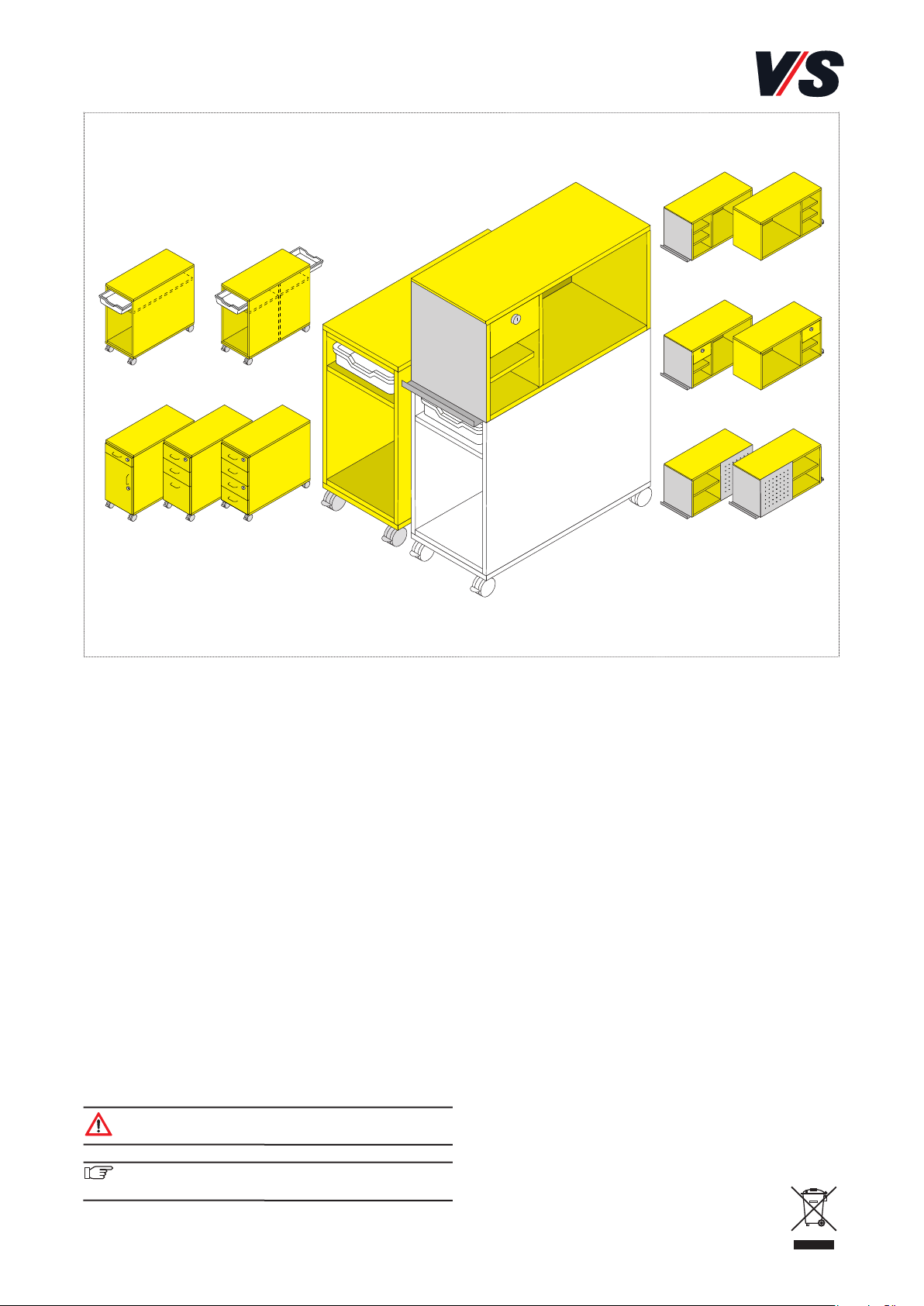
Bestimmung:
Mobile Schrankmodule für Schulen, Hochschulen, Seminare
und Weiterbildung. Für eine nicht bestimmungsgemäße
Benutzung wird keine Haftung übernommen. Für die Verwendung in geschlossenen Räumen.
Maximale Belastung je Schrank: 150 kg. Fachböden entsprechen der Belastungsgruppe L75, gemäß DIN 68874-1.
Maximale Belastung je Material-Box: 5kg.
Allgemeiner Hinweis zum Lesen und
Aufbewahren der Anleitung:
Lesen Sie diese Anleitung und vor allem die Sicherheitshinweise vor Benutzung der Produkte genau durch und beachten
Sie diese. Bewahren Sie die Anleitung zum späteren Nachlesen
sorgfältig auf und geben Sie diese an andere Benutzer weiter.
Allgemeiner Sicherheitshinweis:
In unseren Bedienanleitungen verwenden wir folgende
Symbole und Hinweise:
Achtung! Bei diesem Symbol handelt es sich um
einen sehr wichtigen Hinweis.
Wichtig! Bei diesem Symbol handelt es sich um
einen wichtigen Hinweis.
BEDIENUNGSANLEITUNG 70-372 V03 011019
LearnBox.
40050 40051
40055 40057
40056 40058
40052 40053
40054
40059 40060
2
1 2
(1)
(1)
(2)
(3)
3
4
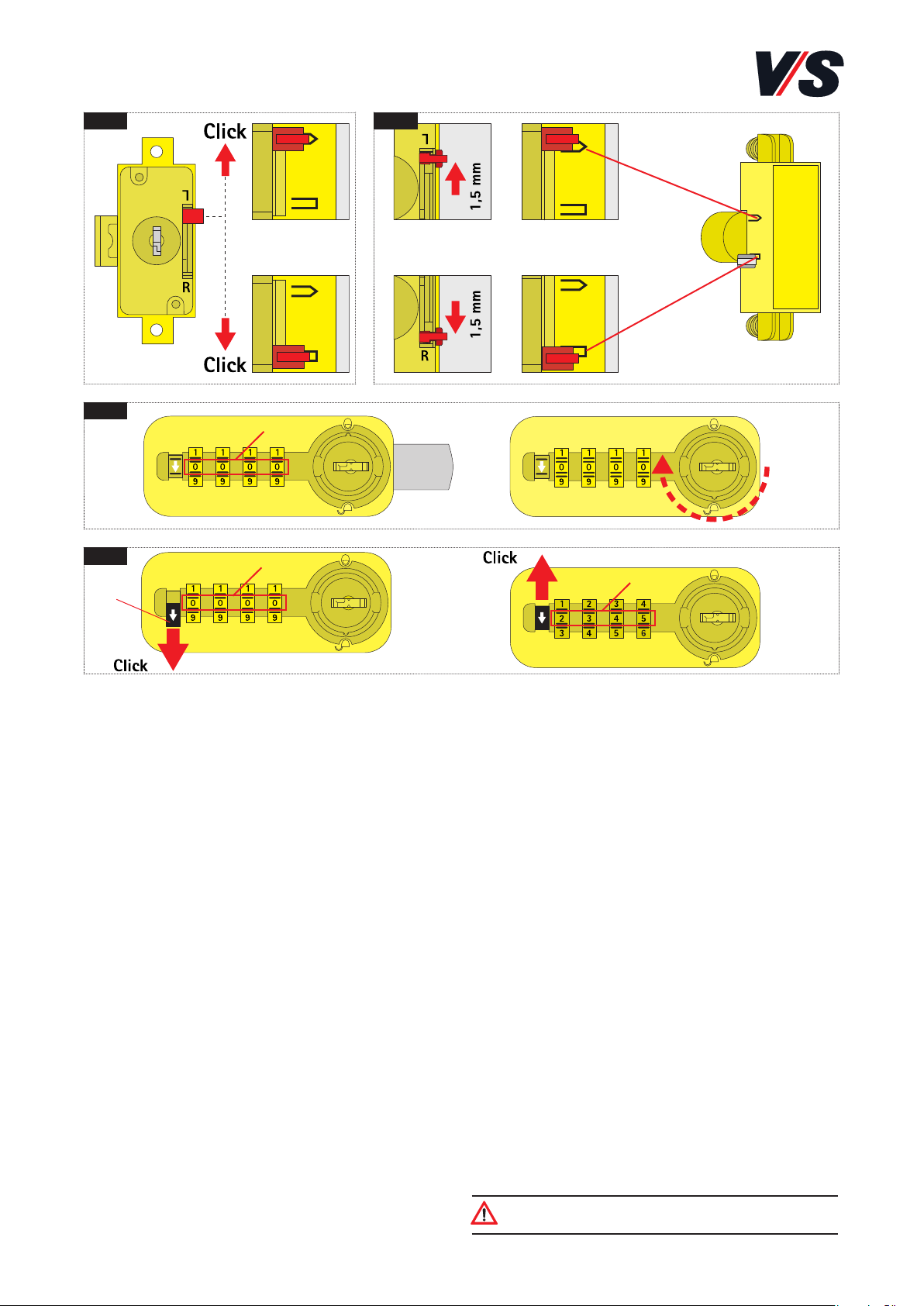
1 Schloss einstellen
Schließrichtung einstellen [Bild 1].
Schlüsselabzugssperre einstellen [Bild 2].
1.1 Zahlenschlösser
Die Zahlenschlösser werden schlüssellos mit vierstelligem
Code geöffnet.
Beim Zahlenschloss mit Fixcode wird der frei wählbare
Code vom Benutzer einmalig zum Öffnen eingestellt; diese
Einstellung bleibt erhalten. Bei einem Benutzerwechsel kann
der Fixcode neu programmiert werden.
Das Zahlenschloss mit Freecode erlaubt wechselnden Nutzern das sichere Verschließen des Schrankes. Für jedes
Schließen und Öffnen muss ein persönlicher Code neu eingegeben werden. Das automatische Verwischen des Codes
durch Nullrückstellung bietet erhöhte Sicherheit.
1.2 Zahlenschlösser mit Fixcode
Zahlenschloss öffnen [Bild 3]
Werkscode 0000 (1) oder den eingestellten Code wählen.
Schloss öffnen durch Rechtsdrehen. Die Zahlenräder stellen
sich auf 0000 zurück (Verwischtechnik).
Code ändern [Bild 4]
Werkscode 0000 (1) oder eingestellten Code wählen. Sperrriegel (2) bis zum Click nach unten drücken. Neuen Code
(3) eingeben. Sperrriegel bis zum Click nach oben schieben.
Der neue Code ist gespeichert.
Achtung! Der Kunde muss die Bedienungsanleitung
des Herstellers erhalten.
3
1
(1)
(2)
(3)
(4)
2
(5)
(6)
(7)
(8)
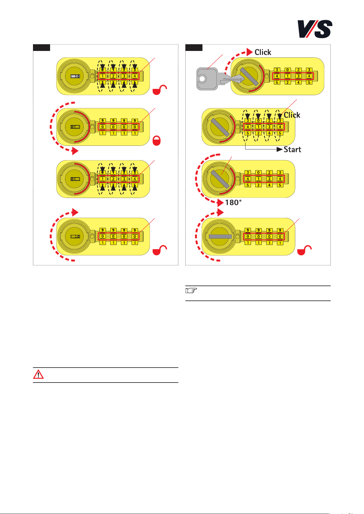
1.3 Zahlenschlösser mit Freecode
Zahlenschloss schließen und öffnen [Bild 1]
Durch Verwischtechnik stehen bei geöffnetem Schloss alle
Ziffern auf „0“.
Persönlichen Code (1) einstellen und Schloss durch Linksdrehung verschließen; dabei wird der Code automatisch verwischt (2).
Zum Öffnen den gewählten Code (3) eingeben und Schloss
durch Rechtsdrehung entsperren.
Code wird wiederum verwischt, alle Ziffern sind in Nullstellung (4). Das Schloss ist für die nächste Nutzung frei.
Achtung! Der Kunde muss die Bedienungsanleitung
des Herstellers erhalten.
Notöffnung mit Reset des Codes [Bild 2]
Wichtig! Notschlüssel erhalten Sie bei der Gebäude-
verwaltung.
Notschlüssel (5) ins Schloss stecken und bis zum „Click“
nach rechts drehen.
Vom Schloss ausgehend nacheinander die Zahlenräder (6)
bis zum „Click“ drehen.
Anschließend Notschlüssel um 180° nach links drehen (7),
dann Schloss durch Rechtsdrehung entsperren, Notschlüssel
abziehen.
Der programmierte Code ist gelöscht, Ziffern sind in Nullstellung (8). Das Schloss kann wieder im Normalbetrieb genutzt werden.
4
1
2
(3)
(1)
(2)
(2)
(5)
(4)
(6)
(7)
(6)
(3)
5
6
3
4
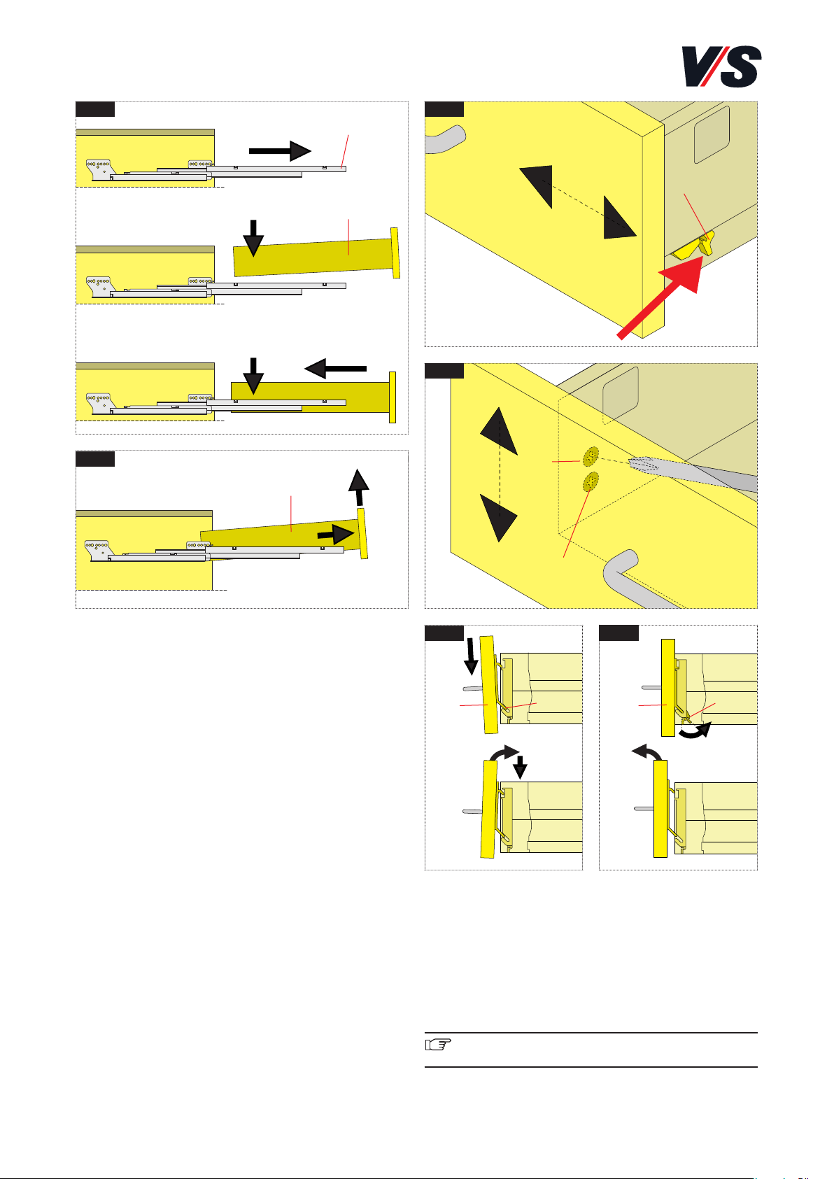
Montage der Schubkastenfront [Bild 5]
Front (6) mit Einhängehaken (7) in unteren, schrägen
Schlitz einführen (0-Positionierung durch Einhängehaken).
Front einschwenken und hinunterdrücken.
Demontage der Schubkastenfront [Bild 6]
Arretierhaken (3) von der Front (6) wegdrücken und Front
aushängen.
Wichtig! Falls erfoderlich separate Anleitung der Firma
Grass, Auszugs-System Nova Pro, konsultieren.
2 Schubkästen montieren und
einstellen
Schubkastenschränke werden in der Regel montiert geliefert.
Bei Bedarf sind die Schubkastenfronten seitlich und in der
Höhe verstellbar.
Montage der Schubkästen [Bild 1]
Korpusschiene (1) herausziehen, Schubkasten (2) leicht
schräg auf die Korpusschiene aufsetzen und einschieben bis
der Schubkasten einrastet.
Demontage der Schubkästen [Bild 2]
Schubkasten (2) komplett herausziehen und anheben.
Anheben = Ausschalten der Ausziehsicherung in Offenstellung.
Seitenverstellung der Schubkastenfronten [Bild 3]
Arretierhaken (3) links und rechts nach hinten drücken.
Front leicht anheben und über die Riffelung schieben
(Verstellweg ±1,5 mm). Arretierhaken loslassen.
Höhenverstellung der Schubkastenfronten [Bild 4]
Schraube (4) leicht lösen. Front über Exzenterschraube (5)
in die gewünschte Höhenposition bringen (Verstellweg
± 2 mm). Schraube (4) festziehen.

5
(1) (2) (3) (6)
(5)
(7)
(4)
1 2
3 Drehtüren einstellen
Achtung! Beim Öffnen und Schließen der Türen entsteht eine Klemmstelle zwischen Tür und Seite. Bei Einsatz in Bildungseinrichtungen muss die Nutzung unter
Aufsicht erfolgen: nach Nutzung sind die Türen zu
schließen.
[Bild 1]
Öffnungswinkel bis 110°.
Bei verdeckten Bändern: Schutzkappen abnehmen.
Je nach Ausrichtungsbedarf mit Schraubendreher justieren.
[Bild 1]
Einstellen über
(+3 / -2.0 mm) (1)
(±3 mm) (2)
(±2 mm) (3)
[Bild 2]
Öffnungswinkel bis 270°.
Bei sichtbaren Bändern: Schutzkappen abnehmen durch
Lösen der Schrauben (4). Dann je nach Ausrichtungsbedarf
mit Schraubendreher justieren.
[Bild 2]
Einstellen über
Exzenter - Auflagenverstellung (-2 mm) (5)
Exzenter - Höhenverstellung (±2 mm) (6)
Dritte Befestigungsschraube (7)
Wichtig! Nach erfolgter Justierung Schutzkappen
wieder aufsetzen.

6
1 2 5
3 4
4 Drehtüren Dämpfung
Bei verdeckten Bändern]
Dämpfung kann nach Bedarf an jedem Scharnier aktiviert
oder deaktiviert werden. Einfach mit dem Finger schieben.
Dämpfung aus
Schieber nach innen schieben [Bild 1]
Dämpfer klappt bei der nächsten Schließung nach innen
[Bild 2].
Dämpfung ein
Schieber nach vorn schieben [Bild 3].
Dämpfer klappt nach vorn [Bild 4].
Achtung! Bei kleinen Türen reicht die Dämpfung
eventuell nur an einem Scharnier.
Achtung!
Die Dämpfung ist im Auslieferungszustand aktiv!
Achtung! Beim Öffnen und Schließen der Türen entsteht eine Klemmstelle zwischen Tür und Seite. Bei Einsatz in Bildungseinrichtungen muss die Nutzung unter
Aufsicht erfolgen: nach Nutzung sind die Türen zu
schließen.
5 Gratnells Boxen:
Entnehmen: Boxen bis zum Anschlag nach vorne ziehen und
soweit anheben bis die Auszugssperre überwunden ist. Anschließend können Sie die Box entnehmen [Bild 5].
Einsetzen: Boxen von oben einsetzen, bis diese richtig in der
Führungsschiene positioniert sind, anschließend waagrecht
bis zum Anschlag einschieben.
Achtung! Entsprechende Schränke nur mit vollständig
eingeschobener Material-Box verfahren.

VS Vereinigte Spezialmöbelfabriken GmbH& Co. KG
Hochhäuser Straße 8 · 97941 Tauberbischofsheim · Tel.: 09341/880 · vs@vs-moebel.de
http://links.vs-service.com/downloads/70-372_V03_DEEN_LearnBox-112954.pdf
7
On the Web:
You can find these Instructions on the Web:
Standards:
Inspected in accordance with DIN EN 16121.
Scope of delivery:
The product is supplied partially/fully assembled.
Use:
Please take account of the notes on the following page.
Faults and service:
If any faults occur, please contact our Customer Service
kundenservice@vs-moebel.de
Maintenance and cleaning
On the Web: vs.de/kataloge/reinigung/
Product transfer and Disposal:
If the product is transferred to a new owner or user then it
must be accompanied by these Instructions.
The indicated electric and electronic components must not
be disposed of with the ordinary waste. They must
be removed from the furniture unit before the unit
is sent for disposal. They are to be disposed of at
authorized collection and return points.
Intended use:
Mobile cabinet modules for schools, colleges, seminars and
further education establishments. No liability will be assumed
for any use other than that intended. For use in closed
premises.
Maximum load per cabinet: 150 kg. Shelves correspond to
load group L75 as per DIN 68874-1.
Maximum load per materials box: 5 kg
General note on reading and retaining
these Instructions:
Read these Instructions and, in particular, the safety instructions carefully before using the products and adhere to
these. Keep these Instructions in a safe place for future
consultation and communicate them to other users.
General note on safety:
The following symbols and notes are used in our Instructions
for Use:
Caution!
This symbol indicates a very important note.
Important!
This symbol indicates an important note.
INSTRUCTIONS FOR USE 70-372 V03 011019
LearnBox.
40050 40051
40055 40057
40056 40058
40052 40053
40054
40059 40060

8
1 2
(1)
(1)
(2)
(3)
3
4
1 Adjusting the lock
Adjusting the locking direction [Figure 1].
Adjusting the key blocking mechanism [Figure 2].
1.1 Combination locks
Combination locks are opened without the need for a key
using a 4-digit code.
In the case of combination locks with a fixed code, the
freely definable code is entered by the user once to open
the unit and this setting is then retained. In the event of a
change of user, the fixed code can be reprogrammed.
Combination locks with free codes allow different users to
lock the cabinet securely. A personal code must be entered
again every time the cabinet is opened and closed. The automatic cancellation of the code by resetting the value to
zero increases security.
1.2 Combination locks with fixed code
Opening the combination lock [Figure 3]
Choose the factory-set code 0000 (1) or the defined code.
Open the lock by turning to the right. The digit wheels are
reset to 0000 (to cancel the previous code).
Changing the code [Figure 4]
Choose the factory-set code 0000 (1) or the defined code.
Press the locking bar (2) down until you hear a click. Enter
the new code (3). Press the locking bar up until you hear a
click. The new code is stored.
Caution! The customer must be given the
manufacturer's operating instructions.

9
1
(1)
(2)
(3)
(4)
2
(5)
(6)
(7)
(8)
1.3 Combination locks with free code
Closing and opening the combination lock [Figure 1]
Thanks to the code clearance technology, all the digits
display "0" when the cabinet is open.
Set your personal code (1) and close the lock by turning it
to the left. This automatically clears the code (2).
To open the cabinet, enter your defined code (3) and unlock
by turning the lock to the right.
The code is cleared again and all the digits display zero (4).
The lock is now ready to be used again.
Caution! The customer must be given the
manufacturer's operating instructions.
Emergency opening with code reset [Figure 2]
Important! You can obtain the emergency key from
the building's administrative office.
Insert the emergency key (5) in the lock and turn it to the
right until you hear a click.
Starting from the lock mechanism end, turn the digit wheels
(6) until you hear a click.
Then turn the emergency key 180° to the left (7) and unlock
by turning the lock to the right. Remove the emergency key.
The programmed code is deleted and the digits are set to
zero (8). The lock can now be used again normally.

10
1
2
(3)
(1)
(2)
(2)
(5)
(4)
(6)
(7)
(6)
(3)
5
6
3
4
Assembling the drawer front [Figure 5]
Insert the front (6) with the mounting hook (7) in the lower,
oblique slit (initial positioning ensured by mounting hook).
Tilt in the front and press down.
Disassembling the drawer front [Figure 6]
Press the catch (3) away from the (6) and unhook the front.
Important! If necessary, consult the separate instructions
issued by Grass for the Nova Pro drawer system.
2 Assembling and adjusting
the drawers
Drawer cabinets are usually supplied assembled. The lateral
alignment and height of the fronts of the drawer cabinets
can be adjusted if required.
Assembling the drawers [Figure 1]
Pull out the body rail (1), position the drawer (2) on the body
rail at a slight angle and push in until the drawer engages.
Dissembling the drawers [Figure 2]
Pull the drawer (2) out completely and lift.
Lifting = deactivating the pull-out protection in the open
position.
Lateral adjustment of the drawer fronts [Figure 3]
Press the left and right catches (3) backwards. Lift the front
slightly and push over the corrugated section (adjustment
path ± 1.5 mm). Release the catch.
Height adjustment of the drawer fronts [Figure 4]
Loosen screw (4) slightly. Use the eccentric screw (5) to
adjust the front to the required vertical position (adjustment
path. ± 2 mm). Tighten screw (4).

11
(1) (2) (3) (6)
(5)
(7)
(4)
1 2
3 Adjusting the swing doors
Caution! When the doors are opened and closed, it is
possible for items or fingers to become trapped between the door and the side of the unit. If the units are
used in teaching establishments then their use must be
supervised and the doors must be closed after use.
[Figure 1]
Opening angle up to 110°.
In the case of concealed hinges: Remove the protective caps.
Adjust as required using a screwdriver.
[Figure 1]
Adjust to
(+3 / -2.0 mm) (1)
(±3 mm) (2)
(±2 mm) (3)
[Figure 2]
Opening angle up to 270°.
In the case of visible hinges: Release the screws (4) and
remove the protective caps. Then adjust as required using
a screwdriver.
[Figure 2]
Adjust to
Eccentric screw - positional adjustment (-2 mm) (5)
Eccentric screw - height adjustment (±2 mm) (6)
Third fixing screw (7)
Important! When adjustment is complete, replace the
protective caps.

12
1 2 5
3 4
4 Damping of swing doors
In the case of concealed hinges
Damping can be activated or deactivated at each hinge as
required. Just push using the finger.
Damping off
Press slider inwards [Figure 1].
Damper folds in the next time the door is closed [Figure 2].
Damping on
Press slider forwards [Figure 3].
Damper folds forwards [Figure 4].
Caution! In the case of small doors, damping at just
one hinge may be sufficient.
Caution!
Damping is active when the unit is delivered!
Caution! When the doors are opened and closed, it is
possible for items or fingers to become trapped between the door and the side of the unit. If the units are
used in teaching establishments then their use must be
supervised and the doors must be closed after use.
5 Gratnells trays:
Removing: Pull the boxes forwards as far as the stop and
then lift them until they pass above the pull-out lock. You
can then remove the box [Figure 5].
Inserting: Insert the boxes from above until they are correctly positioned in the guide rail. Then push them in horizontally as far as the stop.
Caution! If cabinets are equipped with materials boxes
then these boxes must be fully inserted before the
units are moved.
 Loading...