

VS Vereinigte Spezialmöbelfabriken GmbH&Co.KG
Hochhäuser Straße 8 · 97941 Tauberbischofsheim · Tel.: 09341/880 · vs@vs-moebel.de
http://links.vs-service.com/downloads/70-357_V08_DEEN_S910_Hoehenverstellung-142159.pdf
BEDIENUNGSANLEITUNG: 70-357 V08 031119
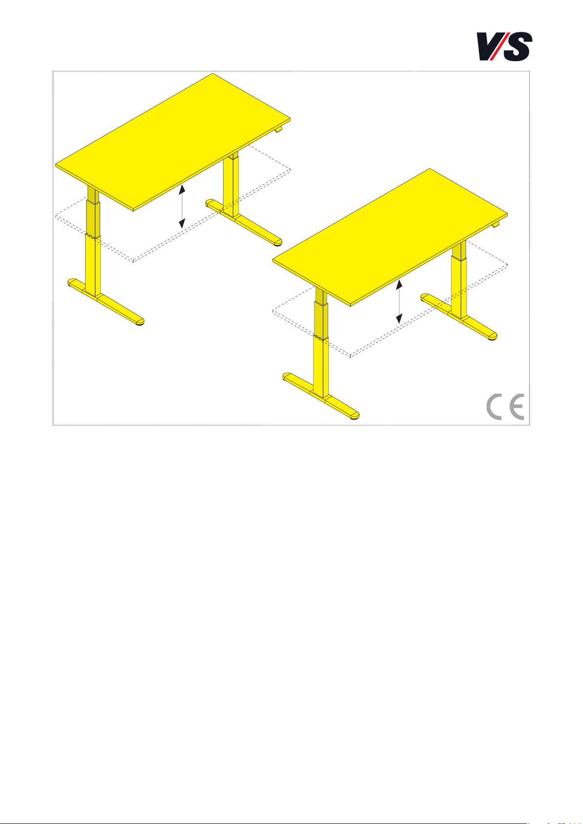
Serie 910
Höhenverstellbarer
Sitz-/ Steharbeitsplatz.
C-Fuß, T-Fuß.
Bitte sorgfältig aufbewahren!
OPERATING INSTRUCTIONS: 70-357 V08 031119
Serie 910
Height-adjustable
seated/standing workplace.
C-foot, T-foot.
Please keep these Instructions
carefully!

2
Inhalt.
Allgemeiner Sicherheitshinweis 3
Sicherheitshinweise 3
1. Allgemeine Hinweise 6
1.1 Stellenwert der Bedienungsanleitung 6
1.2 Bestimmungsgemäße Verwendung (Einsatzbereich) 6
1.3 Sachwidrige Verwendung 7
1.4 Lieferumfang, Montage, Transport, Lagerung 7
1.5 Weitergabe/Entsorgung 8
2. Sicherheitshinweise 9
3. Auahrschutz 11
3.1 Info zum Auahrschutz 11
3.2 Nutzungshinweise 11
4. Bedienung Tischhandschalter 12
4.1 Höhenverstellung 12
4.3 Speicherpositionen 13
4.4 Tastensperre/Sicherung in privaten Räumen 14
4.5 Bluetooth® Verbindung 15
4.6 Erinnerung / Einstellen des Erinnerungsintervalls 15
4.7 Container- und Regal-Stopp 17
5. Fehlerbehebung 18
5.1 Der Tisch verfährt nicht 18
5.2 Resetfahrt (Initialisierung) 19
5.3 Fehlercodes 19
5.4 Fehlerbehebung Kunde / VS Kundendienst 19
6. Tische mit Kurbelhöhenverstellung 21
7. Tischmanagement 22
7.1 Tischplatte verschieben/abnehmen 22
7.2 Kabelwannen 23
7.3 Kabelketten 24
7.4 CPU-Halter, ThinClient-Halter, Druckerboard 25
7.5 Tischabstandshalter 26
7.6 Elektrifizierungsklappe/E-Box 26
8. Doppeltische Twin 27
9. Technische Daten 28
10. Hinweise zur Ergonomie 29
11 . EU-Konformitätserklärung 31
3
Allgemeiner Sicherheitshinweis:
In unseren Anleitungen verwenden wir folgende Symbole und Hinweise:
Wichtig! Bei diesem Symbol handelt es sich um einen wichtigen
Montagehinweis.
Achtung! Bei diesem Symbol handelt es sich um einen sehr wichtigen
Hinweis.
Sicherheitshinweise:
Achtung! Lesen Sie diese Anleitung vor Inbetriebnahme des Systems
bitte genau durch und bewahren Sie diese zum späteren Nachschlagen
sorgfältig auf. Alternative Bereitstellung per Download:
(siehe Kopfleiste Titel).
Achtung! Der Sitz-/Steharbeitsplatz darf in privaten Räumen nur
mit einer speziellen Sicherung (siehe Kapitel 4.3) verwendet werden.
Diese Sicherung zum Schutz vor unberechtigter Nutzung ist zwingend
zu aktivieren!
Achtung!
Kinder dürfen nicht mit dem Gerät spielen.
Achtung! Nagetiere sollten von elektrischen Betriebsmitteln und
deren Zuleitungen ferngehalten werden. Durch beschädigte Leitungen
kann es zur Gefahr für Mensch und Tier kommen.
Achtung! Die Sicherheitshinweise sind unbedingt zu beachten! Wird
das System unsachgemäß betrieben, können Gefahren für Personen
und Sachgegenstände entstehen!
Wichtig! Büromöbel mit elektrischer Installation sind entsprechend
den Unfallverhütungsvorschriften und den allgemein anerkannten
Regeln der Technik in den dort vorgegebenen Zeitabständen zu überprüfen.
4
Achtung! Beim Fahren des Antriebs ist darauf zu achten, dass keine
Gegenstände (z.B. Möbel) oder Körperteile eingeklemmt werden!
Bei jeder Bedienung hat der Benutzer sich grundsätzlich davon zu
überzeugen, dass sich keine weiteren Personen am Tisch aufhalten
und der Verfahrweg frei von Hindernissen ist. Zu nebenstehenden
Gegenständen ist ein Mindestabstand von 25 mm einzuhalten, um
Quetsch- und Scherstellen zu vermeiden!
Achtung! Bevor Sie das System in Betrieb nehmen, überprüfen Sie
ob die Betriebsspannung des Systems der lokalen Stromversorgung
entspricht. Das System ist in Betrieb, sobald der Netzanschluss
angeschlossen ist.
Achtung! Der Auahrschutz ist kein Einklemm- und kein Personenschutz! Aus physikalischen Gründen können “weiche” Hindernisse
nur schlecht oder gar nicht erkannt und ausgewertet werden! Im
Falle eines Auahrens auf ein Hindernis ist es nicht auszuschließen,
dass das Hindernis Beschädigungen erhalten kann, da der Tisch mit
Nenngeschwindigkeit auährt!
Achtung! Bei Störungen ist ein manueller Reset (Initialisierung)
durchzuführen.
Achtung! Wenn der Handschalter losgelassen wird, bevor der Vorgang
komplett abgeschlossen ist, wird die Initialisierung unterbrochen und
muss neu begonnen werden. Bei einer abgebrochenen Initialisierung
ist keine Aufwärtsfahrt des Systems möglich.
5
Achtung! Wenn der Handschalter gesperrt ist, leuchtet im Display
ein Schloss. Das Licht wird für eine Sekunde rot.
Achtung! Im Falle eines Auahrens auf ein Hindernis ist es nicht
auszuschließen, dass das Hindernis beschädigt wird, da der Tisch
mit Nenngeschwindigkeit auährt!
Achtung! Innerhalb der Garantiezeit ist der Austausch der Antriebstechnik nur durch den VS-Kundendienst (VS-KD) zulässig.
Wichtig! Für weitere Fragen wenden Sie sich an ihren zuständigen
VS-Fachberater bzw. an die entsprechende VS-Niederlassung.
Achtung! Nach dem Verstellen der Tischhöhe muss die Handkurbel
wieder in der Parkposition arretiert werden.
Achtung! Beim Verschieben der Tischplatte die Elektrifizierungsklappe
immer geönet halten.
Achtung! Vor dem Verschieben/Abnehmen muss die Tischplatte
abgeräumt werden.
Achtung!
Zugentlastung der Kabelwannen benutzen.
Achtung! Quetschgefahr bei höhenverstellbaren Tischen. Tischabstandshalter gewährleisten den erforderlichen Sicherheitsabstand.
Achtung! Beim Fahren des Antriebs ist darauf zu achten, dass keine
Gegenstände oder Körperteile eingeklemmt werden!

6
1. Allgemeine Hinweise:
Achtung! Lesen Sie diese Anleitung vor Inbetriebnahme des Systems
bitte genau durch und bewahren Sie diese zum späteren Nachschlagen
sorgfältig auf. Alternative Bereitstellung per Download:
(siehe Kopfleiste Titel).
1.1 Stellenwert der Bedienungsanleitung:
- Grundvoraussetzung für den sicherheitsgerechten Umgang und den
störungsfreien Betrieb dieses Sitz-/Steharbeitsplatzes ist die Kenntnis
der grundlegenden Sicherheitshinweise und der Sicherheitsvorschriften.
- Diese Bedienungsanleitung enthält die wichtigsten Hinweise, um den
Sitz-/Steharbeitsplatz sicherheitsgerecht zu betreiben.
- Diese Bedienungsanleitung, insbesondere die Sicherheitshinweise,
sind von allen Personen zu beachten, die an dem Sitz-/Steharbeitsplatz arbeiten (z.B. Wartungspersonal, Bediener, technischer Leiter,
Elektriker).
- Darüber hinaus sind die für den Einsatzort geltenden Regeln und
Vorschriften zur Unfallverhütung zu beachten.
- Diese Anleitung entspricht dem aktuellen Stand zum Zeitpunkt der
Drucklegung. Produktänderungen, die dem Fortschritt dienen, in
Technik oder Design, bleiben vorbehalten.
1.2 Bestimmungsgemäße Verwendung (Einsatzbereich):
Der vorliegende Sitz-/Steharbeitsplatz ist ein Büroarbeitstisch bzw. Bildschirmarbeitstisch, der ausschließlich für sitzende und stehende Tätigkeiten
im Bürobereich konzipiert wurde und somit auch nur für diesen Verwendungszweck bestimmt ist. Eine andere oder darüber hinausgehende
Benutzung (z. B. in Werkstätten, Lagerbereichen, Explosionsbereichen,
Feuchträumen) gilt als nicht bestimmungsgemäß. Für hieraus entstehende
Schäden haftet die Firma VS Vereinigte Spezialmöbelfabriken GmbH&Co.KG
nicht.
Achtung! Der Sitz-/Steharbeitsplatz darf in privaten Räumen nur
mit einer speziellen Sicherung (siehe Kapitel 4.3) verwendet werden.
Diese Sicherung zum Schutz vor unberechtigter Nutzung ist zwingend
zu aktivieren!
7
1.3 Sachwidrige Verwendung:
- Dieses Gerät kann von Kindern ab 8 Jahren und darüber sowie von
Personen mit verringerten physischen, sensorischen oder mentalen
Fähigkeiten oder Mangel an Erfahrung und Wissen benutzt werden,
wenn sie beaufsichtigt oder bezüglich des sicheren Gebrauchs des
Gerätes unterwiesen wurden und die daraus resultierenden Gefahren
verstehen. Die Reinigung darf nicht von Kindern ohne Beaufsichtigung
durchgeführt werden.
- Verwenden Sie den Sitz-/Steharbeitsplatz niemals zum Heben von
Personen oder Lasten.
- Belasten Sie den Sitz-/Steharbeitsplatz nur bis zur maximalen vollflächigen Last (siehe Kapitel 8 Technische Daten).
Achtung!
Kinder dürfen nicht mit dem Gerät spielen.
Achtung! Nagetiere sollten von elektrischen Betriebsmitteln und
deren Zuleitungen ferngehalten werden. Durch beschädigte Leitungen
kann es zur Gefahr für Mensch und Tier kommen.
1.4 Lieferumfang, Montage, Transport, Lagerung:
- Der Sitz-/Steharbeitsplatz wird von VS Vereinigte Spezialmöbelfabriken
GmbH&Co.KG komplett montiert geliefert.
- Während der Garantiezeit sind Reparaturen nur von Mitarbeitern der
VS Vereinigte Spezialmöbelfabriken GmbH&Co.KG durchzuführen.
- Die Montage von nachträglich geliefertem Zubehör bzw. dadurch
erforderliche Umbaumaßnahmen sind nur nach genauer Kenntnis der
Montageanleitung vorzunehmen. Es darf nur originales VS-Zubehör
verwendet werden.
- Wenn Sie den Sitz-/Steharbeitsplatz umsetzen müssen, achten Sie
darauf, dass der Netzstecker gezogen ist und sich keine Gegenstände
auf dem Tisch befinden.
- Tragen Sie den Sitz-/Steharbeitsplatz nur am Gestell bzw. benutzen
Sie einen Wagen (Möbelroller).
8
- Bewegen Sie den Sitz-/Steharbeitsplatz nur mit zwei Personen und
im eingefahrenen Zustand. Ziehen oder kippen Sie den Sitz-/Steharbeitsplatz auf keinen Fall.
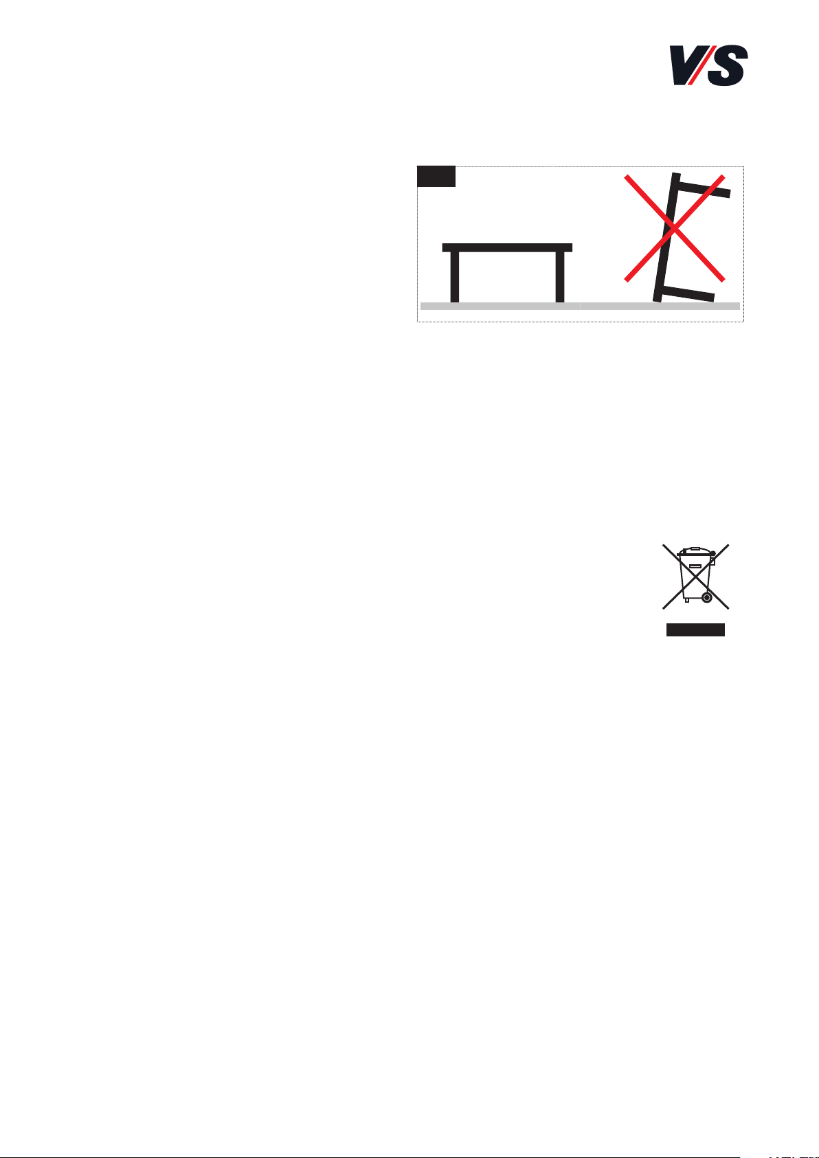
- Bei einer Lagerung der Tische
darf maximal ein Tisch auf einen
anderen gestapelt werden.
Vermeiden Sie hierbei Beschädigungen. Der Tisch muss sich
beim Stapeln in der untersten
Position befinden. Tische nur in der Funktions-Stellung lagern [Bild 1].
1.5 Weitergabe und Entsorgung:
- Bei der Weitergabe des Produkts an Dritte ist auch diese Bedienungsanleitung zu übergeben. Für eine umweltfreundliche Entsorgung
informieren Sie sich bitte bei Ihrer zuständigen Kommune.
- Die gekennzeichneten E-Komponenten dürfen nicht über den
Hausmüll entsorgt werden.
Sie müssen von dem Möbel getrennt werden, bevor das
Möbel der Entsorgung zugeführt wird.
Die Entsorgung erfolgt an zugelassenen Sammel- und
Rücknahmestellen.
1
9
2. Sicherheitshinweise.
Achtung! Die Sicherheitshinweise sind unbedingt zu beachten! Wird
das System unsachgemäß betrieben, können Gefahren für Personen
und Sachgegenstände entstehen!
- Önen Sie nie das Gehäuse der Steuerung oder des Netzteils! Durch
unbefugtes Önen des Gehäuses und unsachgemäße Reparaturen
können Gefahren für die Benutzer entstehen und der Garantieanspruch
erlischt. Das Önen oder Reparieren der elektrischen Einrichtungen
darf nur vom VS-Kundendienst durchgeführt werden!
- Bei Funktionsstörungen wie zum Beispiel Rauch- oder Geruchsentwicklung oder ungewöhnlichen Geräuschen oder bei sichtbaren
äußerlichen Beschädigungen darf das Gerät nicht weiter betrieben
werden. Ziehen Sie den Netzstecker und informieren Sie den
VS-Kundendienst (Tel.: 09341/880)!
- Die Netzanschlussleitung zur Netzsteckdose muss nahe des Tisches
angebracht und leicht zugänglich sein.
- Elektrische Zuleitungen dürfen keiner Quetschgefahr, Biege- und
Zugbeanspruchung ausgesetzt werden! Achten Sie außerdem darauf,
dass die Kabel aufgrund der Hubbewegung ausreichend lang sind.
- Beachten Sie bei der Elektrifizierung der Büromöbel die geltenden
Leitlinien: Elektrifizierung nur durch Fachpersonal!
Wichtig! Büromöbel mit elektrischer Installation sind entsprechend
den Unfallverhütungsvorschriften und den allgemein anerkannten
Regeln der Technik in den dort vorgegebenen Zeitabständen zu überprüfen.
- Schützen Sie die elektrischen Bauteile vor Feuchtigkeit, Tropf- und
Spritzwasser.
- Die Steuerung und der Tischhandschalter dürfen nur mit einem
trockenen oder leicht befeuchteten Tuch gereinigt werden.
10
Achtung! Beim Fahren des Antriebs ist darauf zu achten, dass keine
Gegenstände (z.B. Möbel) oder Körperteile eingeklemmt werden!
Bei jeder Bedienung hat der Benutzer sich grundsätzlich davon zu
überzeugen, dass sich keine weiteren Personen am Tisch aufhalten
und der Verfahrweg frei von Hindernissen ist. Zu nebenstehenden
Gegenständen ist ein Mindestabstand von 25mm einzuhalten, um
Quetsch- und Scherstellen zu vermeiden!
- Der Tisch darf nur mit der mitgelieferten/installierten Steuerung,
bzw. Netzteil betrieben werden!
- Zum Schutz gegen Überspannungen, wie sie bei Gewittern auftreten
können, empfiehlt sich die Installation eines Überspannungsschutzes.
Lassen Sie sich von Ihrem Elektroinstallateur beraten.
- Beachten Sie die Angaben zu Einschaltdauer, Temperatur etc.
(siehe Kapitel 8).
Achtung! Bevor Sie das System in Betrieb nehmen, überprüfen Sie
ob die Betriebsspannung des Systems der lokalen Stromversorgung
entspricht. Das System ist in Betrieb, sobald der Netzanschluss
angeschlossen ist.
- Reinigungen dürfen nicht von Kindern ohne Beaufsichtigung durchgeführt werden.
- Wenn die Netzanschlussleitung dieses Gerätes beschädigt wird, muss
sie durch den Hersteller oder seinen Kundendienst oder eine ähnlich
qualifizierte Person ersetzt werden, um Gefährdungen zu vermeiden.
Garantie kann nur für bestimmungsgemäßen Gebrauch gewährt werden.
Das Produkt ist wartungsfrei.

11
3. Auffahrschutz
Achtung! Der Auahrschutz ist kein Einklemm- und kein Personenschutz! Aus physikalischen Gründen können “weiche” Hindernisse
nur schlecht oder gar nicht erkannt und ausgewertet werden! Im
Falle eines Auahrens auf ein Hindernis ist es nicht auszuschließen,
dass das Hindernis Beschädigungen erhalten kann, da der Tisch mit
Nenngeschwindigkeit auährt!
3.1 Info zum Auffahrschutz
- Wenn sich der Tisch in der Auf- bzw. in der Abwärtsfahrt befindet
und auf ein Hindernis trit und erkennt, verhindert der Auahrschutz eine Schrägstellung bzw. die Weiterfahrt des Tisches. Wird ein
Hindernis erkannt, so wird die Fahrt des Tisches gestoppt und automatisch eine Umkehrfahrt eingeleitet (Dierenz der Umkehrfahrt:
ca. 5 cm).
3.2 Nutzungshinweise
- Anfahrt/Beschleunigungsphase: Nach dem Beginn einer Fahrt können
Hindernisse erst nach einer zurückgelegten Strecke von ca. 2 cm, nach
Erreichen der Nenngeschwindigkeit, erkannt werden.
- Belastung: Mit einem unbelasteten Tisch können Hindernisse nur
schlecht bzw. gar nicht erkannt werden.
- Weiche Hindernisse: Unter weichen Hindernissen verstehen sich alle
Arten von Hindernissen, die bei einem Auahren zunächst nachgeben,
wie dies z. B. bei menschlichen Körperteilen, gepolsterten Stühlen
usw. der Fall ist. Weiche Hindernisse können nur schlecht bzw. gar
nicht erkannt werden.
- Einschaltdauerbegrenzung: Die Elektronik überwacht, wie lange die
Antriebe verfahren werden. Wird die maximal zulässige Zeit überschritten, so lässt die Elektronik ein weiteres Verfahren der Antriebe
nicht zu (siehe Kapitel 8).
12
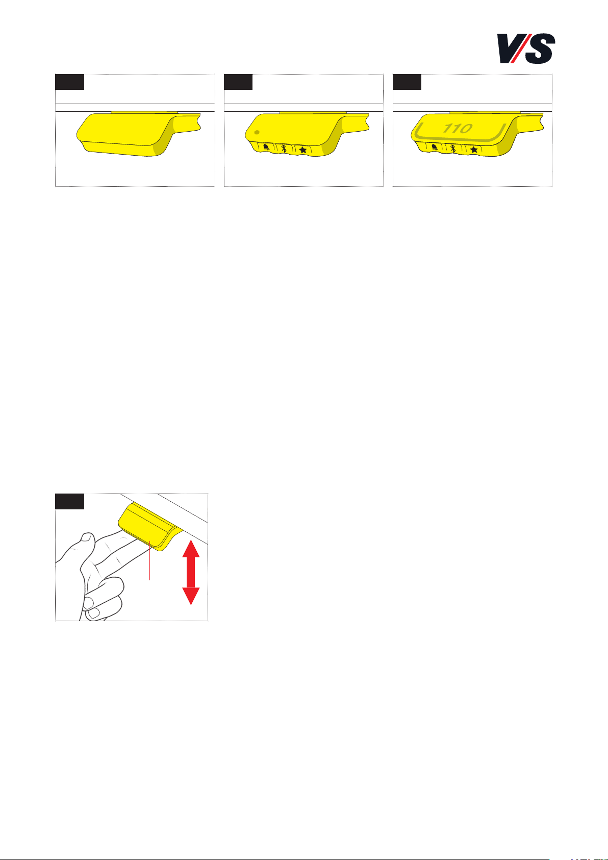
Handschalter
Standard [Bild 1]
• Auf/Ab-Funktion
Handschalter
Memory [Bild 2]
• Auf/Ab-Funktion
• 2 Speicherpositionen
• Erinnerungsfunktion
über LED
• Bluetooth®
Handschalter
Memory-Display [Bild 3]
• Auf/Ab-Funktion
• 4 Speicherpositionen
• Erinnerungsfunktion
über Lichtleiste
• Bluetooth®
• Display
4. Bedienung Tischhandschalter.
4.1 Höhenverstellung
Zur Höhenverstellung der Tische kommen 3 verschiedene Handschalter
mit unterschiedlichen Funktionen zum Einsatz:
Höhenverstellung
Kippen Sie den Handschalter (1) nach oben, um
den Tisch nach oben zu fahren. Kippen Sie den
Handschalter (1) nach unten, um den Tisch nach
unten zu fahren. Die Antriebe fahren, so lange
Sie den Handschalter (1) gekippt halten. Beim
Handschalter Memory-Display wird die aktuelle
Höhe des Tisches im Display in cm angezeigt.
- Softstart/Softstopp: Die Antriebe werden für kurze Zeit nach dem
Start bzw. vor dem Stopp mit verminderter Leistung betrieben.
- Sicherheitsbereich: Aus Sicherheitsgründen ist die Steuerung des
Tisches werksseitig mit zwei unteren Endlagen (siehe Kapitel 8)
ausgerüstet (Sicherheitsbereich). Bei der gebräuchlichen Verfahrweise
wird eine erste untere Endlage vor der untersten Position angefahren.
Nur durch erneute Betätigung des Handschalters kann der Tisch bei
verminderter Geschwindigkeit in die unterste Position verfahren
werden.
1 2 3
4
(1)
13
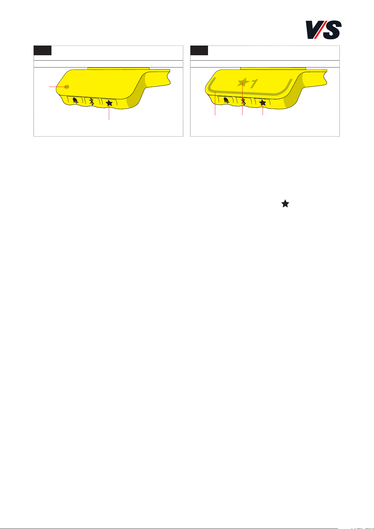
4.2 Speicherpositionen
- Handschalter Memory und Handschalter Memory-Display:
Speichern der Positionen 1 und 2
Die Handschalter [Bild 1] haben auf der rechten Seite eine
„Speichern“-Taste (1) – symbolisiert durch einen Stern .
- Fahren Sie den Schreibtisch auf eine bevorzugte Position und drücken
Sie die Stern-Taste (1) für 2 Sekunden. Beim Handschalter Memory
blinkt die LED (2), beim Handschalter Memory-Display [Bild 2] die
Lichtleiste (3) zweimal weiß, um anzuzeigen, dass der Speichervorgang läuft.
- Nur Handschalter Memory-Display [Bild 2]: Das Display zeigt die
gespeicherte Position mit einem Stern und der Positionsnummer an.
Die Zahl neben dem Stern entspricht der Reihenfolge, in der die
Positionen gespeichert werden. Erste Position gespeichert: Ein Stern
mit einer „1“ daneben (4). So werden die Speicherpositionen „1“ und
„2“ gespeichert.
- Wenn der Anwender den Schreibtisch zu einer anderen Position fährt
und diese speichert, überschreibt er die Speicherposition, die der
aktuellen Position am nächsten kommt.
- Zusätzliche Funktion bei Handschalter Memory-Display [Bild 2]:
Speichern der Positionen 3 und 4
Der Handschalter verfügt über 4 Speicherpositionen. Wenn Sie die
Stern-Taste (1) kurz drücken, zeigt das Display eine der 4 Speicherpositionen an. Sie können durch mehrmaliges kurzes Drücken der
Stern-Taste (1) zwischen diesen 4 Speicherpositionen umschalten und
auswählen, unter welcher Nummer die aktuelle Position gespeichert
werden soll. Beispielsweise möchte der Anwender die aktuelle Position
als Speicherposition 3 speichern: Drücken Sie die Stern-Taste mehrmals
1 2
(1) (1)(4)
(2)
(3)
14
bis im Display der „Stern“ mit der „3“ daneben erscheint. Führen Sie
nun denselben Speichervorgang wie oben beschrieben durch: Drücken
Sie den Stern für 2 Sekunden und die Position wird gespeichert.
- Anfahren von Speicherpositionen
Nach dem Speichern der Speicherpositionen können diese einfach
durch Drücken und Halten des Handschalters angefahren werden. Ist
eine gespeicherte Position erreicht, stoppt der Tisch automatisch.
Auf diese Weise kann der Anwender zwischen Stehen und Sitzen
wechseln, ohne eigens auf den Handschalter zu schauen.
- Wenn der Tisch bei einer gespeicherten Position stoppt, kann der
Anwender den Handschalter für eine Sekunde drücken und der Tisch
fährt an der gespeicherten Position vorbei in die Richtung, in die
gedrückt wird. Alternativ dazu kann der Anwender den Handschalter
auch loslassen und dann erneut drücken, um an der Speicherposition
vorbeizufahren.
- Gespeicherte Positionen löschen
Drücken Sie die Stern-Taste für 8 Sekunden, um alle gespeicherten
Positionen zu löschen. Die LED bzw. das Lichtband blinkt rot, wenn
der Vorgang abgeschlossen ist.
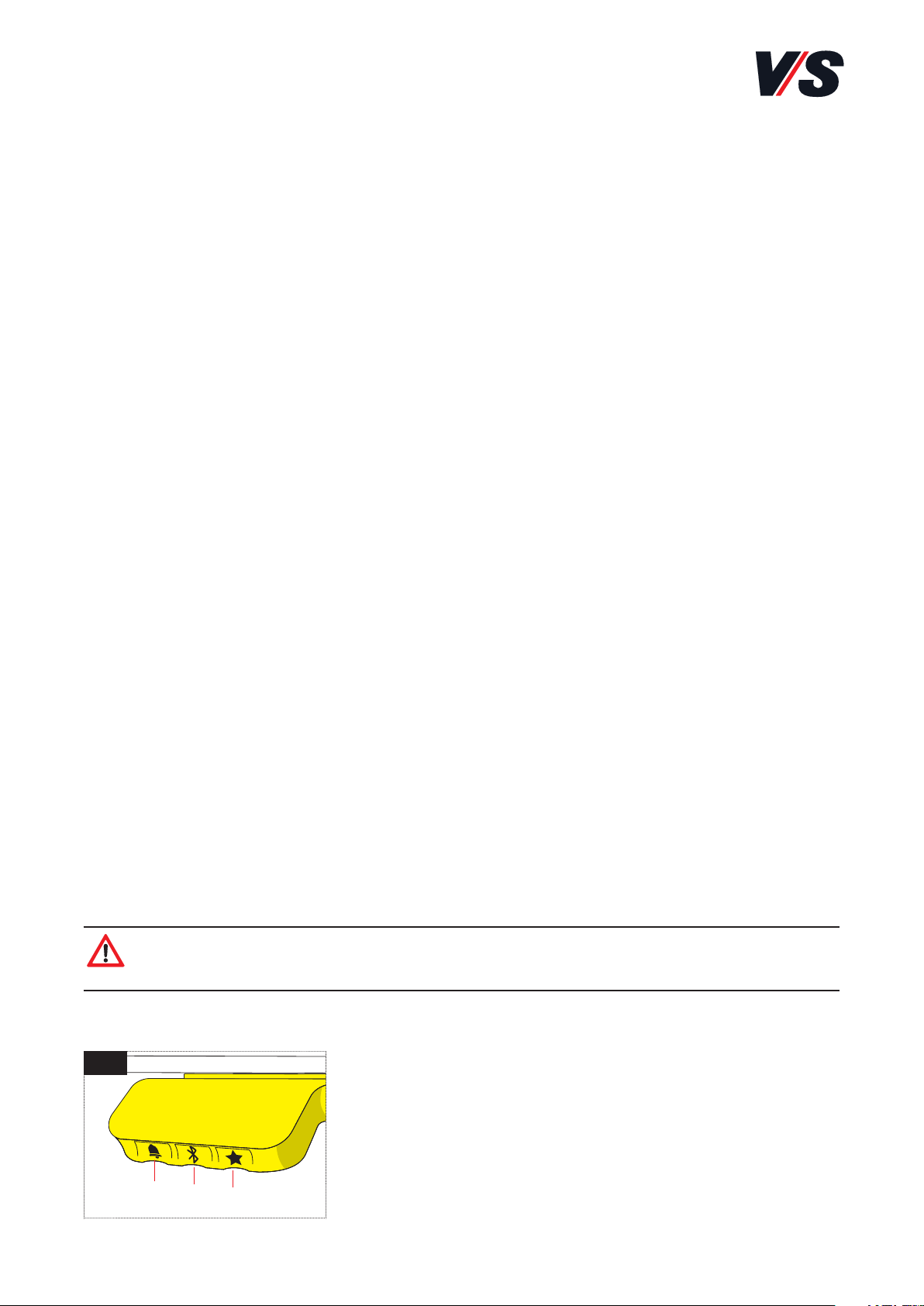
4.3 Tastensperre/Sicherung in privaten Räumen
Der Handschalter (VS-Teil-Nr. 88-668) für die Verwendung des Tisches im
privaten Bereich muss über eine Sperrfunktion gesichert sein. Ist diese
Funktion nicht vorhanden, wenden Sie sich bitte an den VS-Kundendienst (Tel. 09341/880)!
Achtung! Wenn der Handschalter gesperrt ist, leuchtet im Display
ein Schloss. Das Licht wird für eine Sekunde rot.
Um das Bedienelement zu entsperren [Bild 1], drücken Sie die Tasten
Glocke (1) - Bluetooth (2) -Stern (3) direkt
hintereinander (max. 1 Sekunde Abstand). Wenn
der Handschalter entsperrt ist, wird die Höhe im
Display angezeigt. Der Handschalter ist nun
aktiviert. Durch Drücken des Handschalters
können Sie den Tisch wie gewünscht verstellen.
1
(1)
(2)
(3)
15
Danach bleibt der Handschalter für weitere 5 Sekunden aktiviert. Wird in
dieser Zeit nicht erneut eine Taste gedrückt, ist der handschalter wieder
gesperrt.
4.4 Bluetooth® Verbindung
Handschalter Memory und Memory-Display [Bild 1-2]:
Laden Sie die für Ihr Gerät geeignete Desk Control App im App Store
bzw. in Google Play herunter und koppeln Sie die App mit Ihrem
Gerät: Drücken Sie die Bluetooth® Taste (1) in der Mitte für 2 Sekunden,
um den Kopplungsmodus zu aktivieren.
Ein blaues Blinklicht in der LED (3) bzw. in der Lichtleiste (4) zeigt
an, dass der Kopplungsmodus aktiv ist.
Beim Handschalter Memory-Display informiert die Anzeige über die
Bluetooth-ID des Schreibtisches, die sich aus „DESK (TISCH)“ gefolgt
von einer vierstelligen Nummer zusammensetzt– suchen Sie diese ID
in der Liste „Tische in der Nähe“.
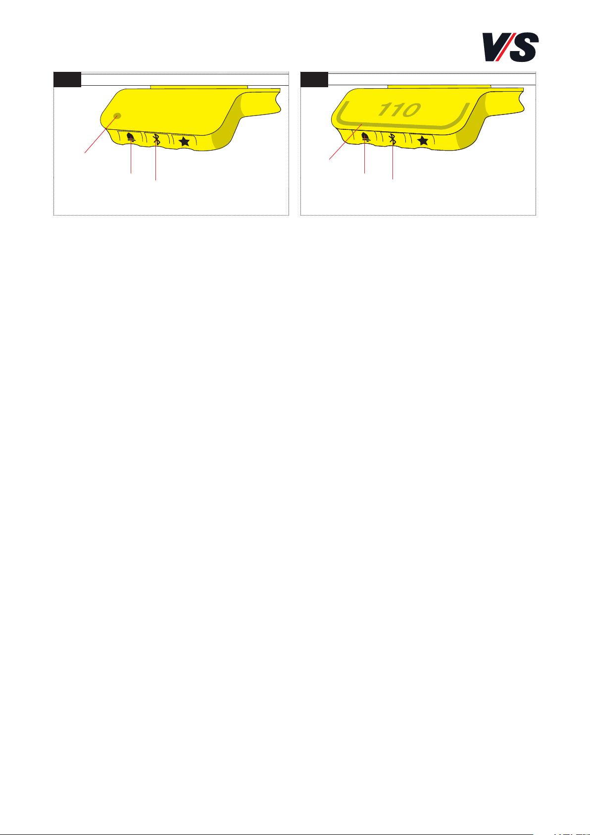
4.5 Erinnerung / Einstellen des Erinnerungsintervalls
Handschalter Memory und Memory-Display [Bild 1-2]:
Die Handschalter haben auf der linken Seite eine „Erinnerungstaste“
(2) – symbolisiert durch eine Glocke. Durch Drücken dieser Taste wird
das Intervall eingestellt, wie oft Sie eine Erinnerung zum Positionswechsel erhalten möchten.
Beim Handschalter Memory leuchtet die LED (3) in drei verschiedenen
Intensitäten auf, die jeweils ein Intervall darstellen. Beim Handschalter
Memory-Display stellt jeder weiße Block der Lichtleiste (4) ein Intervall
dar.
1 2
(3)
(4)
(2)
(1)
(1)
(2)

16
Die drei Intervalle sind:
-- Intervall 1: Erinnerung nach 55 Minuten Sitzen
-- Intervall 2: Erinnerung nach 50 Minuten Sitzen
-- Intervall 3: Erinnerung nach 45 Minuten Sitzen
Das gewählte Standardintervall erinnert nach 55 Minuten, was
bedeutet, dass die LED in der schwächsten Intensität bzw. nur ein
Balken der Lichtleiste weiß leuchtet. Schalten Sie einfach zwischen
den Intervallen durch Drücken der „Glocke“-Taste um. Wenn die LED
bzw. der Balken nicht leuchtet, ist die Erinnerung ausgeschaltet.
Mit Hilfe der Desk Control App ist es möglich, die drei Intervalle auf
benutzerdefinierte Werte zu personalisieren.
- Reset Erinnerung
Durch Drücken des "Glocken"-Symbols für 8 Sekunden kann die Erinnerungsfunktion auf die Standardwerte zurückgesetzt werden. Je nach
Modell blinkt die LED rot bzw. zeigt das Display einen Countdown und
der Balken blinkt um anzuzeigen, wann der Vorgang abgeschlossen ist.
- LED Erinnerung
Der Status des Schreibtischnutzers wird durch die LED in der linken
unteren Ecke bzw. durch die Lichtleiste angezeigt.
Der Status hängt vom gewählten Erinnerungsintervall ab. Wechselt
der Anwender die Position entsprechend dem Intervall in einer angemessenen Zeitspanne, pulsiert die LED bzw. die Lichtleiste langsam
grün. Wenn das Sitz-Intervall abläuft, verwandelt sich das langsam
pulsierende Grün für eine Minute in ein schnell pulsierendes Grün
und danach in ein statisches Orange – dies ist ein Hinweis für den
Anwender, den Schreibtisch nach oben zu fahren und aufzustehen.
In der Stehhöhe pulsiert die LED bzw. die Lichtleiste bis zu einer
möglichen Pause grün. Wenn der Schreibtisch wieder nach unten in
die Sitzposition gefahren wird, pulsiert die LED grün, bis sich die
Erinnerungsfunktion wieder ausschaltet.
Nach 4 Stunden ohne Aktion schaltet sich die LED bzw. die Lichtleiste
aus. Wenn das Handschalter gedrückt wird, schaltet sich das
grüne Licht wieder ein.

17
Bitte beachten Sie: Ist die LED für Erinnerungen aktiviert, befindet sich
der Handschalter nicht länger im Standby-Modus, solange das Licht eingeschaltet/aktiv ist.
4.6 Container- und Regal-Stopp
Auf-Ab mit Memory und Auf-Ab mit Memory und Display
Diese beiden Funktionen können eingesetzt werden, um den Verfahrberich des Tisches einzuschränken (wenn z.B. ein Container unter
dem Tisch steht). Eine Container-Stopp-Position kann in der unteren
Hälfte des Fahrbereiches eingestellt werden, eine Regal-Stopp-Position
in der oberen Hälfte. Wenn eine Container-Stopp-Position gesetzt
ist, fungiert diese als neue untere Endlage. Eine Regal-Stopp-Position
entspricht einer neuen oberen Endlage des Fahrbereichs. Um eine
Container- / Regal-Stopp-Position zu speichern, gehen Sie wie folgt vor:
- Fahren Sie den Schreibtsich auf eine bevorzugte Position durch
Drücken nach oben oder unten.
- Für eine Container-Stopp-Position halten Sie für 8 Sekunden die
Bluetooth®-Taste gedrückt und drücken gleichzeitig den Handschalter
nach unten.
- Für eine Regal-Stopp-Position halten Sie für 8 Sekunden die Bluetooth®-Taste gedrückt und drücken gleichzeitig den Handschalter
nach oben.
- Die LED leuchtet 2 mal weiß zur Bestätigung.
- Um die Stopps zu löschen, halten Sie die Stern- und Glocken-Taste
für 8 Sekunden gedrückt.
18
5. Fehlerbehebung
5.1 Der Tisch verfährt nicht
- Warten, ob die maximale Einschaltdauer (siehe Kapitel 8) überschritten
wurde und dadurch die Einschaltdauerbegrenzung aktiviert wurde.
- Prüfen Sie, ob alle Kabel richtig eingesteckt sind (bzw. ob Strom
vorhanden ist).
- Vergewissern Sie sich, dass die Belastung (siehe Kapitel 8) auf dem
Tisch nicht zu hoch ist.
- Vergewissern Sie sich, dass keine Hindernisse den Verfahrweg
blockieren.
5.2 Resetfahrt (Initialisierung)
Achtung! Bei Störungen ist ein manueller Reset (Initialisierung)
durchzuführen.
Die Reset-Position ist bei einer Tischhöhe von =< 650 mm erreicht. Bei
jeder Bedienung hat der Benutzer sich grundsätzlich davon zu überzeugen,
dass der Verfahrweg (spez. unter dem Tisch) frei von Hindernissen ist. Das
System wird durch Kippen und Halten des Handschalter nach unten initialisiert. Dieser muss gedrückt gehalten werden, bis die Antriebe die untere Endlage erreicht haben. Sobald die Antriebe in der untersten Endlage gestoppt haben, muss der Handschalter für 2-3 Sekunden losgelassen
werden, um dann für weitere 5 Sekunden gedrückt gehalten zu werden.
Danach ist die Initialisierung abgeschlossen. Das System wird während
der Initialisierung 5 mm abgesenkt und wieder angehoben. Bitte lassen
Sie den Handschalter während der Initialisierung auf keinen Fall los.
Achtung! Wenn der Handschalter losgelassen wird, bevor der Vorgang
komplett abgeschlossen ist, wird die Initialisierung unterbrochen und
muss neu begonnen werden. Bei einer abgebrochenen Initialisierung
ist keine Aufwärtsfahrt des Systems möglich.
Achtung! Wenn der Handschalter gesperrt ist, leuchtet im Display
ein Schloss, das Licht wird für eine Sekunde rot. Zum Entsperren des
Handschalters beachten Sie bitte Punkt 4.4.
19
Sollte ein Sicherheitsstopp eingestellt sein, so muss beachtet werden,
dass das System in die unterste Endlage gefahren werden muss, bevor
die Initialisierung gestartet werden kann. Um den eingestellten Sicherheitsstopp zu überwinden, muss nach Erreichen des Vorstopps ein zweites
Mal der Handschalter nach unten betätigt werden, damit das System mit
ca. der Hälfte der Antriebsgeschwindigkeit in die unterste Endlage weiterfährt. Nach erfolgreichem Reset verfährt das System die ersten beiden
Male in der obersten Stellung um ca. 3 mm zurück.
5.3 Fehlercodes
Am Display wird eine Fehlernummer angezeigt
Fehlercode Bedeutung Behebung/Beschreibung
E-01 Positionsverlust Führen Sie einen Reset durch
E-16 Tastenfehler Falsche Tastenkombination auf Hand-
schalter gedrückt, Tastenkombination
wird nicht unterstützt
E-59 Auahrschutz Auahrschutz des Tisches wurde ausgelöst
Kanal 1 Verfahrweg überprüfen,
Hindernisse entfernen
E-60 Auahrschutz Auahrschutz des Tisches wurde ausgelöst
Kanal 2 Verfahrweg überprüfen, Hindernisse entfernen
Achtung! Innerhalb der Garantiezeit ist der Austausch der Antriebstechnik nur durch den VS-Kundendienst (VS-KD) zulässig.
Wichtig! Für weitere Fragen wenden Sie sich an ihren zuständigen
VS-Fachberater bzw. an die entsprechende VS-Niederlassung.
5.4 Fehlerbehebung Kunde / VS Kundendienst
Achtung! Der Austausch der Antriebstechnik ist nur durch den
VS-Kundendienst (VS-KD) zulässig!
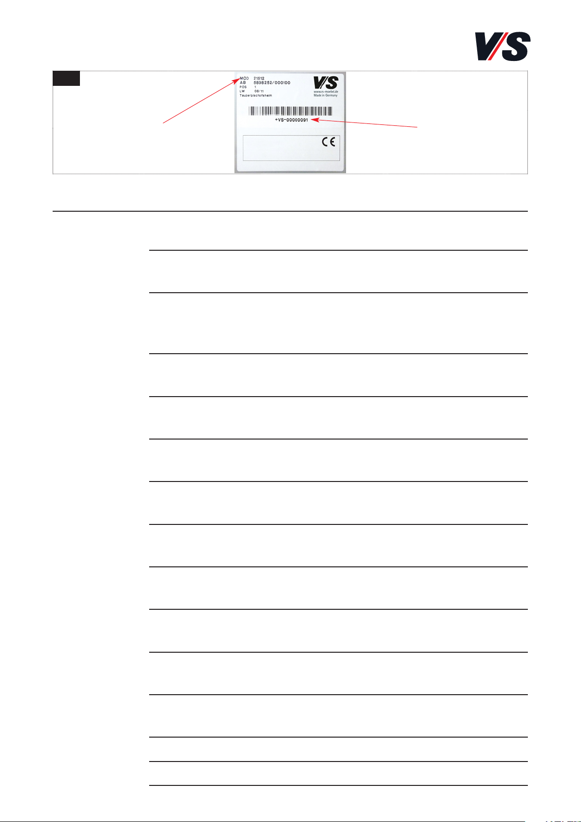
Bei der Kontaktaufnahme mit dem VS-Kundendienst bitte die Modell-Nr.
und die Serien-Nr. des Tisches bereithalten. Diese befindet sich auf einem
Typenschild auf der Tischplattenunterseite [Bild 4].
20
Fehler Fehlerbeschreibung Fehlerbehebung
Antriebe Steuerung nicht eingesteckt Netzkabel einstecken
funktionieren
nicht Antrieb nicht eingesteckt Motorkabel einstecken
Schlechter Steckkontakt Tischhandschalter, Netz-
oder Motorenstecker
richtig einstecken
Antrieb defekt Wenden Sie sich bitte
an den Kundendienst
Steuerung defekt Wenden Sie sich bitte
an den Kundendienst
Tischhandschalter defekt Tischhandschalter
auswechseln
Antrieb läuft Steuerung defekt Wenden Sie sich bitte
nur in einer an den Kundendienst
Richtung Tischhandschalter defekt Tischhandschalter
auswechseln
Steuerung Steuerung nicht eingesteckt Netzkabel einstecken
oder
Tischhand- Tischhandschalter nicht Tischhandschalter
schalter angesteckt anstecken
funktioniert Steuerung defekt Wenden Sie sich bitte
nicht an den Kundendienst
Netzkabel defekt Wenden Sie sich bitte
an den Kundendienst
Tischhandschalter defekt Tischhandschalter auswechseln
Schlechter Steckkontakt Stecker richtig einstecken
Serien-Nr.Modell-Nr.
4

21
(3)
(2)
(1)
(1)
1 2
6. Tische mit Kurbelhöhenverstellung
Sitz-/Sitzverstellung: 65 - 85 cm pro Kurbelumdrehung 3 mm
Sitz-/Sitzverstellung: 65 - 85 cm pro Kurbelumdrehung 12 mm
Sitz-/Stehverstellung: 65 - 125 cm pro Kurbelumdrehung 40 mm
Die Höheneinstellung [Bild 1] erfolgt durch Drehen der Handkurbel (1);
im Uhrzeigersinn nach oben - gegen den Uhrzeigersinn nach unten.
Die Handkurbel (1) ist in der Parkposition (2) unter der Tischplatte
arretiert [Bild 2]. Zur Verstellung die Kurbel aus der Arretierung lösen und
nach vorne ziehen, bis sie in der Funktionsstellung (3) einrastet [Bild 2].
Achtung! Nach dem Verstellen der Tischhöhe muss die Handkurbel
wieder in der Parkposition arretiert werden.

22
(1)
(2)
(3)
(4)
(5)
(5)
(1)
(2)
(3)
(5)
(5)
(4)
(4)
1
2
3
7. Tischmanagement
7.1 Tischplatte verschieben/abnehmen
Zum Verschieben [Bild 1-2] der Platte den Sicherungshebel (1) auf der
Unterseite kurz nach links schieben, um den ersten Sicherungsstopp (2)
zu lösen. Die Tischplatte bis zum zweiten Stopp (3) führen. In dieser
Stellung ist die Kabelwanne zugänglich. Um die Tischplatte abzunehmen,
ist sie erneut zu entriegeln und über die zweite Sicherung zu ziehen.
Achtung! Beim Verschieben der Tischplatte die Elektrifizierungsklappe immer geönet halten.
Zum Abnehmen/Einsetzen [Bild 3] die Führungen (4) an der Plattenunterseite an den beiden Tischkonsolen (5) ausrichten. Eingesetzte Platte
bis zum ersten Stopp schieben und den Sicherungshebel betätigen. Durch
Entriegeln des zweiten Sicherungsstopps Platte in Endstellung schieben.
Achtung! Vor dem Verschieben/Abnehmen muss die Tischplatte
abgeräumt werden.

23
1 2
(1)
(2)
(5)
(4)
(3)
(4)
(6)
(3)
7.2 Kabelwannen
Zum Abklappen muss die Metallkabelwanne [Bild 1] entriegelt werden.
Dazu durch die Aussparungen (1) greifen und die Sperrriegel (2) an der
linken und rechten Seite gleichzeitig nach innen schieben.
Zum Schließen die abgeklappte Seite der Metallkabelwanne nach oben
führen und in die Verriegelung hörbar einrasten lassen.
Die Textilkabelwanne [Bild 2] ist beidseitig abklappbar. Zum Önen
einen Halterungsstab (3) der Wanne aus der Clip-Verbindung (4) nach
außen lösen. Geschlossen wird die Textilwanne wieder durch Aufclipsen
des Halterungsstabes.
Achtung!
Zugentlastung der Kabelwannen benutzen.
Die Zugentlastungen (5) der Metallkabelwannen können auf dem Rand
oder im Innenraum positioniert werden. Bei Textilkabelwannen ist die
Zugentlastung (6) am Befestigungsbügel angebracht.

24
(1)
(1)
(4)
(5)
(3)
(5)
(3)
(2)
(1)
3
4
1 2
5
7.3 Kabelketten
Kabelkette Cube (1) für Metallkabelwannen wird bei Tischen mit C-Fuß
[Bild 1-2] von unten in die Wanne geführt und mit dem Führungsstab
(2) von oben fixiert. Bei Tischen mit T-Fuß [Bild 3] wird die Kabelkette
Cube mit Magnet außen an der Metallkabelwanne angebracht. Zur kontrollierten Führung wird die Kette mit zwei integrierten Magneten am Tischfuß fixiert.
Die runde Kabelkette (3) wird bei der Metallkabelwanne [Bild 4] mit
dem Universalhalteclip (5) in die Stanzung (4) eingehängt. Bei der
Textil kabelwanne [Bild 5] wird der Universalhalteclip (5) aufgesteckt.
Der textile Kabelschlauch wird mit Magnet direkt an der Metallkabelwanne oder bei der Textilkabelwanne an der Konsole befestigt.

25
1 2
3
(1)
(2)
(3)
7.4 CPU-Halter, ThinClient-Halter, Druckerboard
Der CPU-Halter (1) (fix oder verstellbar) kann links oder rechts befestigt
und nach innen wie nach außen ausgerichtet werden [Bild 1].
So positionieren, dass Rechner nicht mit Tischsäule kollidiert.
Der ThinClient-Halter (2) für Mini-PCs wird an der Tischkonsole links
oder rechts angeschraubt [Bild 2].
Das Druckerboard (3) kann links oder rechts am Tischbein angebracht
werden [Bild 3]. Zur Montage die Tischplatte abnehmen, siehe Punkt 6.1.
Halterung an Tischtraverse von oben und seitlich verschrauben. Für Verschraubung oben die Flachkopfschrauben nutzen.

26
(1)
(2)
(2)
(1)
(1)
(2)
(3)
(6)
(6)
(4)
(5)
1
2
3
4
7.5 Tischabstandshalter [Bild 1-2]
Tischabstandshalter für die seitliche (1) und die frontale (2) Verkettung
von Tischen so positionieren, dass die Tischfüße in die entsprechende
Aussparung greifen. Der Verdrehschutz (3) des Distanzhalters muss in die
entsprechende Önung an der Unterseite des Tischfußes einhaken.
Bei Einsatz von beiden Tischabstandshalter-Typen an einem Tischfuß
wird der seitliche Abstandshalter über dem frontalen angeordnet.
Achtung! Tischabstandshalter gewährleisten den erforderlichen
Sicherheitsabstand von 25 mm.
7.6 Elektrifizierungsklappe/E-Box [Bild 3-4]
Der Steckdosenblock (4) in der Elektrifizierungsklappe/E-Box (5) kann
zur Verkabelung des Tisches durch Abziehen aus dem Gehäuse (6) gelöst
werden. Zum Aufbringen den Block andrücken und in der Fassung hörbar
einrasten lassen.

27
1 2
3
8. Doppeltische Twin
Bei Doppeltischen Twin mit mitfahrenden Blenden ist folgendes zu beachten
– Gerade mitfahrende Blenden müssen links und rechts im Wangen-
bereich eingerückt werden, um eine Klemmstelle zwischen Wange
und Blende zu vermeiden. Sicherheitsabstände von 25 mm sind einzuhalten [Bild 1].
– Eine mitfahrende Eckblende (1) von ScreenPlus ist nicht zulässig
[Bild 2]!
– Eine Trogwanne (2) ist bei mitfahrenden Blenden (3) nicht zulässig
[Bild 3]!
Achtung! Beim Fahren des Antriebs ist darauf zu achten, dass keine
Gegenstände oder Körperteile eingeklemmt werden!
(2)
(1)
(3)

28
9. Technische Daten
Bezeichnung C-/T-Fuß
Die Höhe ergibt sich je nach
Wahl der Ausführung: von 65 bis 125 cm
Maximale Hublast bei 75 kg (vollflächig)
Einschaltdauer 2 Minuten “ON” und
18 Minuten “OFF”
Sicherheitsabschaltung
Umgebungstemperatur darf +0°C nicht unterschreiten
zum Betrieb und + 35° C nicht überschreiten
Sicherheitsbereich Endlage ca. 11 cm über
unterster Tischhöhe
Geräuschentwicklung < 50 dB(A)
Hubgeschwindigkeit 38 ± 2 mm/sek
Relative Luftfeuchte 5 bis 85 %
Spannungsversorgung 230 V
Leistungsaufnahme 300 W im Betrieb mit Last
Schutzart IP-Klasse IPX0
Schutzklasse II
Frequenzbereich 50 Hz
Standby-Leistung, primär (typisch) 0,1 W

29
1
ca. 35°
50-60 cm
≥90°
≥90°
≥90°
65-76 cm 65-125 cm
10. Hinweise zur Ergonomie
- Sitz-/Steharbeitsplätze lassen eine besonders flexible Arbeitsorgani-
sation zu. Durch die Möglichkeit, die gesamte Arbeitsfläche mit dem
Bildschirm und den Eingabegeräten in der Höhe zu verstellen, kann
praktisch jede Tätigkeit im Sitzen oder im Stehen ausgeübt werden.
- Empfehlungen:
A. Häufigeres Stehen von kurzer Dauer ist günstiger als lange Stehphasen.
B. Statisches Stehen sollte vermieden werden.
C. 2 bis 4 Haltungswechsel pro Stunde sind empfehlenswert [Bild 1].
- Der Bildschirm sollte so aufgestellt sein, dass keine Reflexionen auf
dem Monitor durch z. B. Beleuchtung oder Fenster entstehen. Am
sinnvollsten ist es, den Bildschirm zwischen zwei Leuchtbändern zu
positionieren und die Blickrichtung parallel zum Fenster auszurichten.
Die oberste Zeile auf dem Bildschirm sollte nicht oberhalb der
horizontalen Sehachse liegen. Für eine angenehme Kopfhaltung,
sollte der Blickwinkel um etwa 35° zur Bildschirmmitte abgesenkt
werden [Bild 1].
- Die Höhenverstellung ermöglicht auch eine einfache Einstellung
der richtigen Sitzhöhe. Verwenden Sie möglichst nur Sitzmöbel, die
ergonomisch geformt und höhenverstellbar sind. Die Rückenlehne
sollte die Lendenwirbel optimal stützen. Beachten Sie die Herstellerhinweise, um den Stuhl genau an Ihre Körpergröße und Figur anzupassen.
Sitzen Stehen

30
- Der Rat der Europäischen Gemeinschaft hat für die Ergonomie am
Arbeitsplatz bestimmte Richtlinien und Regeln aufgestellt, die der
EG-Richtlinie 90/270/EWG unterliegen.
- Einen Leitfaden zur Gestaltung von Bildschirm- und Büroarbeitsplätzen
hat die Verwaltungs-Berufsgenossenschaft in der Schriftenreihe
Prävention herausgegeben (DGUV 215-410).
Nähere Informationen: www.vbg.de

31
11. EU-Konformitätserklärung

32

33
Contents.
General safety instructions 32
Safety instructions 32
1. General comments: 37
1.1 Importance of the Operating Instructions: 37
1.2 Intended use (scope): 37
1.3 Incorrect use: 38
1.4 Scope of delivery, assembly, transport, storage: 38
1.5 Transfer and Disposal: 39
2. Safety notes. 40
3. Collision protection 42
3.1 Information on collision protection 42
3.2 Notes on use 42
4. Using the table handswitch. 43
4.1 Height adjustment 43
4.2 Saved positions 44
4.3 Button lock/safety mechanism in private premises 45
4.4 Bluetooth® connection 46
4.5 Reminder / Setting the reminder interval 46
4.6 Container and shelf stop 48
5. Troubleshooting 48
5.1 The table does not move 48
5.2 Reset travel (initialization) 49
5.3 Error codes 50
5.4 Troubleshooting – customer / VS Customer Service 50
6. Tables with winding handle for height adjustment 52
7. Table management 53
7.1 Moving/removing the table top 53
7.2 Cable trays 54
7.3 Cable chains 55
7.4 CPU holder, ThinClient holder, printer board 56
7.5 Table spacers [Figure 1-2] 57
7.6 Electrical connection flap/E-box [Figure 3-4] 57
8. Twin dual desk 58
9. Technical data 59
10. Notes on ergonomic use 60
11 . EU-Konformitätserklärung 62

34
General safety instructions:
The following symbols and notes are used in our Instructions:
Important!
This symbol indicates an important assembly note.
Caution!
This symbol indicates a very important note.
Safety instructions:
Caution! Please read these instructions carefully before starting to
use the system and keep them in a safe place for future reference.
They are also available via download: (see title in header).
Caution! The seated/standing workplace may only be used in private
premises if fitted with a special locking mechanism (see section 4.3).
It is essential that this locking mechanism is activated to prevent
unauthorised use!
Caution!
Children must not play with the equipment.
Caution! Rodents should be kept away from electrical operating
equipment and their power supply lines. Damaged lines may pose a
risk to humans and animals.
Caution! It is essential to follow the safety instructions! Incorrect
operation of the system may cause risks to persons and property!
Important! Oce furniture containing electrical installations must
be inspected in accordance with the accident prevention regulations
and generally acknowledged rules of sound practice, and the specified inspection intervals must be adhered to!

35
Caution! When using the drive, make sure that no objects (e.g. items
of furniture) or body parts are trapped!
When operating the table, the user must always make sure that no
other persons are present at the table and that the travel path is
free from obstacles. A minimum distance of 25 mm from nearby objects must be maintained in order to avoid the possibility of trapping
and shearing!
Caution! Before taking the system into operation, make sure that
the operating voltage of the system corresponds to the local power
supply. The system is in operation as soon as it is connected to the
power supply.
Caution! The collision protection is not an entrapment or personal
protection mechanism! For physical reasons, “soft” obstacles may
only be poorly detected and evaluated or may not be detected at all!
If the table travels against an obstacle then it is possible that the
obstacle may suer damage because the table travels against it at
its nominal speed!
Caution! Before using the table for the first time or in the event of a
malfunction, a manual reset (initialization) must be performed.
Caution! If the button is released before the operation has been
completed then initialization will be interrupted and has to be repeated. If initialization is interrupted then the system cannot travel
upwards.
Caution! When using the drive, make sure that no objects or body
parts are trapped!

36
Caution! If the handswitch is locked, a padlock lights up in the display. The light turns red for one second.
Caution! If the table travels against an obstacle then it is possible
that the obstacle may be damaged because the table travels against
it at its nominal speed!
Caution! During the warranty period, the drive elements may only
be replaced by the VS Customer Service (VS-KD).
Important! If you have any further questions, please consult your
responsible expert VS consultant or the appropriate VS branch.
Caution! After the table height has been adjusted, the manual winding handle must be locked in the park position again.
Caution! When moving the table top, always keep the electrical connection flap open.
Caution! Clear all items from the table top before moving or
removing it.
Caution!
Use the strain relief mechanisms for the cable trays.
Caution! Height-adjustable tables pose a risk of crushing. Table
spacers ensure that the necessary safety distance is observed.

37
1. General comments:
Caution! Please read these instructions carefully before starting to
use the system and keep them in a safe place for future reference.
They are also available via download:
1.1 Importance of the Operating Instructions:
- Knowledge of the basic notes on safety and the safety instructions is
vital in order to ensure the safe handling and fault-free operation of
this seated/standing workplace.
- These Operating Instructions contain the most important information
to ensure the safe use of the seated/standing workplace.
- Anyone who works at the seated/standing workplace (e.g. main-
tenance personnel, operators, technical managers, electricians) must
be familiar with these Operating Instructions, and in particular the
notes on safety.
- In addition, the rules and regulations on accident prevention that
apply at the place of use must be adhered to.
- All the information in these Instructions is valid at the time of printing.
Product technology or design may be subject to change in order to
bring about improvements to the product.
1.2 Intended use (scope):
The current seated/standing workplace is an oce work table/screen
workstation that has been designed exclusively for seated and standing
oce activities and is therefore intended for this use only. Any other use or
use beyond the intended scope (e.g. in workshops, storage areas, explosive
areas, damp locations) is considered to be non-intended use. The company
VS Vereinigte Spezialmöbelfabriken GmbH&Co.KG accepts no responsibility
for any loss or damage resulting from such use.
Caution! The seated/standing workplace may only be used in private
premises if fitted with a special locking mechanism (see section 4.3).
It is essential that this locking mechanism is activated to prevent
unauthorised use!

38
1.3 Incorrect use:
- This appliance can be used by children aged from 8 years and above
and persons with reduced physical, sensory or mental capabilities or
lack of experience and knowledge if they have been given supervision
or instruction concerning use of the appliance in a safe way and
understand the hazards involved. Cleaning shall not be made by
children without supervision.
- Never use the seated/standing workplace to lift persons or loads.
- Only load the seated/standing workplace up to the maximum load per-
mitted across the full surface of the table (see sec. 8 “Technical data”).
Caution!
Children must not play with the equipment.
Caution! Rodents should be kept away from electrical operating
equipment and their power supply lines. Damaged lines may pose a
risk to humans and animals.
1.4 Scope of delivery, assembly, transport, storage:
- VS Vereinigte Spezialmöbelfabriken GmbH & Co KG delivers the
seated/standing workplace fully assembled.
- During the warranty period, repairs may only be performed by
employees of VS Vereinigte Spezialmöbelfabriken GmbH & Co. KG.
- The assembly of subsequently supplied accessories and/or conversi-
on operations made necessary by them may only be performed by
persons who are perfectly familiar with the assembly instructions.
Only original VS accessories may be used.
- If you have to move the seated/standing workplace, make sure that
the plug has been disconnected from the mains and that there are
no objects on the table.
- Only carry the seated/standing workplace by its frame or use a
trolley (furniture trolley).
- The seated/standing workplace may only be moved by two persons
working together and it must be in its retracted state. Do not under any circumstances pull or tip the seated/standing workplace.

39
- If tables are stored, a maximum
of one table may be stacked on
another. Avoid damage when
doing this. When stacked, the
table must be in its lowest
position. Only store tables
in their normal working position [Figure 1].
1.5 Transfer and Disposal:
- If the product is transferred to another party then it must be
accompanied by these Instructions. Please contact your responsible
local authority department regarding environmentally friendly
disposal.
- The indicated electric and electronic components must not be
disposed of with the ordinary waste.
They must be removed from the furniture unit before the
unit is sent for disposal. They are to be disposed of at
authorized collection and return points.
1

40
2. Safety notes.
Caution! It is essential to follow the safety instructions! Incorrect
operation of the system may cause risks to persons and property!
- Never open the housing of the controller or of the power pack! Un-
authorised opening of the housing and incorrect repairs may cause
risks for users and will render the warranty null and void. The electrical equipment may only be opened and repaired by the VS Customer Service!
- In the case of malfunctions such as the emission of smoke or odours
or in the event of unusual noises or visible external damage, do not
continue to use the equipment. Disconnect the power plug from the
mains and inform the VS Customer Service (Tel.: +49 (0)9341/880)!
- The mains connection line to the mains socket must be located close
to the table and must be easily accessible.
- Electrical supply lines must not be exposed to any risk of crushing or
any strain due to bending or pulling! You must also make sure that the
cables are long enough to accommodate the up-and-down movement
of the table.
- When establishing electrical connections at oce furniture, observe
the following guidelines: Electrical connections may only be established by specialist personnel!
Important! Oce furniture containing electrical installations must
be inspected in accordance with the accident prevention regulations
and generally acknowledged rules of sound practice, and the specified
inspection intervals must be adhered to!
- Protect electrical components against moisture and dripping or
splashed water.
- The controller and table handswitch may only be cleaned using a
dry or slightly moistened cloth.

41
Caution! When using the drive, make sure that no objects (e.g. items
of furniture) or body parts are trapped!
When operating the table, the user must always make sure that no
other persons are present at the table and that the travel path is free
from obstacles. A minimum distance of 25mm from nearby objects
must be maintained in order to avoid the possibility of trapping and
shearing!
- The table may only be operated with the supplied/installed controller
and power supply unit!
- To protect against overvoltages, for example due to storms, it is
advisable to install surge protection. Please seek the advice of an
electrical fitter.
- Observe the specifications regarding operating times, temperature
etc. (see section 8).
Caution! Before taking the system into operation, make sure that
the operating voltage of the system corresponds to the local power
supply. The system is in operation as soon as it is connected to the
power supply.
- Cleaning must not be performed by children unless they are supervised.
- If the equipment's mains power line is damaged, it must be replaced
by the manufacturer, the manufacturer's customer service department
or a similarly qualified person in order to avoid any risks.
The warranty applies only if the product is used as intended. The product
is maintenance-free.

42
3. Collision protection
Caution! The collision protection is not an entrapment or personal
protection mechanism! For physical reasons, “soft” obstacles may
only be poorly detected and evaluated or may not be detected at all!
If the table travels against an obstacle then it is possible that the
obstacle may suer damage because the table travels against it at
its nominal speed!
3.1 Information on collision protection
- If the table meets and detects an obstacle when traveling either
upwards or downwards then the upward travel protection prevents
the table from inclining or continuing its travel. If an obstacle is
detected then the table stops moving and reverse travel is initiated
automatically (dierence in reverse travel: approx. 5 cm)
3.2 Notes on use
- Start/acceleration phase: Once travel has started, obstacles can only
be detected after travel of approximately 2 cm, after the nominal
speed has been reached.
- Load: If the table is not subject to any load then obstacles cannot
be or can only be poorly de
- Soft obstacles: Soft obstacles include all types of obstacle that
initially give way when the table travels against them, for example
as in the case of human body parts, upholstered chairs etc. Soft
obstacles cannot be or can only be poorly detected.
- Operating time restriction: The electronics monitor how long the
drives have been operating. If the maximum permitted time is
exceeded then the electronics do not permit continued operation
of the drives (see section 8).

43
4. Using the table handswitch.
4.1 Height adjustment
Three dierent handswitches with three dierent functions are used to
adjust the table height:
Height adjustment
Tilt the handswitch (1) upwards to move the table
up. Tilt the handswitch (1) downwards to move
the table down. The drives continue to run for as
long as you hold the handswitch (1) in a tilted
position. The current height of the table is displayed in cm in the handswitch memory display.
- Soft start/Soft stop: The drives are operated at reduced power for a
short time after starting or before stopping.
- Safety area: For safety reasons, the table controller is equipped with
two lower stops (safety area) ex works (see section 8). In usual travel
operation, a first lower stop is traveled to before the bottom position
is reached. Only when the handswitch is pushed again does the table
travel to its lowest position at reduced speed.
Standard handswitch
[Figure 1]
• Up/down function
Memory handswitch
[Figure 2]
• Up/down function
• 2 saved positions
• Memory function via
LED
• Bluetooth®
Handswitch Memory
display [Figure 3]
• Up/down function
• 4 saved positions
• Memory function via
light strip
• Bluetooth®
• Display
1 2 3
4
(1)

44
4.2 Saved positions
- Memory and memory display handswitch:
Saving positions 1 and 2
On the right-hand side of the handswitches [Figure 1], there is a
“Save” button (1) which is indicated by a star .
- Move the desktop to a position you like to use and press the star
button (1) for 2 seconds. On the memory handswitch, the LED (2)
flashes; on the memory display handswitch [Figure 2], the light strip
(3) flashes twice to indicate that the position is being memorised.
- Memory display handswitch only [Figure 2]: The display indicates
the saved position with a star and the position number. The number
next to the star corresponds to the sequence in which the positions
were saved. First position saved: A star with a “1” next to it (4).
In this way, the positions “1” and “2” are saved.
- If the user moves the desktop to a dierent position and then saves
this position, this position overwrites the saved position closest to
the current position.
- Additional function of the memory display handswitch [Figure 2]:
Saving positions 3 and 4
The handswitch can be used to save four positions. If you press the
star button (1) briefly, the display indicates one of the four saved
positions. You can repeatedly briefly press the star button (1) to
switch between the four saved positions and choose the number
under which the current position is to be saved. For example, the
user wants to save the current position as position 3: Keep pressing
and releasing the star button until the “star” appears in the display
with “3” next to it. Now repeat the same memory operation as
described above: Press the star for 2 seconds to save the position.
1 2
(1) (1)(4)
(2)
(3)

45
- Moving to saved positions
After the positions have been saved, it is easy to move to them by
pressing and holding down the handswitch. When a saved position
is reached, the table stops automatically.
In this way, the user can switch between standing and sitting without
having to look at the handswitch.
- When the table stops at a saved position, the user can press the
handswitch for one second and the table travels past the saved
position in the direction in which the handswitch was pressed.
Alternatively, the user can release the handswitch and then press it
again in order to travel past the saved position.
- Deleting saved positions
Press the star button for 8 seconds to delete all the saved positions.
The LED or the light strip flashes red when the operation is complete.
4.3 Button lock/safety mechanism in private premises
The handswitch (VS part no. 88-668) must be secured using a locking
function when the table is used in private premises. If this function is
not present, please contact the:
VS Customer Service (Tel. +49 (0)9341/880)!
Caution! If the handswitch is locked, a padlock lights up in the
display. The light turns red for one second.
To unlock this control element [Figure 1], press the buttons bell (1) -
Bluetooth (2) - star (3) directly after one another
(max. 1 second between presses). When the
handswitch is unlocked, the height is shown in
the display. The handswitch is now activated.
You can adjust the table as you wish by pressing
the handswitch.
1
(1)
(2)
(3)

46
The handswitch then remains activated for a further 5 seconds. If you
do not press any further buttons during this time then the handswitch
is locked again.
4.4 Bluetooth® connection
Memory and memory display handswitches [Figure 1-2]:
Download the Desk Control App that is suitable for your device from
the App Store or Google Play and connect the app to your device:
Press the central Bluetooth® button (1) for 2 seconds to activate
connection mode.
A blue flashing light in the LED (3) or in the light strip (4) shows
that connection mode is active.
In the memory display handswitch, the display shows the Bluetooth
ID of the desk, which consists of “DESK” followed by a four-digit
number. Search for this ID in the list of nearby desks.
4.5 Reminder / Setting the reminder interval
Handswitche memory and memory-display [Figure 1-2]:
The handswitches have a “reminder button” on the left-hand side
(2) – this is indicated by a bell. Pressing this button sets the interval
after which you want to be reminded to change position.
In the memory handswitch, the LED (3) lights up in three dierent
intensities, each of which represents an interval. In the memory
display handswitch, each white block on the light strip (4) represents
an interval.
1 2
(3)
(4)
(2)
(1)
(1)
(2)

47
The three intervals are:
-- Interval 1: Reminder after 55 minutes of sitting
-- Interval 2: Reminder after 50 minutes of sitting
-- Interval 3: Reminder after 45 minutes of sitting
The standard interval selected by default reminds you after 55 minutes.
In this case the LED glows with the weakest intensity or only one bar
lights up in the light strip. You caneasily switch between the intervals
by pressing the “bell” button. If the LED or bar does not light up then
the reminder function is deactivated.
You can use the Desk Control App to customise the three intervals to
user-defined functions.
- Resetting the reminder
You can reset the reminder function to the default values by pressing
the “bell” symbol for 8 seconds. Depending on the model, the LED will
glow red or the display will indicate a countdown and the bar will
flash to show when the operation has been completed.
- LED reminder
The status of the user of the desk is indicated by the LED in the bottom
left corner or by the light strip.
The status depends on the selected reminder interval. If the user
changes the position in an appropriate period in accordance with the
interval then the LED or light strip slowly flashes green. When the
sitting interval expires, the slow flashing green signal starts flashing
green quickly and then turns constant orange – this tells the user
that it is time to move the desk upwards and stand up.
When the desk is at standing height, the LED or light strip flashes
green until interrupted. When the desk is moved back down into sitting
position, the LED flashes green until the reminder function becomes
deactivated again.
After 4 hours without any action, the LED or light strip switches o.
When the handswitch is pressed, the green light comes on again.
Please note: If the reminder LED is activated then the handswitch is no
longer in standby mode as long as the light is on/active.

48
4.6 Container and shelf stop
Up/down with memory and up/down with memory and display
These two functions can be used in order to limit the travel range
of the desk (for example, if there is a container under the desk).
A container stop position can be set in the lower half of the travel
range and a shelf stop position in the top half. If a container stop
position is set then this acts as a new lower stop position. A shelf
stop position corresponds to a new upper stop position for the travel
range. Proceed as follows to save a container/shelf stop position:
- Move the desk to a position you want by pressing up or down.
- To set a container stop position, hold the Bluetooth® button down
for 8 seconds and simultaneously press the handswitch downwards.
- To set a shelf stop position, hold the Bluetooth® button down for
8 seconds and simultaneously press the handswitch upwards.
- The LED flashes white twice to confirm.
- To delete these stop positions, press and hold down the star and bell
buttons for 8 seconds.
5. Troubleshooting
5.1 The table does not move
- heck whether the maximum operating time has been exceeded (see
section 8) and the operating time restriction has been activated.
- Check whether all the cables are inserted correctly (and if necessary
whether there is a functioning electricity supply)
- Make sure that the load (see section 8) on the table is not too high.
- Make sure that no obstacles are blocking the travel path.

49
5.2 Reset travel (initialization)
Caution! In the event of a malfunction, a manual reset (initialization)
must be performed.
The reset position is reached at a table height of =< 650 mm. When
operating the table, the user must always make sure that the travel
path is free from obstacles (in particular below the table). The system is
initialized by tilting the handswitch downwards and holding it down.
This must be pressed and held down until the drives reach the lower
stop position. As soon as the drives reach the lower stop position, it is
necessary to release the handswitch for 2-3 seconds and then press and
hold it down for a further 5 seconds. Initialization is now complete.
The system is lowered by 5 mm and then raised again during initialization.
Please do not release the handswitch during initialization.
Caution! If the handswitch is released before the operation has
been completed then initialization will be interrupted and has to
be repeated. If initialization is interrupted then the system cannot
travel upwards.
Caution! If the handswitch is locked, a padlock lights up in the
display and the light turns red for one second. Please see point 4.4
for information on unlocking the handswitch.
If a safety stop has been set then it is important to note that the system
must travel to the lower stop position before initialization can be started.
To override the set safety stop, it is necessary to press the handswitch
down a second time after the preliminary stop is reached to cause the
system to travel to the lower end stop with approximately half its drive
speed. After a successful reset, the system travels the first two times to
the topmost position and then approximately 3 mm back again.

50
5.3 Error codes
An error number is shown at the display
Error code Meaning Remedy/description
E-01 Loss of position Perform a reset
E-16 Button error Wrong button combination pressed on
handswitch, button combination not
supported
E-59 Collision The table's collision protection
protection has been triggered, Check the travel path
Channel 1 Remove obstacles
E-60 Collision The table's collision protection
protection has been triggered, Check the travel path
Channel 2 Remove obstacles
Caution! During the warranty period, the drive elements may only
be replaced by the VS Customer Service (VS-KD).
Important! If you have any further questions, please consult your
responsible expert VS consultant or the appropriate VS branch.
5.4 Troubleshooting – customer / VS Customer Service
Caution! The replacement of the drive technology is only permitted
through the VS customer service (VS-KD)!
When contacting the VS customer service, please use the model no. and the
serial no. of the table. This can be found on a rating plate on the underside
of the tabletop [Figure 4].
serial no.model no.
4

51
Error Error description Remedy
Drives Control unit not connected Connect network cable
don't work
Drive not connected Plug in motor cable
Poor plug-in contact Connect table hands
witch, network or motor
connector correctly
Drive faulty Please contact
Customer Service
Control unit faulty Please contact
Customer Service
Table handswitch faulty Replace the
table handswitch
Drive runs Control unit faulty Please contact
in only Customer Service
one direction Table handswitch faulty Replace the
table handswitch
Control Control unit not connected Connect network cable
unit or table
handswitch Table handswitch Connect table
doesn't work not connected handswitch
Network cable faulty Please contact
Customer Service
Control unit faulty Please contact
Customer Service
Table handswitch faulty Replace the
table handswitch
Poor plug-in contact Connect contact
correctly

52
(3)
(2)
(1)
(1)
1 2
6. Tables with winding handle for height adjustment
Seat/seat adjustment: 65 - 85 cm 3 mm per handle turn
Seat/seat adjustment: 65 - 85 cm 12 mm per handle turn
Seat/standing adjustment: 65 - 125 cm 40 mm per handle turn
To adjust the height [Figure 1] , rotate the winding handle (1); clockwise for up - anticlockwise for down.
The manual winding handle (1) is locked in the park position (2) below
the table top [Figure 2]. To adjust the height, release the handle from
its locked position and pull it forwards until it engages in its operating
position (3) [Figure 2].
Caution! After the table height has been adjusted, the manual
winding handle must be locked in the park position again.

53
(1)
(2)
(3)
(4)
(5)
(5)
(1)
(2)
(3)
(5)
(5)
(4)
(4)
1
2
3
7. Table management
7.1 Moving/removing the table top
To move [Figures 1-2] the table top (1), briefly push the safety lever
on the bottom side to the left to release the first safety stop (2). Move
the table top to the second stop (3). In this position, the table tray is
accessible. To remove the table top, unlock it again and pull it over the
second safety mechanism.
Caution! When moving the table top, always keep the electrical
connection flap open.
To remove or insert [Figure 3], align the guides (4) on the bottom
side of the table top with the two table brackets (5). Push the inserted
top as far as the first stop and activate the safety handle. Unlock the
second safety stop to push the table top into its end position.
Caution! Clear all items from the table top before moving or
removing it.

54
1 2
(1)
(2)
(5)
(4)
(3)
(4)
(6)
(3)
7.2 Cable trays
The metal cable tray [Figure 1] must be unlocked before it can be
folded down. To do this, reach through the cut-outs (1) and push the
two locking bars (2) of the left and right sides inwards at the same time.
To close again, move the folded down side of the metal cable tray upwards again and ensure that it audibly engages in the locking mechanism.
The textile cable tray [Figure 2] can be folded down on either side. To
open, pull one of the tray's retaining rods (3) outwards out of the clip
connection (4). The textile tray is closed again by clipping in the retaining
rod.
Caution!
Use the strain relief mechanisms for the cable trays.
The strain relief mechanisms (5) in the metal cable trays can be
positioned on the edge or on the inside. In the case of textile cable trays,
the strain relief mechanism (6) is located at the reinforcing clip.

55
(1)
(1)
(4)
(3)
(5)
(2)
(1)
3
4
1 2
5
(3)
7.3 Cable chains
In the case of tables with C-type feet [Figure 1-2], the Cube cable
chain (1) for metal cable trays is guided from below into the tray and
fixed from above with the guide rod (2). In the case of tables with T-type
feet [Figure 3], the Cube cable chain is fixed to the outside of the metal
cable tray using a magnet. To ensure well-controlled guidance, the chain
is fixed to the foot of the table using two built-in magnets.
In the metal cable tray [Figure 4], the round cable chain (3) is suspended
in the punched-out recess (4) by means of the universal retaining clip (5).
In the textile cable tray [Figure 5], the universal retaining clip (5) is placed
in position.
The textile cable hose is fixed directly to the metal cable tray using a
magnet and is fixed to the bracket in the case of textile cable trays.

56
1 2
3
(1)
(2)
(3)
7.4 CPU holder, ThinClient holder, printer board
The CPU holder (1) (fixed or adjustable) can be fixed on the left or right
and can be oriented inwards or outwards [Figure 1]. Position it in such
a way that the computer does not knock against the table pillar.
The ThinClient holder (2) for mini-PCs is screwed to the table bracket
on the left or right [Figure 2].
The printer board (3) can be fixed to the table leg on the left or right
[Figure 3]. To perform assembly, remove the table top (see section 6.1).
Screw the retaining piece to the table crosspiece from the top and the
side. Use the pan-head screws for the top screw fixing.

57
(1)
(2)
(2)
(1)
(1)
(2)
(3)
(6)
(6)
(4)
(5)
1
2
3
4
7.5 Table spacers [Figure 1-2]
Position the table spacers for the side (1) and front (2) linking of tables
in such a way that the table feet engage with the corresponding recess.
The anti-rotation protection (3) of the distance piece must hook into
the corresponding opening on the lower side of the table foot.
If both types of table spacer are used at one and the same table foot
then the side spacer is located above the front spacer.
Caution! Table spacers ensure that the necessary safety distance
of 25 mm is observed.
7.6 Electrical connection flap/E-box [Figure 3-4]
The socket block (4) in the electrical connection flap/E-box (5) can be
released by pulling it out of the housing (6) in order to perform the
cabling of the table. To insert, press on the block until it audibly engages
in the holder.

58
1 2
3
8. Twin dual desk
The following should be noted in the case of the Twin dual desk with
moving screens
– Screens that move straight must be moved in at the left and right
in the area of the end panel in order to prevent pinching between
the end panel and the screen. Safety distances of 25 mm must be
respected [Figure 1].
– A moving ScreenPlus corner screen (1) is not permitted [Figure 2]!
– A hollow tray (2) is not permitted in combination with moving
screens (3) [Figure 3]!
Caution! When using the drive, make sure that no objects or body
parts are trapped!
(2)
(1)
(3)

59
9. Technical data
Name C-type/T-type foot
The height depends on the
choice of variant: from 65 to 125 cm
Maximum lifting load at 75 kg (full surface area)
Operating time 2 minutes “ON” and
18 minutes “OFF”
safety shut-o
Ambient temperature must not be below +0°C
for operation and must not exceed + 35 °C
Safety range End position approx. 11 cm above
lowest table height
Sound emissions < 50 dB(A)
Travel speed 38 ± 2 mm/sec
Relative humidity 5 to 85
Power supply 230 V
Power consumption 300 W when operating with a load
Protection type, IP class IPX0
Protection class II
Frequency range 50 Hz
Standby power, primary (typical) 0.1 W

60
10. Notes on ergonomic use
- Seated/standing workplaces allow you to organize your work in a
particularly flexible way. Thanks to the possibility of adjusting the
height of the entire working area together with the screen and input
devices, it is possible to perform practically any activity either seated
or standing.
- Recommendations:
A. It is better to stand frequently for short periods than to
remain standing for a long time.
B. You should avoid standing with a static posture.
C. 2 to 4 changes of posture per hour are advised [Figure 1].
- The screen should be positioned in such a way that there are no
reflections on it due, for example, to the lighting or windows. Ideally,
you should position the screen in such a way that it is located
between two lighting strips and you are looking at it parallel to a
window. The top line on the screen should not be above the horizontal
visual axis. To permit a comfortable head position, you should look
downwards at the centre of the screen at an angle of approximately
35° [Figure 1].
- The height adjustment mechanism also makes it easy to adjust the
correct seating height. If possible, only sit on furniture that is ergonomically shaped and is height-adjustable. The backrest should
provide optimum support for the lumbar vertebrae. Observe the
manufacturer's instructions about how to adjust the chair exactly
to your body size and shape.

61
1
ca. 35°
50-60 cm
≥90°
≥90°
≥90°
65-76 cm 65-125 cm
- The Council of the European Community has introduced various
directives and regulations for workplace ergonomics and these are
subject to EC Directive 90/270/EEC.
- A guideline on the design of screen and office workplaces has
been issued by the Verwaltungs-Berufsgenossenschaft in its
series of publications on accident prevention
(German Social Accident Insurance regulation 215-410).
For more detailed information, go to www.vbg.de
StandingSitting

62
11. EU-Konformitätserklärung

63

64
 Loading...