

VRmagic GmbH D2 User Manual
VRmagic
D2 Intelligent Camera
User Guide
Issued August 2014
Sensor

D2 Intelligent Cameras – User Guide
Document version: 1.15
Date of issue: August 14, 2014
Applicable to: all D2 intelligent cameras, SDK release 4.1
Subject to change without notice. Errors excepted.
This document is protected by copyright. All rights reserved. No part of this
document may be reproduced or transmitted for any purpose in any form
or by any means, electronically or mechanically, without expressly written
permission by VRmagic.
Windows
®
is a registered trademark of Microsoft®.
DaVinci™ is a trademark of Texas Instruments.
VRmagic GmbH
Augustaanlage 32
68165 Mannheim
Germany
Phone +49 (0)621 400 416-20
Fax +49 (0)621 400 416-99
info.imaging@vrmagic.com
www.vrmagic-imaging.com

Table of Contents
1 General Information ..........................................................6
2 Safety ..................................................................................7
3 Overview .............................................................................8
3.1 D2 Intelligent Camera Architecture ............................................................. 8
3.2 Camera Models .........................................................................................10
3.3 Connectors and Interfaces ........................................................................13
3.4 Accessories ............................................................................................... 15
4 Software Installation ......................................................16
4.1 Downloading the VRmagic Software ........................................................ 16
4.2 Installing the D2 Camera SDK ................................................................... 16
4.3 Installing the Camera Runtime and the Host SDK .................................... 18
4.4 Installing the USB to RS232 Driver ........................................................... 19
4.5 Installing a Console Application.................................................................20
5 Hardware Installation ......................................................21
5.1 Connecting External Sensor Boards .........................................................21
5.2 Connecting an External HDMI Board ........................................................ 23
5.3 Connecting the Interface Cables ............................................................... 25
5.3.1 Standard Interface Board .............................................................. 25
5.3.2 CUEO1 Pico Interface Board ........................................................27
5.3.3 Connecting Serial Console and JTAG ...........................................28
5.4 Connecting the Power Supply ................................................................... 29
3D2 Intelligent Cameras – User Guide
Table of Contents
Intelligent Components

6 First Steps ........................................................................30
6.1 Setting Up the Ethernet Connection .........................................................30
6.1.1 Setting Up a Point-to-Point Connection .......................................31
6.1.2 Enabling Ethernet Support and Checking the Connection ........... 31
6.2 Accessing the Device via SSH ..................................................................32
6.3 Accessing the Device via RS232 ...............................................................34
6.4 Changing the Camera’s Default Password ................................................35
6.5 Changing the Camera’s IP Address ...........................................................35
6.6 Exchanging Files and Data ........................................................................36
6.7 Changing DSP Memory Size .....................................................................38
6.8 Changing Kernel Boot Parameters ...........................................................39
6.8.1 Partitioning Linux and Shared Memory (CMEM) .........................40
6.8.2 Changing Video Output Mode ...................................................... 41
6.9 Camserver and CamLab ............................................................................42
6.10 Accessing the Camera’s GPIOs ................................................................43
6.11 Accessing the Camera’s Temperature Sensor ..........................................43
6.12 Using Trigger and Strobe ........................................................................... 44
6.12.1 Trigger Input ..................................................................................44
6.12.2 Strobe Output ...............................................................................45
6.13 Switching the Camera On and Off ............................................................46
7 Programming Environment ............................................47
7.1 Setting Up the ARM Toolchain ..................................................................48
7.2 Setting Up the DSP Toolchain ...................................................................50
7.3 Update of an Older Development Kit ........................................................54
7.4 Running Demo Applications ...................................................................... 54
7.4.1 ARM Demos .................................................................................54
7.4.2 ARM and DSP Demos ..................................................................56
D2 Intelligent Cameras – User Guide4
Intelligent Components
Table of Contents

8 Firmware Update and Recovery ................................... 60
8.1 General Description ...................................................................................60
8.2 Updating via Ethernet ................................................................................ 61
8.3 Updating or Recovering via USB Update Flash Drive ...............................64
8.3.1 Generating a USB Update/Recovery Flash Drive ......................... 65
8.3.2 Manual Update ..............................................................................67
8.3.3 Automatic Update .........................................................................68
9 Appendix ...........................................................................70
9.1 Cable Plans and Pinouts ............................................................................ 70
9.1.1 VRmDC-X Interface Adapter Cable .............................................. 70
9.1.2 VRmDC-2 Service Cable ...............................................................72
9.1.3 VRmCUEO1 Pico Interface Board ................................................73
9.2 Linux Short Reference and Examples ....................................................... 76
10 Index ..................................................................................77
5D2 Intelligent Cameras – User Guide
Table of Contents
Intelligent Components
1 General Information
This guide applies to all intelligent cameras based on the D2 intelligent camera platform
from VRmagic. Follow this guide chapter by chapter to set up and understand your
device. If a section of this document only applies to certain camera models, this is
indicated at the beginning of the respective section.
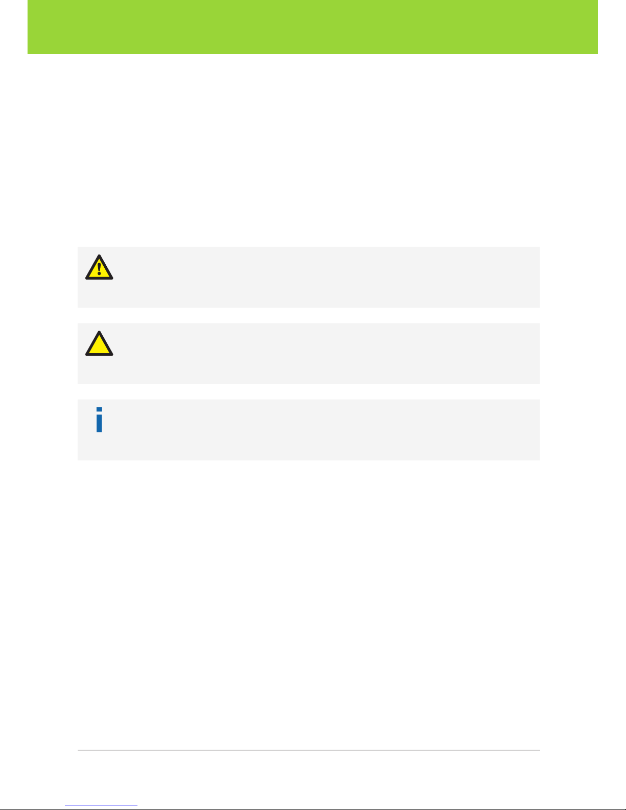
Symbols Used
This guide makes use of the following symbols and conventions:
Warning!
Indicates a situation which, if not avoided, could result in minor or moderate injury
and/or property damage or damage to the device.
Caution
Indicates a situation which, if not avoided, may result in minor damage to the
device, in malfunction of the device or in data loss.
Note
Notes provide information on special issues related to the device or provide information that will make operation of the device easier.
This headline indicates the beginning of a procedure:
1. This number indicates the first step of a certain procedure you are expected to
follow. Following steps are numbered accordingly.
f This arrow indicates an expected result of your action.
Linux commands are written in this monospaced font.
This symbol indicates a reference to a different part of this manual or to external
documents.
D2 Intelligent Cameras – User Guide6
Intelligent Components
General Information

2 Safety
The declarations of conformity (as far as available or applicable), data sheets, and operating instructions applicable to your product are an integral part of this document. Keep
these instructions for future use.
Intended Use
The device comprises an embedded PC with integrated camera. The device is designed for capturing, processing, and transmission of (image) data and analog or digital
signals.
General Safety Instructions
Installation and operation may only be carried out by trained personnel.
Faultless and safe operation of the device requires proper transport, storage, setup,
and handling.
Please refer the device to VRmagic if repairs should become necessary. Servicing is
required if the device has been damaged in any way or does not operate normally.
The camera generates heat during operation. Make sure that the camera is always
operated within the specified temperature range. If necessary, provide adequate heat
dissipation measures.
Do not subject the device to direct sunlight, wet conditions, dust, strong impacts, and
heat. Observe the ambient conditions specified in the following.
Unplug the device during lightning storms or when not in use for longer periods of time.
Do not disassemble any part of the camera, unless explicitly described in this manual.
Disassembly may cause damage and voids the product warranty.
Power Supply
Connect the device to an appropriate power supply only (5 V DC ±5%, 15W).
Ambient Conditions
Do not operate the device near a TV or radio station that radiates high powered radio-frequencies. Operating temperature: 0...40°C (32...104°F). Storage temperature:
-30...80°C (-22...176°F).
ESD Prevention
Electrostatic discharges may cause serious, permanent damage to the camera. When
working with board-level cameras, always make sure that you work in an ESD protected area according to international standards (IEC 61340-5-1 (2007-08)).
7D2 Intelligent Cameras – User Guide
Safety
Intelligent Components
3 Overview
3.1 D2 Intelligent Camera Architecture
The D2 intelligent cameras from VRmagic function as an embedded system. They are
equipped with a highly integrated DaVinciTM Dual-Core CPU from Texas Instruments,
which features a 300 MHz ARM9 processor and a 600 MHz digital signal processor
(DSP).
Ethernet
100 MBit
USB 2.0 Video Audio GPIO ...
Dual-Core Chip
Slave
DSP C64x+
Codecs
600 MHz
4800 MIPS
Master
ARM9
Linux
300 MHz
Interrupt Request
System Interconnection
200 MHz | 64 Bit
DDR2 RAM
166 MHz (DDR333)
256 MB
32 Bit
Image Sensor(s)
Fig. 1: Intelligent camera architecture (D2 platform)
The Linux OS runs on the ARM processor so that the DSP is completely available for
image processing tasks. Communication betwen ARM and DSP is controlled by the
DSPlink kernel module.
We recommend the Codec Engine framework from TI to the application developers
who wish to use both the ARM and the DSP for their applications.
D2 Intelligent Cameras – User Guide8
Intelligent Components
Overview

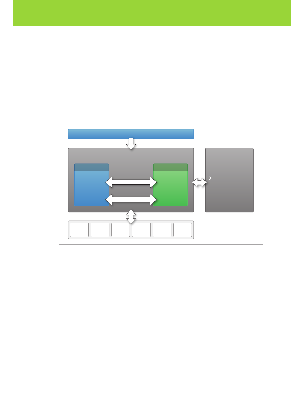
By default, the camera’s DDR2 memory is partitioned into three areas: the Linux memory, the contiguous shared memory (CMEM), and the DSP memory. Images from the
image sensor are always written to the shared memory, where they are accessible for
both the ARM and the DSP.
Shared
Memory
DSP
Memory
Linux
Memory
256 MB RAM
DSP C64+
Codecs
ARM9
Linux
Control
CMEM
Data
Data
Data
Data
virtual
addresses
physical
addresses
variable
size
Fig. 2: Interaction of dual-core CPU and memory
The default size of the memory partitions are 96 MB for the Linux memory, 96 MB for
the shared memory, and 64 MB for the DSP memory. The size of the memory areas
can be changed if necessary ( section 6.7 and section 6.8).
9D2 Intelligent Cameras – User Guide
Overview
Intelligent Components
3.2 Camera Models
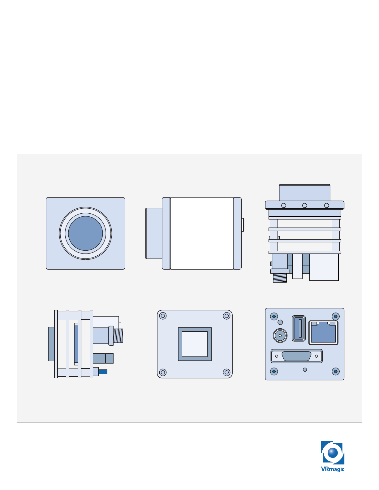
Single-Sensor Cameras VRmD(F)C-X
Single-sensor cameras are equipped with one image sensor. The sensor board is
mounted directly onto the camera base unit, thus forming one compact unit. Singlesensor cameras are available as board-level cameras (OEM versions), board-level
cameras with optics (COB versions) and as cameras with aluminium housing (PRO
versions).
All cameras are equipped with a sensor board, a CPU board, and an interface board.
Depending on the image sensor, the camera may be equipped with an additional FPGA
board (VRmDFC-X models).
Sensor
Front View Side View Back View
Fig. 3: Intelligent single-sensor camera (OEM) with standard interface board and FPGA board
1 Sensor board with image sensor
2 FPGA board (VRmDFC-X cameras only)
3 CPU board
4 Interface board
D2 Intelligent Cameras – User Guide10
Intelligent Components
Overview
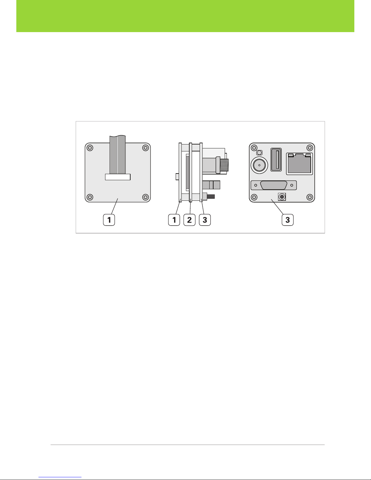
Remote-Sensor Cameras VRmDC-X-E
Remote-sensor cameras consist of a base unit and an external sensor board connected
to the base unit by flex-foil cable. Remote-sensor cameras are available as board-level
cameras (OEM versions) and board-level cameras with optics (COB versions).
The base unit consists of a sensor connection board, a CPU board, and an interface
board.
Back ViewFront View Side View
Fig. 4: Base unit of intelligent remote-sensor camera with standard interface board
1 Sensor connection board (external sensor board is connected via flex-foil cable)
2 CPU board
3 Interface board
11D2 Intelligent Cameras – User Guide
Overview
Intelligent Components
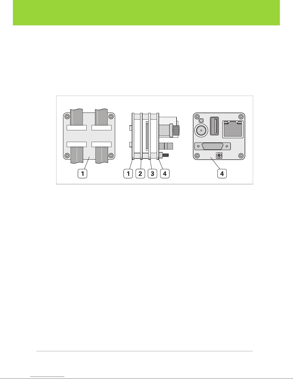
Multi-Sensor Cameras VRmDMFC
Multi-sensor cameras consist of a base unit and up to four external sensor boards connected to the base unit by flex-foil cables. They are available as board-level cameras
(OEM versions) and board-level cameras with optics (COB versions).
The base unit consists of a sensor connection board, an FPGA board, a CPU board, and
an interface board.
Back ViewFront View Side View
Fig. 5: Base unit of intelligent multi-sensor camera with standard interface board
1 Sensor connection board (external sensor boards are connected via flex-foil
cables)
2 FPGA board
3 CPU board
4 Interface board
D2 Intelligent Cameras – User Guide12
Intelligent Components
Overview
3.3 Connectors and Interfaces
All board-level cameras (OEM and COB versions) are available with two different interface boards: the standard interface board and the CUEO1 pico interface board. PRO
cameras in aluminium housing are available only with the standard interface board.
• Standard interface board: This board is equipped with standard connectors, for
example an RJ45 receptacle for the Ethernet connection.
• CUEO1 pico interface board: All interfaces are available on miniature connectors
(Molex PicoBlade), thus reducing board size and weight. This board allows for
cost-effective and flexible connections.
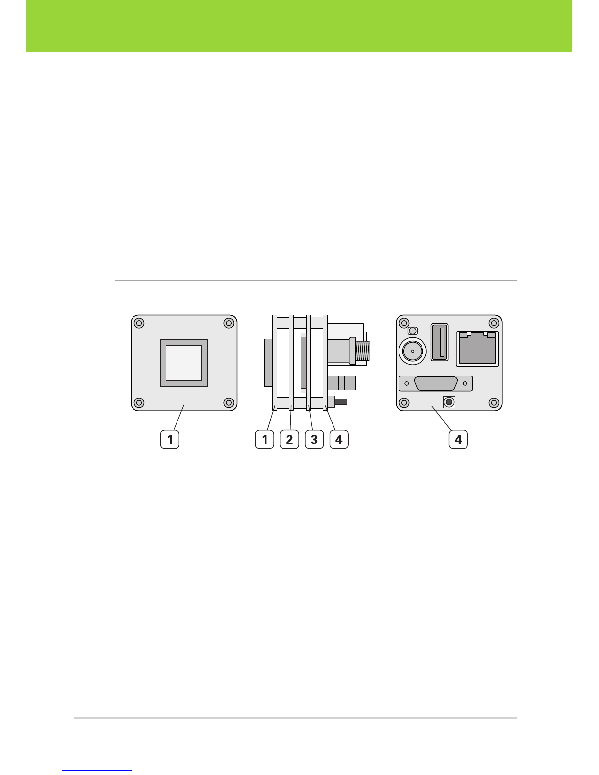
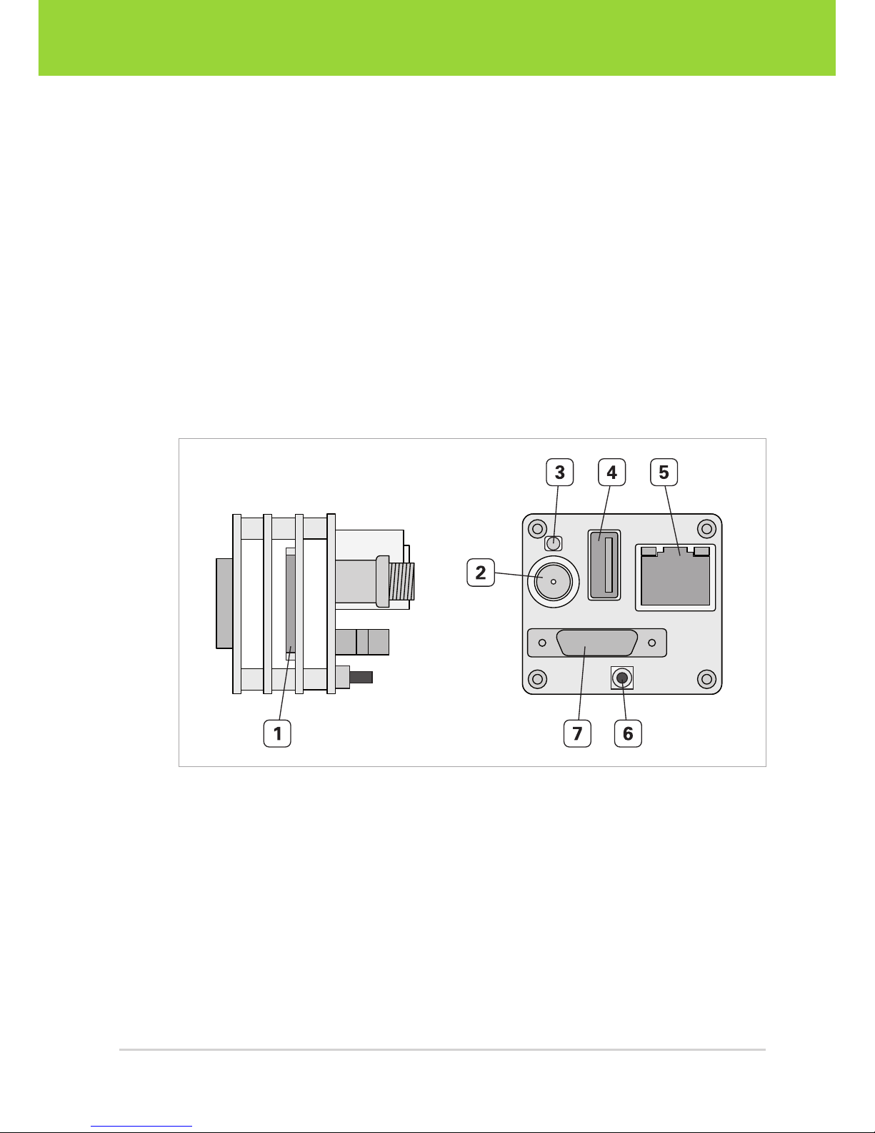
All board-level cameras (OEM and COB versions) feature a lateral DF14-15P connector
for serial console and JTAG located on the CPU board. This connector is not accessible
in housing cameras (PRO versions).
Fig. 6: OEM camera with standard interface board
1 DF14-15P connector for serial console and JTAG on CPU board
2 Power inlet (+5 V DC, ±5%)
3 Red status LED
4 USB host connector
5 RJ45 Ethernet connector
6 Power button
7 MPE Garry Micro T connector for trigger, strobe, RS232, S-Video, GPIOs
13D2 Intelligent Cameras – User Guide
Overview
Intelligent Components
SPI
GPIO
USB
RGB
PWR
UARTETH
BTN
TRG
VGA
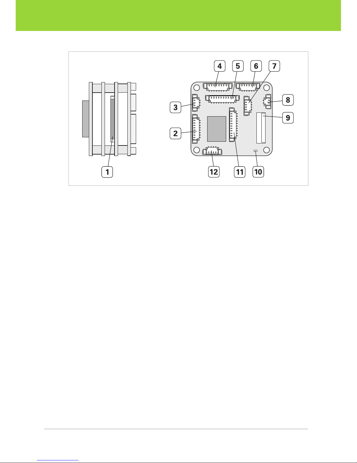
Fig. 7: OEM camera with CUEO1 pico interface board
1 DF14-15P connector for serial console and JTAG on CPU board
2 Ethernet
3 Serial port (UART)
4 SPI port
5 General porpose I/Os
6 Power inlet (+5 V DC, ±5%)
7 Trigger and strobe
8 Power button
9 RGB888 interface for connection of external HDMI output board
10 Green status LED
11 Analog video output (Composite or S -Video)
12 USB host connector
D2 Intelligent Cameras – User Guide14
Intelligent Components
Overview

3.4 Accessories
There are optional accessory kits for the D2 intelligent cameras containing adapters,
cables, power supply and a USB update flash drive.
VRmDC Accessory Kit 2.0
For cameras with standard interface board
1 VRmDC-2 service cable
1 VRmDC-X adapter cable
1 AC Adapter 5 V/15 W Worldwide
1 Null modem cable 3 m
1 USB-serial adapter 9-pin
1 USB update flash drive
1 S-Video cable
VRmDC Accessory Kit PICO
For cameras with pico interface board
VRmDC Accessory Kit PICO2
For cameras with pico interface board
1 VRmDC-2 service cable
1 AC Adapter 5 V/15 W Worldwide
1 Null modem cable 3 m
1 USB-serial adapter 9-pin
1 USB update flash drive
1 Picoblade-open end 2 pin
1 Picoblade-open end 3 pin
2 Picoblade-open end 4 pin
1 Picoblade-open end 6 pin
2 Picoblade-open end 8 pin
2 Picoblade-open end 10pin
1 VRmDC-2 service cable
1 AC Adapter 5 V/15 W Worldwide
1 Null modem cable 3 m
1 USB-serial adapter 9-pin
1 USB update flash drive
1 Picoblade-open end 2 pin
1 Picoblade-open end 3 pin
1 Picoblade-open end 4 pin
1 Picoblade-open end 8 pin
2 Picoblade-open end 10pin
1 Ethernet Adapter Cable VRmCUEO1
1 Ethernet Adapter Panel (RJ45)
1 USB-A Adapter Cable VRmCUEO1
1 Power Cable VRmCUEO1
15D2 Intelligent Cameras – User Guide
Overview
Intelligent Components

4 Software Installation
4.1 Downloading the VRmagic Software
Downloading the software package:
1. Visit www.vrmagic.com/imaging/downloads/ .
2. Scroll down to D2 Intelligent Camera Platform.
3. Download the .zip file VRmUsbCam Distribution for Developers and keep it for
future use.
4.2 Installing the D2 Camera SDK
VRmagic D2 Camera SDK
The D2 SDK is required to develop camera applications on your host PC that will be
executed on the D2. To do so, you need to additionally set up and configure crosscompile tool chain on your host PC as described in chapter 7.
Installing the VRmagic D2 Camera SDK:
1. To install the SDK, unzip the file you downloaded in the previous section.
f The following directories were created on your hard drive.
D2 Intelligent Cameras – User Guide16
Intelligent Components
Software Installation

Directory structure of the D2 SDK distribution (excerpt)
D2
development_kit VRmUsbCam DevKit for D2
demos Examples for the API usage
docs Documentation of the VRmagic camera API
include VRmagic API include files
lib VRmagic API development library
toolchains Manuals and software regarding ARM and DSP
Cross-Compilers
vm_lib VRmagic machine vision library
wrappers C++ wrapper
docs Additional documentation (cable plans and pinouts)
drivers Windows driver for the USB-serial adapter,
Windows driver for accessing ext2 partitions
firmware Binary images of the camera’s firmware (bootloader,
kernel and rootfs)
src
kernel Linux kernel sources
rootfs tar archive of the camera’s root filesystem
linux VRmUsbCam DevKit for Linux host PC (x86)
windows VRmUsbCam DevKit for Windows host PC (x86)
17D2 Intelligent Cameras – User Guide
Software Installation
Intelligent Components

4.3 Installing the Camera Runtime and the Host
SDK
VRmagic Windows/Linux PC SDK
The host PC SDK is required to develop camera applications that will be executed on
the host PC. Thus, this SDK is not required for compiling camera applications that will
be executed directly on the D2. However, the host SDK is useful to debug your camera
application on the host PC first and cross-compile it for the D2 later.
VRmagic Windows/Linux PC Camera Runtime and CamLab Application
The camera runtime enables the Linux host PC to access VRmagic cameras, for example using the VRmagic CamLab application. CamLab enables you to find, test and
configure all VRmagic cameras available on the Ethernet.
Note
The included SDK, the runtime libraries for the host PC, and the cross-compile toolchain for ARM by Mentor Graphics are built for the x86/i386 architecture (32bit).
In order to install them on a 64 bit machine, you have to make sure that your operating system supports the installation of 32 bit applications. Windows supports this
by default. On 64 bit Linux machines the support for 32 bit applications needs to
be activated by the user. Please consult the documentation of your Linux distribution for more information.
Installing the camera runtime and SDK for Windows:
1. Navigate to the windows directory in the downloaded and unzipped SDK
distribution.
2. Unpack the zip file VRmUsbCam DevKit for Windows (x86)*.zip.
3. To install the SDK, run setup.exe from the directory you unzipped in step 2.
4. Follow the on-screen instructions.
f A message is displayed after successful installation. A new folder VRmagic
was created in your Windows start menu.
D2 Intelligent Cameras – User Guide18
Intelligent Components
Software Installation

Installing the camera runtime and SDK for Linux:
1. Navigate to the linux directory in the downloaded and unzipped SDK distribution.
2. Navigate to the x86 subdirectory.
3. To install the runtime libraries and the CamLab application, execute
sudo dpkg -i vrmagic-linux-pc-camera-runtime-*.deb .
4. To install the host PC SDK, execute
sudo dpkg -i vrmagic-linux-pc-camera-sdk-*.deb .
5. For further information read the README file in the directory
/opt/vrmagic/sdk-*/x86/development_kit.
4.4 Installing the USB to RS232 Driver
Note
You will only need the USB to RS232 adapter driver if you have a board level camera (OEM or COB) and a Windows computer that does not have a serial port.
The driver for Linux is already included in the kernel main line (pl2303), so your
Linux distribution should work with the USB to RS232 adapter out of the box.
Installing the USB to RS232 adapter driver:
1. Navigate to the D2/drivers/usb_to_rs232_adapter directory in the downloaded
SDK distribution.
2. Unpack the file USB_to_Serial_cable.zip.
3. To install the driver, run the included .exe file and follow the on-screen
instructions.
19D2 Intelligent Cameras – User Guide
Software Installation
Intelligent Components

4.5 Installing a Console Application
We recommend installing PuTTY for Windows computers. PuTTY is an open-source
SSH, Telnet, and serial client. The standard Windows console does not support SSH,
which is necessary to access the camera.
Note
Linux users can use the Linux terminal to access the camera using SSH. However,
we also recommend using PuTTY under Linux, because it is more convenient.
Downloading and running PuTTY (Windows):
1. Visit http://www.putty.org/ .
2. Download putty.exe.
3. No installation is necessary. Simply run putty.exe to use the console.
Downloading and running PuTTY (Ubuntu Linux):
1. Install PuTTY by executing
sudo apt-get install putty in the terminal.
2. To run PuTTY, execute
sudo putty .
D2 Intelligent Cameras – User Guide20
Intelligent Components
Software Installation
5 Hardware Installation
5.1 Connecting External Sensor Boards
Note
This section only applies to remote-sensor cameras and multi-sensor cameras.
Caution
Possible malfunction of camera
Observe the correct orientation of the flex-foil cable contacts as indicated in the
instructions and the drawings. Otherwise the device will not function.
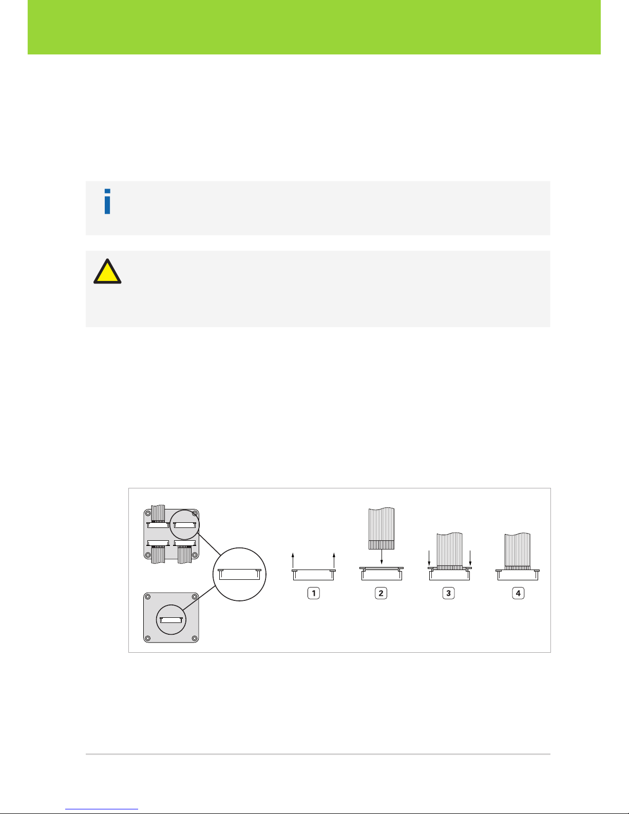
Connecting the flex-foil cable(s) to the base unit:
1. Pull out the lock of the connector on the base unit ( Fig. 8 on page21).
2. Insert the flex-foil cable with the blue marker facing the board and the open con-
tacts facing you.
3. Secure the cable by pushing the lock back in.
4. Repeat steps 1 to 3 for further external sensor boards.
Multi-Sensor Base Unit
Remote-Sensor Base Unit
Fig. 8: Connecting the flex-foil cable to the base unit: contacts visible, blue marker not visible
21D2 Intelligent Cameras – User Guide
Hardware Installation
Intelligent Components
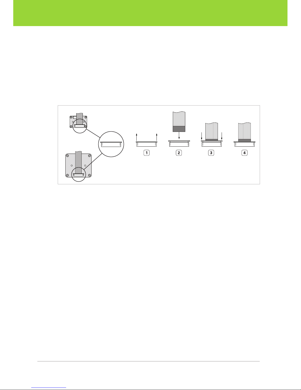
Connecting the flex-foil cable(s) to the sensor board(s):
1. Pull out the lock of the connector on the sensor board ( Fig. 9 on page22).
2. Insert the flex-foil cable with the blue marker facing you and the open contacts
facing towards the sensor board.
3. Secure the cable by pushing the lock back in.
4. Repeat steps 1 to 3 for further external sensor boards.
VRmMS-12
VRmS-9/12/14/16/18
Fig. 9: Connecting the flex-foil cable to the sensor board: contacts not visible, blue marker visible
D2 Intelligent Cameras – User Guide22
Intelligent Components
Hardware Installation
5.2 Connecting an External HDMI Board
Note
This section only applies to cameras equipped with the pico interface board
VRmCUEO1 and an optional external HDMI output board.
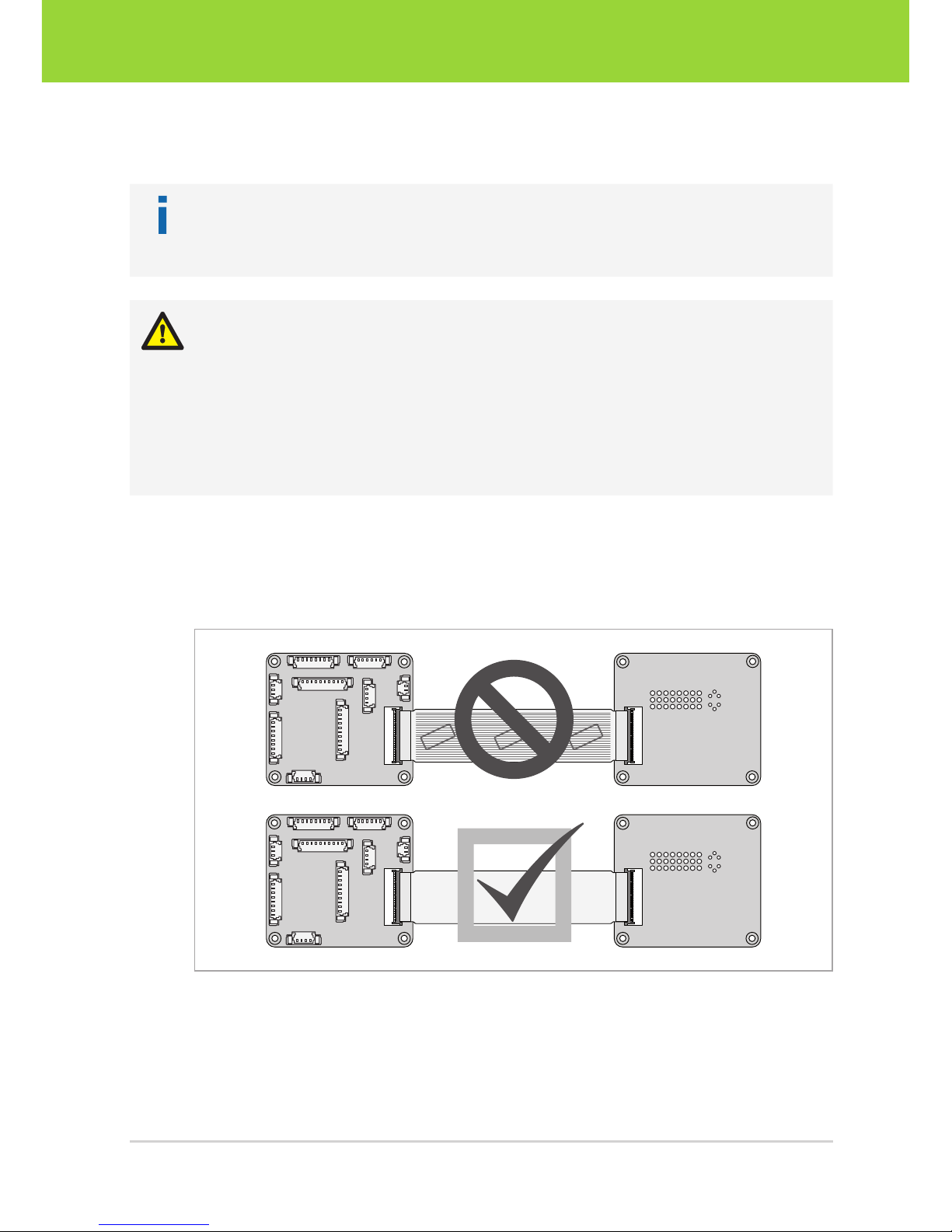
Warning!
Possible destruction of equipment
The camera stack and the HDMI board will be damaged should the FPC cable be
inserted with the wrong orientation while the camera is connected to power!
Observe the correct orientation of the FPC cable contacts. The visible electrical contacts and the label of the cable have to face the boards ( Fig. 10 on
page23).
The VRmCUEO1 pico interface board is equipped with an RGB888 interface via a 45 pin flexible printed circuit connector ( Fig. 7 on page 14). Use this interface to
attach the VRmagic HDMI output board to the intelligent camera. An FPC cable is
supplied.
LABEL
LABEL
LABEL
Fig. 10: Correct orientation of the flex-foil cable
23D2 Intelligent Cameras – User Guide
Hardware Installation
Intelligent Components
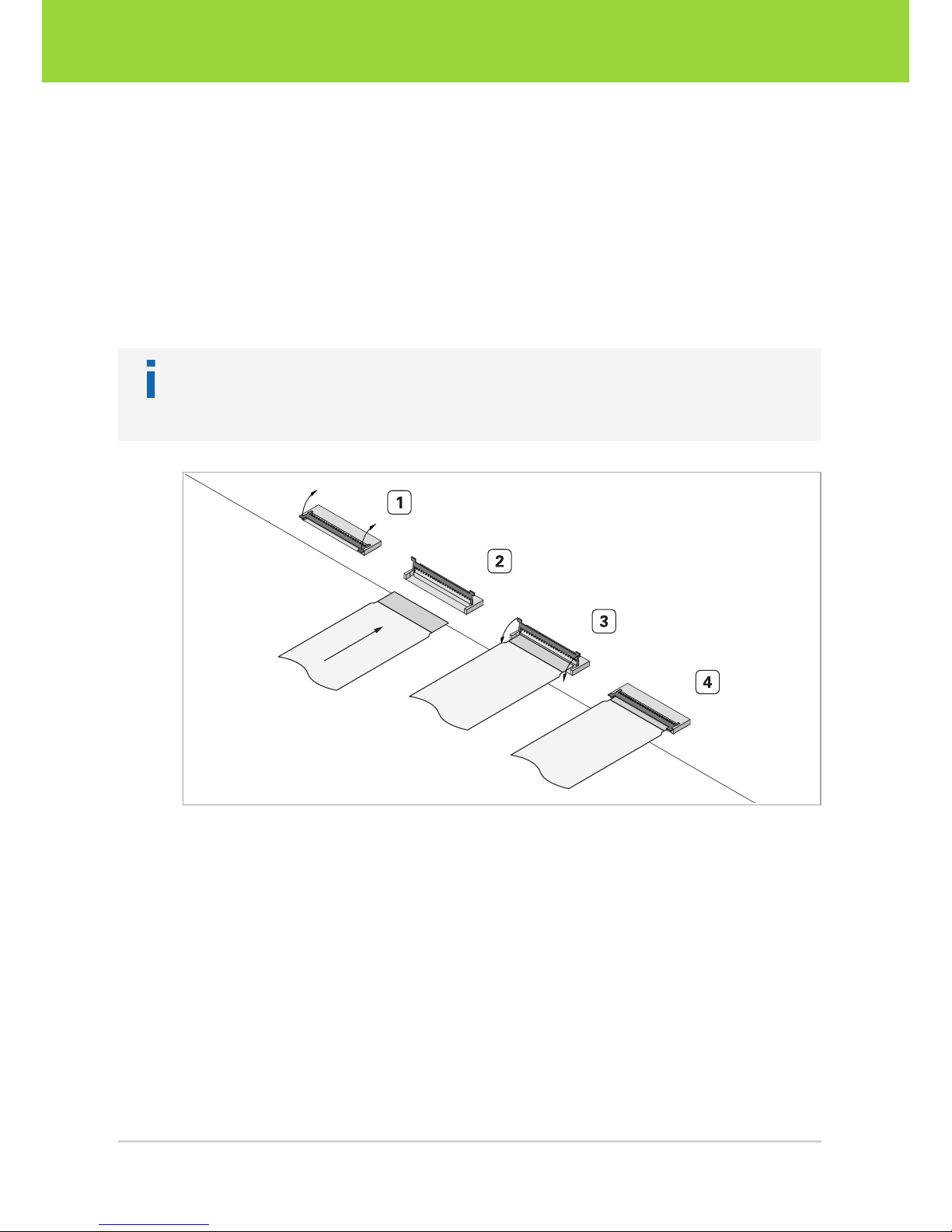
Connecting an external HDMI board:
1. Open the lock of the FPC connector on the camera interface board by flipping it
upwards ( Fig. 11 on page24).
2. Insert the FPC cable observing the correct orientation. The visible electrical con-
tacts and the label have to face the board (Fig. 10 on page23).
3. Secure the cable by pushing the lock down.
4. Proceed the same way to connect the cable to the HDMI board.
Note
The boot parameters of the camera have to be changed in order to make use of the
HDMI board. A detailed description is provided in section 6.8.
Fig. 11: Attaching the FPC cable to the FPC connector
D2 Intelligent Cameras – User Guide24
Intelligent Components
Hardware Installation
 Loading...