

Page 1
VRmagic
USB Camera
User Guide
Issued July 2014
Page 2

USB Cameras – User Guide
Document version: 1.3
Date of issue: July 16, 2014
Applicable to: all USB cameras, SDK release ≥ 4.0
Subject to change without notice. Errors excepted.
This document is protected by copyright. All rights reserved. No part of this
document may be reproduced or transmitted for any purpose in any form
or by any means, electronically or mechanically, without expressly written
permission by VRmagic.
Windows
®
is a registered trademark of Microsoft®.
VRmagic GmbH
Augustaanlage 32
68165 Mannheim
Germany
Phone +49 (0)621 400 416-20
Fax +49 (0)621 400 416-99
[email protected]
www.vrmagic-imaging.com
Page 3

Page 4

Table of Contents
1 General Information ..........................................................6
2 Overview .............................................................................7
2.1 Camera Models ...........................................................................................7
2.2 Connectors and Interfaces ........................................................................ 10
2.3 Accessories ............................................................................................... 13
3 Software Installation ......................................................14
3.1 Downloading the SDK ............................................................................... 14
3.2 Installing the SDK ...................................................................................... 14
3.3 Contents of the SDK .................................................................................. 15
3.3.1 Windows ....................................................................................... 15
3.3.2 Linux ..............................................................................................16
4 Hardware Installation ......................................................17
4.1 Connecting External Sensor Boards ......................................................... 17
4.2 Connecting the Interface Cables ............................................................... 19
4.2.1 General Information on the USB Connection ............................... 19
4.2.2 Cameras with Hirose DF14-15P Connector ..................................20
4.2.3 Cameras with MPE Garry Micro-T Connector ..............................22
4.2.4 Compact Single-Sensor Cameras ................................................23
4.3 Connecting to Power .................................................................................23
4.3.1 Power Supply via USB .................................................................. 24
4.3.2 External Power Supply .................................................................25
5 First Steps ........................................................................26
5.1 Auto-Detection of the Camera ..................................................................26
5.2 Starting CamLab ........................................................................................ 26
5.3 Accessing the Demo Applications ............................................................28
5.4 Using Trigger and Strobe ........................................................................... 29
5.4.1 Trigger Input ..................................................................................30
5.4.2 Strobe Output ...............................................................................31
USB Cameras – User Guide4
USB Components
Table of Contents
Page 5

6 Firmware Update .............................................................32
7 Appendix .......................................................................... 34
7.1 Cable Plan VRmC-X OEM Interface Cable ................................................ 34
7.2 Cable Plan VRmDC/FC-X-DF14- Open.......................................................35
7.3 Cable Plan VRmC-X PRO Interface Cable .................................................36
7.4 Pinout 4-pin Header VRmC-X+ OEM/COB ............................................... 37
7.5 Status LED Indications ..............................................................................38
8 Index ..................................................................................39
5USB Cameras – User Guide
Table of Contents
USB Components
Page 6
1 General Information
This guide applies to all USB cameras from VRmagic. Follow this guide chapter by
chapter to set up and understand your device. If a section of this document only applies
to certain camera models, this is indicated at the beginning of the respective section.
Symbols Used
This guide makes use of the following symbols and conventions:
Warning!
Indicates a situation which, if not avoided, could result in minor or moderate injury
and/or property damage or damage to the device.
Caution
Indicates a situation which, if not avoided, may result in minor damage to the
device, in malfunction of the device or in data loss.
Note
Notes provide information on special issues related to the device or provide information that will make operation of the device easier.
This headline indicates the beginning of a procedure:
1. This number indicates the first step of a certain procedure you are expected to
follow. Following steps are numbered accordingly.
f This arrow indicates an expected result of your action.
This symbol indicates a reference to a different part of this manual or to external
documents.
USB Cameras – User Guide6
USB Components
General Information
Page 7
2 Overview
2.1 Camera Models
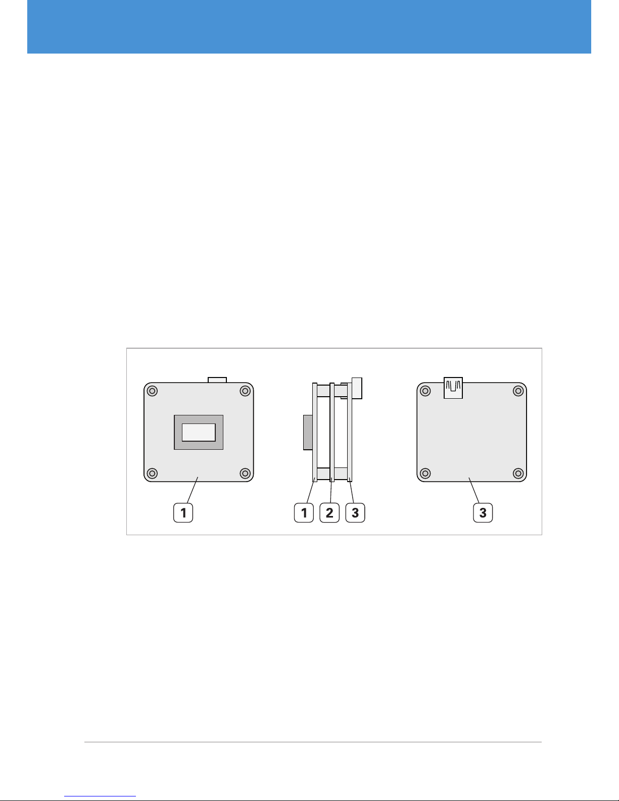
Single-Sensor Cameras VRm(F)C-X
Single-sensor cameras are equipped with one image sensor. The sensor board is
mounted directly onto the camera base unit, thus forming one compact unit. Singlesensor cameras are available as board-level cameras (OEM versions), board-level
cameras with optics (COB versions) and as cameras with aluminium housing (PRO
versions).
All cameras are equipped with a sensor board and an interface board. Depending on
the image sensor, the camera may be equipped with an additional FPGA board (VRmFC-X models).
Front View Side View Back View
Sensor
Fig. 1: USB single-sensor camera (OEM) with FPGA board
1 Sensor board with image sensor
2 FPGA board (VRmFC-X cameras only)
3 Interface board
7USB Cameras – User Guide
Overview
USB Components
Page 8
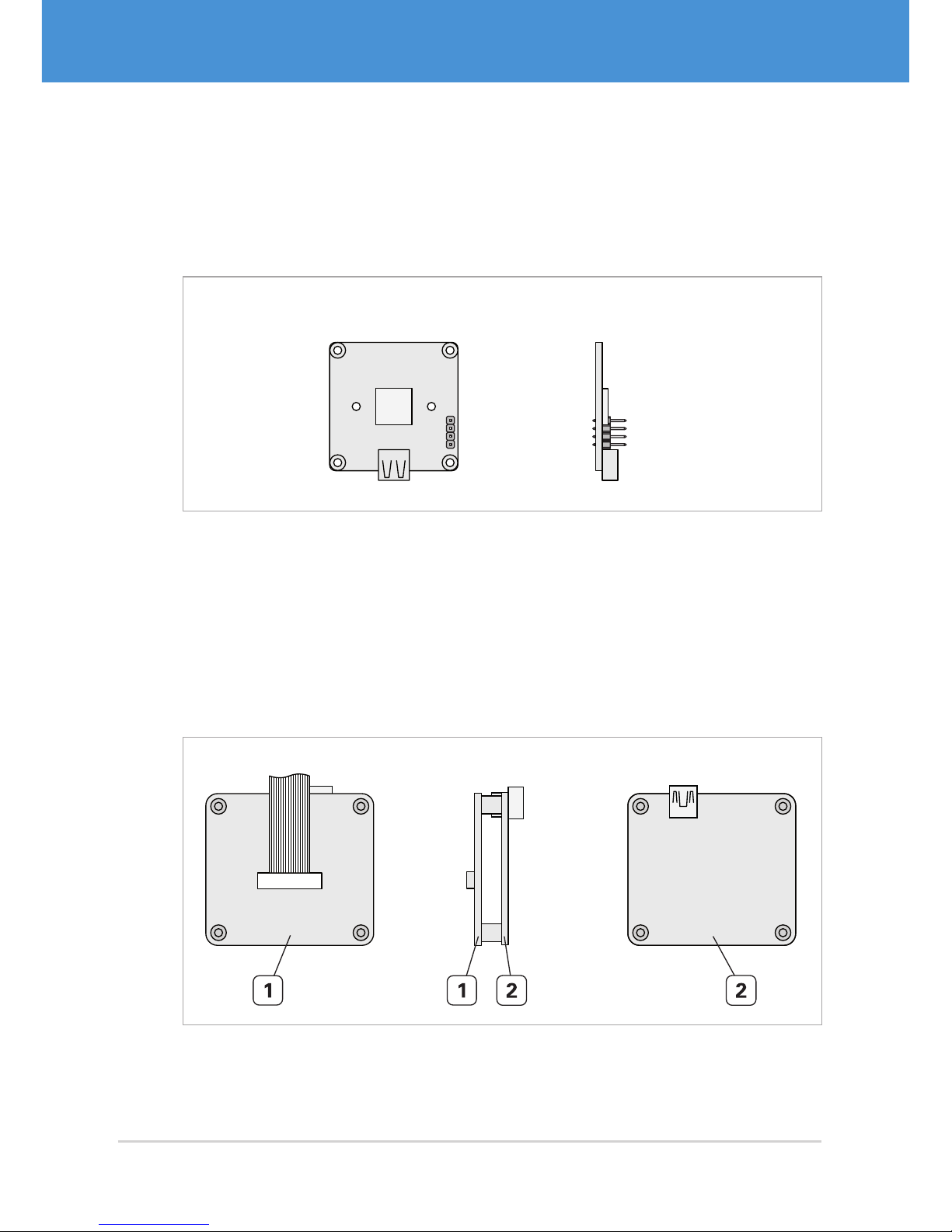
Compact Single-Sensor Cameras VRmC-X+
Compact single-sensor cameras consist of one board only, making them very small.
They are equipped with one image sensor and are available as board-level cameras
(OEM versions), board-level cameras with optics (COB versions) and as cameras with
aluminium housing (PRO versions).
Front View Side View
USB
Sensor
T
G
G
S
Fig. 2: Compact USB single-sensor camera (OEM)
Remote-Sensor Cameras VRmC-X-E
Remote-sensor cameras consist of a base unit and an external sensor board connected
to the base unit by flex-foil cable. Remote-sensor cameras are available as board-level
cameras (OEM versions) and board-level cameras with optics (COB versions).
The base unit consists of a sensor connection board and an interface board.
Back ViewFront View Side View
Fig. 3: Base unit of USB remote -sensor camera
1 Sensor connection board (external sensor board is connected via flex-foil cable)
2 Interface board
USB Cameras – User Guide8
USB Components
Overview
Page 9
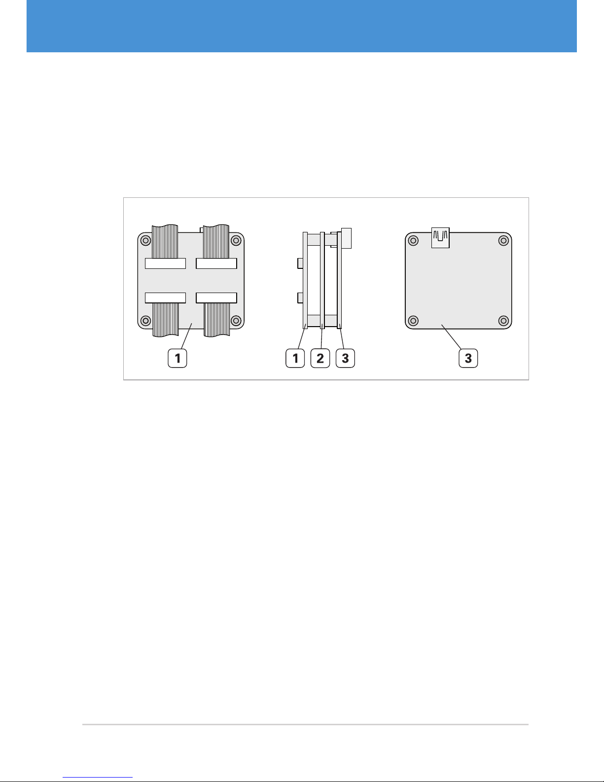
Multi-Sensor Cameras VRmMFC
Multi-sensor cameras consist of a base unit and up to four external sensor boards connected to the base unit by flex-foil cables. They are available as board-level cameras
(OEM versions) and board-level cameras with optics (COB versions).
The base unit consists of a sensor connection board, an FPGA board, and an interface
board.
Front View Side View Back View
Fig. 4: Base unit of USB multi-sensor camera with standard interface board
1 Sensor connection board (external sensor boards are connected via flex-foil
cables)
2 FPGA board
3 Interface board
9USB Cameras – User Guide
Overview
USB Components
Page 10
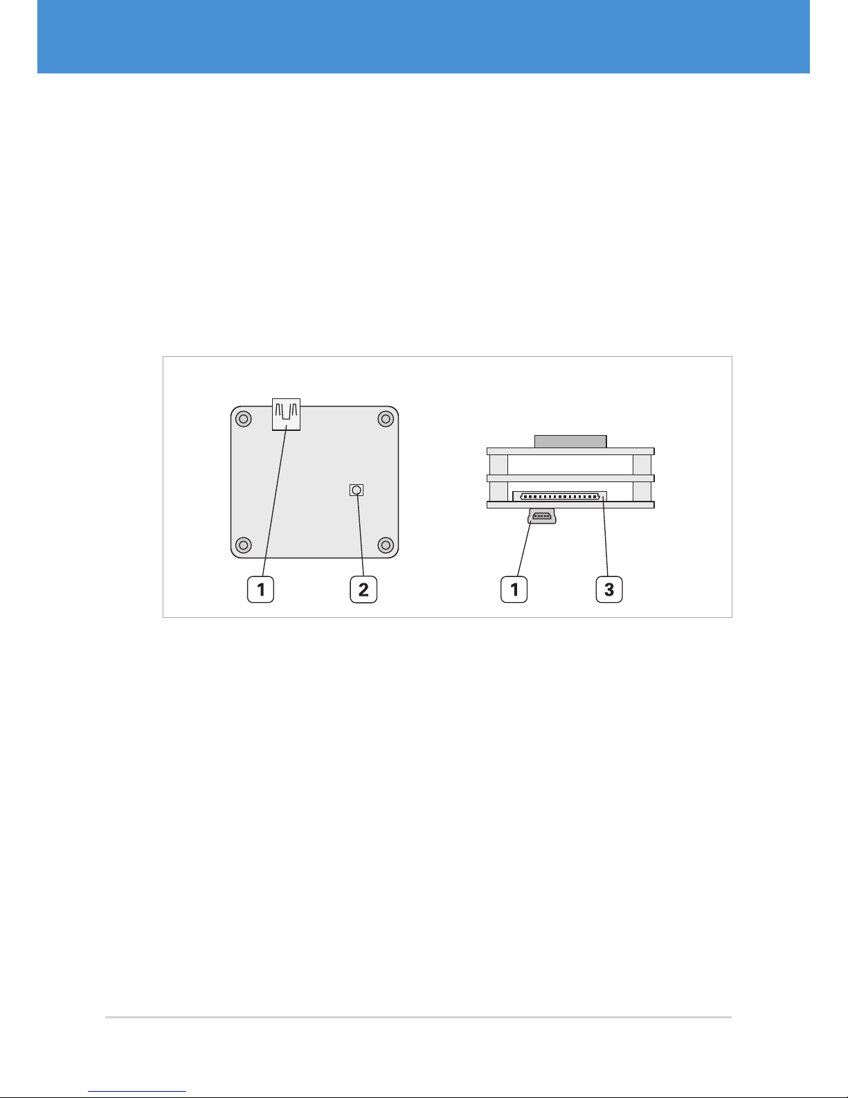
2.2 Connectors and Interfaces
Depending on your camera model, the available interfaces vary in type and position.
There are basically three different interface configurations, which are described in the
following.
Single-/Remote-/Multi-Sensor Cameras OEM and COB
Single-sensor cameras, remote-sensor cameras, and multi-sensor cameras in OEM
and COB versions are equipped with a USB connector, a Hirose DF14-15P connector
for trigger/strobe and external power supply, and a status LED ( Fig. 5 on page10).
Back View Top View
Fig. 5: Interfaces of a single-sensor camera VRmFC-X OEM
1 USB Mini-B port
2 Status LED
3 DF14-15P connector for trigger, strobe, and external power supply
USB Cameras – User Guide10
USB Components
Overview
Page 11
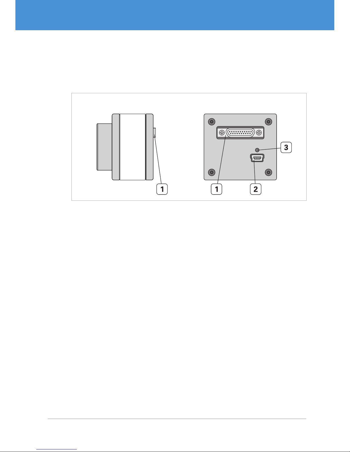
Single-Sensor Cameras PRO
Single-sensor cameras in PRO version are equipped with a USB connector, an MPE
Garry Micro-T connector for trigger/strobe and external power supply, and a status LED
( Fig. 6 on page11).
Side View Back View
Fig. 6: Interfaces of a single-sensor camera VRmC-X PRO
1 MPE Garry Micro-T 386-2-021-ZS0 connector for trigger, strobe, and external
power supply
2 USB Mini-B port
3 Status LED
11USB Cameras – User Guide
Overview
USB Components
Page 12
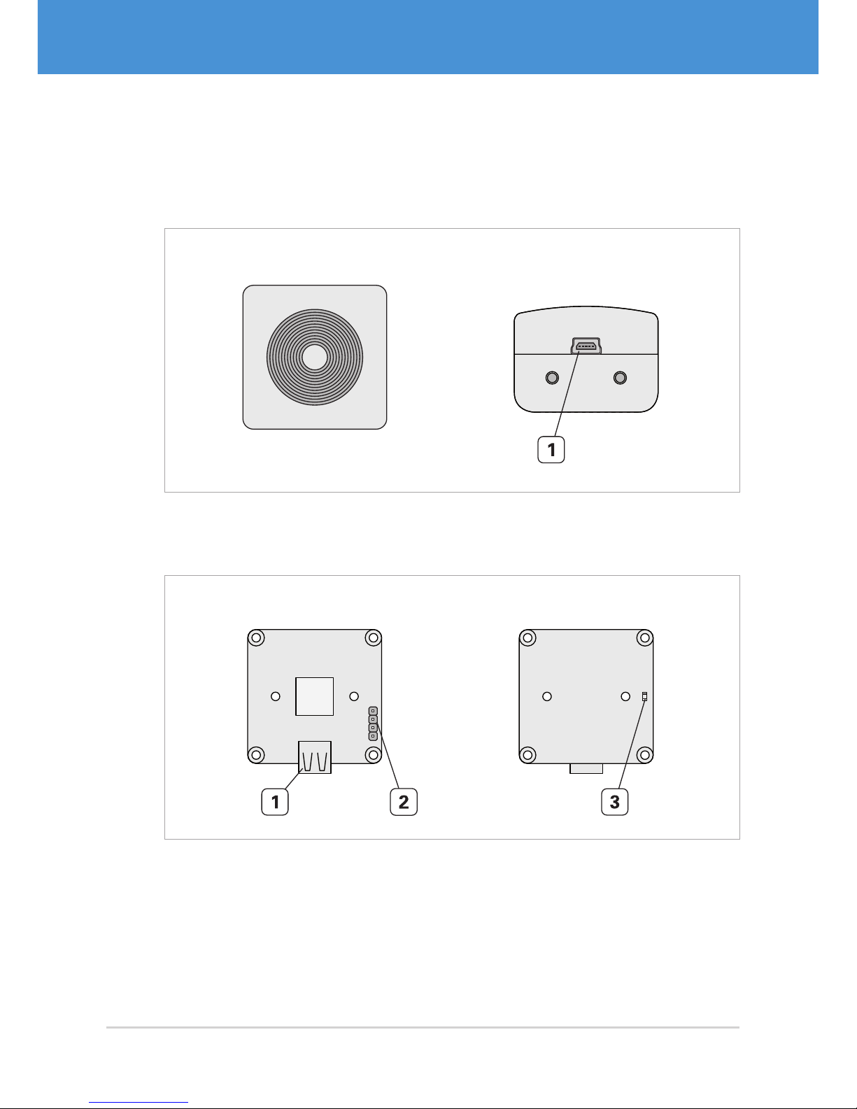
Compact Single-Sensor Cameras
Compact single-sensor cameras: PRO variants are equipped with a USB connector
(Fig. 7 on page 12). OEM and COB variants also feature an additional 4-pin header
for trigger/strobe and a status LED ( Fig. 7 on page12).
Front View Top View
Fig. 7: Interfaces of a compact single-sensor camera VRmC-X+ PRO
1 USB Mini-B port
Side View Back View
USB
Sensor
T
G
G
S
Fig. 8: Interfaces of a compact single -sensor camera VRmC-X+ OEM
1 USB Mini-B port
2 4-pin header for trigger and strobe
3 Status LED
USB Cameras – User Guide12
USB Components
Overview
Page 13

2.3 Accessories
Accessory Description
VRmDC/FC-X-DF14-Open Interface cable with Hirose DF14 plug
on one end and open wires at the other
end ( Fig. 13 on page21).
For all board-level cameras (OEM and
COB) except compact single-sensor
cameras.
VRmC-X OEM Interface Cable Interface cable with Hirose DF14 plug
on one end and different adapters on
the other end ( Fig. 12 on page21).
For all board-level cameras (OEM and
COB) except compact single-sensor
cameras.
VRmC-X PRO Interface Cable Interface cable with MPE Garry
Micro-T plug on one end and different adapters on the other end
( Fig. 14 on page22).
For all housing cameras (PRO) except
compact single-sensor cameras.
1 Power supply 5 V / 15 W worldwide Power supply for all cameras except
compact single-sensor cameras.
13USB Cameras – User Guide
Overview
USB Components
Page 14

3 Software Installation
3.1 Downloading the SDK
Downloading the software package:
1. Visit www.vrmagic.com/imaging/downloads/ .
f The software for USB cameras can be found beneath the heading “Software
for USB Components”.
2. Dependent upon on the operating system of the target system (Linux or Win-
dows, 32 bit or 64 bit), download the .zip file VRmUsbCam DevKit for Windows
... or the .tar.bz2 file VRmUsbCam DevKit for Linux ... .
3. Unpack the downloaded file.
3.2 Installing the SDK
Note
You may install both the 32 bit version (X86) and the 64 bit version (X64) of the
SDK in parallel, if required.
Installing the software development kit (Windows):
1. Navigate into the directory created after unpacking the downloaded file.
2. To install the SDK, run setup.exe.
3. Follow the on-screen instructions.
f After successful installation a message is displayed. A new folder VRmagic
was created in your Windows start menu. Several folders were created on your
hard drive ( 3.3.1 on page 15).
Installing the software development kit (Linux):
1. Navigate into the directory created after unpacking the downloaded file.
2. To install the SDK, execute
./VRmUsbCamDevKitForLinuxX**-install as
root (**= 64 or 86). For further information, refer to the README file in the same
directory. Several folders were created on your hard drive ( 3.3.2 on page 16).
USB Cameras – User Guide14
USB Components
Software Installation
Page 15

3.3 Contents of the SDK
3.3.1 Windows
The SDK installation will create the following directories on your PC. Drive letters and
paths may vary depending on your system and installation instructions.
32 bit: C:\Program Files (x86)\VRmagic\
64 bit: C:\Program Files\VRmagic\
USB driver VRmagic USB driver installation files
VRmUsbCam VRmUsbCam and tools
CamLab Camera application with control and viewer window
CamServer Camera application for Ethernet transmission
Install Install scripts for COM API & DirectShow, Ethernet
PnP enable script
weblinks Links to VRmagic website
32 bit: C:\Program Files (x86)\Common Files\VRmagic\VRmUsbCamSDK \
64 bit: C:\Program Files (x86)\Common Files\VRmagic\VRmUsbCamSDK \
demos Demo applications
docs Product documentation
include Include file for using the shared library
lib Shared library
vm_lib Library for image processing
vsprops Property Sheets for Visual Studio (C++)
wrappers C++ and .NET wrappers
15USB Cameras – User Guide
Software Installation
USB Components
Page 16

3.3.2 Linux
Directory structure of the SDK distribution (Linux)
camlab Camera application with control and viewer window
vrmcamserver Camera application for Ethernet transmission
demos Demo applications
deviceinfo Demo application displaying device information
restorefactory
defaults
Demo application that restores all factory defaults
sdlviewer Demo application displaying the camera pictures in an
SDL widget
docs vrmusbcam API documentation
include Include file for using the shared library
lib Shared library
share
fpgaprogramfiles
setup Setup scripts, hotplug helper and ethernet enable/
disalbe scripts
udev udev rules file which invokes the hotplug helper
etc Potential contents of /etc/vrmagic
USB Cameras – User Guide16
USB Components
Software Installation
Page 17
4 Hardware Installation
4.1 Connecting External Sensor Boards
Note
This section only applies to remote-sensor cameras and multi-sensor cameras.
Caution
Possible malfunction of camera
Observe the correct orientation of the flex-foil cable contacts as indicated in the
instructions and the drawings. Otherwise the device will not function.
Connecting the flex-foil cable(s) to the base unit:
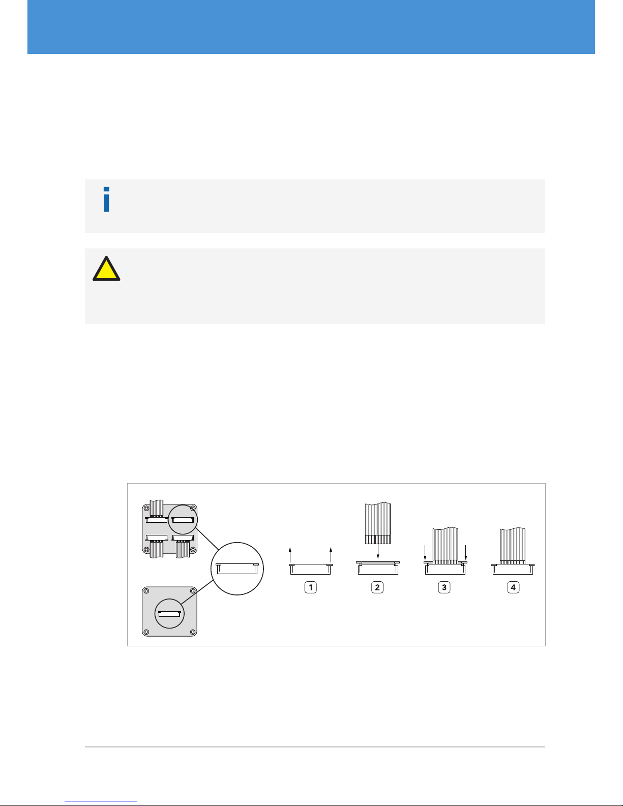
1. Pull out the lock of the connector on the base unit ( Fig. 9 on page17).
2. Insert the flex-foil cable with the blue marker facing the board and the open con-
tacts facing you.
3. Secure the cable by pushing the lock back in.
4. Repeat steps 1 to 3 for further external sensor boards.
Multi-Sensor Base Unit
Remote-Sensor Base Unit
Fig. 9: Connecting the flex-foil cable to the base unit: contacts visible, blue marker not visible
17USB Cameras – User Guide
Hardware Installation
USB Components
Page 18
Connecting the flex-foil cable(s) to the sensor board(s):
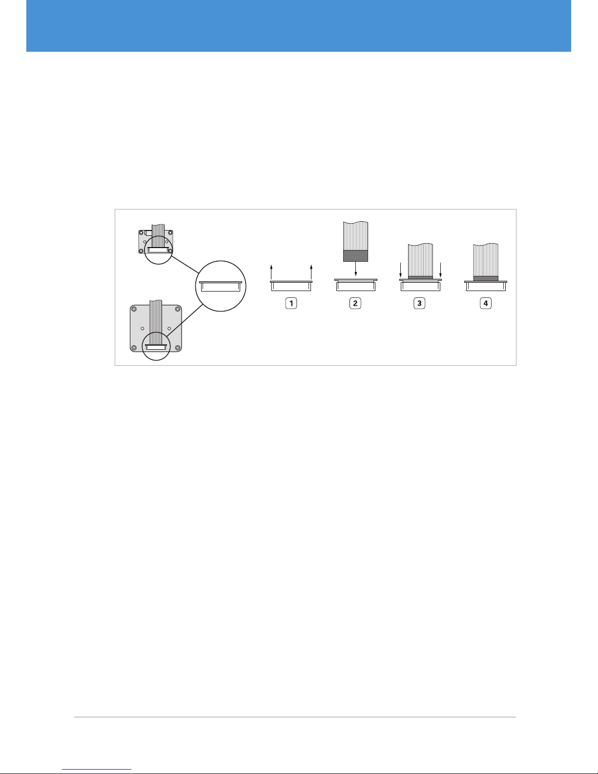
1. Pull out the lock of the connector on the sensor board ( Fig. 10 on page18).
2. Insert the flex-foil cable with the blue marker facing you and the open contacts
facing towards the sensor board.
3. Secure the cable by pushing the lock back in.
4. Repeat steps 1 to 3 for further external sensor boards.
VRmMS-12
VRmS-9/12/14/16/18
Fig. 10: Connecting the flex-foil cable to the sensor board: contacts not visible, blue marker
visible
USB Cameras – User Guide18
USB Components
Hardware Installation
Page 19
4.2 Connecting the Interface Cables
4. 2 .1 General Information on the USB Connection
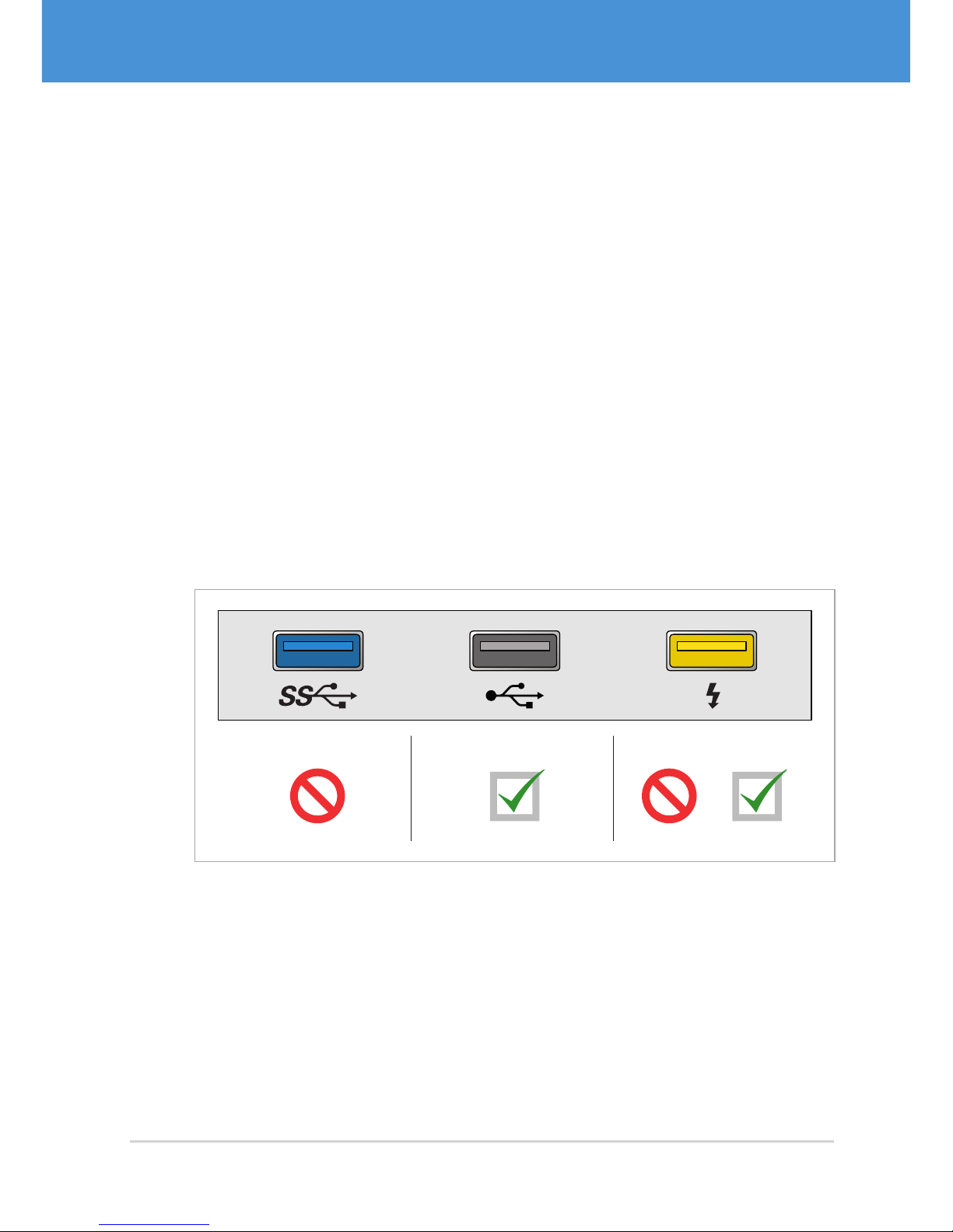
VRmagic USB cameras are not compatible with USB 3.0 hosts. Always connect the
camera to a USB 2.0 host, otherwise is will not work properly.
Although there is no standard for the labeling or the color of USB ports, most manufacturers make use of the following color codes ( Fig. 11 on page 19). Also pay
attention to possible labels or text next to USB connectors.
• Blue USB port: This is a USB 3.0 connector. Some USB 3.0 ports are additionally
labelled with a USB 3.0 logo. Do not connect the camera to USB 3.0 ports.
• Black USB port: This is a USB 2.0 connector. Some USB 2.0 ports are additionally
labelled with a USB 2.0 logo.
• Yellow USB port: This type of connector permanently supplies power to the connected device, even if the host is switched off. Yellow USB ports may be USB 2.0
or USB 3.0 connectors. Pay attention to the label in order to find out.
USB 2.0
USB 2.0
USB 3.0 USB 3.0
Fig. 11: USB port colors
19USB Cameras – User Guide
Hardware Installation
USB Components
Page 20

4.2.2 Cameras with Hirose DF14-15P Connector
Note
The following instructions apply to cameras equipped with a Hirose DF14 connector only. These are
• all multi-sensor cameras VRmMFC,
• all remote-sensor cameras VRmC-X-E,
• all board-level single-sensor cameras VRm(F)C-X.
It is assumed that you have ordered one of the optional cables “VRmDC/FC-XDF14-Open” or “VRmC-X OEM Interface Cable” ( 2.3 on page 13).
Connecting the camera:
1. Connect the supplied cable with the Hirose DF14 plug to the camera’s receptacle
( Fig. 5 on page10).
2. The other end of the cable splits into open ends or receptacles for trigger, strobe,
and external power supply, depending on the accessory kit you ordered ( Fig. 10
on page18). Connect trigger and strobe, if required.
f View the cable plan for a detailed description ( 7.1 on page 34).
3. Connect the USB cable to the camera’s USB port.
4. Continue with 4.3 on page 23 and read the information on power supply.
USB Cameras – User Guide20
USB Components
Hardware Installation
Page 21
1
15
...
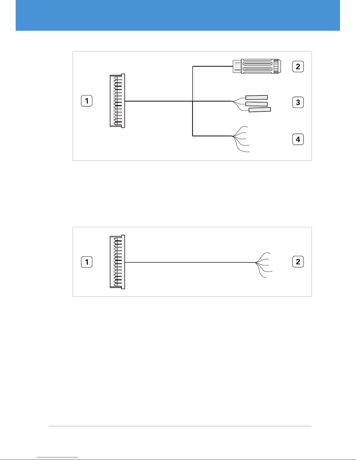
Fig. 12: VRmC-X OEM interface cable for OEM and COB cameras
1 Hirose DF14-15S-1.25C, to be plugged into camera receptacle
2 Switchcraft PC722A receptacle for 5 V power supply
3 Receptacles for 0.1” connector (3 pieces)
4 Open ends (8 pieces, reserved)
1
15
...
Fig. 13: VRmDC/FC-X-DF14- Open interface cable for OEM and COB cameras
1 Hirose DF14-15S-1.25C, to be plugged into camera receptacle
2 Open ends (15 pieces)
21USB Cameras – User Guide
Hardware Installation
USB Components
Page 22
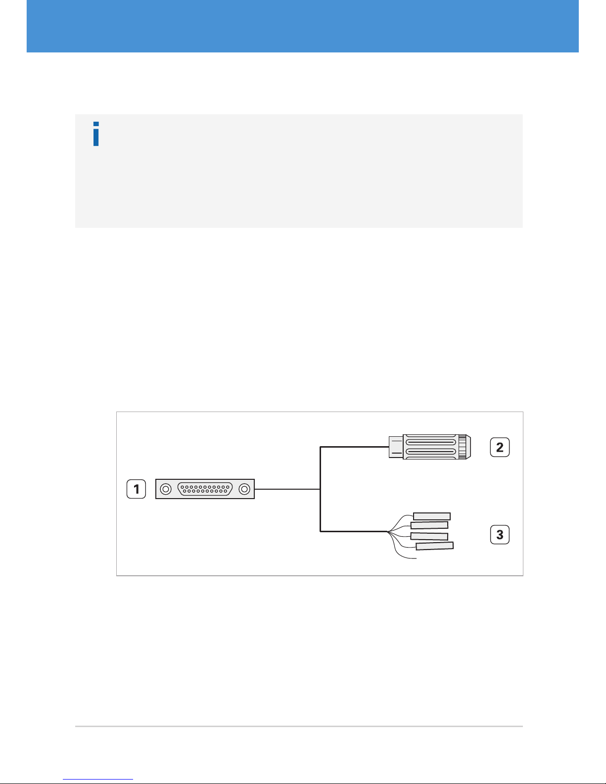
4.2.3 Cameras with MPE Garry Micro-T Connector
Note
The following instructions apply to cameras equipped with a MPE Garry Micro-T
connector only. These are
• all single-sensor cameras in PRO design VRm(F)C-X.
It is assumed that you have ordered the optional “VRmC-X PRO Interface Cable”
( 2.3 on page 13).
Connecting the camera:
1. Connect the supplied cable with the MPE Garry Micro -T plug to the camera’s
receptacle ( Fig. 6 on page11).
2. The other end of the cable splits into 0.1” receptacles for trigger and strobe and a
receptacle for an external power supply. Connect trigger and strobe, if required.
f View the cable plan for a detailed description ( 7.3 on page 36).
3. Connect the USB cable to the camera’s USB port.
4. Continue with 4.3 on page 23 and read the information on power supply.
1 11
12 21
...
Fig. 14: VRmC-X PRO interface cable for PRO cameras
1 MPE Garry Micro-T 387-1-021-ZS0, to be plugged into camera receptacle
2 Switchcraft PC722A receptacle for 5 V power supply
3 Receptacles for 0.1” connector (7 pieces)
USB Cameras – User Guide22
USB Components
Hardware Installation
Page 23
4.2.4 Compact Single-Sensor Cameras
Note
The following instructions apply to compact single-sensor cameras only. These are
• all cameras VRmC-X+ in OEM, COB, or PRO design.
Connecting the camera:
1. OEM and COB cameras only: if required, connect trigger and strobe to the 4-pin
header.
f View the cable plan for a detailed description ( 7.4 on page 37).
2. Connect the USB cable to the camera’s USB port.
3. Continue with 4.3 on page 23 and read the information on power supply.
4.3 Connecting to Power
Most cameras can be powered via the USB connection without an additional external
power supply. Only certain multi-sensor camera models require an external power
supply.
Caution
Additional external power supply necessary with certain multi-sensor
cameras
In the case of a multi-sensor camera with the sensor boards VRmS-9, VRmS-14,
VRmS-16, or VRmS-18, connect an external power supply to the camera as described in the following section.
Only if you are using a multi-sensor camera and the VRmS-12 sensor boards, the
camera may be powered via the USB connection.
23USB Cameras – User Guide
Hardware Installation
USB Components
Page 24

4.3.1 Power Supply via USB
Note
We recommend attaching the USB cable of the camera directly to the PC mainboard without the simultaneous use of other high power USB devices. Alternatively, use an active USB 2.0 hub. The use of passive USB hubs or the connection
to the USB front panel port may not provide enough power to the camera.
If you plan to connect a larger number of USB cameras to the same PC, the power
supplied by the USB ports may not be sufficient. In this case, power the cameras
externally.
Connecting the camera to power via USB:
1. Connect the USB cable attached to the camera to a USB 2.0 port of your host PC.
Do not connect to a USB 3.0 port.
f The status LED starts blinking.
f If you have installed the camera software, the camera should be detected auto-
matically by the host PC. When Windows XP complains about missing WHQL
certification of the driver, click Continue Anyway to complete installation
f The camera is ready to use and the status LED should be on permanently.
USB Cameras – User Guide24
USB Components
Hardware Installation
Page 25

4.3.2 External Power Supply
All multi-sensor cameras except the multi-sensor cameras with VRmS-12 sensor
boards must be connected to an additional external power supply. Single-sensor and
remote-sensor cameras do not need an external power supply.
Use the power supply adapter PHIHONG PSA 15R-050P, if ordered as accessory. Alternatively, use a power supply with the same output values (5 V DC ±5%, at least
15W).
Note
Depending on the accessory kit you ordered ( 2.3 on page 13), the external
power supply must be connected to cables with loose ends or to a 5 V receptacle.
Connecting the camera to an external power supply:
1. Connect the power adaptor to power (multi-sensor cameras only).
2. Connect the power adaptor cable to the camera’s power inlet (multi-sensor cam-
eras only).
3. If you have not already done so, connect the USB cable attached to the camera to
a USB 2.0 port of your host PC. Do not connect to a USB 3.0 port.
f The status LED starts blinking.
f If you have installed the camera software, the camera should be detected auto-
matically by the host PC. When Windows XP complains about missing WHQL
certification of the driver, click Continue Anyway to complete installation
f The camera is ready to use and the status LED should be on permanently.
25USB Cameras – User Guide
Hardware Installation
USB Components
Page 26
5 First Steps
5.1 Auto-Detection of the Camera
If the camera was detected successfully and is operational, the camera’s status LED
should be on permanently. If the status LED continues to blink, this indicates that the
camera was not successfully detected or is not supplied with enough power. In this
case, check that the software was installed correctly or try using a different USB port
that supplies more power.
For a detailed description of the status LED, refer to 7.5 on page 38.
5.2 Starting CamLab
Start the CamLab application to test the functionality of your camera. CamLab allows
you to select the cameras connected to your host PC, view the image recorded by the
image sensor, and change all available camera parameters.
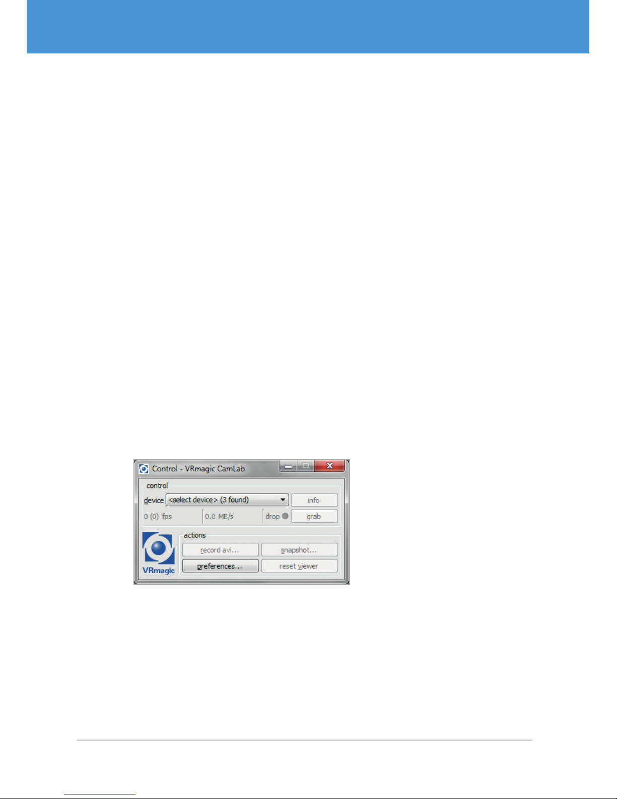
1. Start the CamLab application (Windows: Start > All programs > VRmagic >
CamLab).
f Your camera should be listed in the device list (model name and serial
number).
Fig. 15: CamLab with device list
2. Select your camera from the device list.
f The CamLab control window now displays additional information and camera
parameters. An additional viewer window is also displayed.
USB Cameras – User Guide26
USB Components
First Steps
Page 27
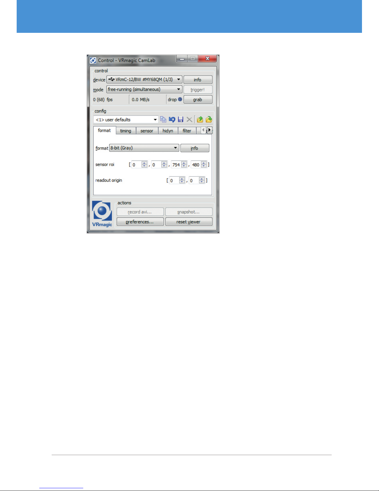
Fig. 16: Camera selected in CamLab
3. Choose grab to view the camera image.
f The camera image is displayed in the viewer window.
4. Try out the different camera parameters. You can change and save parameters in
the config area.
27USB Cameras – User Guide
First Steps
USB Components
Page 28

5.3 Accessing the Demo Applications
Note
The SDK directory is normally
C:\Program Files (x86)\Common Files\VRmagic\VRmUsbCamSDK\
and is read-only. We recommend copying the complete directory including subdirectories to your user directory for testing and development.
Accessing the demo applications under Windows:
1. Navigate to the folder
your-path-to\VRmUsbCamSDK\demos\ .
2. Open the subdirectory for your development platform.
f All demo applications are located there.
Accessing the demo applications under Linux:
Note
To build the demos, you need the SDL library including the development package
installed on your system (SDL and SDL-devel packages).
1. Change to the demo directory, for example:
cd demos/c++/sdlviewer .
2. Build the demo by typing
make .
3. Start the demo by typing
./n a m e_of_exec u table .
USB Cameras – User Guide28
USB Components
First Steps
Page 29
5.4 Using Trigger and Strobe
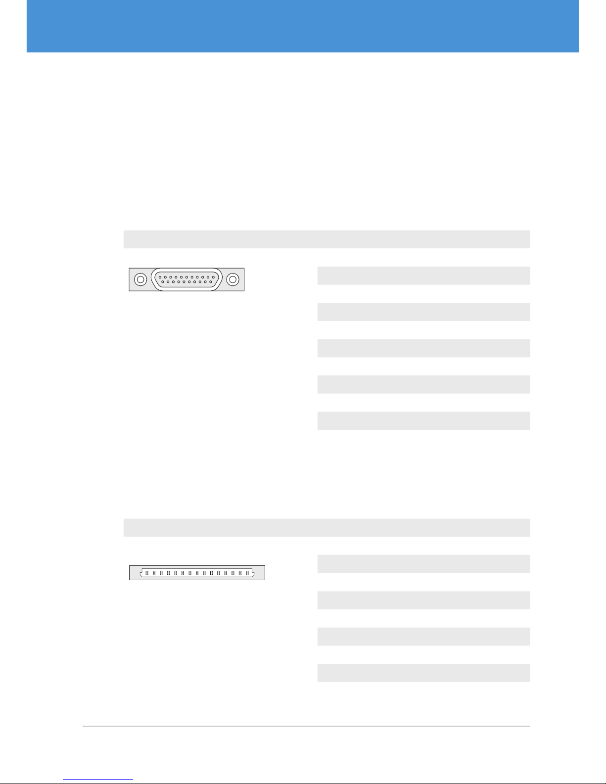
Depending on your camera model, the pins for trigger and strobe are located on different connectors. The following tables show the different connectors and the corresponding pinouts for trigger and strobe. If you are not sure about the location of the
connectors, please refer to 2.2 on page 10.
Single-Sensor Housing Cameras
Camera models: VRm(F)C-X-PRO
Connector Pin Signal
1 11
12 21
MPE Garry Micro-T 386-2-021-ZS0
1 GND
2 Passive Strobe Out– (3...24 V)
3 Passive Strobe Out+ (3...24 V)
4 Active Strobe Out (+5 V)
5 GND
6 Passive Trigger In– (3...24 V)
7 Passive Trigger In + (3...24 V)
8 Active Trigger In (+3.3...5 V)
9 GND
10...11 +5 V
12...21 ...
Single-Sensor Board-Level Cameras, Remote-Sensor Cameras,
Multi-Sensor Cameras
Camera Models: VRm(F)C-X- OEM/COB, VRmC-X-E, VRmMFC
Connector Pin Signal
11
5
Hirose DF14-15P
1...2 +5 V
3 GND
4...7 reserved
8 GND
9 Active Trigger In (+3.3...5 V)
10 Active Strobe Out (+5 V)
11...12 reserved
13 GND
14...15 reserved
29USB Cameras – User Guide
First Steps
USB Components
Page 30
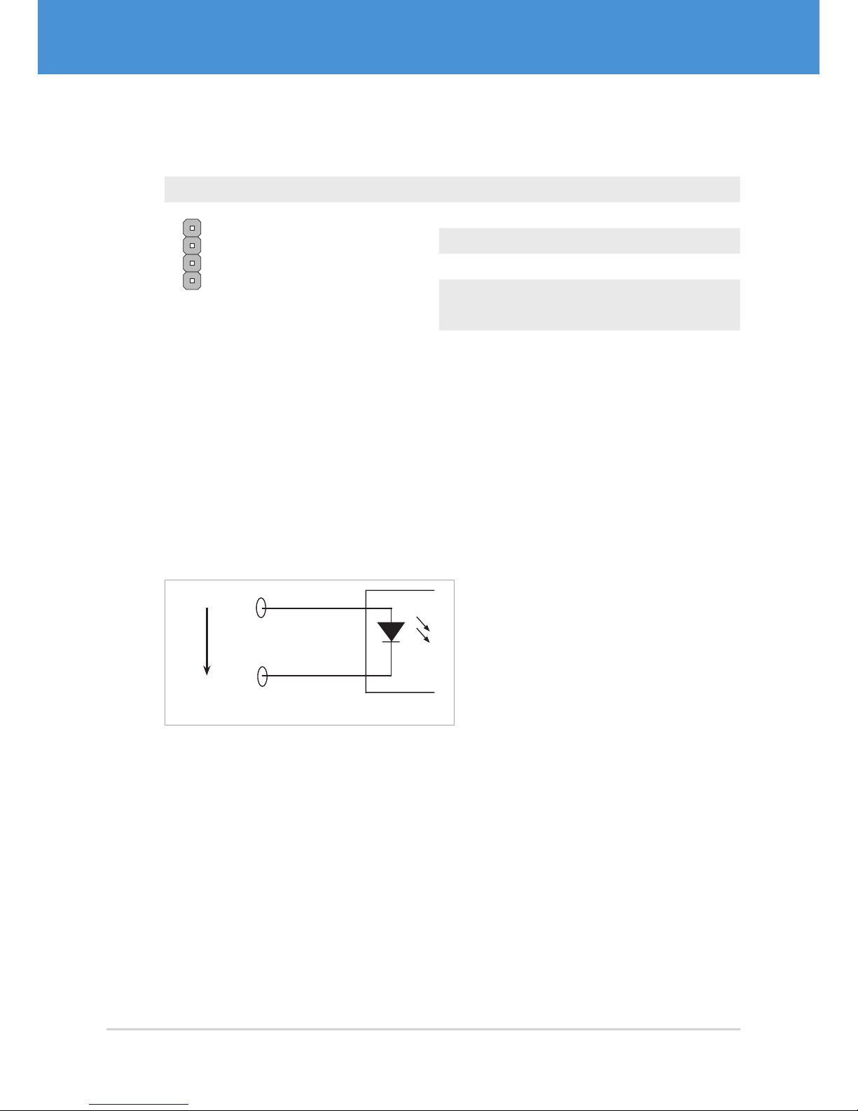
Compact Single-Sensor Board-Level Cameras
Camera models: VRmC-X+ OEM/COB
Connector Pin Signal
T
G
G
S
4
3
2
1
4-pin header
1 Active Strobe Out (+5 V)
2 GND
3 GND
4 Active Trigger In (+3.3...5 V)
5. 4.1 Trigger Input
Passive Trigger Input (potential-free)
The passive trigger input accepts a positive voltage (3...24 V). The signal will be interpreted as logically high when the voltage exceeds 3 V, and as logically low when the
voltage drops below 1V. The current flowing between TriggerIn+ and TriggerIn– is
approx. 2 mA at 3.3 V and approx. 5 mA at 24 V. The active and the passive trigger input
are connected internally and cannot be controlled separately.
3.3V...24V
TriggerIn +
TriggerIn –
Passive Trigger Input
Fig. 17: Passive Trigger Input
Active Trigger Input (TTL)
An LVT TL/TTL compatible signal can be fed in at the active trigger input in reference
to GND. The input features an internal pull-down resistor, input current max. 1 mA.
USB Cameras – User Guide30
USB Components
First Steps
Page 31
5.4.2 Strobe Output
Passive Strobe Output (potential-free)
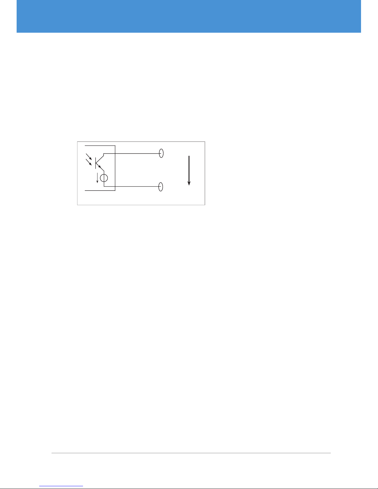
The camera switches an external current between Strobe Out + and Strobe Out – using a potential-free, opto-coupled output transistor. The voltage difference between
Strobe Out + and Strobe Out – must be positive (3...24 V). The output transistor is
capable of switching currents of up to 100 mA. The voltage drop across it will never
fall below 1 V.
Passive Strobe Output
StrobeOut +
StrobeOut -
3.3V...24V
1V
drop
Fig. 18: Passive Strobe Output
Active Strobe Output (TTL)
At the active strobe out is a TTL compatible strobe signal referenced to GND. Active
strobe out can sink or source currents of up to 20mA.
31USB Cameras – User Guide
First Steps
USB Components
Page 32
6 Firmware Update
You should update your camera’s firmware if a newer firmware version is available.
A firmware update might be necessary, for example after updating to the latest SDK.
Warning!
Possible damage to the device
If you unplug the device while the firmware update is in progress, the device will
no longer be functional and may even be physically damaged.
Do not disconnect any device until the update is finished.
Updating the camera firmware:
1. Visit www.vrmagic.com/imaging/downloads/ .
f The firmware for USB cameras can be found beneath the heading “Software
for USB Components”.
2. Download the .zip file VRmUsbCam Firmware Bundle X.Y.
3. Unpack the file.
4. Connect the camera you wish to update to your host PC and be certain it is de-
tected by using CamLab ( 5.2 on page 26).
5. Navigate into the directory created after unpacking the downloaded file in step 3.
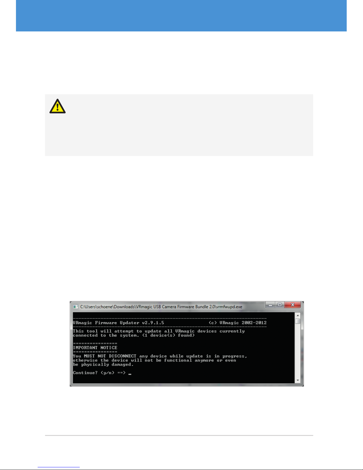
6. Run vrmfwupd.exe by double-clicking on it.
f The Windows command line is displayed.
Fig. 19: VRmagic firmware updater
USB Cameras – User Guide32
USB Components
Firmware Update
Page 33

7. To start the update procedure, type <y> .
f The update starts.
f If the firmware is already up top date, an error is displayed and the update
procedure is canceled.
8. Wait until all VRmagic USB devices have been updated and “Finished” is
displayed.
f You may now unplug the devices or continue working with them.
33USB Cameras – User Guide
Firmware Update
USB Components
Page 34
7 Appendix
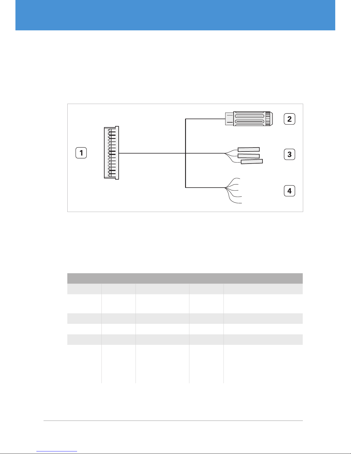
7.1 Cable Plan VRmC-X OEM Interface Cable
1
15
...
Fig. 20: VRmC-X OEM interface cable for OEM and COB cameras
1 Hirose DF14-15S-1.25C, to be plugged into camera receptacle
2 Switchcraft PC722A receptacle for 5 V DC power supply
3 Receptacles for 0.1” connector (3 pieces)
4 Open ends (8 pieces, reserved)
#2 pin #3 wire #4 wire #1 pin Signal
ring 3, 13 GND
center pin 1, 2 +5 V DC (±5%) in / VBUS
out
gray 8 GND
white 9 TTL TriggerIn (+3.3...5 V)
black 10 TTL StrobeOut (+5 V)
yellow1, green1,
blue, purple,
brown2, red2,
yellow2, green2
4, 5,
6, 7,
11, 12,
14, 15
reserved
USB Cameras – User Guide34
USB Components
Appendix
Page 35
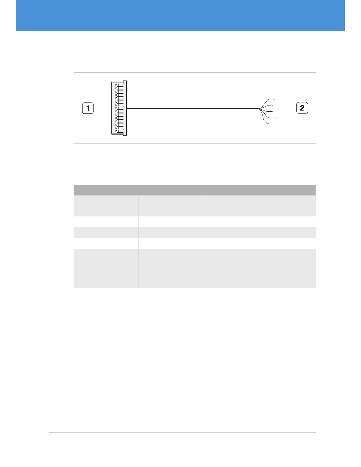
7.2 Cable Plan VRmDC/FC-X-DF14-Open
1
15
...
Fig. 21: VRmDC/ FC -X-DF14-Open interface cable for OEM and COB cameras
1 Hirose DF14-15S-1.25C, to be plugged into camera receptacle
2 Open ends (15 pieces)
#2 wire #1 pin Signal
orange1, gray,
orange2
3, 8,
13
GND
bro w n1, re d1 1, 2 +5 V DC (±5%) in / VBUS out
white 9 TTL TriggerIn (+3.3...5 V)
black 10 TTL StrobeOut (+5 V)
yellow1, green1,
blue, purple,
brown2, red2, yellow2, green2
4, 5,
6, 7,
11, 12,
14, 15
reserved
35USB Cameras – User Guide
Appendix
USB Components
Page 36
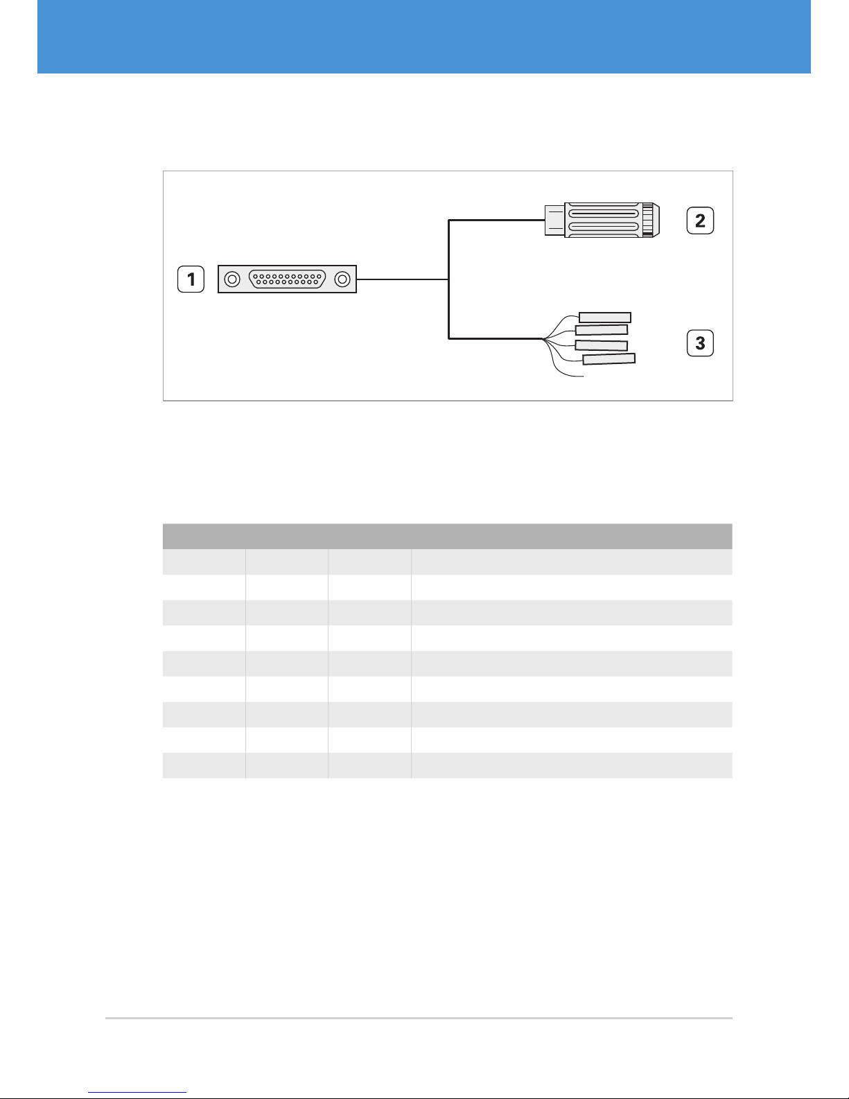
7.3 Cable Plan VRmC-X PRO Interface Cable
1 11
12 21
...
Fig. 22: VRmC-X PRO interface cable for PRO cameras
1 MPE Garry Micro-T 387-1-021-ZS0, to be plugged into camera receptacle
2 Switchcraft PC722A receptacle for 5 V power supply
3 Receptacles for 0.1” connector (7 pieces)
#2 pin #3 wire #1 pin Signal
ring 5, 9 GND
center pin 10 , 11 +5 V DC (±5%) in / VBUS out
white 1 GND
brown 2 StrobeOut – (potential-free)
green 3 StrobeOut + (potential-free)
yellow 4 TTL StrobeOut (+5 V)
gray 6 TriggerIn – (potential-free)
pink 7 TriggerIn + (potential-free)
blue 8 TTL TriggerIn (+3.3...5 V )
USB Cameras – User Guide36
USB Components
Appendix
Page 37
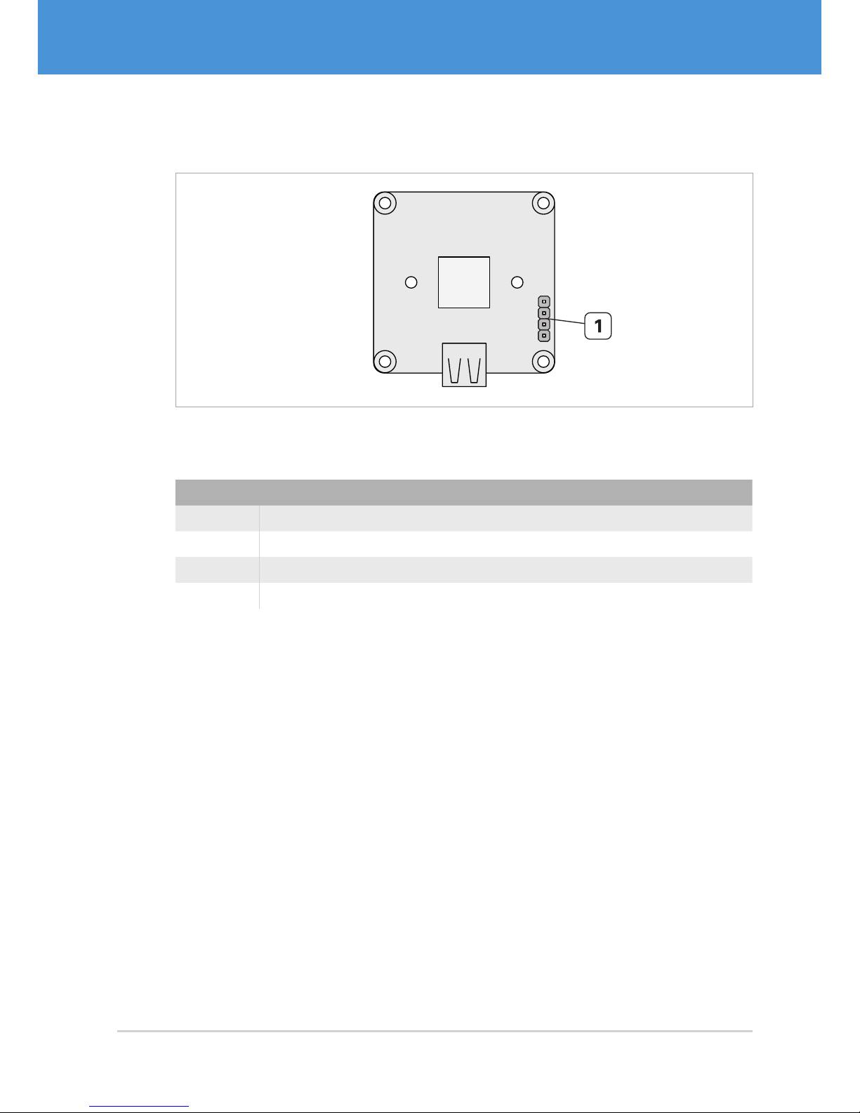
7.4 Pinout 4-pin Header VRmC-X+ OEM/COB
USB
Sensor
T
G
G
S
Fig. 23: 4-pin header of compact single-sensor cameras (OEM/COB)
1 4-pin header for trigger and strobe
#1 pin Signal
T TTL TriggerIn (+3.3...5 V)
G GND
G GND
S TTL StrobeOut (+5 V)
37USB Cameras – User Guide
Appendix
USB Components
Page 38
7.5 Status LED Indications
Note
The compact single-sensor cameras with housing VRmC-X+ PRO do not have a
status LED.
LED indication Meaning
LED off Device has no power or has entered USB suspend mode.
LED blinks Device was not (yet) detected and the driver has not (yet)
been loaded. This status typically occurs for a short time
directly after connecting the device to the PC.
Another reason for this status may be that the device
is not being supplied with sufficient power via the USB
connection.
LED on
(low brightness)
Device was detected and is operational (idle mode).
LED on
(medium brightness)
Device is active and waiting for a trigger signal.
LED on
(high brightness)
An image is currently captured or transferred to the PC.
If the cameras is free-running, the LED glows in high
brightness permanently (except if images are occasionally
dropped).
USB Cameras – User Guide38
USB Components
Appendix
Page 39

8 Index
A
Accessories 13
B
Base unit 8, 9
C
Cable plans 34
Cables 13
VRmC-X OEM Interface Cable 13,
20, 21, 34
VRmC-X PRO Interface Cable 13,
22, 36
VRmDC/FC-X-DF14-Open 13, 20,
21, 35
CamLab 26
Connectors 10
Connect cables 19
DF14-15P 10, 20, 34, 35
MPE Garry Micro-T 11, 22, 36
E
External sensor board 9
F
Firmware update 32
FPGA board 7, 9
I
Interface board 7, 8, 9
Interfaces 10
M
Multi-Sensor Camera 9, 23
P
Pinouts 34
Power supply 13, 23
external 25
via USB 24
R
Remote-Sensor Camera 8
S
Sensor board 7
Sensor connection board 8, 9
Single-Sensor Camera 7
Compact 8, 23
Software 14
Download 14
Install 14
Status LED 10, 11, 24, 25, 26, 38
Strobe 29, 31
T
Trigger 29, 30
U
USB hosts 19
39USB Cameras – User Guide
Index
USB Components
Page 40

USB Cameras – User Guide40
USB Components
Notes
Page 41

41USB Cameras – User Guide
Notes
USB Components
Page 42

USB Cameras – User Guide42
USB Components
Notes
Page 43

Page 44

VRmagic GmbH
Augustaanlage 32
68165 Mannheim
Germany
Phone +49 621 400 416-20
Fax +49 621 40 0 416- 99
[email protected]
www.vrmagic-imaging.com © 2014 VRmagic GmbH, Mannheim
 Loading...