

VRm AreaScan3D User Manual
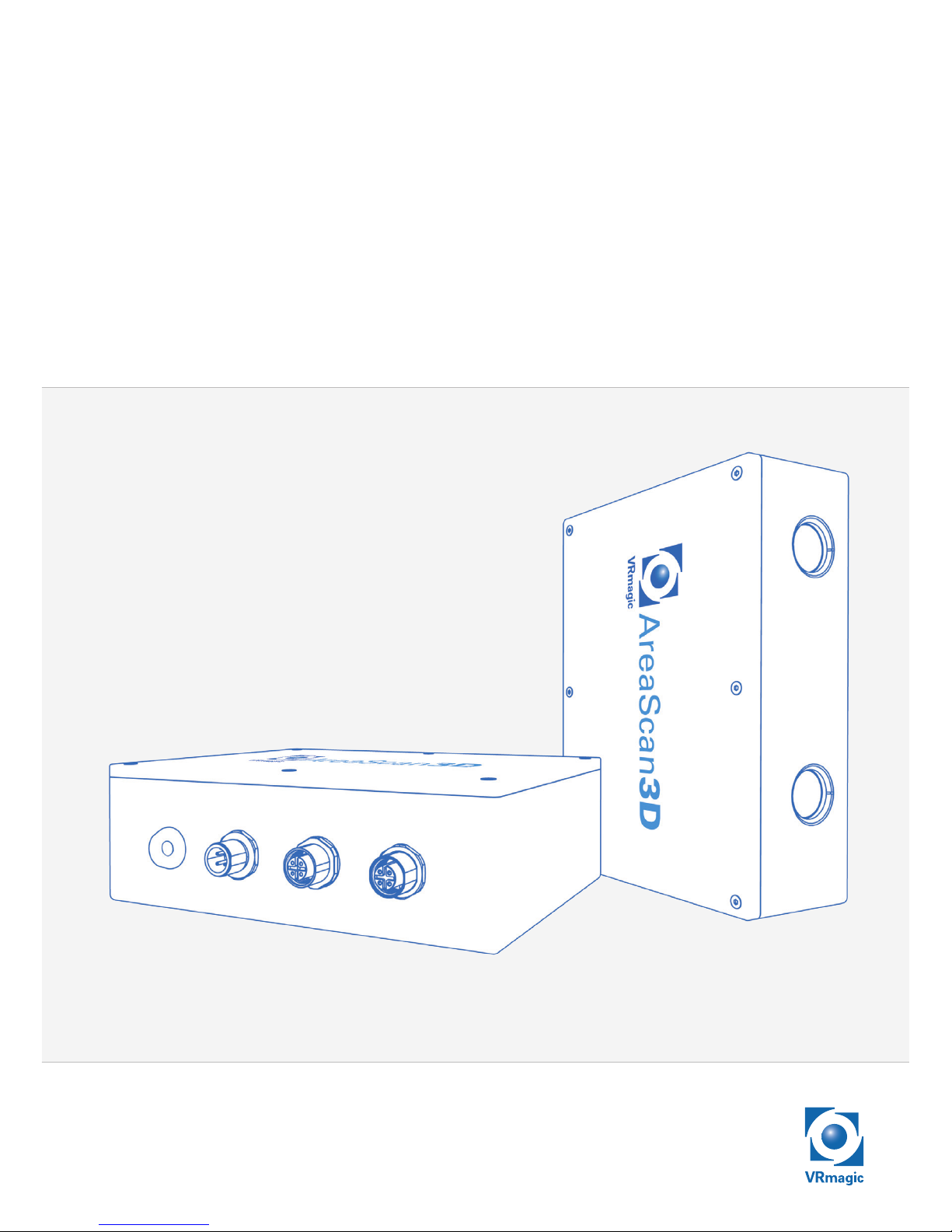
AreaScan3D
Manual

This manual (document version 1.3, date of issue 12/2013) is applicable to the VRmagic AreaScan3D sensor. Subject to technical changes.
The document is protected by copyright. All rights reserved. No part of
this documentation may be reproduced or transmitted for any purpose
in any form or by any means, electronically or mechanically, without
expressly written permission.


4
Table of Contents
1 Product Specifications..................................................................5
1.1 Introduction .............................................................................5
1.2 Scope of Delivery ....................................................................6
1.3 Intended Use ...........................................................................6
1.4 Type Label ...............................................................................6
1.5 Measuring Principle .................................................................7
2 Sensor Design ............................................................................. 11
3 Mounting ..................................................................................... 12
4 Electrical Installation ..................................................................14
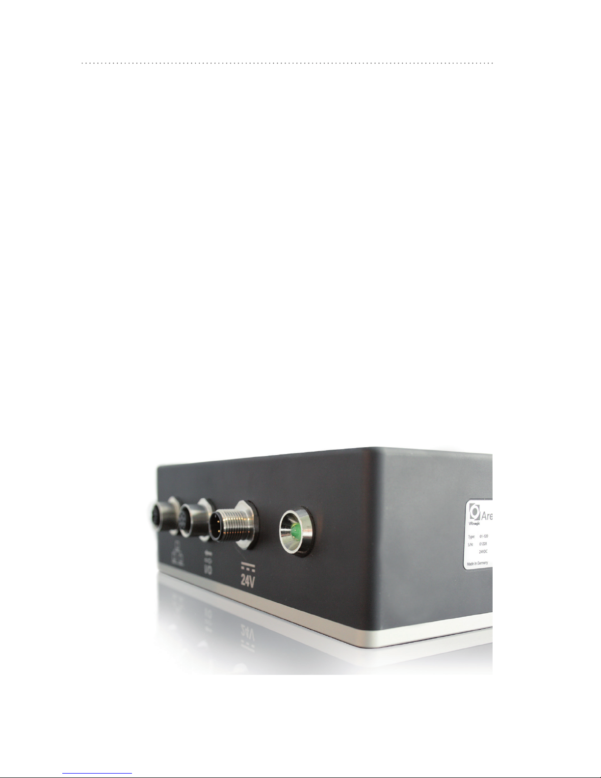
4.1 Connections and Indicators ................................................... 14
4.2 Connecting the Sensor ..........................................................15
5 Operation ....................................................................................17
5.1 Measuring Field Requirements .............................................17
5.2 Positioning the Sensor ..........................................................18
5.3 Positioning the Measured Object .......................................... 19
6 Software / API ..............................................................................21
7 Technical Specifications .............................................................22
7.1 Type-specific data .................................................................22
7.2 General data ..........................................................................23
7.3 Conformity to Standards .......................................................23
8 Troubleshooting ..........................................................................24
8.1 Hardware ............................................................................... 24
8.2 Errors in 3D Image ................................................................25
5
Product Specifications
1 Product Specifications
1.1 Introduction
With the AreaScan3D you hold in your hands a groundbreaking
product in the area of optical 3D measurement, offering the following
highlights:
• Optical 3D sensor based on digital fringe projection,
• Metric calibrated measuring data,
• Export formats: 3D point cloud or height encoding gray level image,
• GenICam transport layer compatible,
• Interfaces to Common Vision Blox & HALCON,
• Aluminum case, IP65 conforming,
• M12 standard industrial connectors,
• 24V operation,
• Ethernet.
6
Product Specifications
1.2 Scope of Delivery
• Sensor, factory calibrated,
• Quickstart manual,
• User guide (this document),
• USB stick with software and documentation.
After delivery, check that the contents of the package are complete.
1.3 Intended Use
The VRmagic AreaScan3D is an area sensor. The device is intended
to provide three-dimensional measurements of surfaces of a certain
area and depth from a predefined distance. The field of application is
industrial image processing. The measurements are transmitted via an
Industrial Ethernet interface as ready-to-use 3D data sets.
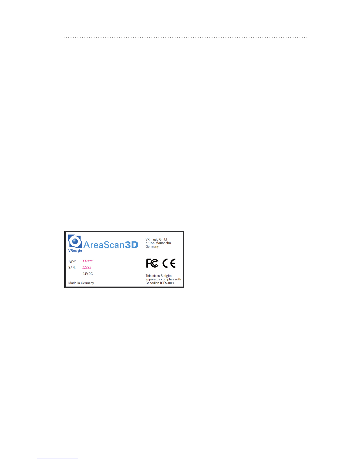
1.4 Type L ab el
Fig. 1: Type Label
7
Product Specifications
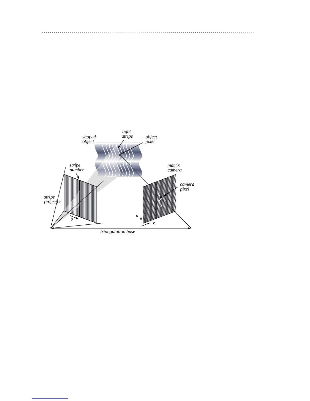
1.5 Measuring Principle
The 3D measurement method implemented in the sensor is based on
triangulation.
Fringes (stripes) are projected onto an object. A camera sees the fringes from a different angle. The perspective deformation of the fringes
seen encodes the 3D coordinates of object points along the fringes.
With this basic principle alone, the distance resolution would depend
on the camera resolution and the triangulation angle.
Fig. 2: Triangulation
8
Product Specifications
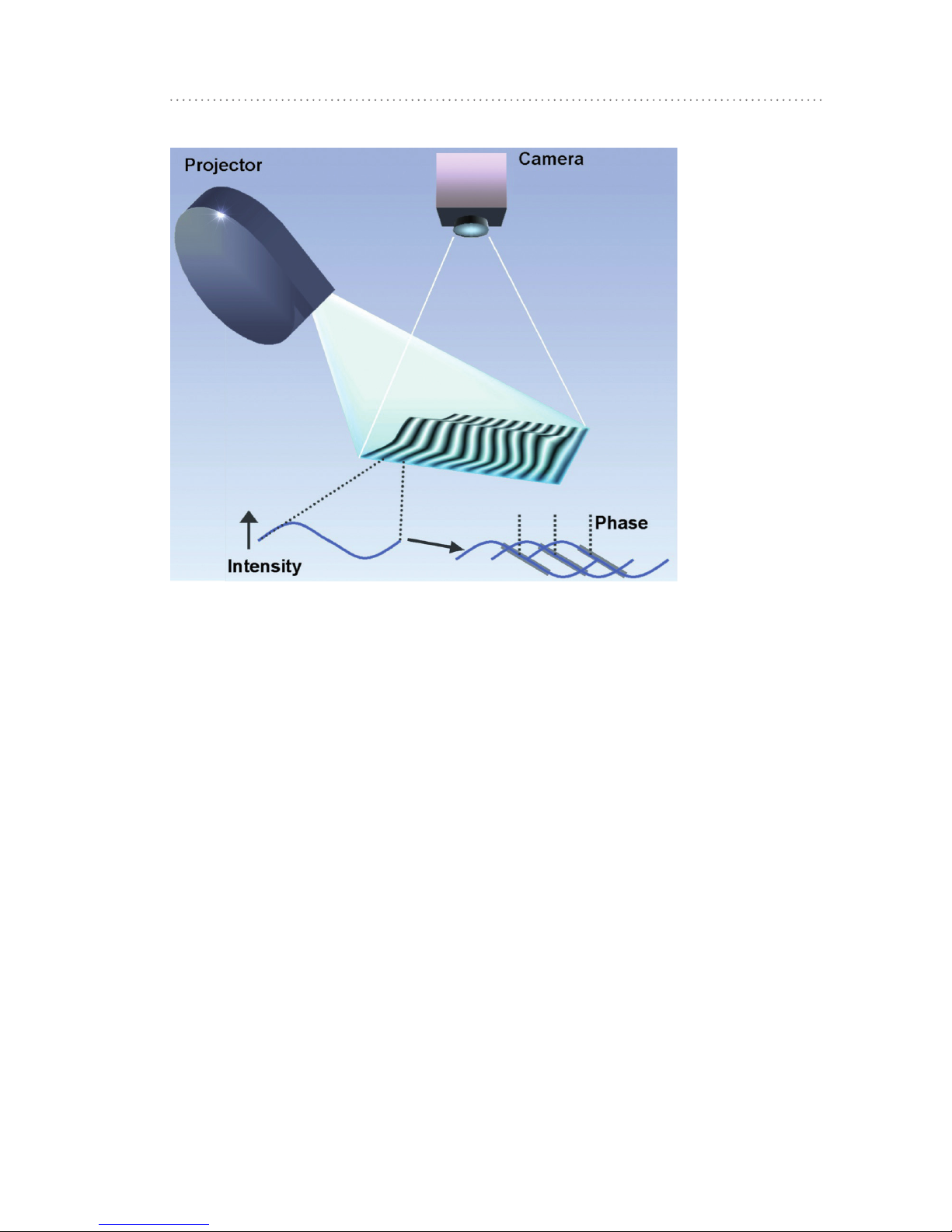
Fig. 3: Phase measurement
Phase measuring fringe projection, however, uses stripes that are not
crisp, but have a sine-shaped brightness modulation. These stripes
can be quite wide, as their position can be determined at high accuracy from the gray levels of the stripe flanks. The distance resolution
here is no longer dependent on the camera resolution. Distance resolution can be measured more than 10 times more accurate, compared
to mere triangulation.

9
Product Specifications
In order to retain phase values for any point on an object, at least 3
fringe patterns with a phase shift of 1/3 fringe width are required (see
following figure). In practice, at least 4 fringe patterns are used.
Fig. 4: Three patterns combined
Repeating patterns deliver no absolute distance indication, however.
On highly fragmented surfaces it would not be possible to clearly identify the single fringes.
In order to assign each fringe seen to a proper distance range, a
sequence of binary patterns is projected. Black and white patterns of
stripes with varying width are used for this (see following figure). The
sequence of brightness values results in a binary number which directly represents the stripe number. This number also indicates which
particular stripe in the phase pattern is seen by a certain pixel of the
camera. Hence, by a combination of binary and phase patterns, even
highly fragmented objects are precisely measured in all detail.
Fig. 5: Binary coded stripes
 Loading...