

Page 1
MS
VRinsight
VRinsight
VRinsightVRinsight
Panel
Page 2

VRinsight
Multi Switch Panel Table of Contents
Table of Contents
Introduction ......................................................................................... 2
General .......................................................................................................... 2
Features ........................................................................................................ 2
Installation .......................................................................................... 4
Connecting the Multi Switch Panel ..................................................................... 4
Calibration ........................................................................................... 5
General .......................................................................................................... 5
Windows 7 (or Vista) ....................................................................................... 5
Windows XP ................................................................................................... 9
Assignment keys/commands to the Multi Switch Panel ..................... 11
Introduction ................................................................................................. 11
Flight Simulator X (or FS2004) ....................................................................... 11
Laminar Research X-Plane 9.x ........................................................................ 14
Falcon 4.0 Allied Force ................................................................................... 16
Appendix ............................................................................................ 17
FSX Standard.xml file .................................................................................... 17
Modifying Standard.xml (FSX) ........................................................................ 17
Modifying FS9.CFG (FS2004) .......................................................................... 18
Copyright © 2010 VRinsight | SimWare Simulations Version: 1.00 | November 8, 2010
www.vrinsight.com | www.simw.com 1 / 18 All Rights Reserved
Page 3

VRinsight
Multi Switch Panel Introduction and Features
Introduction
General
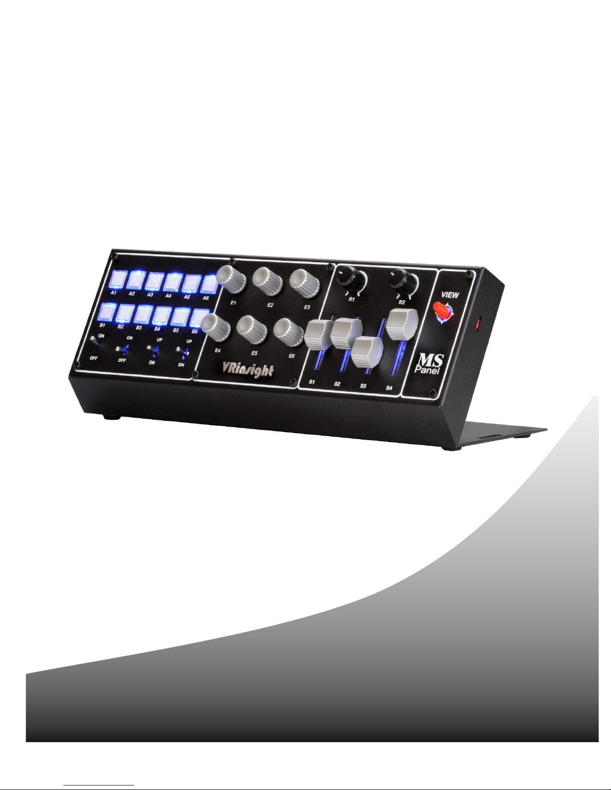
The Multi Switch Panel is a compact unit to control any function available from ALL simulators
and games capable of handling joystick inputs. Because of this, the installation as a joystick
makes it easy as well as commands/key assignments. Due to its design, the VRinsight Multi
Switch panel will fit needless with other VRinsight flight panel products like the MCP Panel,
CDU II, and Instrument RadioStack or even with the JetPit or ProPit.
Combinations are endless!
The Multi Switch Panel black box offers the following parts:
• Multi Switch Panel complete with angled bracket,
• A DVD with this User Guide, standard.xml sample file, MSFS_Controls text file and
several VRinsight product instruction movies and Wilco Publishing promotion movies.
• An “Application Instruction” sheet with three removal tools and attached to it, a
pushbutton placards sheet.
Features
The following offers all the features of the VRinsight Multi Switch Panel.
• Fully compatible with all simulators:
- Flight Simulator X and FS2004,
- Falcon 4,
- IL-2 Sturmovik,
- Black Shark,
- Lock ON,
- X-Plane,
- Ship Sim Extremes,
- Space Shuttle etc.
• Plug & Play installation.
• No driver required.
This means it’s fully programmable directly from your simulators or FSUIPC.
• Full metal case.
• A USB 2.0 cable connection.
• Panel backlight, which is always ON.
• Ten push buttons.
• Two 2-positions ON/OFF toggle switches.
• One return toggle switch.
• One 3-position ON/OFF toggle switch.
• Six encoder switches.
• Two potentiometers.
• Four sliders.
• One four position HAT view button.
• Measurements:
Length: 30.5cm (12 inch)
Width: 12.5cm (4.9inch)
Height: 11cm (4.3 inch).
• Weight: 1.5kg
• 1 year warranty.
Copyright © 2010 VRinsight | SimWare Simulations Version: 1.00 | November 8, 2010
www.vrinsight.com | www.simw.com 2 / 18 All Rights Reserved
Page 4
VRinsight
Multi Switch Panel
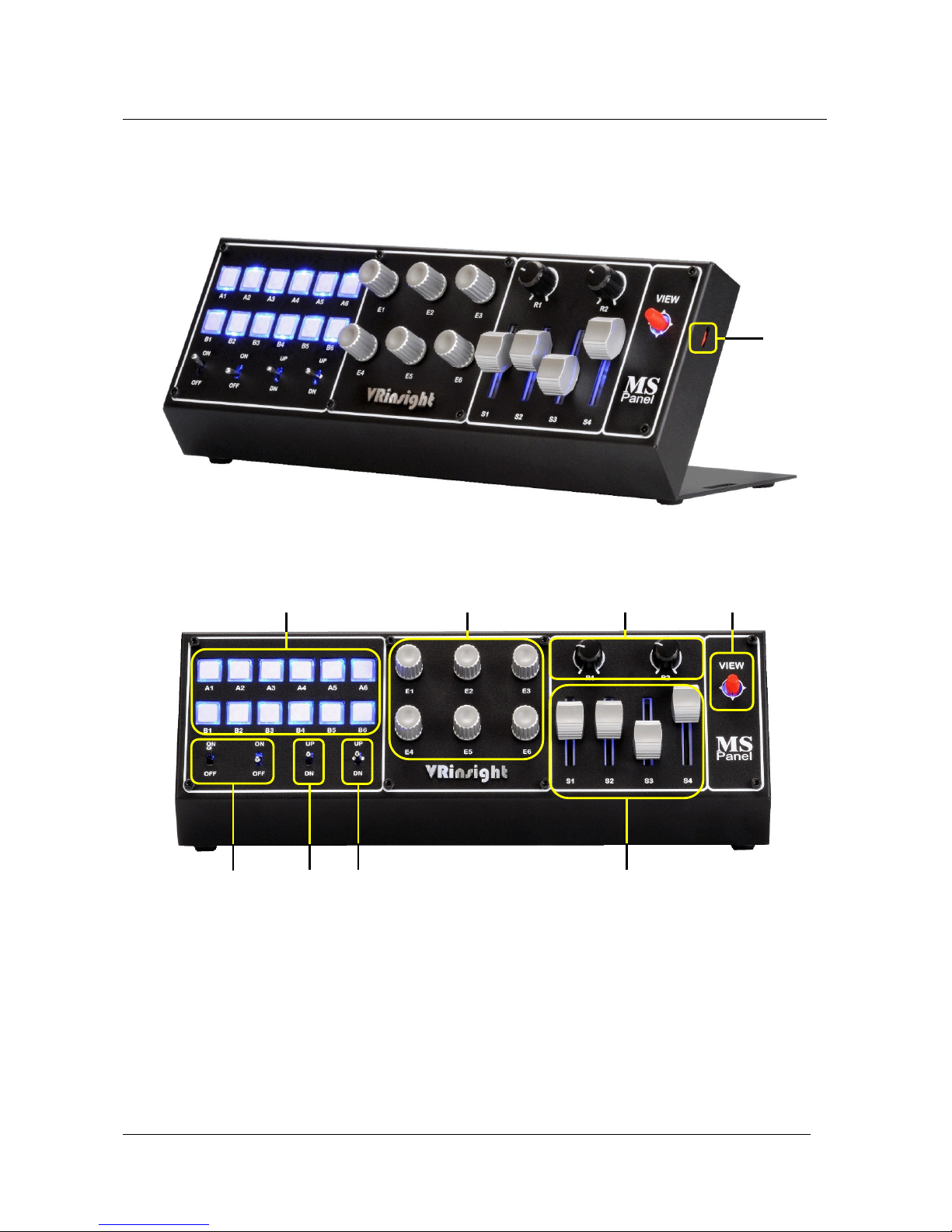
These two images of the Multi Switch Panel show you the identification of the used push
buttons, switches, knobs, encoders and sliders.
Introduction and Features
A
B C D E
F G H
A Fast Rotate and Hold feature for rotary encoders “D”
B Pushbuttons (12)
C Encoder switches (6)
D Potentiometers (2)
E Four positions view button (1)
F Two positions ON-OFF toggle switches (2)
G Return toggle switch (1)
H three positions ON-OFF toggle switch (1)
J Sliders (4)
J
Page 5

VRinsight
Multi Switch Panel
Installation
Connecting the Multi Switch Panel
Since the Multi Switch Panel comes only with one USB cable, hardware installation will be as
easy as possible. Remember that the USB receptacle should be USB 2.0 compliant else
problems could arise. Follow these steps for a successful hardware installation. Although the
following steps represent Windows Vista/7 installation, the Multi Switch panel is also
compatible with Windows XP.
• Connect the USB cable of Multi Switch panel to a USB PC receptacle or to a USB 2.0 hub.
• The Multi Switch panel is recognized as a new Human-Interface Device (New Hardware).
• Check all four parts of the Multi Switch panel are illuminated. This means the blue
backlight behind the pushbuttons, switches, sliders and HAT switch should illuminate at
the light blue marked areas down below.
Note: The blue LED light will be dimmed in a bright environment.
Installation
Page 6
VRinsight
Multi Switch Panel
Calibration
General
Since the Multi Switch panel is recognized as a joystick, it must be calibrated before using it.
Hardware calibration examples are given for working with Windows 7 and Windows XP-SP3.
Because of the similarity with Windows Vista, no calibration example of this Operating System
is included. The actual Windows calibration is for all Windows system the same and therefore
only screenshot in relation to Windows 7 are shown.
Windows 7 (or Vista)
Step 1
Assignment Procedures
Connect your Multi Switch panel to a USB 2.0
receptacle.
Step 2
Step 3A - Category view
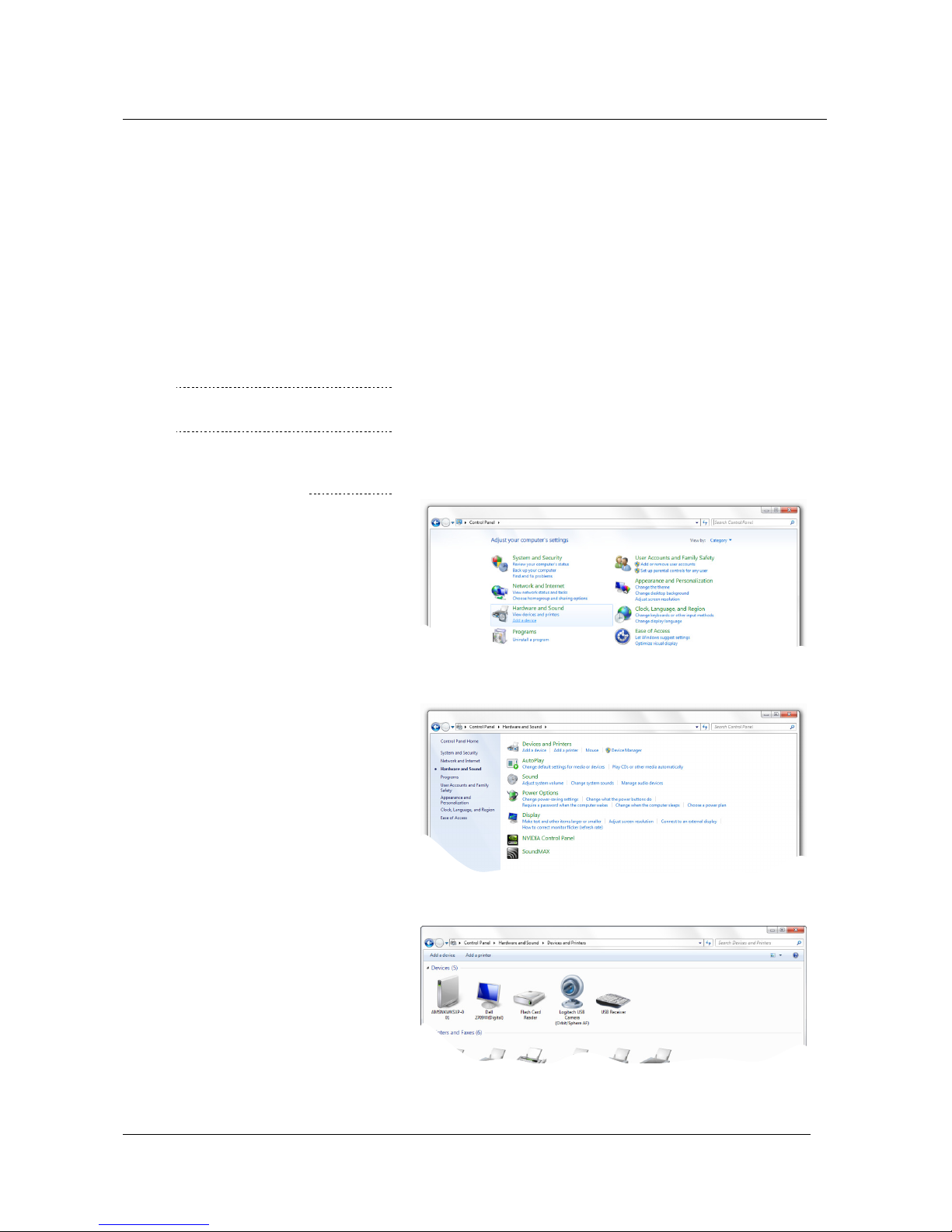
Open the Windows Control Panel.
Either you have Category view or Large (small Icons)
view active. For Category view follow step 3A else 3B.
- Click Hardware and Sound.
- Click Devices and Printers.
- Right click the usb pad icon and chose
Game controller settings.
Page 7

VRinsight
Multi Switch Panel
Step 3A - Category view (con’t)
Assignment Procedures
- The Game Controllers window appears.
- Click the Properties button.
- Continue with step 4.
Step 3B – Large (small) Icon view
Step 5
- Click the Devices and Printers icon.
- This will bring you to the 3rd screenshot of step 3A
thus right click the usb pad icon and chose
Game controller settings.
- The Game Controllers window as you can see above
appears. Click the Properties button.
- Click the Settings tab in the usb pad properties
window followed by the Calibrate button.
Step 6
- The Welcome to the Device Calibration Wizard
appears. Start the wizard by clicking the Next>
button. Continue till the Axis Calibration appears.
Page 8

VRinsight
Multi Switch Panel
Step 7
Assignment Procedures
- Gently rotate knobs R1 and R2 several times from
left to right and follow their output on the screen.
Note: Knob R1 will move “+” left to the right and
knob R2 will move “+” up and down).
- When done, click the Next> button.
Step 8
Step 9
- The Axis Calibration Z Axis window appears.
- Move S1 slider, which is recognized as Z axis,
up and down and check for movement of the blue bar
down below.
- When you are ready, click the Next> button.
- The Axis Calibration for X Rotation appears.
- Move S2 slider, which is recognized as X Rotation,
up and down. Check for correct blue bar movement.
- When you are ready, click the Next> button.
Page 9

VRinsight
Multi Switch Panel
Step 10
Assignment Procedures
- The Axis Calibration for Rudder window appears.
- Move S3 slider, which is recognized as Rudder,
up and down.
- Click once more the Next> button.
Step 11
Step 12
- The Axis Calibration for Throttle windows appears.
- Move S4 slider, which is recognized as Throttle,
up and down.
- Click Next> and finish the Calibration Wizard.
This concludes the calibration procedure for the
sliders and rotary encoders R1 and R2.
- Select the Test tab as shown below.
- Move and/or press all Multi Switch panel buttons,
switches, knobs and sliders and check for their
correct output on the usb pad properties window.
- When you are finished with testing are the switches,
buttons, sliders and knobs, click the OK button.
Page 10

VRinsight
Multi Switch Panel
Windows XP
Since the Game Device Calibration is more or less the same for every Windows version, this
Windows XP section only covers those parts that differ from Windows 7 (or Vista). Once you’ve
reached Windows XP step 4, you continue with the device calibration of the previous section.
Step 1
Assignment Procedures
- Connect your Multi Switch panel to a USB 2.0
receptacle.
Step 2
Step 3A (Category view)
- Open the Windows Control Panel.
- Either the contents comes up with Category view or
Classic view. For Category view take step 3A else 3B.
- Click Printers and Other Hardware.
- Click Game Controllers icon.
- This will lead you to the Games Controllers window
with the usb pad joystick or actually the Multi Switch
panel.
- Click the Properties button.
Page 11

VRinsight
Multi Switch Panel Assignment Procedures
Step 3B (Classic view)
- Click “Game Controllers” icon.
Step 4
- This will lead you to the Games Controllers window
with the usb pad joystick or actually the Multi Switch
panel.
See for this the 3rd screenshot on the previous page.
- To continue with the test, click the Properties button
on the Game Controllers window.
- Click the Settings tab in the usb pad properties
window followed by the Calibrate button.
For actual Windows XP usb pad calibration; go to
page 6, step 6 of the Windows 7 (or Vista) section.
Copyright © 2010 VRinsight | SimWare Simulations Version: 1.00 | November 8, 2010
www.vrinsight.com | www.simw.com 10 / 18 All Rights Reserved
Page 12

VRinsight
Multi Switch Panel
Assignment keys/commands to the Multi Switch Panel
Introduction
Calibrating the Multi Switch panel is essential for correct operation with Microsoft Windows
Operating Systems. Once this calibration is completed, assigning keys and/or commands to
the various pushbuttons, knobs, sliders and switches on the Multi Switch panel is essential to
get it “customized” with the simulator. This section deals with some examples of how to assign
keys/commands to the panel. Because the panel is recognized as an ordinary joystick, the
assignment procedure is not different than other hardware. Although the assignment
procedure is not much different compared to other joysticks, find in this section a Microsoft
Flight Simulator X (or FS2004), Laminar Research X-Plane 9.x and Falcon 4.0 examples.
Flight Simulator X (or FS2004)
Step 1
Assignment Procedures
- If not yet done, connect the Multi Switch Panel USB
cable to a USB 2.0 receptacle.
- Start FSX. Either FSX starts up with a default flight or
you will get the FSX startup window.
- When FSX comes up with the startup window, select
on the left side Settings, followed by Controls.
- When FSX comes up with a default flight, select from
the menu Options – Settings - Controls.
Page 13

VRinsight
Multi Switch Panel
Step 2
Assignment Procedures
- By default the Settings-Controls window shows up
with the Calibration tab active.
Confirm that the Controller Type shows usb pad.
Step 3
Step 4
- Click the BUTTONS/KEYS tab.
- Select from the Event Category list an event of your
choice. For this example we take the Autopilot.
-
As you can see on the screenshot, event Category
Autopilot is active. I want to assign event Autopilot
master (on/off) to VRinsight Multi Switch panel
pushbutton B6. To achieve this, perform the
following actions.
- If already a joystick is assigned to this, click the
Delete Joystick Assignment button.
- Click the New Assignment button.
Page 14

VRinsight
Multi Switch Panel Assignment Procedures
Step 5
- Press pushbutton B6 (or any other) on the Multi
Switch Panel.
This Multi Switch panel button B6 is recognized in
FSX as button 12, which is of no further use.
- Click the OK button to confirm your action.
Step 6
Step 7
As you can on the screenshot, Autopilot master
(on/off) is actually assigned to FSX Joystick Button 12,
but more important, to your Multi Switch panel
pushbutton B6.
- Perform the previous steps and apply this to all
buttons, switches, rotary knobs, encoders and
sliders.
Note: If the VRinsight Multi Switch panel is your
only simulation hardware components then
you use the Control Axis tab for assigning
Rudder, Throttle, X Rotation and Z axis.
The procedure to do this is the same as the
previous discussed steps.
Copyright © 2010 VRinsight | SimWare Simulations Version: 1.00 | November 8, 2010
www.vrinsight.com | www.simw.com 13 / 18 All Rights Reserved
Page 15

VRinsight
Multi Switch Panel
Laminar Research X-Plane 9.x
Step 1
Assignment Procedures
- If not yet done, connect the Multi Switch Panel USB
cable to a USB 2.0 receptacle.
- Start X-Plane 9.x and select from the X-Plane menu
Settings – Joystick, Keys & Equipment.
Step 2
Step 3
Basically, assigning keys, buttons, knobs, sliders etc. is
very similar to Microsoft Flight Simulator. The only
difference is the way it is created and organized.
The Axis tab allows you to assign Multi Switch panel
sliders to an X-Plane function. Perform the following
steps:
- Slider S1 on the VRinsight panel is moved up and
down. On the X-System window this is the 3rd LH red
bar from the top.
- Click on the text left of the red bar.
- A pull-down list appears. Select one of your choices.
Here we selected pitch.
- After you selected pitch, the red bar becomes green
and shows pitch left of it, indicating this is assigned
to the pitch channel on your Multi Switch panel.
Page 16

VRinsight
Multi Switch Panel Assignment Procedures
Step 4
Assigning Multi Switch panel pushbuttons goes in the
same way however, for this we need the Buttons:Basic
tab.
As an example we assign Multi Switch panel switch T3
to the GEAR UP/DOWN command.
- If not yet done, select the Buttons: Basic tab.
- Toggle Multi Switch panel switch T3 to DN. The XSystem shows in the LH upper corner 15 (or another
value).
- Click the circle next of the Landing gear down text.
- The assignment of the GEAR DN command is done.
See the output on the screenshot below.
Step 5
Step 6
- Do the same with the Multi Switch panel switch T3 to
UP. This should give you in the LH upper corner value
14 or another value.
- Click the circle next of the Landing gear up text.
- The assignment of the GEAR UP command is done.
- Perform the previous steps and apply this to all
buttons, switches, rotary knobs, encoders and
sliders. Additional assignment information can be
found in the X-Plane User Manual.
Copyright © 2010 VRinsight | SimWare Simulations Version: 1.00 | November 8, 2010
www.vrinsight.com | www.simw.com 15 / 18 All Rights Reserved
Page 17

VRinsight
Assignment Procedures
c
Falcon4AF_patch_1.0.13 should be installed
function for A1 ~ B6, T1 ~ T4, E1 ~ E4.
Click the Apply button and save the file.
- Go to CONTROLLERS and chose from the FLIGHT
Rotate R1 and R2. Knob R1 will be assigned as
Move up switch T1 and switch T3 up and down.
T1 is then assigned as Throttle and T3 as rudder.
When you are finished, click the OK button to save
Multi Switch Panel
Falcon 4.0 Allied Force
Step 1
- If not yet done, connect the Multi Swit
cable to a USB 2.0 receptacle.
h Panel USB
Step 2
Step 3
- Run Falcon and go to SETUP-KEYS.
Note:
before use.
- Assign
-
CONTROLLERS dropdown list usb pad.
aileron and knob R2 as elevator.
-
the changes.
Page 18

VRinsight
Multi Switch Panel Appendix
Appendix
FSX Standard.xml file
Actually, Microsoft’s Flight Simulator X has more than hundred possible controls, which are not
listed in the previous discussed Control Assignments of the Settings page.
To assign unlisted commands for operation with the VRinsight Multi Switch Panel, the user can
manually edit the FSX Standard.xml file.
The DVD comes with a MSFS_Controls.txt that lists all the possible FS commands of which only
a limited amount is available via the Settings-Controls window. Furthermore the DVD comes
with an example standard.xml, which should not be used. This file offers only possible
assignments and is not replacing your whole standard.xml file.
Users are able to manually modify the standard.xml file with the help of the MSFS_Controls.txt
file. This should only be done when the basic FSX/FS2004 commands are not enough.
Editing commands within FS2004 (FS9) is done in the same way however, for this the FS9.cfg
(configuration file) should be used.
Modifying Standard.xml (FSX)
In case you want to modify your FSX Standard.xml file, you have two options; either you
assign keys/commands within FSX (easiest and practical way). Using this method is easy and
practical. Assignment changes made in FSX are stored in the standard.xml file.
Another option is in combination with the supplied MSFS_Controls.txt file. You then modify the
standard.xml file directly. When you are looking for this option, follow the next steps:
- For Windows Vista/7 users:
Go to “X”:\Users\your_name\AppData\Roaming\Microsoft\FSX\Controls.
Note: Since “AppData\Roaming” is a hidden directory, you need to type the whole
directory path. Instead of <your_user> you put your own name e.g.
“X”:\Users\Angelique\AppData\Roaming\Microsoft\FSX\Controls where “”X”
should be replaced by the FSX drive letter.
- For Windows XP users you go to:
“X”:\Documents and Settings\<your_name>\Application Data\Microsoft\FSX\Controls.
Note: Since “Application Data\” is a hidden directory, you need to type the whole
directory path and instead of <your_user> you put your own name.
- Your own standard.xml file offers, with the usb pad connected, two entries:
<Name>usb pad{DEAAC6B0-E5A6-11DF-8001-444553540000}</Name> and
<Name>usb pad SLEW {DEAAC6B0-E5A6-11DF-8001-444553540000}</Name>.
Note: All the characters between {xxxxxx xxxx etc} will differ on your PC.
- Where you need to look for is the <Name>usb pad section.
Find here an example of a standard.xml, section <Name>usb pad:
<Entry>
<Index>5</Index>
<Down>AP_MASTER</Down>
</Entry>
<Entry>
<Index>6</Index>
<Down>AP_N1_HOLD</Down>
</Entry>
- For example, bold text – AP_MASTER – is an assignment that can be found in the
MSFS_Controls.txt file as well. By changing this name and thus the assignment, you
can change the function of Multi Switch panel button, switch, knob etc.
Copyright © 2010 VRinsight | SimWare Simulations Version: 1.00 | November 8, 2010
www.vrinsight.com | www.simw.com 17 / 18 All Rights Reserved
Page 19

VRinsight
Multi Switch Panel Appendix
Modifying FS9.CFG (FS2004)
FS9 key/command assignments are very similar to that of FSX however; assignment changes
are not made in the standard.xml file, but in FS9.CFG.
- For Windows Vista/7 users:
Go to “X”:\Users\<your_name>\AppData\Roaming\Microsoft\FS9.
Note: Since “AppData\Roaming” is a hidden directory, you need to type the whole
directory path. Instead of <your_user> you put your own name e.g.
“X”:\Users\Angelique\AppData\Roaming\Microsoft\FS9 where “”X” should be
replaced by the FSX drive letter.
- For Windows XP users:
Go to “X”:\Documents and Settings\<your_name>\Application Data\Microsoft\FS9.
Note: Since “Application Data\” is a hidden directory, you need to type the whole
directory path and instead of <your_user> you put your own name.
- Your own fs9.cfg file offers, with the usb pad connected, the following entry:
[JOYSTICK_MAIN {DEAAC6B0-E5A6-11DF-8001-444553540000}].
Note: All the characters between {xxxxxx xxxx etc} will differ on your PC.
- Where you need to look for is the [JOYSTICK_MAIN xxxx] section.
- Find here an example of a fs9.cfg file:
AXIS_EVENT_00=AXIS_AILERONS_SET
AXIS_SCALE_00=64
AXIS_NULL_00=36
AXIS_EVENT_01=AXIS_ELEVATOR_SET
AXIS_SCALE_01=64
AXIS_NULL_01=36
AXIS_EVENT_02=AXIS_THROTTLE_SET
AXIS_SCALE_02=127
AXIS_NULL_02=1
AXIS_EVENT_03=AXIS_RUDDER_SET
AXIS_SCALE_03=64
AXIS_NULL_03=36
AXIS_EVENT_05=AXIS_RUDDER_SET
AXIS_SCALE_05=64
AXIS_NULL_05=36
BUTTON_DOWN_EVENT_00=BRAKES
BUTTON_DOWN_REPEAT_00=1
BUTTON_DOWN_EVENT_01=VIEW_MODE
BUTTON_DOWN_EVENT_02=ELEV_TRIM_DN
BUTTON_DOWN_REPEAT_02=1
BUTTON_DOWN_EVENT_03=ELEV_TRIM_UP
BUTTON_DOWN_REPEAT_03=1
BUTTON_DOWN_EVENT_06=KNEEBOARD_VIEW
BUTTON_DOWN_EVENT_07=GEAR_TOGGLE
BUTTON_DOWN_EVENT_08=VIEW_MODE
BUTTON_DOWN_EVENT_09=GEAR_TOGGLE
BUTTON_DOWN_EVENT_14=FLAPS_DECR
BUTTON_DOWN_EVENT_15=FLAPS_INCR
POV_MOVE_EVENT_00=PAN_VIEW
POV_MOVE_REPEAT_00=1
Find right below an extraction from my own FS9.CFG related to this particular section.
The “AXIS” refers to sliders when it comes to the Multi Switch panel and “BUTTON”
items to for example the pushbuttons.
Copyright © 2010 VRinsight | SimWare Simulations Version: 1.00 | November 8, 2010
www.vrinsight.com | www.simw.com 18 / 18 All Rights Reserved
 Loading...