

VRinsight MCP combo panel User Manual

MCP combo panel
USER MANUAL
Please read this manual before operating your
units and keep it for future reference.
All stated here is subject to change without advanced notice for improvement.
Tel : +82-31-284-7090~91 Fax : +82-31-284-7092 E-mail : tech@vrinsight.com Web site : www.vrinsight.com
VRinsight
Virtual Reality Insight
Virtual Reality Insight
1
BEFORE USE : Thanks for purchasing VRi’s MCP Combo panel.
Before operating your units, please read through this manual and keep it for future reference.
For any further question, visit www.wilcopub.com or contact us below:
Fax : +32-2-33107 51
E-mail (Support team) : info@wilcopub.com
NOTE : This manual could be redistributed unless you modify the contents.
This manual has been written out on a Serial FP v2/Jet Liner’s MCP combo
panel basis.
All software (& software versions) stated here is subject to change without advanced
notice for improvement.
If you want to download the latest driver version for panel & application
programs, visit www.vrinsight.com
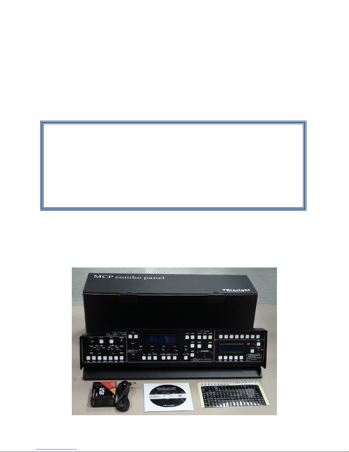
Box contents
2
VRinsight MCP combo panel
simple connection your computer through USB. Package including universal power supply
The MCP combo panel of VRinsight features various types of aircrafts’ panel with full
control complement ; default aircrafts of MSFS, most freeware and commercial add-on
aircraft (Wilco’s B737 Classic, PMDG’s B737NG & 744, Level-D’s B767-300 and PSS’
A319,320,330,340). It is completely interfaced with MSFS9 and MSFSX through add-on
software “VRiSim” which enables MCP combo panel to perform full simulation with
adaptor (DC 5V).
The MCP combo panel is comprised of EFIS, MCP & COM (Instrument Radio) part to
understand advanced flight controls for beginners and less advanced users starting flight
simulation games at a first step.
Each control part; EFIS, MCP & COM has push buttons, rotary knobs, toggle S/Ws and/or 2
line character type LCDs offers actual flight circumstance with full control complement.
• VRiSim supports all functions to MCP combo panel
• MCP combo panel consumes high power. To avoid malfunction , do not use many other
USB interfacing devices. We recommend using external power supply (DC 5V adaptor)
• If you want to use a USB hub, be sure that the USB hub is USB 2.0 compliant.
Otherwise it may cause a malfunction.
3
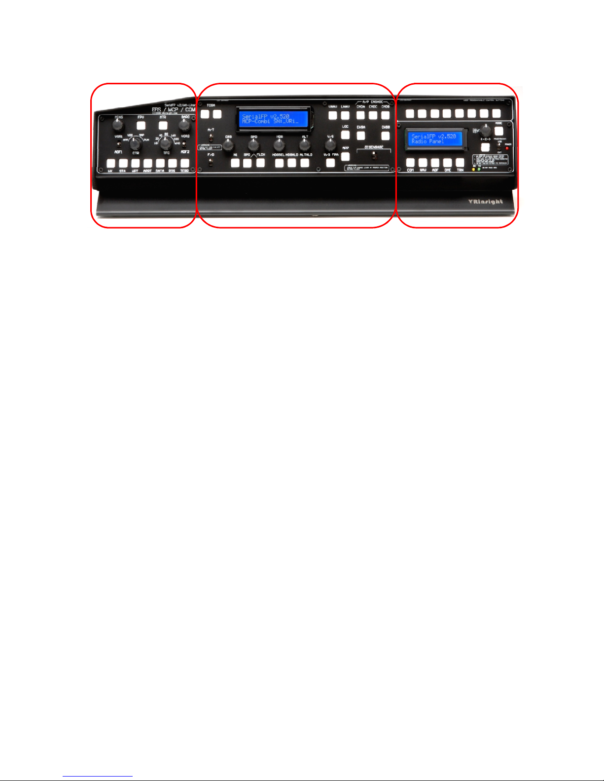
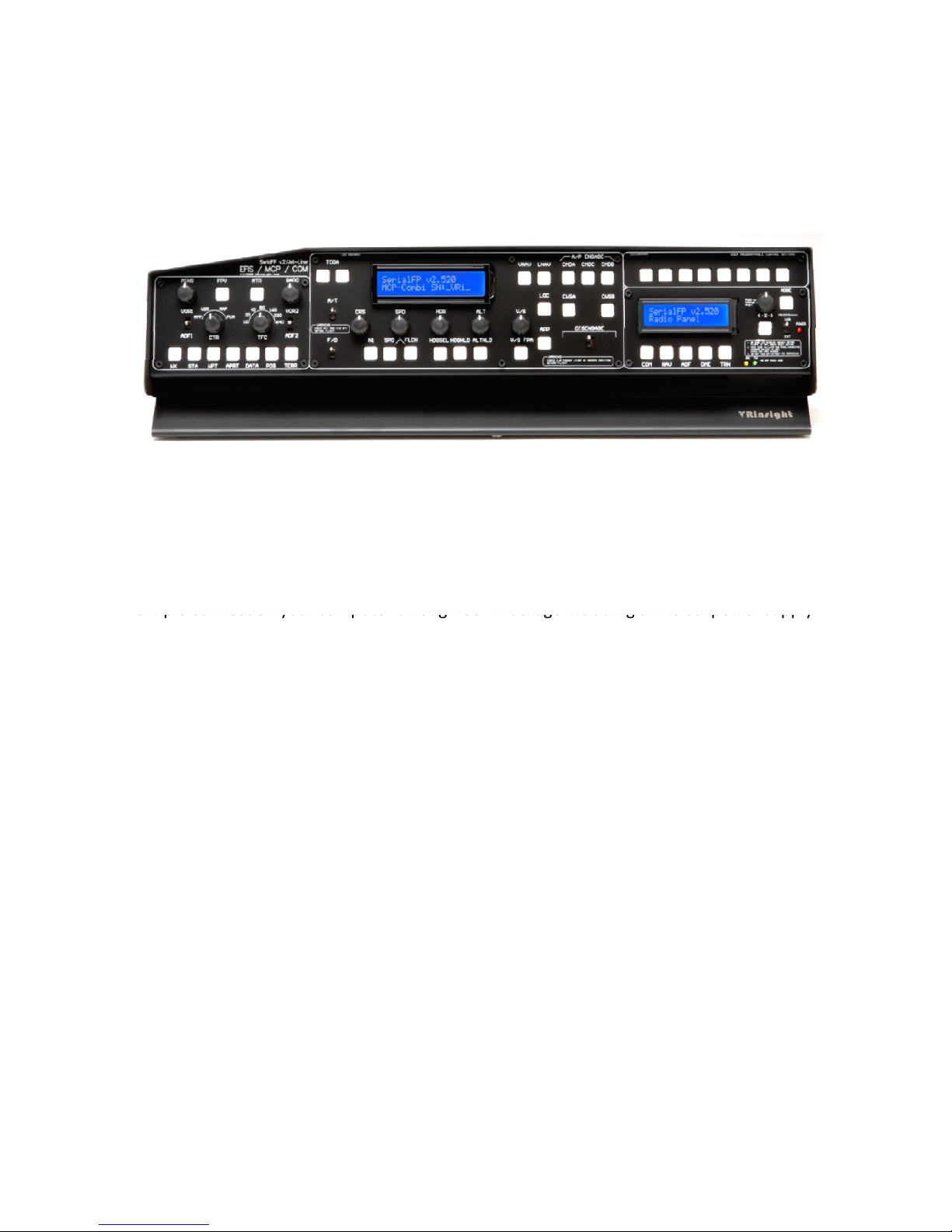
EFIS part
MCP part
The MCP combo panel features the following controls:
EFIS part :
- Toggle S/Ws for VOR1,2/ADF1,2 .
- Knob S/Ws for MINS, BARO, CTR ; ND mode selector and TFC.
- Push buttons for FPV, MTR, WXR, NAVAID, WPT, ARPT, DATA
- All buttons and rotary knobs are user-programmable
MCP part :
- 2 line character type LCD displaying SPD, HDG, ALT and Pitch & Bank
at Autopilot Status
- On/Off toggle S/Ws for F/D, A/T
- Thrust mode selection buttons: N1, SPD, FLCH
- Push buttons for HDG SEL & HOLD, ALT HOLD, V/S SEL, TOGA, CRZ,
VNAV, LNAV, CMDA, CMDB, CMDC, LOC, CWSA(Y/D), CWSB(BCRS),
APP
- On/Off toggle switch for DISENGAGE.
COM part
COM(Instrument Radio) and 8-User programmable control part :
- 2 line character type LCD displaying COM & NAVAID Frequencies,
DME distance, speed, VOR ID & CRS, Squawk code
- 5 push buttons for Instrument radio function selector
(COM, NAV, ADF, DME, TRANSPONDER)
- Rotary knob for NAVAID’s frequency change, CRS/OBS, Squawk Code
- TFR button for activating stand-by frequency
- 8 User programmable control buttons
4

Features
• Integrated unit with full radio stack function : EFIS part, MCP part, COM
part
• All necessary buttons, switches and LCD panel to input SPD, VOR, HDG
and all other functions for getting close to real flight.
• Offer actual flight circumstance via MCP combo panel with full control
complement
• Full metal cases
• One year warranty
Technical specifications
• USB interface type to computer
• External power requirement : DC 5V adaptor or USB power supply type to
MCP combo panel. We recommend using DC 5V adaptor.
• 50cm(W) x 14cm(H)
• 4Kg
Compatibility software
• Flight simulator 2004 / FSX by Microsoft
Operating software
• VRiSim
5

VRiSim Installation
When you connect MCP combo panel to your computer at first, your computer will detect it
With MCP combo panel, an “Install DVD” is included. When you insert it in DVD driver of your
computer, “VRinsight HTML” document will be shown. Then click “VRiSim” (operating
software) and install it at a proper folder.
“VRiSim” is the main operating software of VRinsight used for all VRinsight flight panels.
VRiSim software supports full functions of MCP combo panel and completely interfaced with
MSFS9 and MSFSX enables full simulation with simple connection with your computer
through USB.
Be sure that when installing VRiSim, “Install USB-Serial Driver” must be checked.
After installation, you can find “SeiralFP2” in “All programs” of “Start menu”.
USB Connection
The connection between MCP combo panel and your computer is made using a USB cable
that plugs into an USB port on your computer. If you want to use a USB hub, be sure that the USB
hub is USB 2.0 compliant. Otherwise it may cause a malfunction.
and will describe the process step by step.
Power Connection
Power supplying of MCP combo panel is done by universal power supply adaptor DC 5V
(Included in package) and/or USB port of your computer. Make sure that before trying to
operate MCP combo panel, you must confirm the USB connection first in order to prevent
malfunction.
Before trying to operate, be sure that LCD displaying is shown.
Run “VRiSim”
When you confirm all setup processes done; “VRiSim” installation, “USB connection” and
“Power connection”, you are ready to operate MCP combo panel.
Download & install “FSUIPC”
Refer to “Download & install FSUIPC” at “Download” part of www.vrinsight.com
FS 9 requires FSUIPC v3.80 or later. FSX requires FSUIPC v 4.26 or later.
6
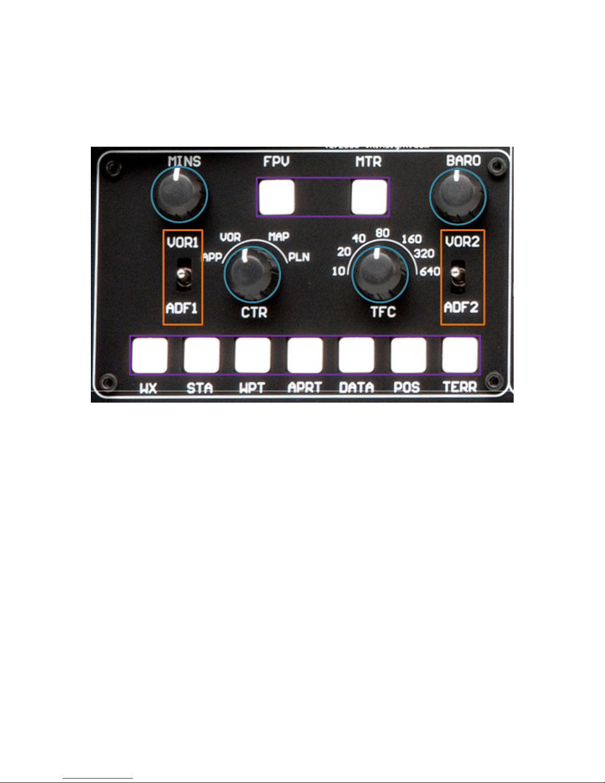
EFIS part controls explanation
EFIS (Electronic Flight Instrument System) : It is used to control the respective Primary
Flight Display (PFD) and Navigation Display (ND). EFIS panel includes controls for selecting
various modes and ranges on the ND as well as switches to display NAVAIDS, waypoint,
airports and etc. Two toggle S/Ws allow displaying of the left and right VOR and ADF
bearing pointer on the ND. Controls are available to set barometric altimeter settings for
displaying on the PFD.
•The functions of each button and knob can be differed from the explanation according to
the aircraft's implementation. Also, buttons and knobs are user programmable for another
functionality.
7
Toggle
APP, VOR, MAP, PLN.
S/W
L or R VOR / ADF switch : Select NAVAID between VOR or
ADF.
Rotate &
Push
MIN
S
BAR
O
CTR
Pushing : Resets or blanks PFD display
Rotating : Adjusts PFD radio or baro minimums altitude
Pushing : Displays preselected barometric setting
Rotating : Adjusts barometric reference
Pushing : Displays full compass rose for APP, VOR and
MAP modes. Subsequent pushing alternates between
expanded and centered displays
Rotating : Changes ND(Navigation Display) mode among
APP : Approach mode, displays ILS, localizer and glide
slop information in heading up format. Reference ILS
receiver, ILS frequency or identification, course and DME
VOR : VOR mode, displays VOR navigation information in
heading up format. Reference VOR receiver, VOR
frequency or identification, course and DME and
TO/FROM information
TFC
MAP : Map mode, displays FMC-generated route and
map information airplane position, heading and track in
tracking-up format. Displays waypoints, including the
active waypoint within the selected range. Also displays
VNAV deviation
PLN : Plan mode, displays a stationary true north-up route
depiction. Route may be reviewed selecting “STEP” at
using the CDU legs
Pushing : Displays TCAS information on the ND
Rotating : Selects the desired ND nautical miles range
scale
8
 Loading...