

Page 1
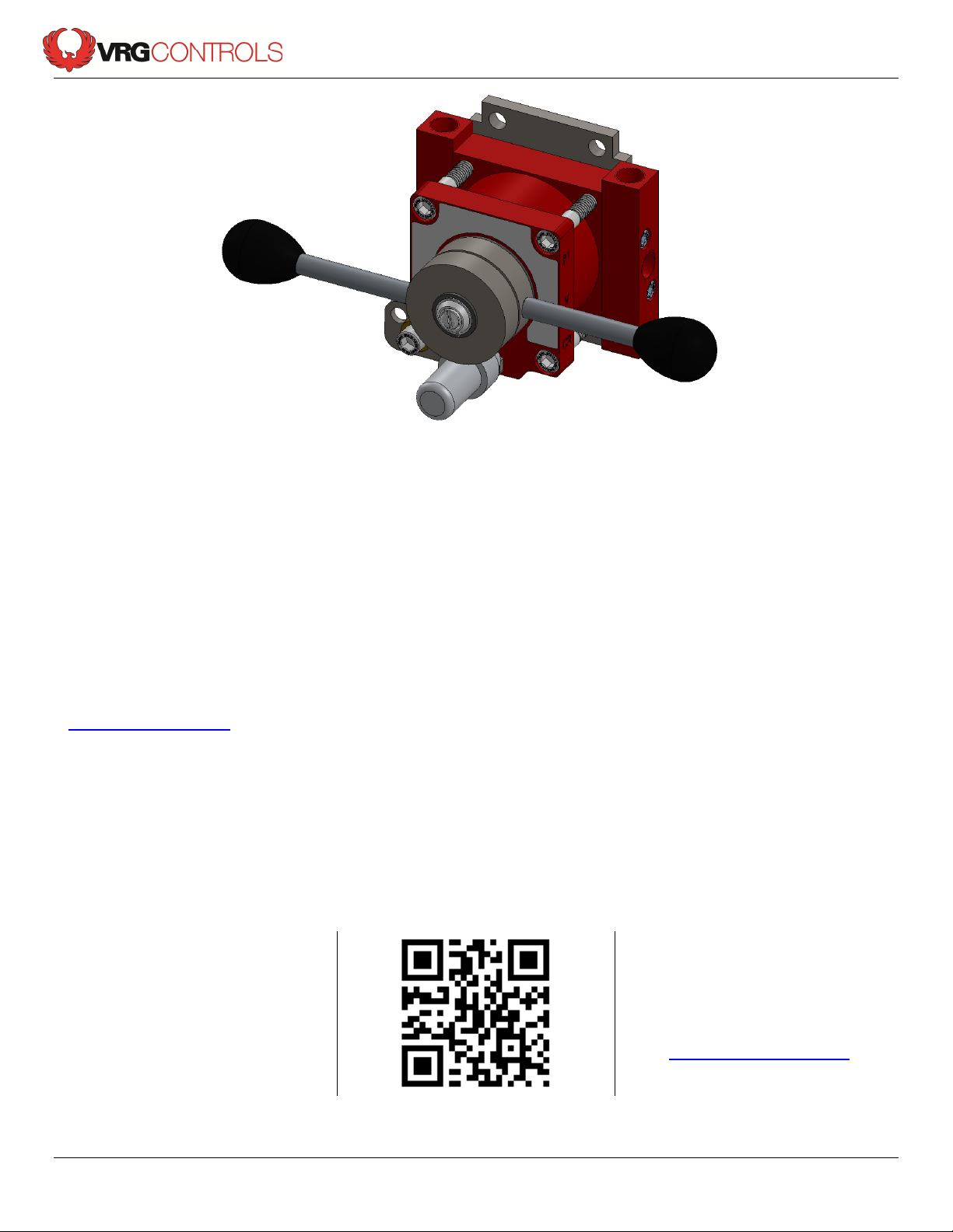
VPC Series Valve Pilot Controllers
Instruction Manual
Applicable Models:
VRG Controls, LLC
VMO Valve Manual Override
Instruction Manual
This Instruction Manual applies to the following VRG – Valve Manual Override Models. To confirm suitability
for additional models and/or components, please contact VRG Controls or view us online at
www.vrgcontrols.com.
VMO-150 VMO-250
VRG Controls, LLC Page 1 of 8 09 JUL 2013
Stay in Touch!
Scan the QR Code at right
for company information
and product updates
Our Address:
VRG Controls, LLC
Highland Park, Illinois USA
www.vrgcontrols.com
eMail: [email protected]
Page 2
VPC Series Valve Pilot Controllers
Instruction Manual
VPC Instruction Manual Table of Contents
Section Description Page
1 Scope of Manual 3
2 Technical Assistance 3
3 Applicable Models 3
4 Description 3
5 VMO Valve Manual Override Technical Specifications 4
6 Component and Port Identification 5
7 Dimensional Drawings 5
8 VMO Operation Instructions 6
9 VMO Application Schematics 7
VRG Controls, LLC Page 2 of 8 09 JUL 2013
Page 3

VPC Series Valve Pilot Controllers
Instruction Manual
Scope of Manual:
This Instruction Manual provides instructions for installation and operation of VRG Controls VMO Valve Manual Overrides.
This product is typically utilized in conjunction with control valves, pneumatic actuators and a variety of other ancillary
devices and accessories. For information on products other than those manufactured by VRG Controls, please consult the
appropriate manufacturer.
Warning:
VMO Valve Manual Overrides utilize high pressure flammable natural gas or other pneumatic supply as part of
their standard operation. Improper installation, operation, maintenance and adjustment of these devices can
result in property damage, personal injury or death. Only those qualified through training should install, operate, maintain
or adjust this product. The VMO Valve Manual Override IS NOT A FIELD SERVICABLE DEVICE AND SHOULD NOT BE
DISASSEMBLED. Contact your local VRG Controls sales representative or VRG Controls direct for additional information
or assistance.
Technical Assistance:
For technical assistance with VRG products, please contact your local VRG Controls sales representative or VRG
Controls direct. In order to facilitate technical assistance, we strongly recommend that obtain the MODEL NUMBER and
SERIAL NUMBER where applicable of the product for which you require assistance prior to contact us.
Our Address:
Stay in Touch!
Scan the QR Code at right
for company information
and product updates
We recommend that you record the MODEL NUMBER and SERIAL NUMBER where applicable of all VRG Products
installed at each application location in the table below for future reference.
Applicable Models:
This Instruction Manual applies to the following VRG – Valve Manual Override Models. To confirm suitability for
additional models and/or components, please contact VRG Controls or view us online at www.vrgcontrols.com
VRG Controls, LLC
467 Ridge Road
Highland Park, Illinois USA
www.vrgcontrols.com
eMail: [email protected]
VMO-150 VMO-250
Description:
The VMO Valve Manual Override is the ideal device to provide manual operation of pneumatically actuated
ON-OFF Type Remote Control Valves (RCV’s) and Regulating Control Valves. The VMO allows the operator to
override the primary control instrumentation and position the actuated valve in open, closed or any intermediate
positions. VMO Series Valve Manual Overrides are the perfect device for valve maintenance, commissioning or
emergency operation. All units are provided with standard locking provision to prevent unauthorized operation
and facilitate lockout / tagout procedures.
VRG Controls, LLC Page 3 of 8 09 JUL 2013
Page 4
VPC Series Valve Pilot Controllers
Instruction Manual
Applications:
The VMO Valve Manual Override is designed to provide manual operation of pneumatically actuated
ON-OFF Type Remote Control Valves (RCV’s) and Regulating Control Valves. The VMO may be installed in conjunction
with a number of different PNEUMATIC ACTUATOR and CONTROL INSTRUMENTATION configurations. A list of typical
compatible actuator and instrumentation may be found below. We recommend that you contact your local VRG Controls
sales representative or VRG Controls direct for application assistance.
Compatible Actuator Types Compatible Instrumentation
• Compatible Actuator Types
• Double Acting Piston
• Spring Return Piston
• Scotch Yoke Style
• Crank Arm Style
• Spring & Diaphragm Rotary
• Spring & Diaphragm Linear
• Rotary Vain
• Rack & Pinion
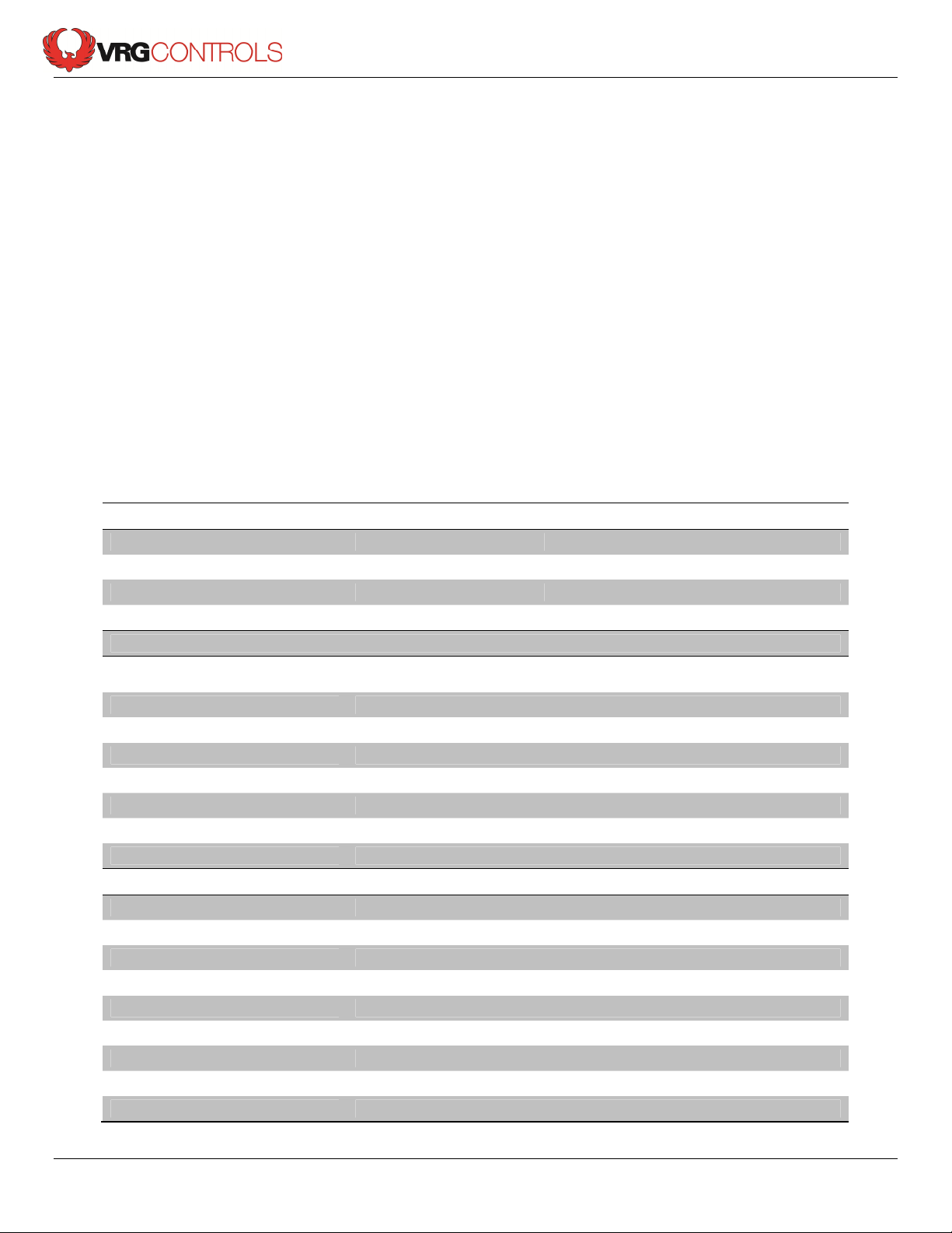
VMO Valve Manual Override Technical Specifications
• Pneumatic Valve Positioners
• Electro-Pneumatic Positioners
• Valve Pilot Controllers
• Digital Valve Controllers
• Solenoid Valves
• Pilot-Operated Valves
• VPC Valve Pilot Controllers
Available Models
VMO Model P
VMO-150
VMO-250
Where: P
Differential
= P
Supply
- P
Discharge
400 psig 150 psid
400 psig 250 psid
Max. P
Supply
Differential
Max.
Specifications
Type
Ports
Flow Capacity
Weight
Mounting
Dimensions
Action
Options
Rotary, lapped disc, 5-position/6-way manually operated valve with
manifolded porting assembly
¼ in. FNPT (6) Manifolded to Body
Cv= 0.40
8.0 Lbs. (3.6 kg)
Back Face Mount
See Figure Above
Double Acting or Single Acting in same device
Limit Switches to indicate AUTO or MANUAL operation
Materials
Coating
Body
Bolting
Body O-Rings
Handle (Knob)
Handle (Shaft)
Internal Discs
Manifolds
Mounting Plate
VRG Controls, LLC Page 4 of 8 09 JUL 2013
Red Polyurethane Topcoat & Zinc Primer over Chemical Cleaning
Carbon Steel
316 Stainless Steel SHCS
Buna-N
Impact Resistant Black Phenolic
304 Stainless Steel
Precision Lapped Carbon Steel
304 Stainless Steel
304 Stainless Steel
Page 5
Instruction Manual
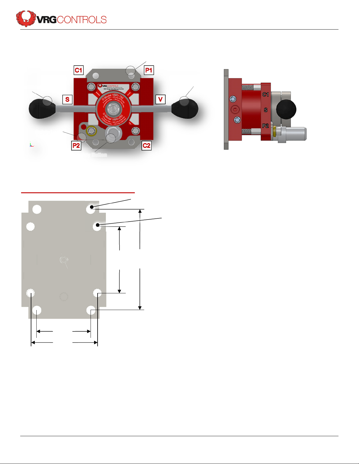
Component and Port Identification:
VPC Series Valve Pilot Controllers
Auto/Manual Handle
Safety Lock
Safety Button
VMO Backplate Dimensions (¼ in Thick):
VMO Mounting Backplate
Position Handle
11
/32 in Dia. X4 Surface Mount Holes
11
/32 in Dia. X4 VMO Mount Holes
2.0 in
2.474 in
2.474 in
2.750 in
VRG Controls, LLC Page 5 of 8 09 JUL 2013
Page 6
VPC Series Valve Pilot Controllers
Instruction Manual
1
2
3
1
2
3
5
4
1
2
3
1
3
2
5
CLOSE
OPEN
3
1
2
1
4
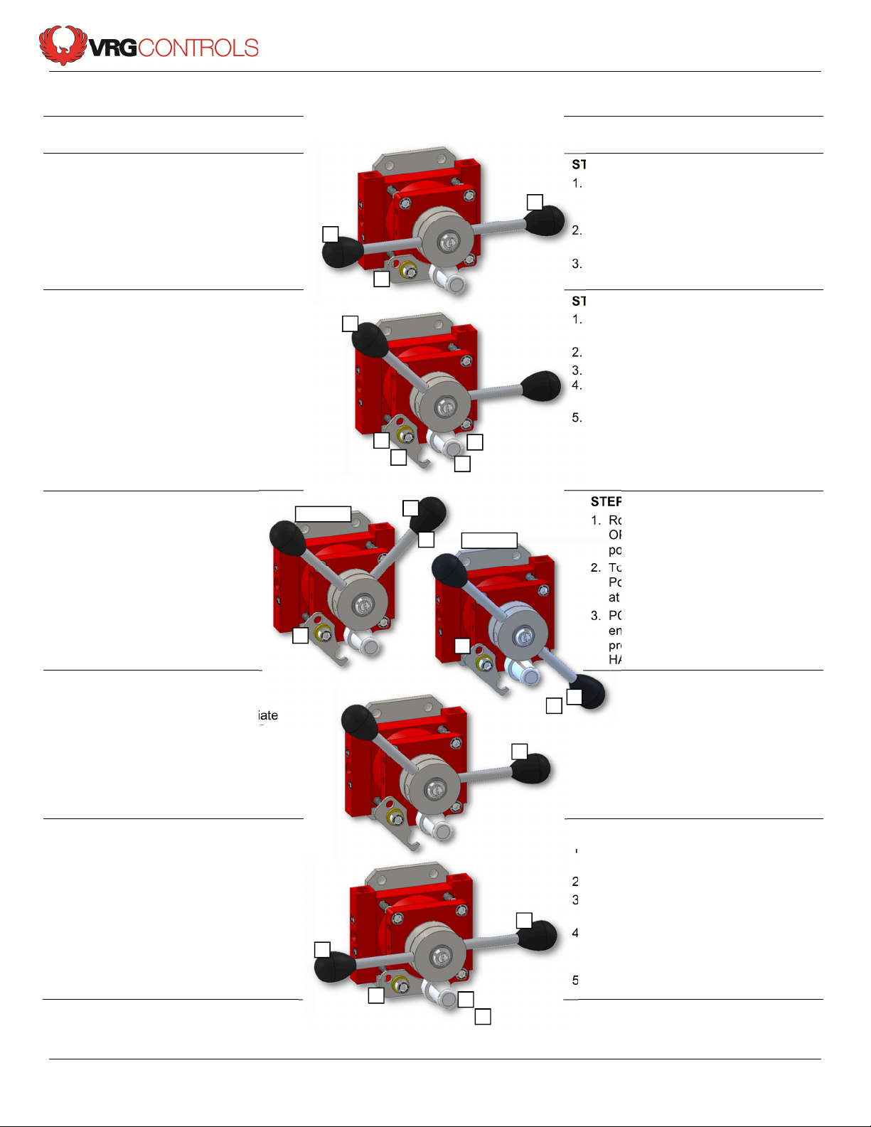
VMO Operation Instructions
How to CLOSE Valve Using VMO Valve
Manual Override
STEP 1 – START AT AUTO MODE
1. Valve is in AUTOMATIC MODE with
AUTO/MANUAL HANDLE at AUTO (A)
Position.
2. POSITION HANDLE is at NEUTRAL (N)
Position.
3. SAFETY LOCK is engaged.
STEP 2- ENGAGE MANUAL MODE
1. Remove padlock from SAFETY LOCK if
applicable.
2. Rotate SAFETY LOCK to disengage
3. Depress SAFETY BUTTON
4. Rotate AUTO/MANUAL HANDLE up to
MANUAL (M) Position.
5. Ensure that SAFETY BUTTON releases
once AUTO/MANUAL handle is at
MANUAL (M) mode to allow movement
of POSITIONING HANDLE.
STEP 3- MOVE TO CLOSE
1. Rotate POSITION HANDLE up to
CLOSE (C) position valve to
desired position.
2. To move valve to FULL CLOSED
Position, leave POSITION
HANDLE at CLOSE (C) position.
3. POSITION HANDLE LOCK may
be engaged for “lock out/tag out”
procedure. Optional POSITION
HANDLE LOCK not shown.
STEP 4- STOP AT INTERMEDIATE
POSITION
1. Valve may be stopped in intermediate
position by returning POSITIONING
HANDLE to NEUTRAL (N) position.
How to OPEN Valve Using VMO Valve
Manual Override
STEP 1 – START AT AUTO MODE
1. Valve is in AUTOMATIC MODE with
AUTO/MANUAL HANDLE at AUTO (A)
Position.
2. POSITION HANDLE is at NEUTRAL
(N) Position.
3. SAFETY LOCK is engaged.
STEP 2- ENGAGE MANUAL MODE
1. Remove padlock from SAFETY LOCK if
applicable.
2. Rotate SAFETY LOCK to disengage
3. Depress SAFETY BUTTON
4. Rotate AUTO/MANUAL HANDLE up to
MANUAL (M) Position.
5. Ensure that SAFETY BUTTON releases
once AUTO/MANUAL handle is at
MANUAL (M) mode to allow movement
of POSITIONING HANDLE.
STEP 3- MOVE TO OPEN
1. Rotate POSITION HANDLE up to
OPEN (O) position valve to desired
position.
2. To move valve to FULL OPEN
Position, leave POSITION HANDLE
at OPEN (O) position.
3. POSITION HANDLE LOCK may be
engaged for “lock out/tag out”
procedure. Optional POSITION
HANDLE LOCK not shown.
STEP 4- STOP AT
INTERMEDIATE POSITION
1. Valve may be stopped in
intermediate position by
returning POSITIONING
HANDLE to NEUTRAL (N)
position.
STEP 5- RETURN TO AUTO MODE
1. Move POSITIONING HANDLE to
NEUTRAL (N) Position
2. Depress SAFETY BUTTON
3. Rotate AUTO/MANUAL HANDLE to
AUTO (A) Position.
4. Ensure that SAFETY BUTTON releases
once AUTO/MANUAL handle is at
AUTO (A) mode
5. Engage SAFETY LOCK if applicable
VRG Controls, LLC Page 6 of 8 09 JUL 2013
STEP 5- RETURN TO AUTO MODE
1. Move POSITIONING HANDLE to
NEUTRAL (N) Position
2. Depress SAFETY BUTTON
3. Rotate AUTO/MANUAL HANDLE to
AUTO (A) Position.
4. Ensure that SAFETY BUTTON releases
once AUTO/MANUAL handle is at
AUTO (A) mode
5. Engage SAFETY LOCK if applicable
Page 7
VPC Series Valve Pilot Controllers
Instruction Manual
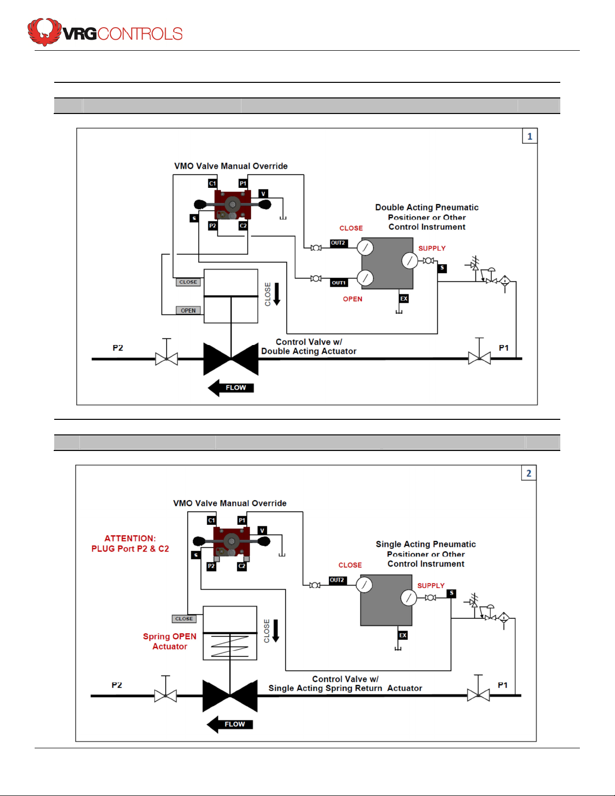
VMO Valve Manual Override Installation Schematics
No. VMO Actuator Mode Actuator Failure Mode Page
1
VMO-150 or VMO-250 Double Acting Double Acting 7
No. VMO Actuator Mode Actuator Failure Mode Page
2
VMO-150 or VMO-250 Single Acting Spring Return Spring Open 7
VRG Controls, LLC Page 7 of 8 09 JUL 2013
Page 8

VPC Series Valve Pilot Controllers
Instruction Manual
VMO Valve Manual Override Installation Schematics (Cont’d.)
No. VMO Actuator Mode Actuator Failure Mode Page
3
VMO-150 or VMO-250 Single Acting Spring Return Spring Close 8
Stay in Touch!
Scan the QR Code at right
for company information
and product updates
Our Address:
VRG Controls, LLC
Highland Park, Illinois USA
www.vrgcontrols.com
eMail: [email protected]
VRG Controls, LLC Page 8 of 8 09 JUL 2013
 Loading...