

VR Avionics Walter M601 Installation & Operation Manual

TSLM
for
Walter M601
Engines
OPERATIONAL &
INSTALL MANUAL
Updated: 29 June 2016
Copyright 2016 by VR Avionics

TSLM - M601 Operational & Install Manual
© 2016 VR Avionics Inc.
All rights reserved.
This User and Installation Guide and the information contained herein is the proprietary data of VR
Avionics. No part of this manual may be reproduced, copied, transmitted, disseminated or stored in
any storage medium, for any purpose without the express written permission of VR Avionics, Inc.
VR Avionics hereby grants permission to download a single copy of this manual and of any
revision to this manual onto a hard drive or other electronic storage medium to be viewed for
personal use, provided that such electronic or printed copy of this manual or revision must contain
the complete text of this copyright notice and provided further that any unauthorized commercial
distribution of this manual or any revision hereto is strictly prohibited. Information in this document
is subject to change without notice. VR Avionics reserves the right to change or improve its
products and to make changes in the content without obligation to notify any person or
organization of such changes. Visit the VR Avionics website (www.vravionics.com) for current
updates and supplemental information concerning the use and operation of this and other VR
Avionics products.
VR Avionics
www.vravionics.com
06/29/16 © 2016 VR Avionics page 2 of 33

TSLM - M601 Operational & Install Manual
Contents
Introduction.......................................................................................................................................5
System Options...............................................................................................................................5
Retrofit to existing systems.............................................................................................................5
TSLM versions................................................................................................................................5
Operation...........................................................................................................................................6
Introduction.....................................................................................................................................6
Power-up (Master ON)....................................................................................................................6
Initiating a Start...............................................................................................................................6
Initiating a Run ...............................................................................................................................7
Automatic Protection Limiting.........................................................................................................8
Start Limiting...............................................................................................................................8
Beta & Reverse Propeller Limiting..............................................................................................8
Anti-Flameout Operation (AFO)......................................................................................................8
Determining Engine State...............................................................................................................8
Parameter Exceeds........................................................................................................................9
Required Actions........................................................................................................................9
TSLM Light Codes..........................................................................................................................9
Operational Check Lists and Codes.............................................................................................10
Electrical & Mechanical Specifications.........................................................................................11
Dimensions (SN 7001 and later)...................................................................................................11
Dimensions (SN 5001 – 6200)......................................................................................................12
RS232 Data Interface (SN 5001 – 6200)......................................................................................12
Installation.......................................................................................................................................13
Tools and Equipment....................................................................................................................13
Electrical Installation.....................................................................................................................14
Power and Ground........................................................................................................................15
Ignition Circuit...............................................................................................................................16
Start/Run Selection.......................................................................................................................17
Start Contactor..............................................................................................................................17
Start Interrupter Valve...................................................................................................................18
Limiting (EHT) Circuit....................................................................................................................19
TSLM Status Light........................................................................................................................20
Exceed Light.................................................................................................................................20
Voltage Sensing............................................................................................................................21
Gas Generator Speed Sensing (N1).............................................................................................21
Propeller Speed Sensing (N2)......................................................................................................21
Inter Turbine Temperature Sensing (ITT).....................................................................................22
Beta Switch Sensing.....................................................................................................................22
Torque and Oil Pressure Sensing (optional)................................................................................23
Oil Temperature Sensing (optional)..............................................................................................24
TSLM Pin Definitions....................................................................................................................25
Configuration..................................................................................................................................26
Introduction...................................................................................................................................26
Configuration Settings..................................................................................................................26
History Recorded (bytes)..........................................................................................................26
Start Cycles..............................................................................................................................26
Flight Hours..............................................................................................................................26
Upper ITT Exceeds...................................................................................................................26
Lower ITT Exceeds...................................................................................................................26
N1 Exceeds .............................................................................................................................26
N2 Exceeds .............................................................................................................................26
Torque Exceeds .......................................................................................................................27
Max. Unit Temperature ºC .......................................................................................................27
Min. Unit Temperature ºC ........................................................................................................27
Last Attempted Start Time (seconds) ......................................................................................27
06/29/16 © 2016 VR Avionics page 3 of 33

TSLM - M601 Operational & Install Manual
Last Attempted Start Min Voltage (V) ......................................................................................27
Last Attempted Start Max ITT (ºC) ..........................................................................................27
Last Attempted Start EHT Resistance (Ohms) ........................................................................27
ITT Calibration .........................................................................................................................27
Voltage Calibration ..................................................................................................................27
Torque Span Calibration ..........................................................................................................27
Torque Offset Calibration ........................................................................................................27
Oil Pressure Span Calibration .................................................................................................27
Oil Pressure Offset Calibration ................................................................................................27
Oil Temperature Span Calibration ...........................................................................................27
Oil Temperature Offset Calibration ..........................................................................................28
Alternative Interrupter Activation .............................................................................................28
Enable Oil-Temperature Measurement....................................................................................28
Torque sensor is 200 psi type..................................................................................................28
Force a Start sequence when double-clicking Start Button .....................................................28
Walter Engine Type (0=M601D, 1=M601E-11, 2=M601E-11A) ..............................................28
Start ITT Control Setting ..........................................................................................................28
History Logs Operations...............................................................................................................28
History retrieval.........................................................................................................................28
History clearance......................................................................................................................28
Viewing the history....................................................................................................................28
Diagnostic Tests...........................................................................................................................29
Ignition check............................................................................................................................29
Interrupter check...........................................................................................................................29
EHT valve check...........................................................................................................................29
Exceed light check....................................................................................................................29
SetView Software ...........................................................................................................................30
Introduction...................................................................................................................................30
System Requirements..................................................................................................................30
SetView download and Installation...............................................................................................30
Using SetView...............................................................................................................................30
Viewing and recording parameters...........................................................................................31
Synchronizing with the system.................................................................................................31
Sharing files via email...............................................................................................................31
Adjusting the configuration.......................................................................................................32
Opening and viewing history files.............................................................................................33
Diagnostic test and troubleshooting.........................................................................................33
06/29/16 © 2016 VR Avionics page 4 of 33
TSLM - M601 Operational & Install Manual
Introduction
System Options
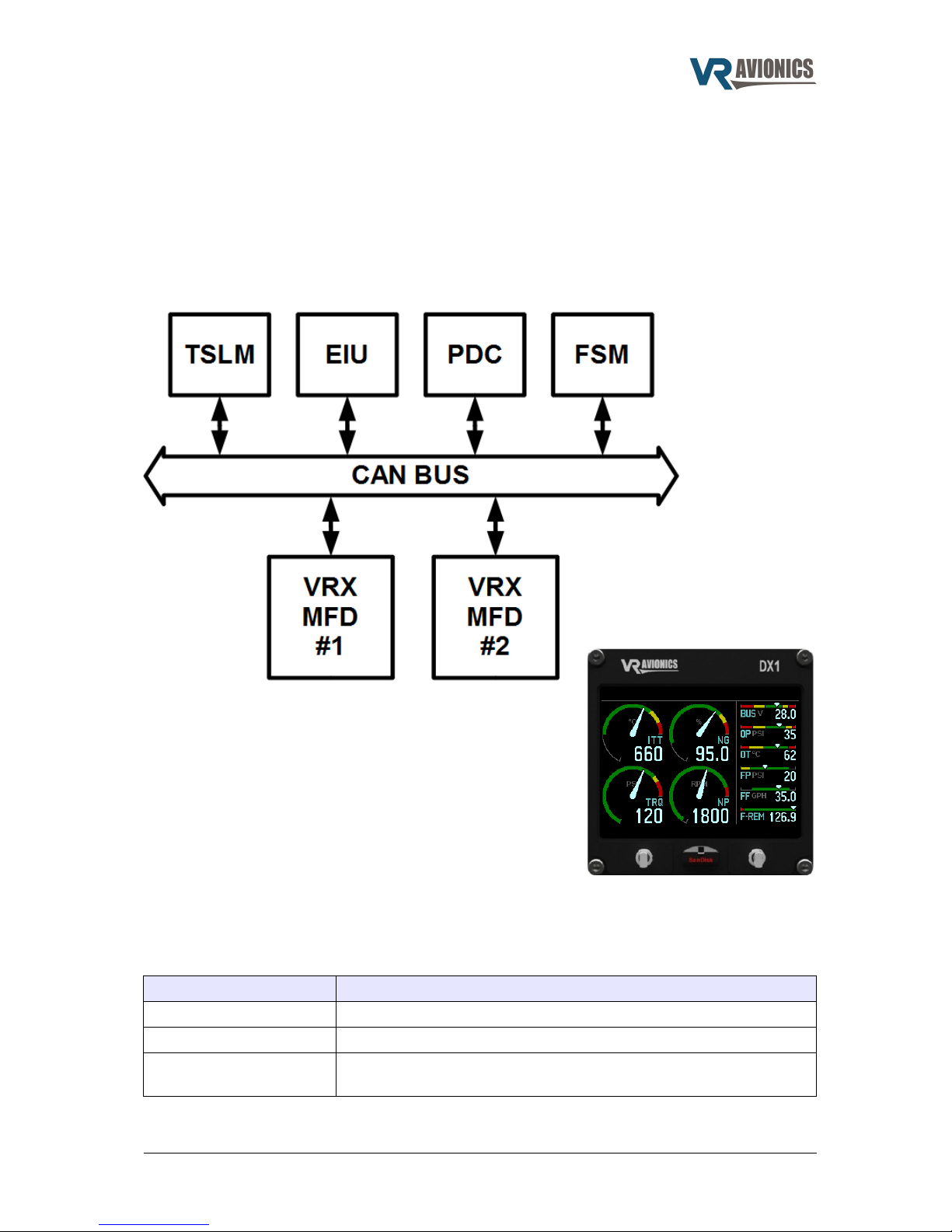
This manual describes the installation and operation of the Turbine Start Limit & Monitor (TSLM)
from VR Avionics when used with a Walter/GE M601 engine. The TSLM is a unit (black box) which
can function standalone or with other units (black boxes) from VR Avionics as shown below. This
manual is dedicated to the TSLM, so when planning to install further units the user must also
include the manuals of these other units. For example, should you plan to use one or more VRX
multi-function displays, you need to read the VRX-M601 Operational & Installation manual.
Retrofit to existing systems
The TSLM unit can be easily retrofitted to an already
existing aircraft system. Since it is remote mount, it will have
little to no impact on your current instrument panel if start
control and limiting is all you require. You can however
choose to add a VRX multi-function display (shown here) for
the added monitoring it provides, in which case you need to
make a little space for this on your panel.
TSLM versions
A few versions of the TSLM have been produced over the years. Later versions have remained
backward compatible with earlier ones by retaining the connector and pin-outs for the most part.
The following table lists the differences other than normal general performance improvements of
the various versions as referenced by their serial numbers:
Serial number range Differences
3001 - 4100 First Generation
5001 - 6200 Oil-temperature measurement added
7001 and later New more compact enclosure
No serial port connector
Units with serial numbers 5001 and up are handled in this manual.
06/29/16 © 2016 VR Avionics page 5 of 33

TSLM - M601 Operational & Install Manual
Operation
Introduction
The following sections describe the working of the TSLM (firmware version 3.1 or later) in detail.
Near the end of this chapter we provide the various checklists and error codes on one page for
your convenience.
Power-up (Master ON)
When first the TSLM is powered it turns on the TSLM light for about 2 seconds while it does a selfcheck. If everything checks out the TSLM light is turned off. If a problem or concern is detected the
TSLM light indicates as follows:
Problem or Concern TSLM light indication
EHT Error:
The EHT valve is being powered externally from the
TSLM due to possible wiring problem
4 blinks.. pause.. 4 blinks.. pause, etc
Memory Warning:
The TSLM memory used for recording start and
exceed graphs has reached the 90% mark. You may
want to retrieve this history and clear the TSLM's
memory.
7 blinks (directly after power-up)
TSLM Internal Fault:
The TSLM has failed the self-check and needs to be
serviced.
Solidly on or slowly flashing (no code)
Initiating a Start
By depressing the START button you initiate a start sequence. The TSLM performs pre-start
checks first unless commanded to bypass them (see later). It checks that the ITT is connected
properly and reads below 200ºC, that the bus voltage is at least 20 volt and that the EHT is
detected electrically. These checks have been included for safer starting and if one fails the TSLM
will decline the start and report the cause via the TSLM light as follows:
Cause of Error TSLM light indication
ITT Error:
ITT is above 200ºC or not connected properly. If
above 200ºC you may want to do a RUN to cool it
down before attempting another start.
2 blinks.. pause.. 2 blinks.. pause, etc.
Voltage Error:
The bus voltage is too low for safe starting.
3 blinks.. pause.. 3 blinks.. pause, etc.
EHT Error:
Access by the TSLM to the EHT valve could not be
confirmed electrically. The reason could be that the
limiter enable/disable switch is not in the correct
position.
4 blinks.. pause.. 4 blinks.. pause, etc
The pre-start checks can be bypassed by double-clicking the START button. The “double-click
start override” setting must be enabled in the TSLM configuration for this to work.
06/29/16 © 2016 VR Avionics page 6 of 33

TSLM - M601 Operational & Install Manual
If one of the pre-start checks failed, you should correct the cause before trying again. To
acknowledge or reset the error code on the TSLM light you can press the START or RUN button
for 1 second. The TSLM light shall stop flashing and you are ready to issue another start.
If all the pre-start checks pass, the TSLM will activate the start sequence by engaging the starter,
turning on the ignition and sequencing the fuel to the torch igniters. You should be able to hear the
starter/generator wind up and the igniters producing sparks. From the moment the starter engages
there are 10 seconds reserved for light-off. Light-off is where the main fuel in the combustion
chamber ignites and can clearly be heard and seen in the ITT rising sharply. In case light-off does
not occur within the 10 seconds (which implies some problem), the TSLM will turn off the ignition
and stop the fuel to the torch igniters, but continue spinning the engine for 10 more seconds.
If this happens the pilot must close the fuel (shut-off valve lever to closed) just after the first 10
second period have expired. With the engine spinning for the next 10 seconds or so, closing the
fuel will purge fuel vapors from the combustion chamber.
If the engine lights off before the first 10 second period expired (as would normally happen), the
TSLM will sense this and immediately start controlling the rise in ITT and the absolute ITT value as
needed by activating the EHT valve. Both the TSLM light and the EHT light (if fitted) will turn on
when the EHT is activated by the TSLM during the start.
If the ITT leads (from the thermocouples) is connected the wrong way around (maybe after a
service) or become disconnected in some way that would only become apparent after light-off, the
TSLM will sense this and immediately turn on the EXCEED light. Since the TSLM can no longer
measure the ITT accurately in this condition, the pilot needs to abort the start by cutting fuel as
earlier mentioned to avoid possibly damaging the turbine. The starter will remain active for another
10 seconds so that fuel can again be purged from the combustion chamber.
The EXCEED light will also be turned on when the ITT increases to over 700ºC. The TSLM should
be able to control the ITT to below this temperature. If it is unable to, this would imply some major
problem – for example unintended isolating valve activation, dead batteries, or fuel control unit
problems. An abort of the start is recommended in this case.
When the compressor reaches idle speed (above 50%), the starter, ignition and fuel to the torch
igniters will be turned off. Otherwise these devices will timeout 20 seconds after light-off was
detected.
See also Determining Engine State.
Initiating a Run
A run operation purges possible fuel vapors inside the combustion chamber. If your ITT is above
200ºC performing a run will cool down the turbine temperature by forcing new air through the
engine.
By depressing the RUN button you initiate a RUN / MOTOR sequence. The TSLM will turn on the
starter for 8 seconds to spin the engine. After the 8 seconds, the starter is turned off. The TSLM
will monitor the N1 signal and alert you after the run if no signal was detected from the N1 tachgenerator sensor by pulsing the TSLM light as follows:
Caution TSLM light indication
N1 Error:
While conducting the run the TSLM did not detect any
signal from the N1 sensors. A signal should have
been detected. Check wiring.
5 blinks.. pause.. 5 blinks.. pause, etc
If you get the above warning, check your wiring to rectify this. See also Determining Engine State.
06/29/16 © 2016 VR Avionics page 7 of 33

TSLM - M601 Operational & Install Manual
Automatic Protection Limiting
The TSLM provides automatic engine limiting when it restricts fuel to the engine by activating the
EHT valve. The EHT light (if installed) will come ON whenever limiting is performed. Limiting is
restricted to only the start and beta-propeller speed limiting. Limiting may also be disabled, by an
external limiter enable / disable switch (see page 19 for its electrical circuit).
Start Limiting
During the start process the engine’s temperature (ITT) can be exceeded – more so when it is
started without any form of limiting (no activation of the EHT). The amount of limiting required vary
according to conditions such as outside air temperature, altitude, battery charge and initial ITT. The
TSLM utilizes an algorithm to control both the rate of rise and the absolute value of the inter-turbine
temperature (ITT).
If you have forgotten the limiter enable / disable switch (if installed) in the disable position when
initiating a start attempt, the TSLM's pre-start checks will detect it, decline the start attempt and
inform you via the TSLM light as to the problem. See the section on initiating a start for more.
Beta & Reverse Propeller Limiting
To prevent a propeller exceed in Beta mode as well as to ensure effective reverse thrust
application, the TSLM will limit the propeller speed (N2) while in BETA mode. The TSLM knows the
propeller is in beta mode by sensing the BETA micro-switch.
Anti-Flameout Operation (AFO)
In anti-flameout operation the igniters and ignition fuel valves are continuously activated as a
precautionary measure against engine flameout. This mode is manually activated by the pilot when
the engine has already been started (is running) by depressing the START switch for at least one
second before releasing it. The TSLM status light will light up to indicate that the AFO mode has
been entered. To deactivate this mode in-flight, the pilot depresses the RUN switch for at least one
second before releasing it. The TSLM status light should go out indicating the anti-flameout mode
has been exited. See also Determining Engine State.
Determining Engine State
The TSLM mainly uses the N1 (NG) parameter to determine whether the engine is running or notrunning (above 50% N1 means running and below means not-running). This engine state is
important since it impacts the start-run switch functionality. If not-running the start-run switch(es)
initiate start and run sequences, while if the engine is running the switch(es) activate and
deactivate anti-flameout operation (AFO). This is why proper N1 wiring and signaling to the TSLM
is emphasized and why we have a dedicated TSLM light code for N1 error. The TSLM has an
alternative to determine engine state if for example N1 become disconnected or the tach-generator
ceases to provide an alternating signal. In this alternative (where N1 will read zero) both the ITT
and N2 parameters need to be above 400 (400 °C ITT and 400 rpm N2) for the engine state to be
considered as running.
06/29/16 © 2016 VR Avionics page 8 of 33
TSLM - M601 Operational & Install Manual
Parameter Exceeds
Should any of the engine parameters go over their maximum limits the EXCEED light (if installed)
will come ON for the duration of the exceed. During this time all relevant parameters gets recorded
versus time and a dedicated counter increments within the TSLM. This information can be viewed
in the Configuration and History sections of the SetView software.
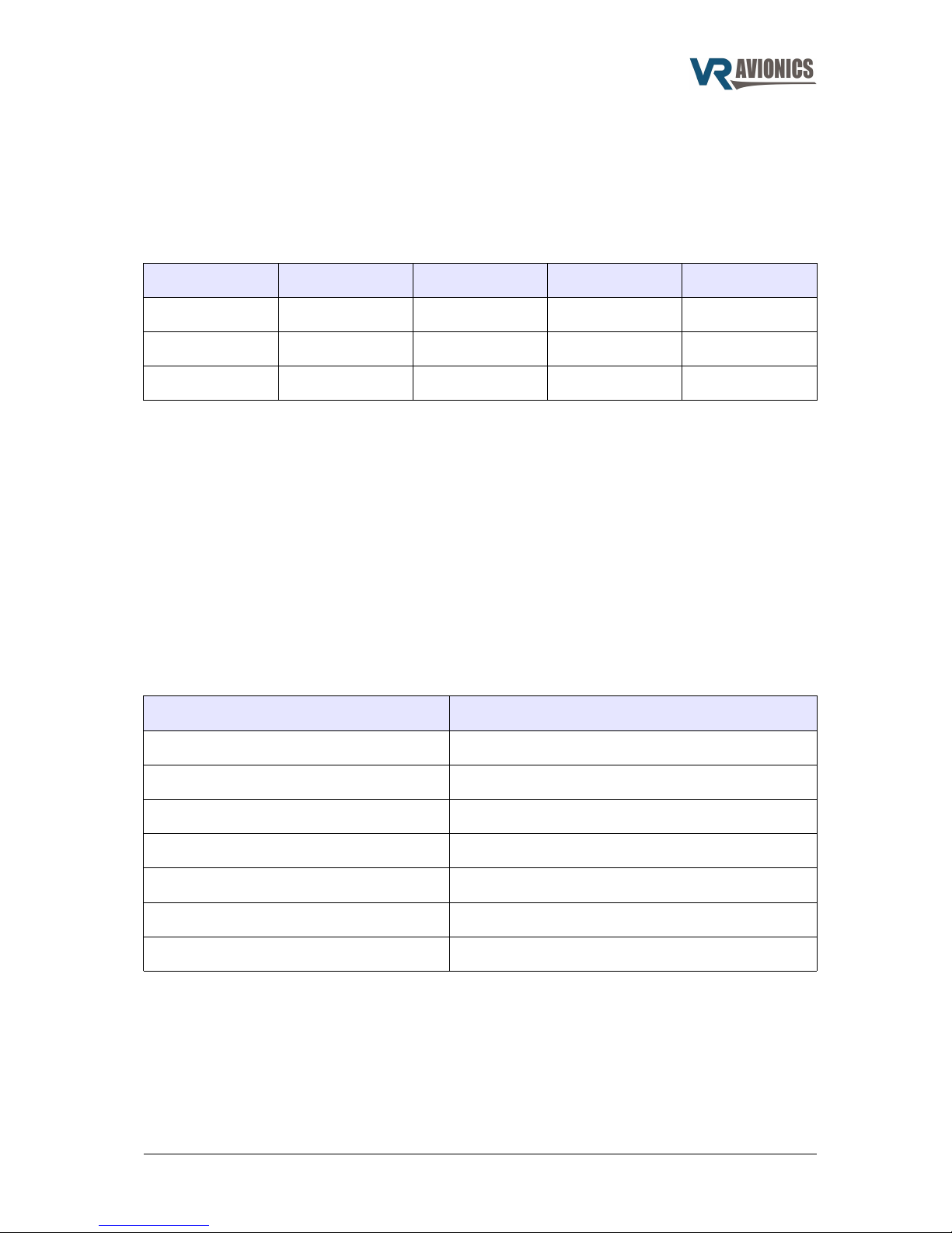
Parameter exceeds (maximum values) are according to the type of M601 engine used:
Engine Type Max. ITT Max. N1 Max. N2 Max. Torque
M601D 735 °C 100.00% 2080 RPM 132 psi
M601E-11 735 °C 100.00% 2080 RPM 145 psi (106%)
M601E-11A 710 °C 98.50% 1950 RPM 134 psi (98%)
Make sure that you set the “Engine Type” configuration property to the appropriate model engine
you are using (see page 28).
Required Actions
Should the EXCEED light have come on during flight, you can retrieve and analyze the time-graph
recorded within the TSLM to decide on what action to take next. Required actions vary from no
action to returning the engine to an overhaul facility for inspection/repair. With the graph you will
not only identify the parameter exceeded, but obtain both the maximum it reached as well as the
time it spent above the maximum limit. With this you will be able to look-up the required action you
need to take using the engine's manual, or asking a qualified person.
TSLM Light Codes
The TSLM light provides feedback to the pilot concerning the system. The light will blink a certain
pattern to report any problem to the pilot. The following table shows the codes:
Problem TSLM light indication
ITT Error 2 blinks.. pause.. 2 blinks.. pause, etc
Voltage Error 3 blinks.. pause.. 3 blinks.. pause, etc
EHT Error 4 blinks.. pause.. 4 blinks.. pause, etc
N1 Error 5 blinks.. pause.. 5 blinks.. pause, etc
ISOL Error 6 blinks.. pause.. 6 blinks.. pause, etc
Memory Warning 7 blinks.. pause.. 7 blinks.. pause, etc
TSLM Internal Error Solid ON, or slowly flashing
See also the sections that describes initiating a start and a run.
Acknowledging the TSLM light Indication:
An error code can be acknowledged and reset by holding either the start or run button / switch
down for at least 1 second. The TSLM light will then stop blinking, which will indicate that the TSLM
is now ready to accept new commands from the pilot (start, run, etc.).
06/29/16 © 2016 VR Avionics page 9 of 33

TSLM - M601 Operational & Install Manual
Operational Check Lists and Codes
START:
1. Power ON
2. Inverter on if necessary
3. Fuel ON
4. Fuel pump(s) ON
5. Condition lever forward to OPEN (detent)
6. Propeller in feather position
7. Throttle in IDLE position
8. Ensure ISOL valve is OFF (normal position)
9. Ensure Limiter Enable switch (if installed) is ON
(normal position)
10. Press START. Keep hand ready on the
condition lever in case of problem
11. If engine fails to light after 10 seconds - shut fuel
down by pulling the condition lever, and wait for
starter motor to disengage before turning power
off to investigate problem.
12. If engine lights - monitor increasing ITT
temperature. If the EXCEED light comes ON or
the ITT exceeds 700°C, quickly pull the
condition lever (fuel shut-off lever) to CLOSED.
13. Ensure N1 (gas generator speed) increases to
at least 60%. If not, forward the throttle slightly
and monitor ITT.
14. After N1 and ITT have stabilized, switch the
generator ON.
15. Check Oil and Fuel Pressure
16. Forward Prop to full fine pitch
RUN:
1. Master switch On
2. Throttle to idle
3. Propeller to Feather
4. Condition lever in shut off
(CLOSED) position
5. Press the RUN switch and
monitor ITT temperature
drop.
Anti-Flameout Operation:
(only if engine is running)
Engage:
1. Press START and hold for 1
second.
2. Confirm TSLM light turn
ON.
Disengage:
1. Press RUN and hold for 1
second.
2. Confirm TSLM light turn
OFF.
ERROR codes (via TSLM light):
(Acknowledge / reset errors by pressing START or
RUN for 1 second)
1. Internal error (solid on or blinking slowly)
2. ITT error – ITT above 200 ºC, or wiring fault.
3. VOLT error – Bus voltage too low or faulty.
4. EHT error – Limiting circuit disabled or faulty.
5. N1 error – No N1 signal detected during RUN
6. ISOL error – Start attempted in ISOL without
double-click (pre-start checks override)
7. Memory error – History log more than 90% full
Notes:
To bypass the TSLM pre-start
checks initiate the start by pressing
START twice in quick succession
(double-click instead of one click).
06/29/16 © 2016 VR Avionics page 10 of 33
 Loading...