

VQ Models Volksplane VQA133US, Volksplane VQA134BLUE, Volksplane VQA134RED Instruction Manual
Radio control model
R/C Flugmodell
INSTRUCTION MANUAL
MONTAGEANLEITUNG
Designed for brushless electric motors
Entwickelt für Brushless Elektro Motoren
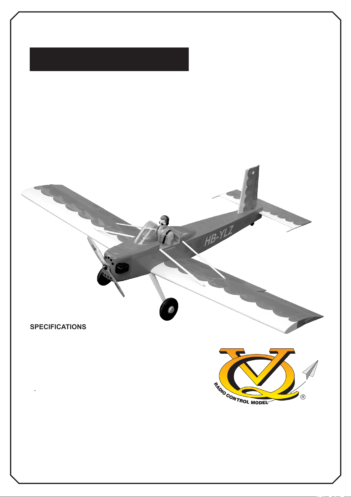
VOLKSPLANE
U.S VERSION: VQA133US SWISS VERSION: VQA134BLUE
SWISS VERSION: VQA134RED
SPECIFICATIONS
Wingspan 62.9in.
Length 46 in.
Electric Motor (See next page)
Radio 5 Channel / 4 Servos
TECHNISCHE DATEN
Spannweite 1600mm
Lange 1170mm
Elektroantrieb (siehe nächste Seite)
Fernsteuerung 5 Kanal / 4 Servos
WARNING! This radio controlled model is NOT a toy. If modified or flown carelessly it could go out of controll and
cause serious human injury or property damage. Before flying your airplane, ensure the air field is spacious enough.
Always fly it outdoors in safe areas and seek professional advice if you are unexperienced.
ACHTUNG! Dieses ferngesteuerte Modell ist KEIN Spielzeug! Es ist für fortgeschrittene Modellflugpiloten bestimmt,
die ausreichende Erfahrung im Umgang mit derartigen Modellen besitzen Bei unsachgemäßer Verwendung kann
hoher Personen- und/oder Sachschaden entstehen. Fragen Sie in einem Modellbauverein in Ihrer Nähe um
professionelle Unterstützung, wenn Sie Hilfe im Bau und Betrieb benötigen. Der Zusammenbau dieses Modells ist
durch die vielen Abbildungen selbsterklärend und ist für fortgeschrittene, erfahrene Modellbauer bestimmt.
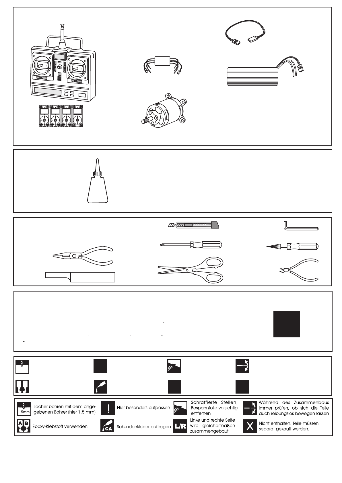
REQUIRED FOR OPERATION (Purchase separately)
Motor Control
Extension for aileron
servo.
Li-Po Battery, 3700mAh.
Minimum 5 channel radio
650-800W Brushless Motor
for airplane with 4 servos
Cyanoacrylate Glue
Sekundenkleber
CA
Tool Required/ Empfohlenes Werkzeug
.........................................................
.........................................................
.........................................................
.........................................................
.........................................................
.........................................................
.........................................................
.........................................................
.........................................................
.........................................................
.........................................................
The pre-covered film on ARF kit may wrinkle due to variations of temperature.
Store model in a cool and dry place for awile.
Then, staring with low heat, you may carefully use a hair dryer to smooth out wrinkels.
Die Bespannung des Modells kann durch Temeratureinflusse erschlaffen oder Falten
werfen z.b bei zu starker Sonnenenstrahlung oder Hitze.
Stellen Sie das Modell zunachst an einen kuhlen Platz fur eine bestimmte Zeit. Danach
konnen Sie versuchen die restlichen Falten vorstichtig mit einem Haartrockner zu behandeln.
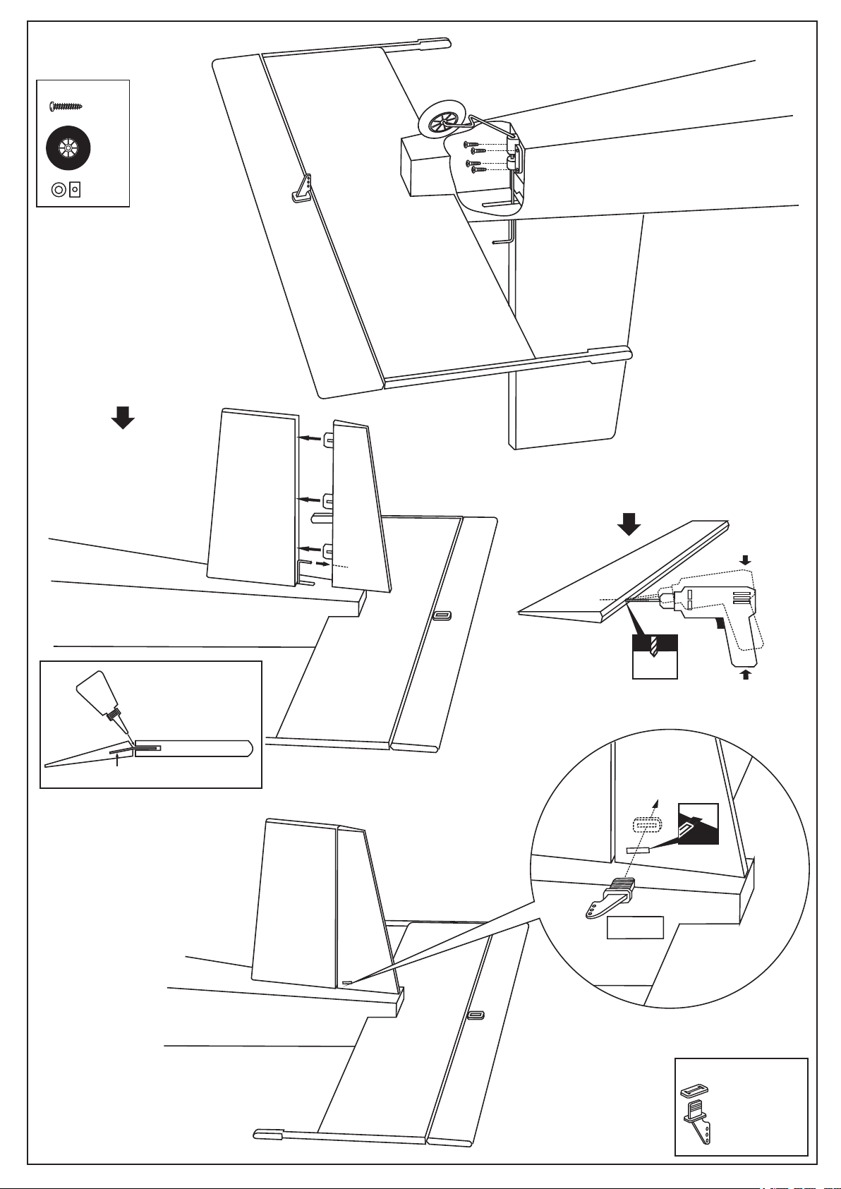
Drill holes using the stated
1.5mm
size of drill
(in this case 1.5 mm Ø)
A
B
Use epoxy glue
Take particular care here
!
Apply cyano glue
CA
Hatched-in areas:
remove covering
film carefully
Assemble left and right
L/R
sides the same way.
X
CONVERSION TABLE
1.0mm = 3/64”
1.5mm = 1/16”
2.0mm = 5/64”
2.5mm = 3/32”
3.0mm = 1/8”
4.0mm = 5/32”
5.0mm = 13/64”
6.0mm = 15/64”
10mm = 13/32”
12mm = 15/32”
15mm = 19/32”
20mm = 51/64”
25mm = 1”
30mm = 1-3/16”
45mm = 1-51/64”
!
Check during assembly that these
parts move freely, without binding
Not included.
These parts must be
purchased separately
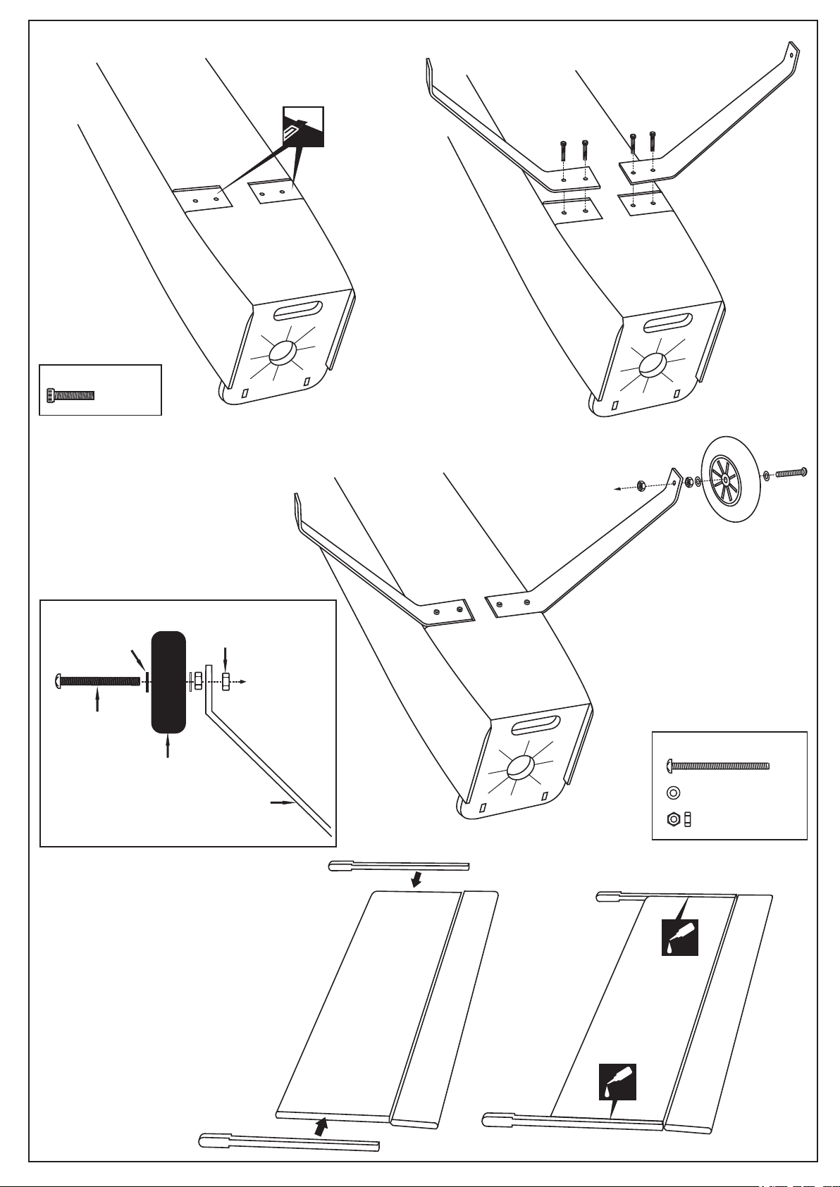
1
FUSELAGE - BOTTOM VIEW
Cut away only
the covering
1A
3x15mm screw
* WARNING: When removing any covering from the airframe, please ensure that you secure the
cut edge with CA or similar cement. This will ensure the covering remain tight.
4mm washer
...4
4mm bolt
1B
1C
4x45mm screw
75mm wheel
Aluminum landing gear
4X45mm
...2
4mm ...................4
4mm.................4
CA
CA
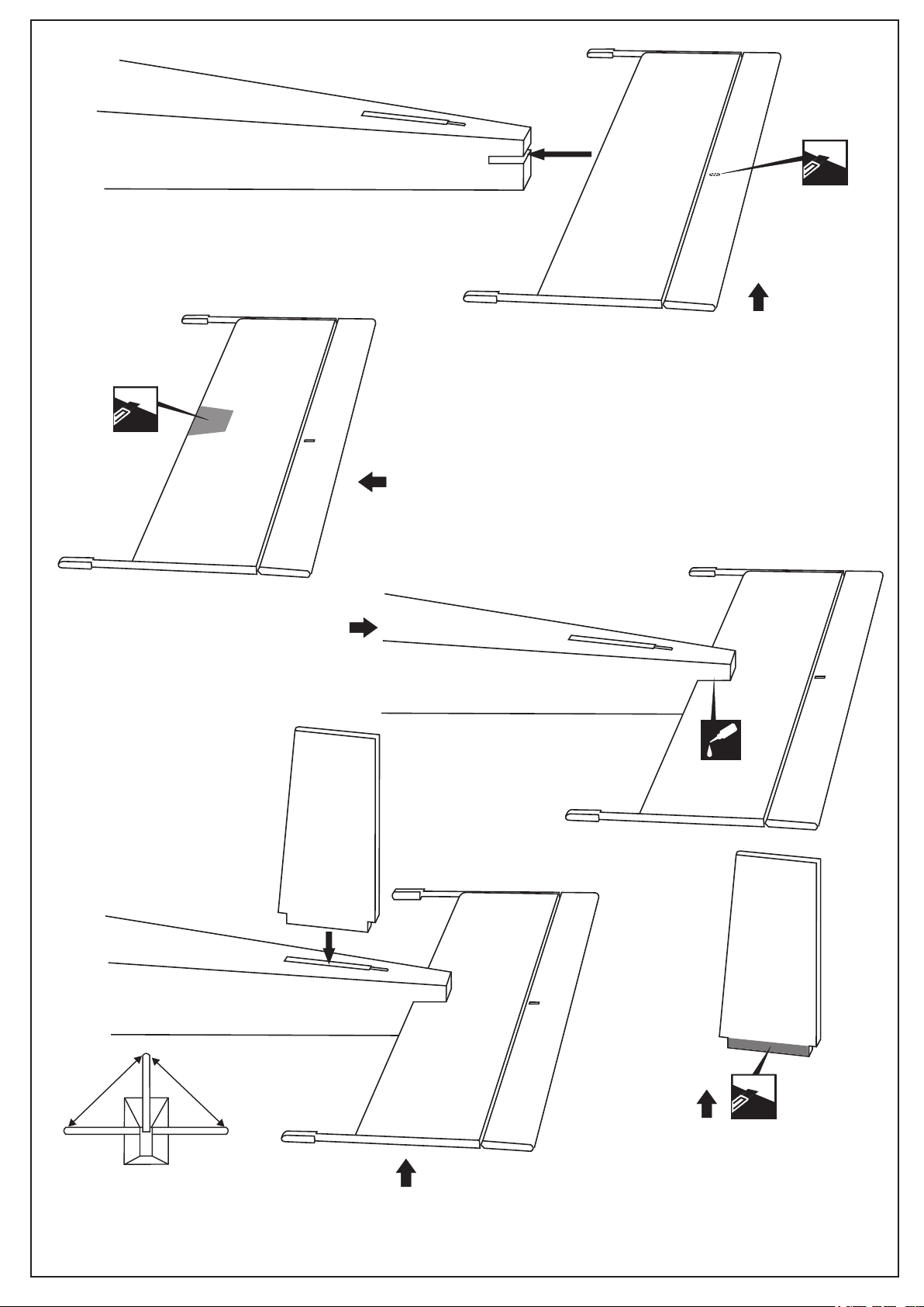
2
NOTE: cut inside the pencil lines.
Cut away only
the covering
both sides.
2B
Trial fit the horizontal stabilizer in place on the
fuselage. Check the alignment of the horizontal
stabilizer by measuring from a fixed point along
the center line of the fuselage to the leading edge
on each side of the horizontal stabilizer. The
distance must be equal on both sides.
Using the pencil trace around the top and bottom
of the stabilizer where it meets the fuselage.
NOTE: Do not glue the horizontal stabilizer into
Remove the horizontal stabilizer from the fuse lage. Remove the covering material from the gluing
surfaces on both the top and bottom of the horizontal
stabilizer.
the fuselage at this time.
Cut away only
the covering
2A
Again, slide the horizontal stabilizer into the
fuselage. Check the alignment of the horizontal
stabilizer. Secure the horizontal stabilizer in place
using the thin CA glue.
Securely glue together. If coming off during
flight, you lose control of your air plane.
2D
2C
CA
2E
B
Trial fit the horizontal stabilizer in place on the fuselage.
Check the alignment with the horizontal stabilizer The distance must
be equal on both sides (B=B’).
Using the pencil trace around the top and bottom of the stabilizer where it
meets the fuselage.
B’
Cut away only
Remove the vertical stabilizer from the fuselage.
Remove the covering material from the gluing
surfaces on both the left and right of the vertical
stabilizer.
* WARNING: When removing any covering from
the airframe, please ensure that you secure the
cut edge with CA or similar cement. This will
ensure the covering remain tight.
the covering
both sides

3
Again, push the vertical stabilizer into the
fuselage. Check the alignment with the horizontal
stabilizer. Secure the vertical stabilizer in place
using the thin CA glue.
3A
CA
Securely glue together. If coming off during
flight, you lose control of your air plane.
Thin CA
CA
3D
After snapping, secure the
control horn flat with thin
CA glue.
3B
Cut away only
the covering
3C
Plastic control horn
.....................1
4
3x10mm
Without using glue yet, push the rudder
and its hinges into the hinge slots in the
trailing edge of the vertical stabilizer.
When satisfied with the alignment, mark
the mounting hole position, where the
rudder torque rod meets the rudder with
a pencil.
....4
....1
....2
4B
4A
Remove the rudder and drill a 2mm diameter hole in
torque rod mounting slot, making sure that you drill
the hole perpendicular to the leading edge of the
rudder.
CA
Apply thin CA to both
side of the hinge
Hinge
STABILIZER
4D
4C
5/64”
2mm
Cut away only
the covering
WRONG
RIGHT
Plastic control horn
.....................1
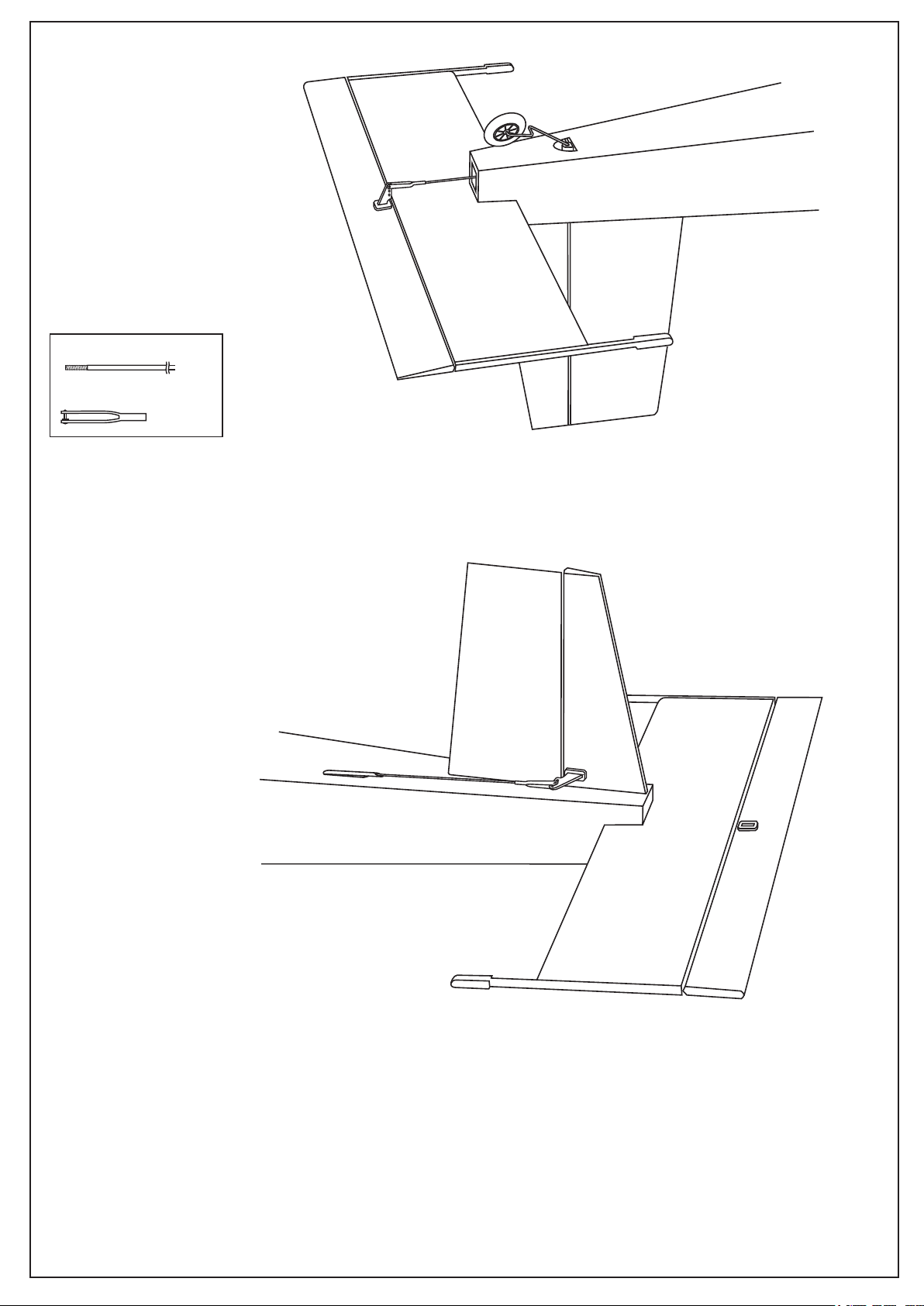
5
950mm steel wire
Steel clevis
5A
......2
......2
FUSELAGE - BOTTOM VIEW
5B
FUSELAGE - TOP VIEW

6
Using a aluminum motor mounting as a template,
mark the fire-wall where the four holes are to be
drilled .
6A
4mm
Remove the motor and drill a 4mm hole
through the fire-wall at each of the four marks
marked .
6B
6C
3x15mm
...4
...4

7
7A
7B
7C
Adhesive tape
1mm
1mm
1mm
2x8mm
7D
2x8mm
......6
2x8mm
7E
1mm
2x8mm
......4

8
2mm connector
...2
CA
Rudder servo
Elevator servo
Fuselage - Top view
8B
8A
Note: The holes for the connector installation
are pre-drilled at factory
3mm connector
...4
CA
8C
Cut away only
the covering

9
CA
CA
L/R
Do the same way with other wing half
BOTTOM - VIEW
9A
Control horn
..........2
2x30mm
...4
2mm
2mm connector
175mm steel wire
Steel clevis
X
........2
......2
......2
Aileron
extension cord
9B
Aileron pushrod
X
L/R
Do the same way with other wing half
BOTTOM - VIEW

10
10A
10B
10C
Note: The hole on the surface of the top of the
wing is pre-drilledat factory.
3x15mm screw
.........2
Secure the wing in place
using 3x15mm screw.
TOP
Aluminum
tube inside
2.mm drill bit
A
2mm
3x15mm screw
B

11
3x12mm
3x12mm
.........4
3x12mm
Note: The holes on the top of the
12
wing are pre-drilled at factory.
Note: The length of the wing brace can adjust by turn the
metal hook.
The recommended C.G (Center of Gravity) location for the Volksplane is 89 ~ 91mm
Adjust the location of the battery pack as required to achieve this C.G location.
If necessary , add weight to either the tail or nose until the correct balance is achieve.
78 ~ 83mm
Wing brace
CG
WARNING ! Securely install the receiver and power pack, ensuring they will not come loose or rattle during flight.
Never fly before checking the Cg’s required position.
Control Surface
25/64”(10mm)
25/64”(10mm)
AILERON STROKE
25/64”(10mm)
25/64”(10mm)
ELEVATOR STROKE
1”(25mm)
1”(25mm)
RUDDER STROKE
 Loading...