

VQ Models SCOOTER Instruction Manual
SPECIFICATIONS
Wingspan:........................1630mm (64.1in.)
Length:................................1170mm (46in.)
Electric Motor:.....................See next pager
RTF Weight: 2.6Kg / 5.7lbs (Will vary with
Equipment Used).
Radio:....................6 Channel / 6 Servos
Function: Ailerons-Flaps-Elevator-Rudder-Motor
WARNING! This radio controlled model is NOT a toy. If modified or flown carelessly it could go out of controll and
cause serious human injury or property damage. Before flying your airplane, ensure the air field is spacious enough.
Always fly it outdoors in safe areas and seek professional advice if you are unexperienced.
ACHTUNG! Dieses ferngesteuerte Modell ist KEIN Spielzeug! Es ist für fortgeschrittene Modellflugpiloten bestimmt,
die ausreichende Erfahrung im Umgang mit derartigen Modellen besitzen. Bei unsachgemässer Verwendung kann
hoher Personen- und/oder Sachschaden entstehen. Fragen Sie in einem Modellbauverein in Ihrer Nähe um
professionelle Unterstätzung, wenn Sie Hilfe im Bau und Betrieb benötigen. Der Zusammenbau dieses Modells ist
durch die vielen Abbildungen selbsterklärend und ist für fortgeschrittene, erfahrene Modellbauer bestimmt.
Radio control model / Flugmodel
ALL BALSA, PLYWOOD CONSTRUCTION AND ALMOST READY TO FLY
Instruction manual / Montageanleitung
TECHNISCHE DATEN
Spannweite:...................................1630mm
Lange:............................................1170mm
Elektroantrieb.............(siehe nächste Seite)
Brushless Motor:.............
Fluggewicht:.......................................2.6Kg
Fernsteuerung................6 Kanal / 6 Servos

1.5mm
A
B
!
CA
L/R
Assemble left and right
sides the same way.
X
Drill holes using the stated
size of drill
(in this case 1.5 mm )
Use epoxy glue
Take particular care here
Hatched-in areas:
remove covering
film carefully
Not included.
These parts must be
purchased separately
Check during assembly that these
parts move freely, without binding
Apply cyano glue
SILICON
CA
GLUE
X1075 Silex Silicon
# X3572 Zoom Sekundenkleber
TOLLS REQUIRED
Hobby knife
Needle nose Pliers
Phillip screw driver
Awl
Scissors
Wire Cutters
(Purchase separately)
Hex Wrench
.........................................................
.........................................................
.........................................................
.........................................................
.........................................................
.........................................................
.........................................................
.........................................................
.........................................................
.........................................................
.........................................................
Sander
Masking tape - Straight Edged Ruler - Pen or pencil - Drill and Assorted Drill Bits
Read through the manual before you begin, so you will have an overall idea of what to do.
Symbols used throughout this instruction manual, comprise:
(Purchase separately)
CONVERSION TABLE
1.0mm = 3/64”
1.5mm = 1/16”
2.0mm = 5/64”
2.5mm = 3/32”
3.0mm = 1/8”
4.0mm = 5/32”
5.0mm = 13/64”
6.0mm = 15/64”
10mm = 13/32”
12mm = 15/32”
15mm = 19/32”
20mm = 51/64”
25mm = 1”
30mm = 1-3/16”
45mm = 1-51/64”
If exposed to direct sunlight and/or heat, wrinkels can appear. Storing the
model in a cool place will let the wrinkles disappear. Otherwise, remove
wrinkles in covering film with a hair dryer, starting with
low temperature. You can fix the corners by using a hot iron.
Bei Sonneneinstrahlung und/oder Wärme kann die Folie erschlaffen bzw. Falten
entstehen. Verwenden Sie ein Warumluftgebläse (Haartrockner) um evtl. Falten aus der Folie
zu bekommen. Die Kanten können Sie mit einem Bügeleisen behandeln. Nicht zuviel Hitze anwenden !
REQUIRED FOR OPERATION (Purchase separately)
Low seting
# C2983
Brushless Combo BOOST 40
inkl. Motor, Regler, Programmkarte
including motor, ESC and program card
# C6741 LiPo LEMONRC 3700-11,1V
EPOXY A
EPOXY B
# C5753
Propeller P-CON 12x6
# C4995
MASTER Digital Servo DS3012 oder/or
# C5638
MASTER Digital Servo DS3012 MG
# C2036
Servo Verlängerungskabel 400mm
Servo Extension Cord 400mm
CA Glue
X3598-120 Epoxy
5-Min.
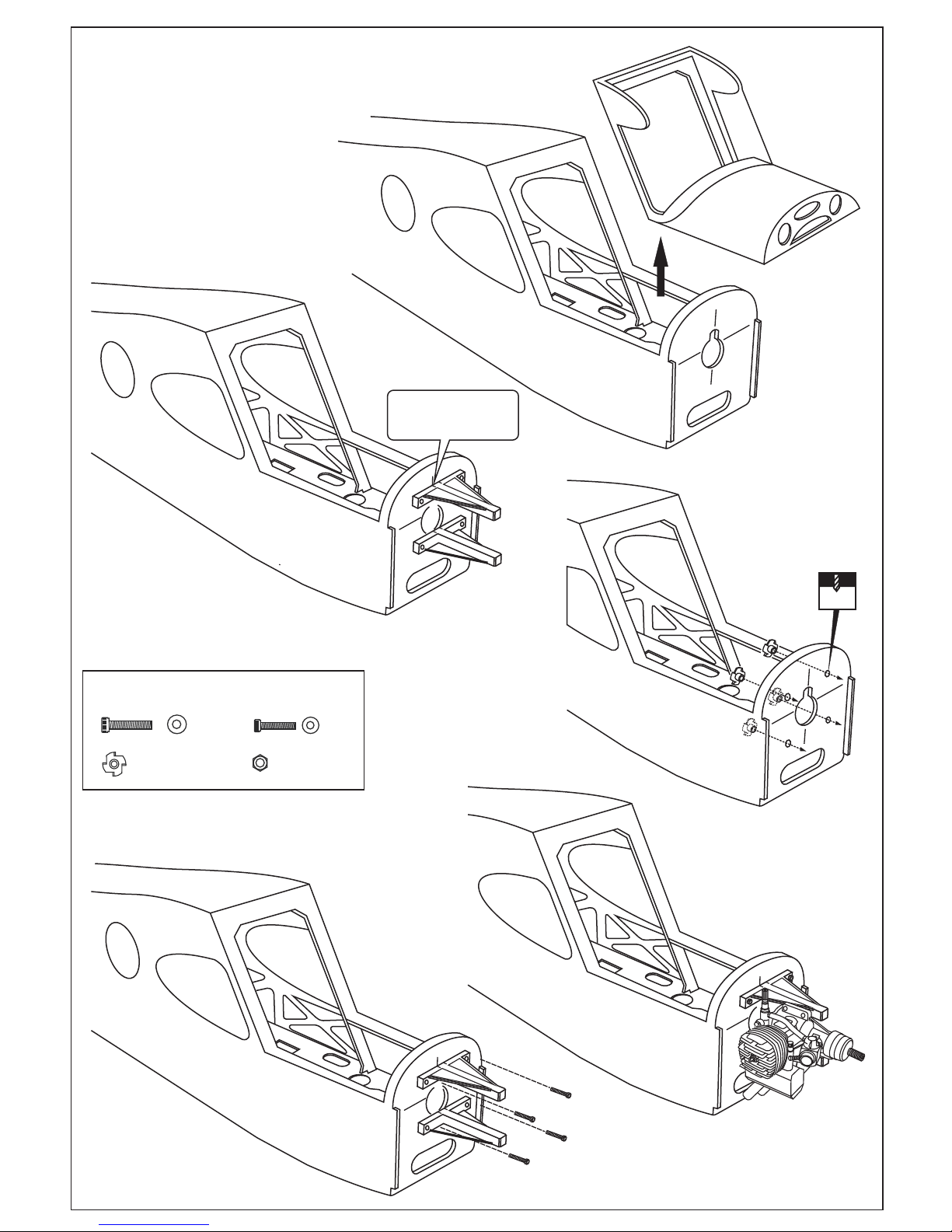
1
Pull the magnetic top hatch out
of the fuselage.
Using a pencil or felt tipped pen,
mark the fire wall where the four
holes are to be drilled.
! Align the mark on both
mounts with the mark
on the fuselage
Position the engine on to the engine mounts
so the distance from the prop hub to the firewall is 112mm.
...4
.................4
4x25mm screw
Blind-nut
3x20mm screw
1/8”(3mm) nut
.................4
...4
4x20mm screw
1A
1B
1C
Remove the engine mounts
and drill four 5mm holes
as marked.
5mm
1D
1E
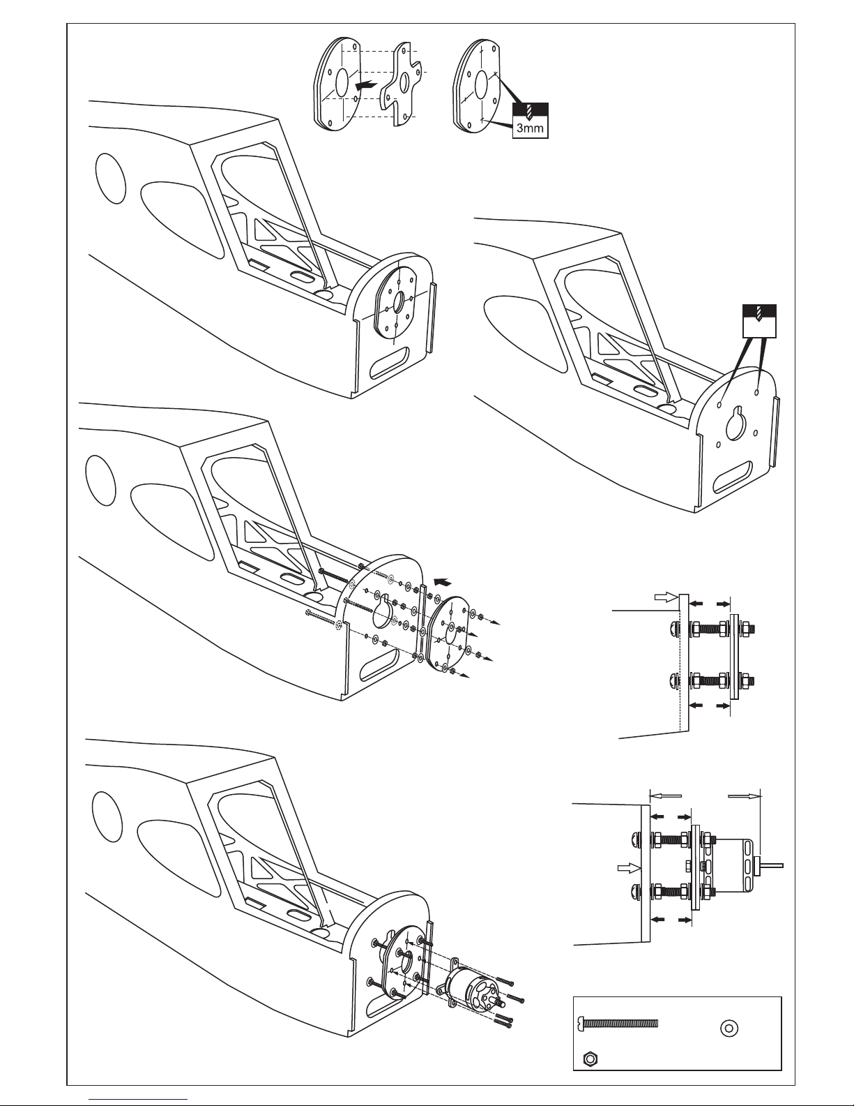
A=A’
! Engine thrust on balk head
is already adjust at factory
Attach the aluminum motor
mounting plate on to the motor
and secure it in place with four
screws ( included with motor set).
Reposition the plywood motor mounting plate and secure
it in place with twelve 5xmm nuts and washers (6).
Note: B=B’(top-view) and A=A’(side-view)
Using a plywood motor mounting plate as a template,
mark the fire wall where the four holes are to be drilled .
X4
X16
X12
5x60mm screw
5mm washer
5mm nut
Remove the plywood motor mounting plate and drill a
13/64”(5mm) hole through the fire-wall at each of the four
marks marked above.
Using the aluminum mounting plate as
template, mark the plywood motor mounting
plate where the four holes are to be drilled
(2A).
Remove the aluminum mounting plate and
drill 3mm hole through the plywood at each
of the four marks marked (2B).
Note: The aluminum motor mounting
included with electric motor set.
112mm
A
A’
Fire-wall
Fire-wall
2
2A
2B
2C
5mm
B’
B
SIDE VIEW
TOP VIEW
2D
2E
 Loading...