

VQ Models monaro sport 60 Instruction Manual
SPORT
60
60 Class - 2 Cycle engine
90 Class - 4 Cycle engine
Radio control model - RC Flugmodell
SPECIFICATIONS
Wingspan 67.3 in.
Length 51.1 in.
Electric Motor 1000 Watt (BOOST 90)
Glow Engine 60 2-T / 90cc 4-T
Radio 5 Channel / 5 Servos
TECHNISCHE DATEN
Spannweiter 1710mm
Lange 1030mm
Elektroantrieb 1000 Watt (BOOST 90)
Verbrennerantrieb 60 2-T / 90 4-T
Fernsteuerung 5 Kanal / 5 Servos
WARNING! This radio controlled model is NOT a toy. If modified or flown carelessly it could go out of controll and
cause serious human injury or property damage. Before flying your airplane, ensure the air field is spacious enough.
Always fly it outdoors in safe areas and seek professional advice if you are unexperienced.
ACHTUNG! Dieses ferngesteuerte Modell ist KEIN Spielzeug! Es ist für fortgeschrittene Modellflugpiloten bestimmt,
die ausreichende Erfahrung im Umgang mit derartigen Modellen besitzen Bei unsachgemäßer Verwendung kann
hoher Personen- und/oder Sachschaden entstehen. Fragen Sie in einem Modellbauverein in Ihrer Nähe um
professionelle Unterstützung, wenn Sie Hilfe im Bau und Betrieb benötigen. Der Zusammenbau dieses Modells ist
durch die vielen Abbildungen selbsterklärend und ist für fortgeschrittene, erfahrene Modellbauer bestimmt.
INSTRUCTION MANUAL / Montageanleitung
Or electric equivalent
1.5mm
A
B
!
CA
L/R
Assemble left and right
sides the same way.
X
Drill holes using the stated
size of drill
(in this case 1.5 mm Ø)
Use epoxy glue
Take particular care here
Hatched-in areas:
remove covering
film carefully
Not included.
These parts must be
purchased separately
Check during assembly that these
parts move freely, without binding
Apply cyano glue
The pre-covered film on ARF kit may wrinkle due to variations
of temperature. Smooth out as explained right.
* Use an iron or heat gun. Start as low setting. Increase the
setting if necsessary. If it is too high, you may damage the
film
Low setting
SILICON
EPOXY A
EPOXY B
CA
GLUE
Epoxy Glue ( 5 minute type)
Silicon sealer
Cyanoacrylate
Glue
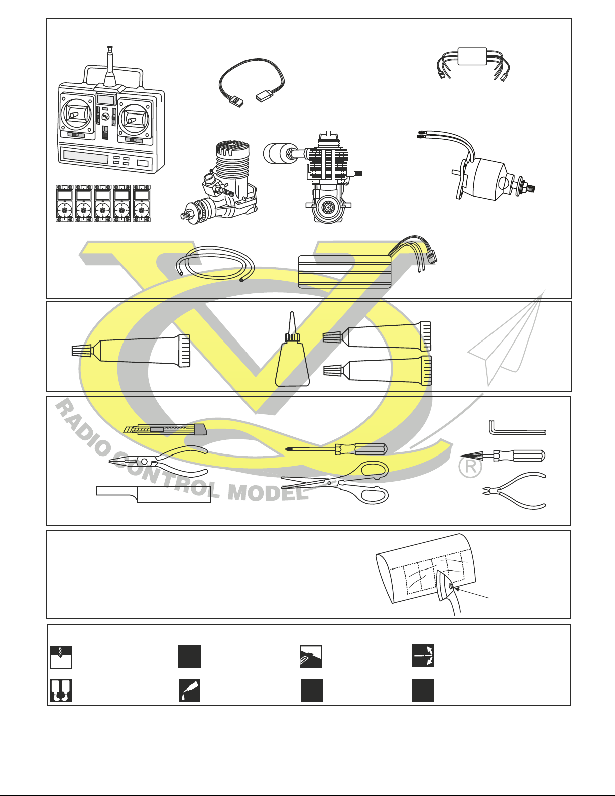
Minimum 5 channel radio
for airplane with 5 servos
.90 - 4 cycle
Silicone tube
Extension for aileron
servo.
.60 - 2 cycle
REQUIRED FOR OPERATION (Purchase separately)
Epoxy Glue (30 minute type)
TOLLS REQUIRED
Hobby knife
Needle nose Pliers
Phillip screw driver
Awl
Scissors
Wire Cutters
(Purchase separately)
Hex Wrench
.........................................................
.........................................................
.........................................................
.........................................................
.........................................................
.........................................................
.........................................................
.........................................................
.........................................................
.........................................................
.........................................................
Sander
Masking tape - Straight Edged Ruler - Pen or pencil - Rubbing alcohol - Drill and Assorted Drill Bits
Read through the manual before you begin, so you will have an overall idea of what to do.
Symbols used throughout this instruction manual, comprise:
(Purchase separately)
.Motor control x1 .Aileron x2
.Elevator x1 .Rudder x1
1000w
Brushless Motor
70A Regler
Li-Po Battery, 22.2V, 5300mAH
CONVERSION TABLE
1.0mm = 3/64”
1.5mm = 1/16”
2.0mm = 5/64”
2.5mm = 3/32”
3.0mm = 1/8”
4.0mm = 5/32”
5.0mm = 13/64”
6.0mm = 15/64”
10mm = 13/32”
12mm = 15/32”
15mm = 19/32”
20mm = 51/64”
25mm = 1”
30mm = 1-3/16”
45mm = 1-51/64”
* WARNING: When removing any covering from
the airframe, please ensure that you secure the
cut edge with CA or similar cement. This will
ensure the covering remain tight.
Cut away only the
covering
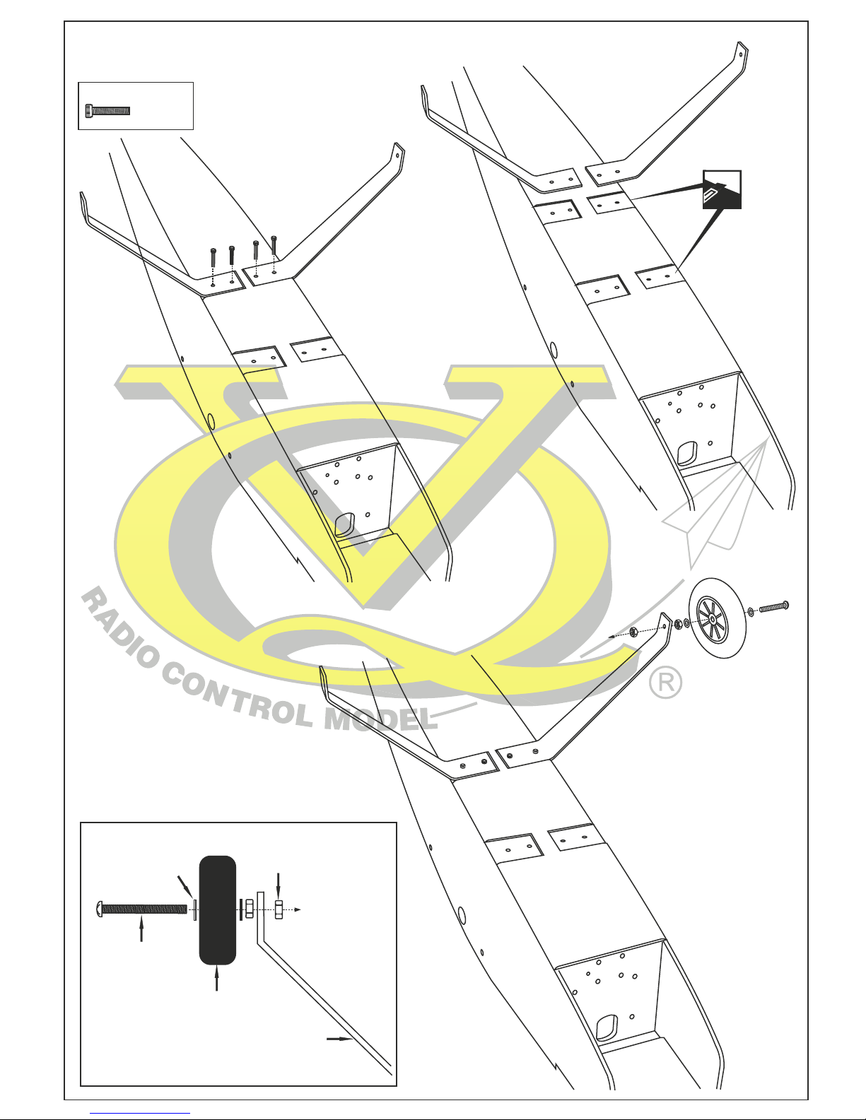
IN CASE OF NOSE GEAR USING
3x15mm screw
4x45mm screw
4mm bolt
4mm washer
75mm wheel
Aluminum landing gear
1- Landing gear
...4
3x15mm screw
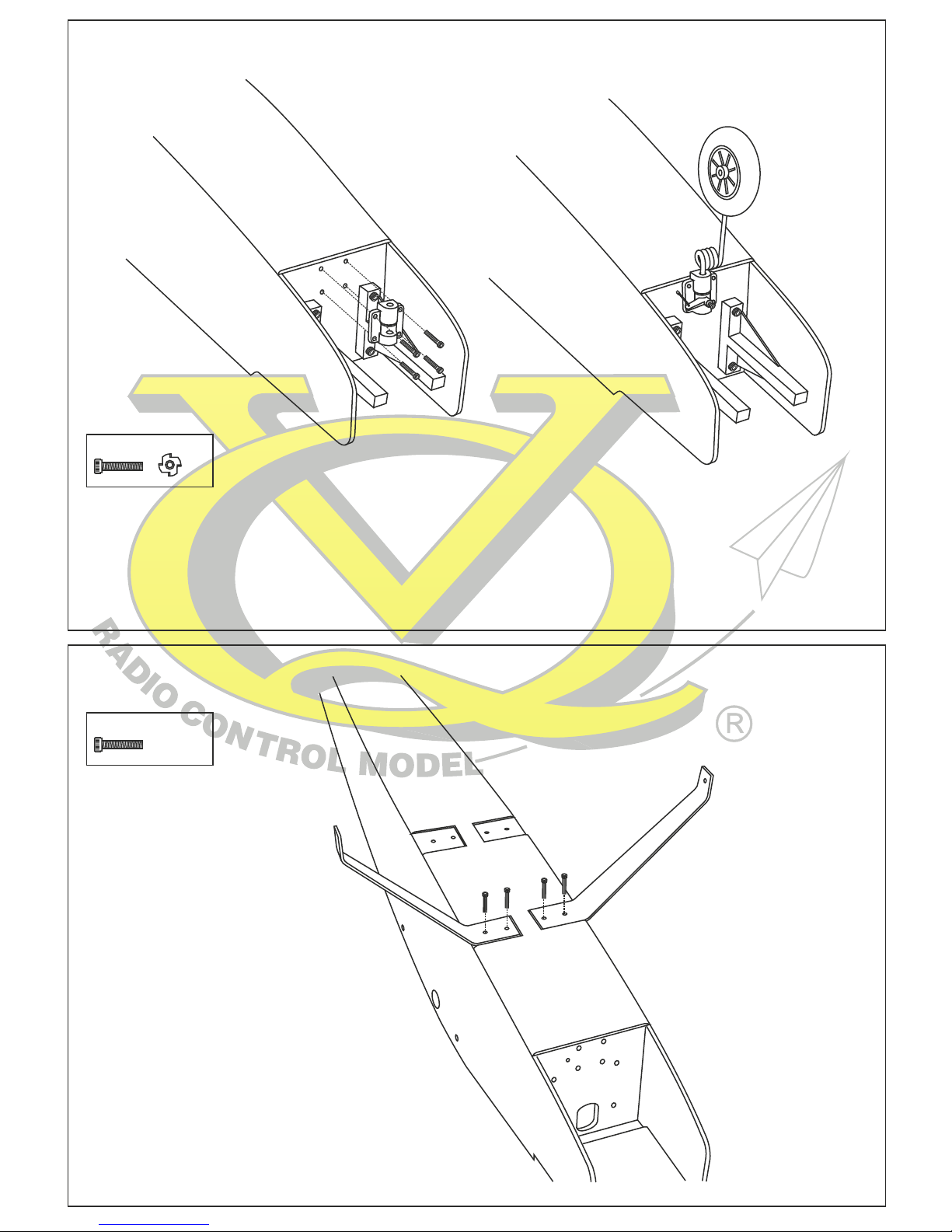
IN CASE OF TAIL GEAR USING
1-Securely attach the nose gear mount to the fire-wall using the four 3x15mm screws
2-Insert the white plastic tube into the fuselage, through the firewall.
3-Insert the Z-bend of the nose gear control push-rod into the hole on the nose gear control horn.
4-Insert the pus-hrod into the plastic tube
5-Position the nose gear control horn on the center of the nose gear mount.
6-With the screw hole facing forward, slide the straight end of the nose gear on to the nose gear mount.
7-When satisfied with the fit and alignment, secure the nose gear control horn in place with 1/8x13/32”(3x10mm) set screw.
...4
3x15mm screw
2- Nose gear
3- Landing gear
65mm wheel
...4
3x15mm screw
* WARNING: When removing any covering from
the airframe, please ensure that you secure the
cut edge with CA or similar cement. This will
ensure the covering remain tight.
 Loading...