


Semi scale model
40 Class
52 Class
2-cycle engine
4-cycle engine
RADIO CONTROLED ALMOST READY-TO-FLY ENGINE POWERED ALL BALSA PLANE
VQA09 / VQA091
Or Electric equivalent
BUILDING INSTRUCTIONS / MONTAGEANLEITUNG
SPECIFICATIONS
Wingspan
Length
Flying weight
Electric Motor
Glow Engine
Radio
Technische Daten
Spannweite
Länge
Fluggewicht
Elektroantrieb
Verbrennerantrieb
Fernsteuerung
1580mm
1160mm
2500g
650 Watt (BOOST 40)
6,5cc 2T / 8,5cc 4-T
4 Channel / 4 Servos
1580mm
1160mm
2500g
650 Watt (BOOST 40)
6,5cc 2T / 8,5cc 4T
4 Kanal / 4 Servos
WARNING! This radio controlled model is NOT a toy. If modified or flown carelessly it could go out of controll and
cause serious human injury or property damage. Before flying your airplane, ensure the air field is spacious enough.
Always fly it outdoors in safe areas and seek professional advice if you are unexperienced.
ACHTUNG! Dieses ferngesteuerte Modell ist KEIN Spielzeug! Es ist für fortgeschrittene Modellflugpiloten bestimmt,
die ausreichende Erfahrung im Umgang mit derartigen Modellen besitzen Bei unsachgemäßer Verwendung kann
hoher Personen- und/oder Sachschaden entstehen. Fragen Sie in einem Modellbauverein in Ihrer Nähe um
professionelle Unterstützung, wenn Sie Hilfe im Bau und Betrieb benötigen. Der Zusammenbau dieses Modells ist
durch die vielen Abbildungen selbsterklärend und ist für fortgeschrittene, erfahrene Modellbauer bestimmt.
1.5mm
A
B
!
CA
L/R
Assemble left and right
sides the same way.
X
Drill holes using the stated
size of drill
(in this case 1.5 mm Ø)
Use epoxy glue
Take particular care here
Hatched-in areas:
remove covering
film carefully
Not included.
These parts must be
purchased separately
Check during assembly that these
parts move freely, without binding
Apply cyano glue
Low setting
SILICON
EPOXY A
EPOXY B
CA
GLUE
Epoxy Glue (5 minute type)
Silicon sealer
Cyanoacrylate
Glue
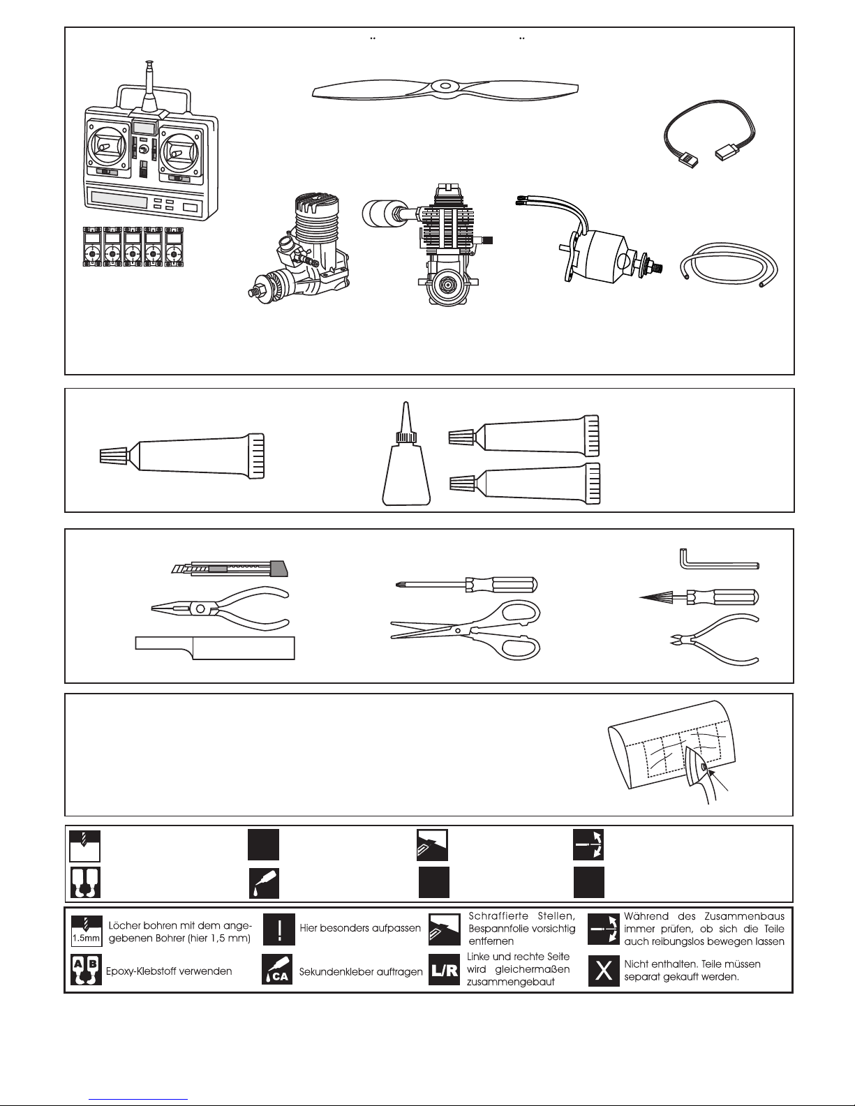
.52-.60 - 4 cycle
10.5x6 for .40 - 2 cycle engine
11x6 for .46 - 2 cycle engine
11X7 for .52 - 4 cycle engine
Silicone tube
Extension for aileron servo
.40-.45 - 2 cycle
OPTIONAL ACCESSORIES / BENOTIGTES ZUBEHOR
Epoxy Glue (30 minute type)
TOLLS REQUIRED
Hobby knife
Needle nose Pliers
Phillip screw driver
Awl
Scissors
Wire Cutters
(Purchase separately)
Hex Wrench
.........................................................
.........................................................
.........................................................
.........................................................
.........................................................
.........................................................
.........................................................
.........................................................
.........................................................
.........................................................
.........................................................
Sander
Masking tape - Straight Edged Ruler - Pen or pencil - Rubbing alcohol - Drill and Assorted Drill Bits
Read through the manual before you begin, so you will have an overall idea of what to do.
(Purchase separately)
CONVERSION TABLE
1.0mm = 3/64”
1.5mm = 1/16”
2.0mm = 5/64”
2.5mm = 3/32”
3.0mm = 1/8”
4.0mm = 5/32”
5.0mm = 13/64”
6.0mm = 15/64”
10mm = 13/32”
12mm = 15/32”
15mm = 19/32”
20mm = 51/64”
25mm = 1”
30mm = 1-3/16”
45mm = 1-51/64”
If exposed to direct sunlight and/or heat, wrinkels can appear. Storing the
model in a cool place will let the wrinkles disappear. Otherwise, remove
wrinkles in covering film with a hair dryer, starting with
low temperature. You can fix the corners by using a hot iron.
Bei Sonneneinstrahlung und/oder Wärme kann die Folie erschlaffen bzw. Falten
entstehen. Verwenden Sie ein Warumluftgebläse (Haartrockner) um evtl. Falten aus der Folie
zu bekommen. Die Kanten können Sie mit einem Bügeleisen behandeln. Nicht zuviel Hitze anwenden !
Klebstoff
Epoxy-Klebstoff (30min-Typ)
Epoxy-Klebstoff (5min-Typ)
Minimum 5 channel radio
for airplane with 5 servos
.Motor control x1
.Aileron x 2
.Elevator x1
.Rudder x1
650 Watt
Brushless motor

A
B
A
B
! Make sure to glue
securely, If not properly
glued, a failure in flight may
occur.
Trial fit each part before gluing . Be certain that there
are no gaps. If the parts will join,
but with a gaps, sand or trim the parts a little at a time until
the parts meet exactly with no gaps.
Check for the correct dihedral angle
Carefully slide the wing halves together, ensuring that they are
accurately aligned, Firmly press the two halves together,
allowing the excess epoxy run out.
When joining the wing halves it is extremely important to use
plenty of epoxy (30 minutes epoxy).
Use epoxy glue to bury the opening
WING TOP-VIEW
1-
Joining the wing / Flachenverbindung
IMPORTANT:
Please do not clean off the excess epoxy on the wing
with strong solvent or pure alcohol, only use kerosene
to keep the colour of your model not fade.
Secure one end of the
thread with adhesive tape
Secure one end of the
thread with adhesive tape
Binder clip
Nylon wing bolt
Rubber band
(both the top
and bottom)
2- Aileron Servo extension cord
BOTTOM VIEW
Carefully, to link the end of the thread
to the aileron servo extension cord before
to install the aileron servo to the wing.
Thread
Thread
*Servo Extension Standard 500mm
CJ0500STD
X
X
3- Aileron Servo / Querruder servo
BOTTOM VIEW
Adhesive
tape
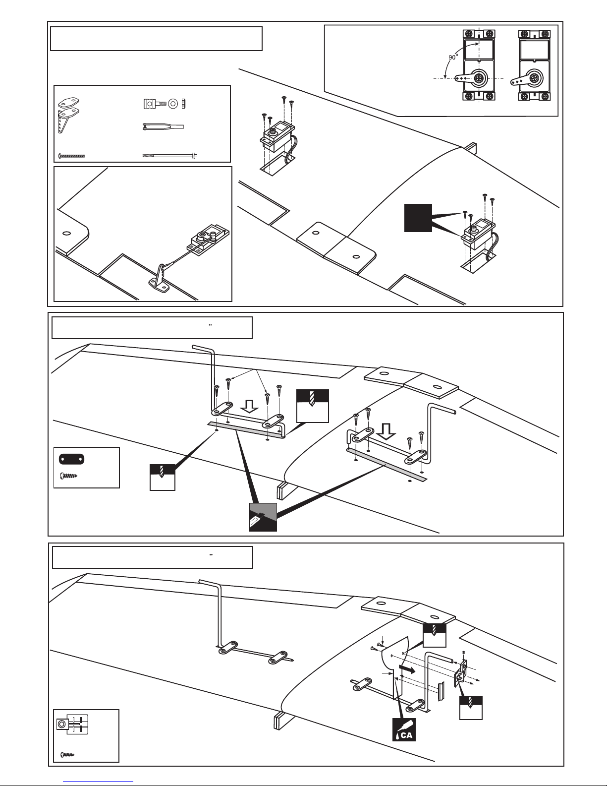
4- Aileron Servo / Querruder servo
Plastic control horn
....................2
2x20mm screw
..............4
Connector
............2
Aileron linkage
............2
......2
Aileron push rod
X
BOTTOM VIEW
-Switch on the radio (trims
centered) then mount the
ailerons servo horn in neutral
position.
-The servo horn should be
perpendicular to the servo
YES
NO
3X12mm screw
Cut away only the film
WING BOTTOM-VIEW
Position the two landing gear and plastic straps.
Secure the landing gear and plastic straps in place with 3x12mm
screws.
Drilled at factory
Drilled at factory
.....4
.....8
5- Fixed gear / Landegestange
WING BOTTOM-VIEW
ABS Gear cover
2x10mm
2mm
5/64”
6- Fixed gear / Landegestange
.....2
.....4
2mm
5/64”
2x10mm screw
6A
6B
6C

! Engine thrust on balk head
is already adjust at factory
! Align the mark on both mounts
with the mark on the fuselage
8- Engine mount / Motortrager
A
A
B
B’
B=B’
FRONT-VIEW
5mm
- Remove the engine mount and drill a 13/64”(5mm) hole through
the fire-wall at each of the four marks marked.
- Attach the four blind-nut to the fire-wall as show
- Using a pencil or felt tipped pen, mark the fire wall where the four
holes are to be drilled
- Reposition the engine mounts on to the fire-wall and secure them
with four 4x25mm screw
- Reposition the engine on to the engine mounts so the distance
from the prop hub to the fire wall is 4-3/4”(121mm)
4-3/4”(121mm)
! Engine thrust on balk
head is already adjust
at factory
1.5
TOP-VIEW
13/64”
- Mark the engine mounting plate where the four holes are to be
drilled.
Note: Mark the mounting plate through the engine mounting flanges.
- Remove the engine and drill a 1/8”(3mm) holes through the beam
at each of the four marks made above.
- Reposition the engine on the engine mount beams, aligning it with
the holes. Secure the engine to the engine mount using four
1/8x1”(3x25mm) screws.
3mm
1/8”
Note: Apply Silicon sealer to
each of the 1/8x1”(3x25mm) screw.
...4
.................4
4x25mm screw
Blind-nut
3x25mm screw
1/8”(3mm) nut
.................4
...4
1/8x1”
5/32x1”
5/32”(4mm)
stopper
WING BOTTOM-VIEW
.....2
7- Fixed gear / Landegestange
4mm collar

Slide the nose gear push rod through the nose gear control horn.
With the screw hole facing forward, slide the nose gear control horn onto
the straight end of the nose gear so the so the steering arm extends in the
opposite direction of the nose gear axle.
Rotate the nose wheel back and forth a few times to make sure it rotates
freely with out any binding.
Securely attach the nose gear mount to the
fire wall using the four 3x20mm(1/8X51/64”) screws.
A
B
9- Nose Gear / Bugfahrwerk
Slide the wheel onto the nose landing gear axles and secure it with the
supplied wheel collars.
.....................4
Blind-nut
............4
3x20mm screw
....................1
1/8x51/64”
NOSE WHEEL
NOSE WHEEL ARM
NOSE WHEEL
PUSHROD
FIRE-WALL
TOP-VIEW
X
To muffler
Filler tube
To engine
1/8x1-13/32”(3x35mm) screw
Rubber stopper
5/32”(4mm)
10- Fuel Tank Installation
Ensure that the fuel tank clunk does not touch the rear of the fuel tank.
Checking for leaks - block the vents and blow into the
feed - if in doubt submersing the tank in a blow of
water will show up any problems.
Blow
Water
2
After confirming the direction . Insert this assembly, clunk end
first, into the fuel tank and tighten and screw the fuel tank cap on
firmly.
Carefully install the fuel tank
to ensure that they will not
shift during flight (secure the
fuel tank in place using foam
padding).
1
3
To rudder servo

11- Electric Motor
FRONT-VIEW
- Using a plywood motor mounting plate as a template, mark the fire wall where the
four holes are to be drilled (1).
5mm
13/64”
! Align the mark on the plywood motor
mount with the mark on the fuselage.
! Align the mark on the plywood motor mount
with the center lines on aluminum motor mount.
- Remove the plywood motor mounting plate and drill a 13/64”(5mm) hole through the fire-wall at each of the four marks
marked (2).
- Using a aluminum motor mounting plate as a template, mark the plywood motor mounting plate where the four holes are
to be drilled (3).
- Remove the aluminum motor mounting plate and drill a 1/8”(3mm) hole through the plywood at each of the four marks
marked (4).
3mm
1/8”
1
2
3
4
Plywood motor
mounting plate (2pcs)
Aluminum motor
mounting plate
Firewall
121mm
(4-3/4”)
B’
B
B=B’
A
A=A’
A’
TOP-VIEW
SIDE-VIEW
! Engine thrust on balk head
is already adjust at factory
-Attach the aluminum motor mounting plate on to the motor and secure it in place with four screws ( included with motor set) (7).
-Push the four 5x70mm bolts through the fire-wall as shown (5).
- Reposition the plywood motor mounting plate (2pcs) and secure it in place with eight 5mm nuts and washers (6).
Note: B=B’(Side-view) and A=A’(Top-view)
-Attach the motor on to the plywood motor mounting plate and secure it in place with four 3x15mm (1/8x19/32”)
screws(8).
7 - 8
5
6
5x70mm.......4
5mm nut.......12
5mm washer...16
3mm screw/nut...4
12- Electric Motor
SILICON
Using silicon sealer, secure
the motor mount screw.

Cut away only
the film both side
A
B
Carefully slide the stabilizers onto the fuselage, ensuring that they are accurately aligned, Allowing
the excess epoxy run out. Clean off the excess epoxy.
When you are satisfied with the alignment, use a pencil to carefully trace around the left and
right of the Vertical stabilizer where them meet the fuselage. Note, it is important not to disturb
the alignment of the stabilizer.
Remove the vertical stabilizer from the fuselage. Using a sharp hobby knife, cut away the
covering inside the lines. Not to cut into the wood.
Spread epoxy onto the left and right of the vertical stabilizer.
Note: When joining the stabilizer it is
extremely important to use plenty of
epoxy (30 minutes)
14- Vertical Stabilizers installation
A = A’
B = B’
A
A’
90O90
O
B
B’
A
B
Cut away only
the film both
side
Cut away only
the film both side
A
B
Carefully slide the stabilizers onto the fuselage, ensuring that they are accurately aligned, Allowing
the excess epoxy run out. Clean off the excess epoxy.
When you are satisfied with the alignment, use a pencil to carefully trace around the top and
bottom of the Horizontal stabilizer, right and left of the Vertical stabilizer where them meet the
fuselage. Note, it is important not to disturb the alignment of the stabilizer.
Remove the horizontal stabilizer from the fuselage. Using a sharp hobby knife, cut away the
covering inside the lines. Not to cut into the wood. Spread epoxy onto the top and bottom of
the horizontal stabilizer.
Note: When joining the stabilizer it is
extremely important to use plenty of
epoxy (30 minutes)
A = A’
B = B’
A
A’
90O90
O
B
B’
IMPORTANT:
Please do not clean off the excess epoxy on the wing with strong solvent or pure alcohol, only use kerosene to keep
the colour of your model not fade.
Spread epoxy on top
and bottom
Spread epoxy onto
left and right side.
13- Horizontal Stabilizers installation

Connector
........ 3
........ 1
Connector
X
Elevator pushrod
3mm set Screw
2 mm
Elevator pushrod
ELEVATOR SERVO
X
Rudder pushrod
3mm set Screw
2 mm
THROTTLE / RUDDER SERVO
(Or throttle pushrod)
Rudder push rod (1)
Rudder servo
Elevator push rod (2)
Elevator servo
Throttle push rod
When you are satisfied with the alignment of the control horn (see 11A and 13) mark the
mounting hole positions with a felt tipped pen or a pencil.
Remove the control horn and drill two 2mm (5/64”) holes through the rudder and elevator.
Attach the rudder and elevator control horn using two 5/64X15/32”(2x12mm) screws and
a back plate.
3/8 in. (9.5mm)
Hinge
STABILIZER
Control horn
................3
2x12mm screw
..........6
Apply thin CA
glue both the
top and bottom.
5/64X15/32”
15- Control horn
16- Servo
Back plate
2mm
5/64”
11A
2mm
5/64”
11C
11D
CA
Pushrod exit hole
11B

Rudder servo
Elev.servo
Rudder rod
Elevator rod
Elevator rod
BOTTOM VIEW
Throttle servo
Nose gear push rod
Throttle push rod
2.5x10mm screw
Relieve the cowl to
clear the engine head
2.5x10mm.....4
2mm
5/64”
3/32x13/32”
1.5mm
1/16”
17- Linkages
18- Cowling
2-3mm

Aerogun
Aerogun
Wing section
Aerogun
BOTTOM VIEW
CA
CA
4mm
Wing section
Aerogun
RIGHT
WRONG
5/32”
X
19- Aerogun
Note: Cut out the stickers and apply them in the proper area. Do not peel the backing paper off all at once.
Peel off one corner of the backing and cut off with scissors.
Arrange sticker on model and when satisfied adhere the corner without backing.
Carefully peel back the rest of the backing while at the same time adhering the rest of the sticker.
Try not to make air bubbles, if there are some, carefully puncture sticker (center of bubble) but not model surface with the
tip of the knife or sharp pin and squeeze out the air.
At curves stretch sticker and apply a little heat so that no ceases occur.
Cut off the excess that is produced.
20- Decal
219995
Betty
Lou
“3rd”
FRESNO
CALIF
Snoohs
2
ND
VQA091
VQA09

1-3/16”(30mm)
15/64”(6mm)
13/32”(10mm)
RUDDER STROKE
ELEVATOR STROKE
AILERON STROKE
Adjust the travel of the control surfaces to achieve the values stated in the diagrams.
These value will be suitable for average flight requirements. Adjust the values to suit your particular needs.
15/64”(6mm)
13/32”(10mm)
1-3/16”(30mm)
21- Control surface
3-15/64”(82mm)
Wing center section
WARNING ! Securely install the receiver and power
pack, ensuring they will not come loose or rattle during
flight.
Never fly before checking the Cg’s required position.
In order to obtain the CG specified, reposition the receiver and power pack
WARNING
Do not put in a large-than recommended engine. A bigger engine does not necessarily mean better performance.
BEFORE FLYING CHECK EVERYTHING
Before each flight, inspect the airplane for any loose parts. Check the hinges, make sure the pushrods are still firmly
attached, and check the engine mounting bolts. In general, check everything on the plane that might possibly come
loose.
CHECK THE FREQUENCE BEFORE FLYING
DO NOT FLY NEAR A POWER LINE
The power lines cause radio interference, so avoid flying near them.
All details are subject to change
without notice !
Technische Anderungen und Irrtumer
vorbehalten !
IMPORTANT:
Please do not clean your model with pure alcohol, only use liquid soap with water or use glass cleaner
to clean on surface of your model to keep the colour not fade.
22- Balance
 Loading...