

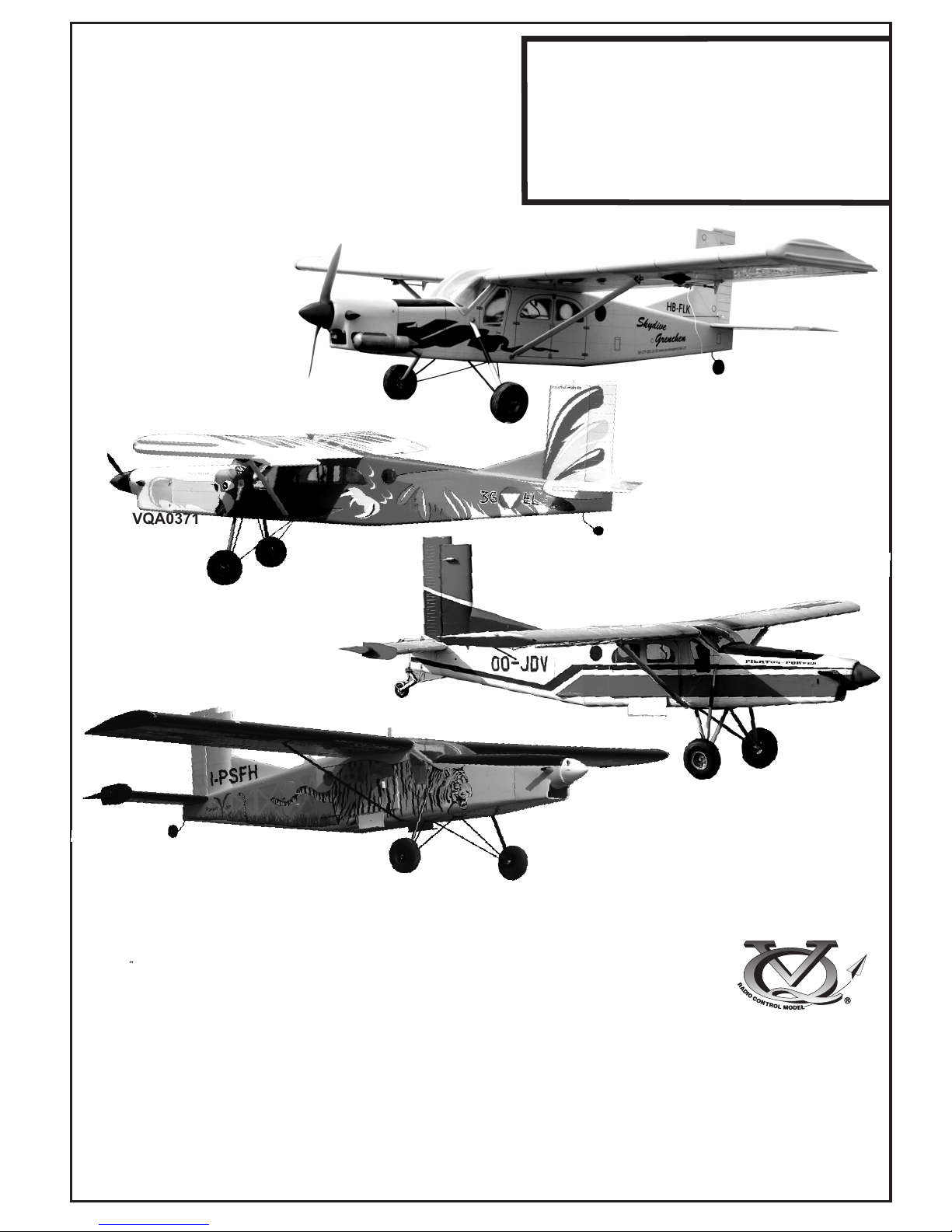
PILATUS PORTER
PC-6
MONTAGEANLEITUNG
VQA0371
INSTRUCTION MANUAL
VQA037Y
VQA036W
SPECIFICATIONS
Wingspan 1580mm
Length 1160mm
Electric Motor 870 Watt (PULSAR 60)
Glow Engine .46 2-T / .70 4-T
Radio 5 Channel / 5 Servos
WARNING! This radio controlled model is NOT a toy. If modified or flown carelessly it could go out of controll and
cause serious human injury or property damage. Before flying your airplane, ensure the air field is spacious enough.
Always fly it outdoors in safe areas and seek professional advice if you are unexperienced.
ACHTUNG! Dieses ferngesteuerte Modell ist KEIN Spielzeug! Es ist für fortgeschrittene Modellflugpiloten bestimmt,
die ausreichende Erfahrung im Umgang mit derartigen Modellen besitzen Bei unsachgemäßer Verwendung kann
hoher Personen- und/oder Sachschaden entstehen. Fragen Sie in einem Modellbauverein in Ihrer Nähe um
professionelle Unterstützung, wenn Sie Hilfe im Bau und Betrieb benötigen. Der Zusammenbau dieses Modells ist
durch die vielen Abbildungen selbsterklärend und ist für fortgeschrittene, erfahrene Modellbauer bestimmt.
TECHNISCHE DATEN
Spannweiter 1580mm
Lange 1160mm
Elektroantrieb 870 Watt (PULSAR 60)
Verbrennerantrieb 7.5cc 2-T / 11cc 4-T
Fernsteuerung 5 Kanal / 5 Servos
VQA0361
46 Class
52 Class
(2T engine)
(4T engine)
Or Electric equivalent
Radio control model / R/C Flugmodel
.........................................................
.........................................................
.........................................................
.........................................................
.........................................................
.........................................................
.........................................................
.........................................................
.........................................................
.........................................................
.........................................................
1.5mm
A
B
!
CA
L/R
Assemble left and right
sides the same way.
X
Drill holes using the stated
size of drill
(in this case 1.5 mm Ø)
Use epoxy glue
Take particular care here
Hatched-in areas:
remove covering
film carefully
Not included.
These parts must be
purchased separately
Check during assembly that these
parts move freely, without binding
Apply cyano glue
SILICON
EPOXY A
EPOXY B
CA
Epoxy Glue (30 minutes type)
Silicon Glue
Cyanoacrylate Glue
Sekundenkleber
Epoxy-Klebstoff (30min)
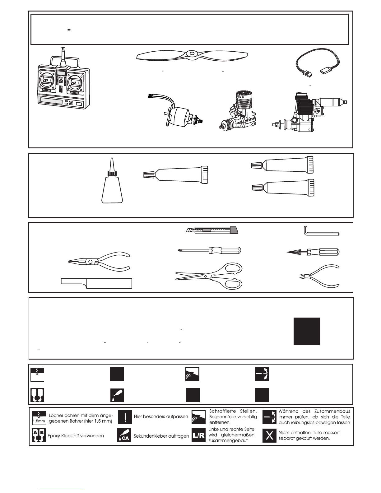
Minimum 5 channel radio
for airplane
.52 cu.in (8.5cc)
Extension cord
.46 cu.in. (7.5cc)
REQUIRED FOR OPERATION (Purchase separately)
Minimum 5 Kanal
Fernsteuerung
Servoverlangerungskabel
BENOTIGTE KOMPONENTEN (Nicht im Lieferumfang enthalten)
Propeller 11x8 for electric motor / 11x6 for glow engine
Luftschraube 11x8 fur Elektromotor / 11x6 fur Verbrennungsmotor
Brushless Motor
PICHLER BOOST 40
Brushless ESC
Brushless Regler
Battery / Flugakku LEMONRC 3700-11.1V
Silikonkleber
Tool Required/ Erfoderliches Werkzeug
The pre-covered film on ARF kit may wrinkle due to variations of temperature.
Store model in a cool and dry place for awile.
Then, staring with low heat, you may carefully use a hair dryer to smooth out wrinkels.
Die Bespannung des Modells kann durch Temeratureinflusse erschlaffen oder Falten
werfen z.b bei zu starker Sonnenenstrahlung oder Hitze.
Stellen Sie das Modell zunachst an einen kuhlen Platz fur eine bestimmte Zeit. Danach
konnen Sie versuchen die restlichen Falten vorstichtig mit einem Haartrockner zu behandeln.
!
CONVERSION TABLE
1.0mm = 3/64”
1.5mm = 1/16”
2.0mm = 5/64”
2.5mm = 3/32”
3.0mm = 1/8”
4.0mm = 5/32”
5.0mm = 13/64”
6.0mm = 15/64”
10mm = 13/32”
12mm = 15/32”
15mm = 19/32”
20mm = 51/64”
25mm = 1”
30mm = 1-3/16”
45mm = 1-51/64”
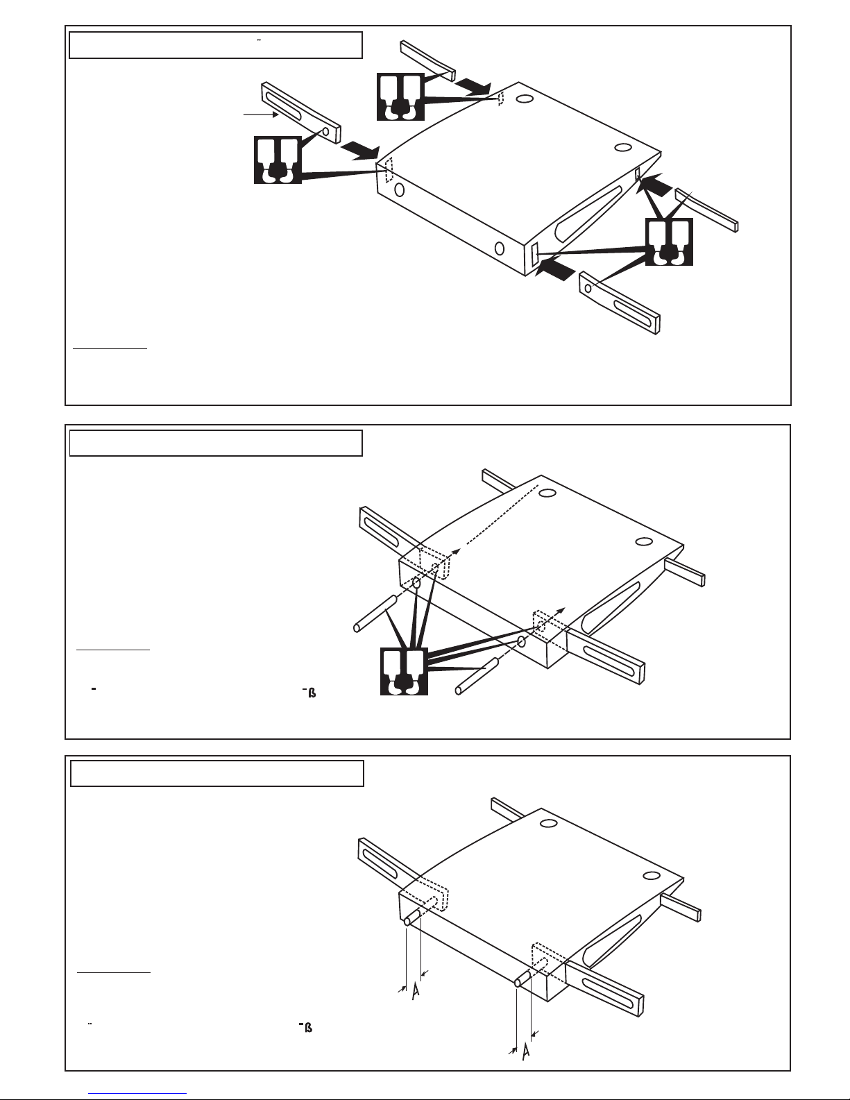
WARNING!: Securely glue together, if coming of
during flights, you lose control of your plane
which lead to accidents.
1-Trial fit each part before gluing . Be certain
that there are no gaps. If the parts will join,
but with a gaps, sand or trim the parts a little
at a time until the parts meet exactly with no
gaps.
2-Check for the correct dihedral angle
3-When joining the wing halves it is extremely
important to use plenty of epoxy (30 minutes
epoxy).
1- Wing Joiner / Flachenverbinder
A
B
A
B
A
B
6mm plywood
3mm plywood brace
6mm plywood brace
TOP VIEW / Draufsicht
Trial fit each part before gluing . Be certain
that there are no gaps. If the parts will join,
but with a gaps, sand or trim the parts a little
at a time until the parts meet exactly with no
gaps.
WARNING!: Securely glue together, if coming of
during flights, you lose control of your plane
which lead to accidents.
A
B
7mm diameter wooden dowel
A = 10mm
WARNING!: Securely glue together, if coming of
during flights, you lose control of your plane
which lead to accidents.
Tragflächenverbinder
Tragflächenverbinder
Tragflächenverbinder
2- Wing Joiner
/ Flächenverbinder
3- Wing Joiner
/ Flächenverbinder
TOP VIEW / Draufsicht
Die Teile probehalber zusammenstecken
und ggf. Etwas nacharbeiten.
Fuhren Sie die Verklebungen mit gro ter
Sorgfalt aus
TOP VIEW / Draufsicht
Fuhren Sie die Verklebungen mit gro ter
Sorgfalt aus
WARNING: Securely glue together, if coming of
during flights, you lose control of your plane
which lead to accidents.
1-Trial fit each part before gluing . Be certain
that there are no gaps. If the parts will join,
but with a gaps, sand or trim the parts a little
at a time until the parts meet exactly with no
gaps.
2-Check for the correct dihedral angle
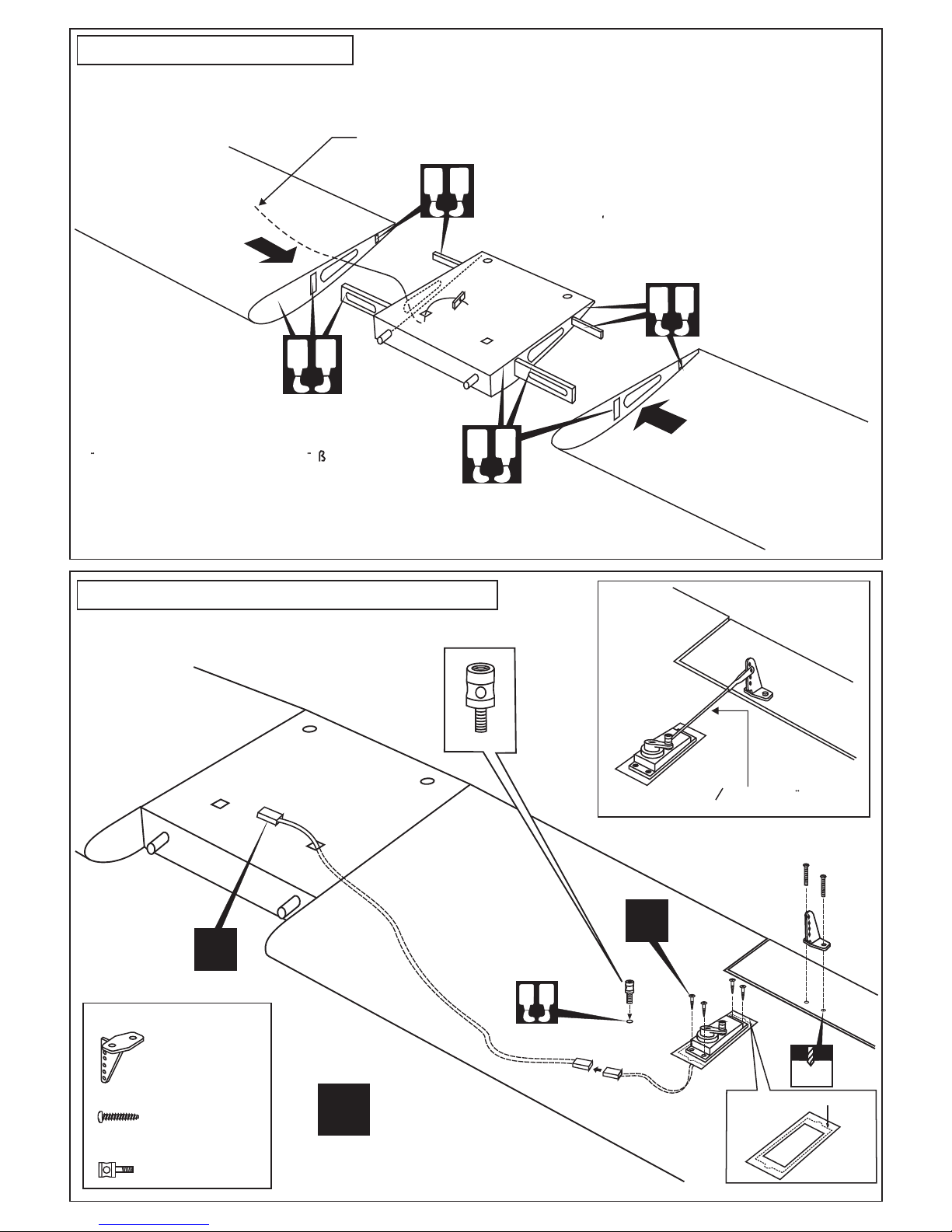
4-Carefully slide the wing halves together,
ensuring that they are accurately aligned,
Firmly press the two halves together, allowing
the excess epoxy run out
3-When joining the wing halves it is extremely
important to use plenty of epoxy (30 minutes
epoxy).
A
B
L/R
Plastic control horn
2x20mm screw
Linkage Stopper set
............................2
......................4
.....................2
A
B
To aileron extension cord
X
A
B
A
B
X
2mm
2x20mm screw
4- Joining the wing
5- Installing the linkages / Einbau RC-Anlage
/ Fläche
Gestängeanschluss
Die Teile probehalber zusammenstecken
und ggf. etwas nacharbeiten.
Fuhren Sie die Verkiebungen mit gro ter
Sorgfalt aus.
1.2mm O Alenk-Gestange
BOTTOM - VIEW / Unteransicht
BOTTOM - VIEW / Unteransicht
Cut here for standard servo
IMPORTANT:
Please do not clean off the excess epoxy on the wing with strong solvent
or pure alcohol, only use kerosene to keep the colour of your model not fade.
A
B
5mm
!
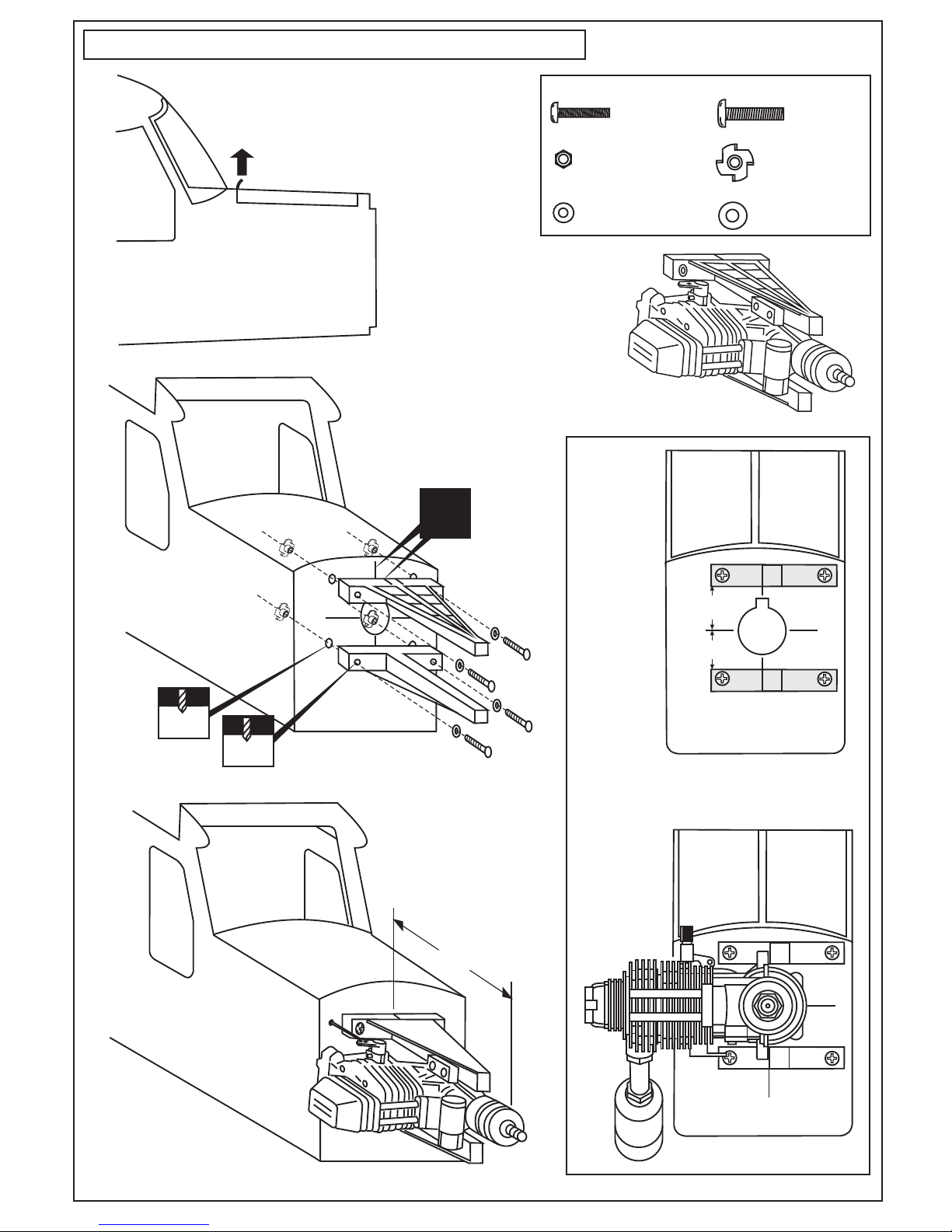
Align the engine center with fire-wall
marked line (A=A’)
Align the mark on both
mounts with the center
mark on the fire-wall
A
A’
FRONT VIEW
FRONT VIEW
In case of 4T engine
Using the four 3x20mm
screws securing the engine
to the engine-mount
B
B=107~110mm
4x25mm screw
Schraube
4mm
............4
.....................4
4x15mm screw
Blind-nut
............4
3x20mm screw
.....................4
3mm nut
3mm washer
.....................4
4mm washer
.....................4
6- Engine - Engine mount /
Motorträger - Motoreinbau
Motorträger
Pull the transparent sticker
to open the hatch.

X
To muffler
Filler tube
To engine
Rubber
stopper
Cap
Stopper
After confirming the direction . Insert and
tighten the screw.
4mm
8- Fuel tank /
Kraftstofftank
zum Motor
Überlauf
Tanken
In case of 4T engine
In case of 2T engine
Align the mark on both mounts
with the center mark on the fire-wall
!
A
A’
Align the engine center with
fire-wall marked line (A=A’)
FRONT VIEW
7- Engine - Engine mount /
Motorträger - Motoreinbau
Viertaktmotoren
Zweitaktmotoren
Motorträger
Engine mount
F2
For Gas power
FUEL TANK
Cut the opening (C)
for fuel-tank installation.
F2
Note: Do not cut here in case of
Electric power.
(C)
(C)
(C)
(C)

9- Brushless Motor
Firewall
107~110mm
B’
B
B=B’
A
A=A’
A’
TOP-VIEW / Draufsicht
SIDE-VIEW / Seitenansicht
FRONT-VIEW
4mm
5/32”
! Align with the marks
3mm
1/8”
1
3
4
Plywood motor mounting plate (2pcs)
Aluminum motor
mounting plate
2
5
6
7 - 8
Magnetic piece
F2
9
Sperrholztrager Platten (2 St.)
Vorderansicht
An den Markierungen ausrichten
! Align with the marks
An den Markierungen ausrichten
Sperrholztrager Platten zusammenkleben, wie gezeigt ausrichten
und Locher bohren.
Motor nach untenstehendem Schema einbauen.
Fur optimale Leistung empfehlen wir folgende Komponenten:
-Brushless-Motor PICHLER BOOST 40
-Brushless Regler PICHLER ESC-60
-LiPO Akku LEMONRC 3700-11,1V
-Luftschraube 11x8
Glue Plywood motor mounts together, align with the firewall
as show. Install motor as show below.
For maximum performance, we recommended the following:
-Brushless-Motor PICHLER BOOST 40
-Brushless Regler PICHLER ESC-60
-LiPO Battery LEMONRC 3700-11,1V
-Luftschraube 11x8
Montagekreuz aus
Alu (nicht enthalten)
Magnet
Battery hatch
Akkuklappe
Motorspant
Note the side thrust for motor!
Sturz und Zug beachten!
X4 X16
X12
X4

Trim the cowling so it will
match your engine
2 mm
1.5mm
3x8mm screw
..............4
10- Cowling /
Motorhaube
Blechschraube
FUSELAGE - TOP VIEW / UNTERANSICHT
Secure foam padding with rubber bands or tape
(must be purchased separately)
Receiver and battery
BATTERY
L
R
2
4
6
8
10
20
30
40
50
H
L
0
2
4
6
8
10
12
-2
-4
4
6
8
10
12
16
14
18
40
60
80
100
120
160
140
180
N
W
E
S
3
6
9
12
15
18
21
24
27
33
36
39
400
500
600 100
300
200
60
0
2
4
6
8
10
12
-2
-4
40
60
80
100
120
160
140
180
BAT
Elevator
servo
Rudder
servo
Throttle
servo
X
Pushrod
3mm set Screw
2 mm
Linkage Stopper set
.....................3
.....................3
3mm set screw
11- Linkage / Anlenkungen
Akku &
Empfänger
in Schaum lagern
Rudergestänge
Gestängeanschluss
Höhenruderservo
Seitenruderservo
Drosselservo
Madenschraube M3
Madenschraube M3
Falls ein Verbrennungsmotor eingebaut
wird mu die Motorhaube entsprechend
dem Zylinder ausgeschnitten werden.

Nylon strap
4mm Main landing
gear
2.5mm landing
gear
Aluminum tube
Stopper (metal)
Collar
Collar
3x12mm screw / Schraube
..................................................2
Spring
.........................................................2
Main landing gear (4mm).................2
Landing gear (2.5mm)......................2
12- Landing gear / Fahrwerk
3x12mm screw
............................10
Nylon strap
.......................5
Stopper (metal)
..........................2
.........................4
3mm set screw
3x12mm screw
3mm set screw
Aluminum tube
13- Landing gear / Fahrwerk
Kunststoffstreifen
Kunststoffstreifen
Madenschraube M3
Stellring
Hauptfahrwerk
Fahrwerksdraht
Fahrwerksdraht
Hauptfahrwerk

Cut away only the film on the
bottom of the horizontal stabilizer
Cut away only the
film both the left
and right side
A
B
A
B
Elev. / Rudd.
Plastic control horn
A
A’
A=A’
B
B’
B=
B’
Plastic control horn
and back plate
2x12mm screw
.....1
...........2
WARNING! Securely glue together.
If coming off during flights, you lose
control of your airplane which leads
to accidents !
.....................4
Washer
............4
3x15mm screw
.....................4
Nut
FUSELAGE - REAR - BOTTOM VIEW
SIDE VIEW
2 mm
14- Tail gear / Heckspornrad
2x12mm screw
FUSELAGE - TOP-VIEW
AUFSICHT
BOTTOM
TOP
16- Vertical Tail / Seitenruder
Bespannfolie an den
Klebestellen vorsichtig
entfernen.
15- Horizontal Tail / Hohenruder
FUSELAGE - TOP-VIEW
AUFSICHT
Fuhren Sie die Verklebungen mit gro ter
Sorgfalt aus.
* WARNING: When removing any covering from
the airframe, please ensure that you secure the
cut edge with CA or similar cement. This will
ensure the covering remain tight.
* WARNING: When removing any covering
from the airframe, please ensure that you
secure the cut edge with CA or similar
cement. This will ensure the covering
remain tight.

A
B
Plastic control horn
and back plate
2x12mm screw
.....1
...........2
CA
2 mm
FUSELAGE - REAR - BOTTOM VIEW / UNTERSICHT
17- Rudder / Ruderinstallation
2x12mm screw
18- Linkage / Ruderanlenkung
19- Hatch
Rudder servo / Seitenruder servo
Elevator servo / Hohenruder servo

Collar / Gewindestift
....................2
2x12mm screw / schraube
................4
2x12mm screw
3x3mm
set screw
Linkage Stopper set
.....................4
CA
CA
20- Hatch
.........2
6x38 Nylon screw
70 ~ 75mm
20mm
10mm
10mm
10mm
Aileron
Rudder
Elevator
22- Balance / Schwerpunkt
10mm
20mm
Gewindestift
2mm ID collar
Spornrad 30mm
CA
21- Wing installation / Flachenbefestigung
Querruderausschlag
Hohenruderausschlag
Seitenruderausschlag
Do not try to fly an out-of balance model!
Uberprufen Sie vor dem Flug den Schwerpunkt.

23- Decoration / Aufkleber
Note: Cut out the stickers and apply them in the proper area. Do not peel the backing paper off all at once.
Peel off one corner of the backing and cut off with scissors. Arrange sticker on model and when satisfied
adhere the corner without backing.
Carefully peel back the rest of the backing while at the same time adhering the rest of the sticker.
Try not to make air bubbles, if there are some, carefully puncture sticker (center of bubble) but not model
surface with the tip of the knife or sharp pin and squeeze out the air. At curves stretch sticker and apply a little
heat so that no ceases occur. Cut off the excess that is produced.
L/R
1
L/R
CA
2
YELLOW SCHEME
Sticker
L/R
Sticker
Sticker
VQA037Y
YELLOW SCHEME
L/R
Sticker
WHITE SCHEME
L/R
Sticker
Sticker
CA
Antenna (plywood)
VQA037W
VQA037Y
VQA037Y / VQA037W / VQA0371
VQA037Y / VQA037W / VQA0371

24- Decor / Aufkleber
L/R
Sticker
VQA0371
L/R
Sticker
VQA0371
3G
EL
A
B
25- Decor / Aufkleber
Sticker
BIRD VERSION
SWISS VERSION
VQA0362

3x3mm
set screw
CA
CA
CA
Wing brace
WARNING: Never fly your model without wing brace installed because the wing of your model
may be break when you fly with high speed or a strong wind.
WARNING: Securely glue together, if coming of
during flights, you lose control of your plane
which lead to accidents.
Joining the wing
/ Fläche
Fuhren Sie die Verkiebungen mit gro ter
Sorgfalt aus.
Cut away only the cover
before glue the wing together
( Steep 4 )
Cut away only the cover
before glue the wing together
( Steep 4 )
WARNING
WARNING

All details are subject to change
without notice !
Technische Anderungen und Irrtumer
vorbehalten !
BEFORE FLYING CHECK EVERYTHING
Before each flight, inspect the airplane for any loose parts. Check the hinges, make sure the pushrods are still firmly
attached, and check the engine mounting bolts. In general, check everything on the plane that might possibly come
loose.
CHECK THE FREQUENCE BEFORE FLYING
DO NOT FLY NEAR A POWER LINE
The power lines cause radio interference, so avoid flying near them.
Adjust the engine always from behind, but never from infront or the sides as rotating propeller may badly injure you!
Do not allow watching people to get too close to a rotating propeller.
Ensure the spinner and propeller are securely attached. Immediately disure defective propeller as well as deformed
spinners.
Be sure to keep an adequate supply of fuel in the tank. Don’t continue to fly the model until the tank is drained dry.
Never fly directly over people or fly directly towards people.
This model is highly pre-fabricated and can be built in a very short time. However, the work which you have to carry
out is important and must be done carefully. The model will only be strong and fly well if you complete your tasks
competently - so please work slowly and accurately.
SAFETY NOTES AND WARNINGS RELATING TO MODEL AIRCRAFT POWERED BY GLOWPLUG ENGINE
Always take off and landing your airplane into the wind.
Fully extend the transmitter and receiver antenna.
Switch off the transmitter and receiver after landing.
Ensure the airfield is spacious enough.
WARNING !
Do not put in a large-than recommended engine. A bigger engine does not necessarily mean better performance.
IMPORTANT:
Please do not clean your model with pure alcohol, only use liquid soap with water or use glass cleaner
to clean on surface of your model to keep the colour not fade.
 Loading...