

Page 1
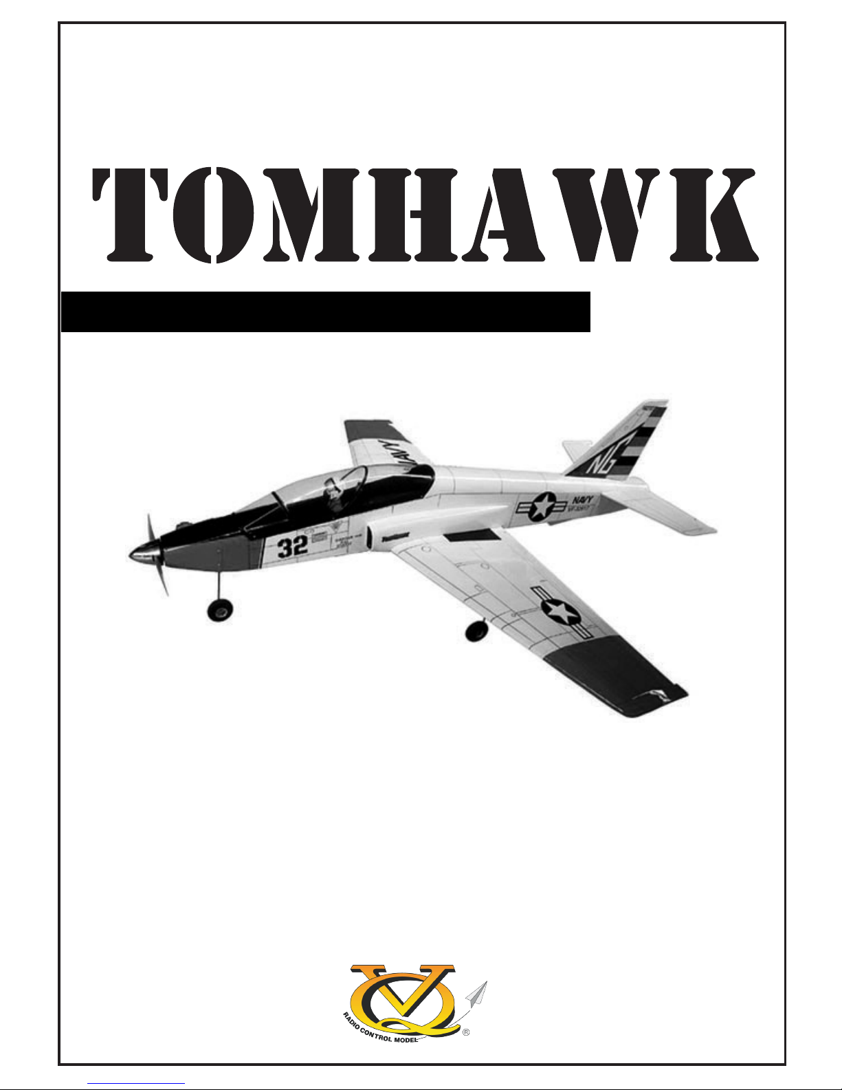
Sport “ JET”
VQA023
SPECIFICATIONS
Wingspan 1372mm
Electric Motor 870 Watt (PULSAR 60)
Glow Engine 46 2-T
Radio 4 Channel / 4 Servos
TECHNISCHE DATEN
Spannweite 1372mm
Elektroantrieb 870 Watt (PULSAR 60)
Verbrennerantrieb 7.5cc 2-T
Fernsteuerung 4 Kanal / 4 Servos
Instruction manual /
Montageanleitung
RADIO CONTROL MODEL / RC FLUGMODELL
ALL BALSA, PLYWOOD CONSTRUCTION AND ALMOST READY TO FLY
WARNING! This radio controlled model is NOT a toy. If modified or flown carelessly it could go out of controll and
cause serious human injury or property damage. Before flying your airplane, ensure the air field is spacious enough.
Always fly it outdoors in safe areas and seek professional advice if you are unexperienced.
ACHTUNG! Dieses ferngesteuerte Modell ist KEIN Spielzeug! Es ist für fortgeschrittene Modellflugpiloten bestimmt,
die ausreichende Erfahrung im Umgang mit derartigen Modellen besitzen Bei unsachgemäßer Verwendung kann
hoher Personen- und/oder Sachschaden entstehen. Fragen Sie in einem Modellbauverein in Ihrer Nähe um
professionelle Unterstützung, wenn Sie Hilfe im Bau und Betrieb benötigen. Der Zusammenbau dieses Modells ist
durch die vielen Abbildungen selbsterklärend und ist für fortgeschrittene, erfahrene Modellbauer bestimmt.
Page 2
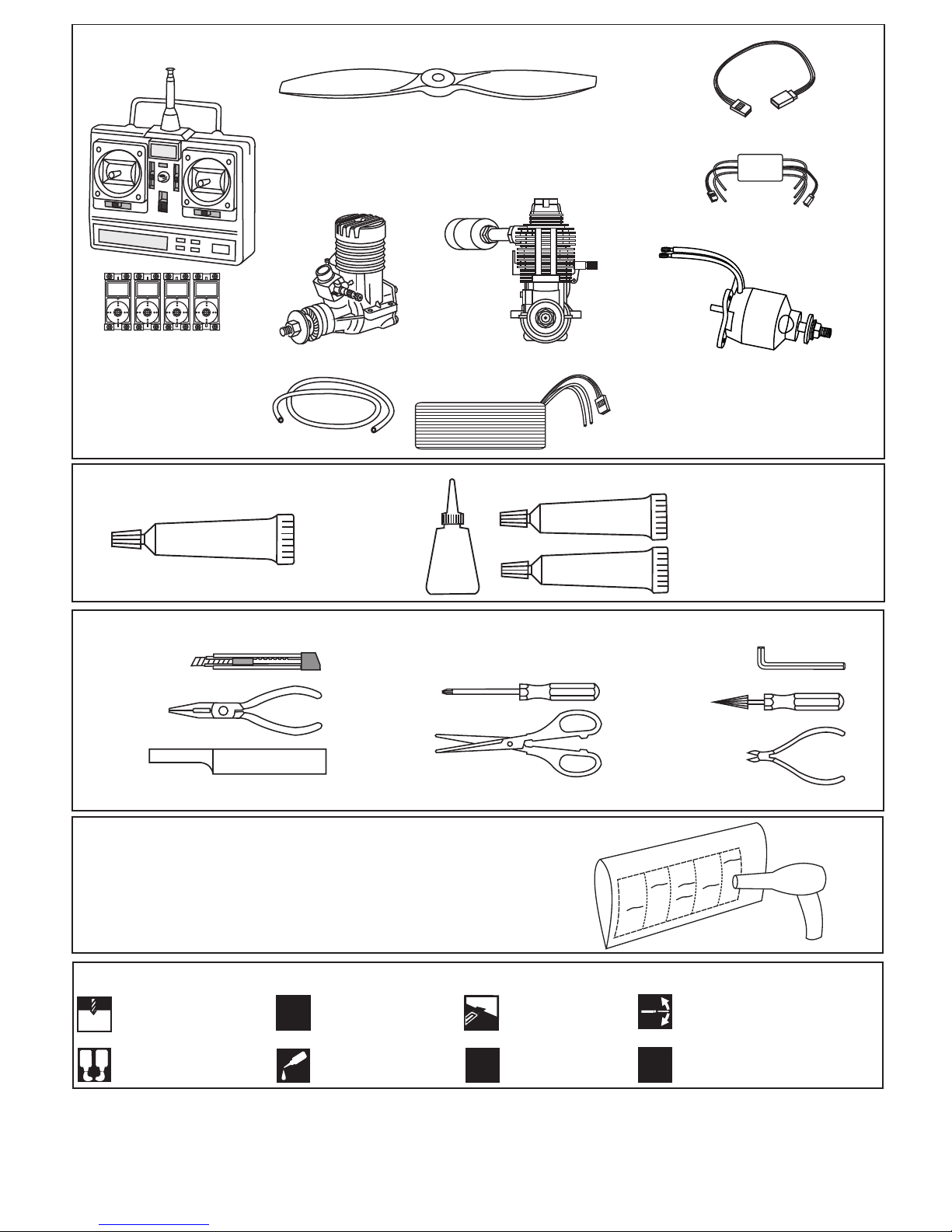
1.5mm
A
B
!
CA
L/R
Assemble left and right
sides the same way.
X
Drill holes using the stated
size of drill
(in this case 1.5 mm Ø)
Use epoxy glue
Take particular care here
Hatched-in areas:
remove covering
film carefully
Not included.
These parts must be
purchased separately
Check during assembly that these
parts move freely, without binding
Apply cyano glue
The pre-covered film on ARF kit may wrinkle due to variations
of temperature. Smooth out as explained right.
* Use an iron or heat gun. Start as low setting. Increase the
setting if necsessary. If it is too high, you may damage the
film
SILICON
EPOXY A
EPOXY B
CA
GLUE
Epoxy Glue ( 5 minute type)
Silicon sealer
Cyanoacrylate
Glue
Minimum 4 channel radio
for airplane with 4 servos
.60 ~.70 - 4 cycle
10.5x6 for .40 - 2 cycle engine
11x6 for .46 - 2 cycle engine
12x6 for .60 - 4 cycle engine
12x7 for .70 - 4 cycle engine
13x6 for Quantum 4120/05
Silicone tube
Extension for aileron
servo, retract servo.
.46 ~ .50 - 2 cycle
REQUIRED FOR OPERATION (Purchase separately)
Epoxy Glue (30 minute type)
TOLLS REQUIRED
Hobby knife
Needle nose Pliers
Phillip screw driver
Awl
Scissors
Wire Cutters
(Purchase separately)
Hex Wrench
.........................................................
.........................................................
.........................................................
.........................................................
.........................................................
.........................................................
.........................................................
.........................................................
.........................................................
.........................................................
.........................................................
Sander
Masking tape - Straight Edged Ruler - Pen or pencil - Rubbing alcohol - Drill and Assorted Drill Bits
Read through the manual before you begin, so you will have an overall idea of what to do.
Symbols used throughout this instruction manual, comprise:
(Purchase separately)
.Motor control x1 .Aileron x1
.Elevator x1 .Rudder x1
Quantum 4120/05
Brushless Motor
or equivalent.
Phoenix-60 Brushless
Motor Control
Li-Po Battery, 14.8V, 4000mAH, 80A
CONVERSION TABLE
1.0mm = 3/64”
1.5mm = 1/16”
2.0mm = 5/64”
2.5mm = 3/32”
3.0mm = 1/8”
4.0mm = 5/32”
5.0mm = 13/64”
6.0mm = 15/64”
10mm = 13/32”
12mm = 15/32”
15mm = 19/32”
20mm = 51/64”
25mm = 1”
30mm = 1-3/16”
45mm = 1-51/64”
Page 3
BOTTOM VIEW
3/32”
BOTTOM VIEW
BOTTOM VIEW
Bend wire for
smooth retracting
....X 8
3x10mm screw
1- RETRACT LANDING GEAR
2- RETRACT LANDING GEAR
3- RETRACT LANDING GEAR
11/64 in.(4.2mm) I.D collar
L/R
L/R
Steel clevis
(3x10) screw
Trial fit the push rod into the wing. Join the pushrod to
the retract gear arm and trial fit the retract into the
wing.
Be sure to adjust the stroke so that the landing gear
locks in both up and down position.
7/8 in.
Attach the wheels on the main gear wries with
11/64 in. I.D wheel collars
WING BOTTOM
To retract servo arm
Retract push rod
............. 4
5/32” (4mm) collar
After checking that the retract works smoothly,
fix the retract on the wing with 3x12mm
self tapping screws.
Do the same way with other half wing.
Put the nylon ring
Retract push rod Retract gear arm
2mm
X
Page 4
A
B
A
B
BOTTOM VIEW
WARNING!: Securely glue together, if coming of during flights,
you lose control of your plane which lead to accidents.
Trial fit each part before gluing . Be certain that there are no gaps.
If the parts will join, but with a gaps, sand or trim the parts a little at a time
until the parts meet exactly with no gaps.
Carefully slide the wing halves together, ensuring that they are accurately
aligned, firmly press the two halves together, allowing the excess epoxy run
out. Clean off the excess epoxy.
When joining the wing halves it is extremely important to use plenty of epoxy
(30 minutes epoxy).
4- JOINING THE WING
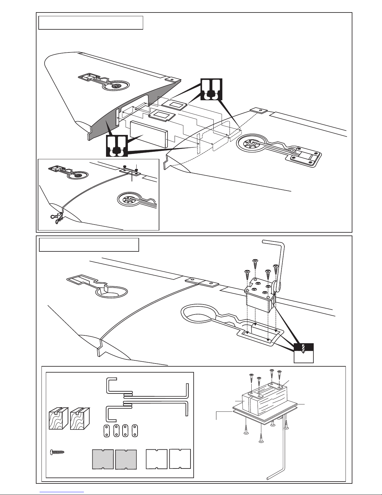
BOTTOM VIEW
Ply gear mount plate
Square plastic
Main gear (left)
Main gear (right)
Gear mount
(hard wood)
Plastic strap
3x10mm ....16
5- FIX GEAR
1
(1)
2
(2)
3
(3)
Plywood brace
Retract servo tray
Aileron servo tray
3x10mm
self tapping screw
Plastic strap
Main landing gear
Gear mount
(hard wood)
Ply gear mount
plate
Square plastic
3x12mm self
tapping screw
3x10mm self
tapping screw
2mm
5/64”
Binder clip
Nylon wing bolt
Rubber band
(both side)
BOTTOM VIEW
IMPORTANT:
Please do not clean off the excess epoxy on the wing with
strong solvent or pure alcohol, only use kerosene to keep the colour of
your model not fade.
Page 5

Retract Push rod
Retract servo
Retract servo
Aileron servo
X
X
X
1.5mm
2 mm
20 ~ 24mm
WING - TOP VIEW
Included with the radio set
6- RETRACT - AILERON SERVO
RETRACTED
EXTENDED
Retract Push rod
Retract Push rod
Retract servo
Aileron servo
Aileron Push rod
Retract gear
Retract gear
7- INSTALLING THE LINKAGES
1.5mm
A
B
!
CA
L/R
Assemble left and right
sides the same way.
X
Drill holes using the stated
size of drill
(in this case 1.5 mm Ø)
Use epoxy glue
Take particular care here
Hatched-in areas:
remove covering
film carefully
Not included.
These parts must be
purchased separately
Check during assembly that these
parts move freely, without binding
Apply cyano glue
WING - TOP VIEW
Link the retract push rod to the retract servo.
Be sure to adjust the stroke so that the landing
gear locks in both up and down position.
With the retract and retract servo in the retracted position,
mark the position where each of the pushrod will attach to
the servo arm, a small piece of masking tape works well
for this. Cut off the excess length each rod.
Page 6

!
! Engine thrust on balk head
is already adjust at factory
3x20mm screw
4x15mm screw
Washer.............4
Blind nut.......4
................4
..............4
Washer............4
Nut.............4
8- ENGINE MOUNT - NOSE GEAR MOUNT
Nose gear
mount
Engine mount
FIRE WALL
1
2
3
4 - 5
Nose gear control horn
Nose gear
mount
1-Secure attach the engine
mount to the fire wall
using the four 4x25mm
screws
2-Cut away right side of
the nose gear mount as show.
3-Secure attach the nose gear mount to the
fire wall using the four 3x20mm screws.
4-Insert the Z-bend of nose gear pushrod
into the hole on the nose gear control horn.
5-Insert the nose gear control horn into the nose
gear mount.
6-Slide the nose gear into the nose gear mount.
! Align the mark on both
mounts with the mark on
the fire wall
FRONT-VIEW
9- NOSE RETRACT LANDING GEAR
FRONT-VIEW
FIRE WALL
Link the pushrod with retract
arm servo
Link the pushrod with rudder
arm servo
1/4 in. (6mm)
thick plywood
Nose retract landing
gear mount
X
X
X
6
5mm
13/64”
Page 7

11- FUEL TANK
After confirming the direction . Insert this assembly, clunk
end first, into the fuel tank and tighten and screw the
fuel tank cap on firmly
3x30 mm screw
5/32 in. (4mm)
X
To muffler
Filler tube
To engine
Rubber
stopper
Cap
Stopper
X
6.5
FUSELAGE TOP-VIEW
FUSELAGE
FRONT-VIEW
Silencer
10- ENGINE (2 CYCLE)
A=4-9/32” ~ 4-23/64”
(108~110mm)
Page 8

14- HORIZONTAL STABILIZER
Trial fit the horizontal stabilizer in place on the
fuselage. Check the alignment of the horizontal
stabilizer by measuring from a fixed point along
the center line of the fuselage to the leading edge
on each side of the horizontal stabilizer. The
distance must be equal on both sides.
Using the pencil trace around the top and bottom
of the stabilizer where it meets the fuselage.
Remove the horizontal stabilizer from the fuse lage. Remove the covering material from over
both the precut elevator servo and rudder torque
rod holes and from the gluing surfaces on both
the top and bottom of the horizontal stabilizer.
A
A’
B
B’
T pin
A = A’
B = B’
12- HORIZONTAL STABILIZER
Cut away only the covering
both the top and bottom side
13- HORIZONTAL STABILIZER
NOTE: Do not glue the horizontal stabilizer into the
fuselage at this time.
Cut two 7/8” (22mm) long slots along
the hinge line in the trailing edge of
the horizontal stabilizer for the two
elevator torque rod bearings. Position
one slot on each side of the horizontal
stabilizer, 1”(25mm) out from the
centerline.
Test-fit the two elevator torque rods
into the slot, marking sure that the
threaded portion of each torque rod is
toward the bottom of the horizontal
stabilizer.
NOTE: You may need to open up the slots so that
the torque rod bearing are not too difficult to push
in
Cut away the covering material from over the
precut elevator torque rod mounting slot in
each elevator half.
Drill a 1/8”(3mm) diameter hole in each torque
rod mounting slot, marking sure that you drill
the hole perpendicular to the leading edge of
the elevator half.
Position each hole 1-3/16” (30mm) out from
the edge of the elevator half.
Thread one nylon adjustable control horn onto the end
of each elevator torque rod, making sure that the
adjustable control horn face forward.
Test-fit one torque rod into each elevator half. Each
torque rod should fit firmly in the precut groove and
the outer surface of the torque rods should be nearly
flush with the leading edge of the elevator halves.
When satisfied with the fit and alignment, remove the
torque rods and set them aside for now.
=1-3/16”(30mm)
A
A
1/8 in.
3mm
Page 9

Slide the horizontal stabilizer partially into the
fuselage, marking sure that the top of the horizontal stabilizer is toward the top of the fuselage.
Apply a thin layer of petroleum jelly to only the
pivot point of the torque rod bearing, then slide
the adjustable control horn through the side of
the fuselage and glue the torque rod bearing
into the slot you cut previously in the horizontal
stabilizer, using a thin layer of 5 minute epoxy.
A
B
After the epoxy sets up. Pull the horizontal stabilizer through the other side of the fuselage and
repeat the previous procedures to glue the second
torque rod wire into the horizontal stabilizer.
Realign the horizontal stabilizer, then glue the
horizontal stabilizer into the fuselage, using a
generous amount of thin CA. Apply thin CA to each
of the four joints and use a generous amount to
ensure to strong bond.
The elevator hinges are preglue into the elevator
halves. Working with one elevator half for now,
apply a thin layer of petroleum jelly to only the
pivot point of the two hinges.
Slide a small piece of waxed paper between the
torque rod and the horizontal stabilizer to prevent
gluing the torque rod solid.
CA
Without using glue yet, push the elevator half and its
hinges into the hinge slots in the trailing edge of the
horizontal stabilizer, marking sure that the torque rod
is firmly seated in the slot in the elevator half. There
should be a minimal hinge gap and the end of the
elevator half should not rub against the horizontal
stabilizer.
When satisfied with the fit and alignment, hinge the
elevator half to the horizontal stabilizer, using 5
minute epoxy. Make sure to apply a thin layer of epoxy
to the top and bottom of both hinges and to the inside
the torque rod mounting slot and to the end of the
torque rod itself. Repeat the previous procedures to
hinge the second elevator half to the other side of the
horizontal stabilizer.
15- HORIZONTAL STABILIZER
16- HORIZONTAL STABILIZER
17- ELEVATOR
A
B
Page 10

18- VERTICAL STABILIZER
Rudder torque rod
(long piece)
Rudder push rod
CA
Slide the rudder torque rod into the
fuselage.
Link the rudder torque rod with the
rudder push rod.
Remove the covering material from over both side of
the vertical stabilizer where it meet the fuselage.
Cut away the covering material from over the precut
rudder hinge and rudder torque rod mounting slot.
Realign the vertical stabilizer , ensure that the vertical
stabilizer is perpendicular to the horizontal stabilizer.
Then glue the vertical stabilizer into the fuselage, using
a generous amount of thin CA. Apply thin CA to each of
the two joints and use a generous amount to ensure to
strong bond.
Apply a thin layer of petroleum
jelly to only the pivot point of the
torque rod bearing.
Glue the rudder torque rod bearing
into the slot you cut previously in
the vertical stabilizer, using a thin
layer of 5 minute epoxy.
19- VERTICAL STABILIZER
20- RUDDER
Without using glue yet, push the rudder and its hinges
into the hinge slots in the trailing edge of the vertical
stabilizer. There should be a minimal hinge gap and the
end of the rudder should not rub against the vertical
stabilizer.
When satisfied with the alignment, mark the mounting
hole position, where the rudder torque rod meets the
rudder with a pencil.
Remove the rudder and drill a 1/8”(3mm) diameter
hole in torque rod mounting slot, making sure that you
drill the hole perpendicular to the leading edge of the
rudder.
CA
NOTE: You may need to open up the slots
so that the torque rod bearing are not too
difficult to push in.
Cut away the covering material from over the precut
rudder torque rod mounting slot.
1/8 in.
3mm
Cut away only the
covering material
A
B
Cut away only the
covering material
Page 11

Rudder servo (not include)
To nose gear horn
To engine
To nose
retract
Rudder push rod
Cut away the cowl to clear
the engine head
3/32” (2~3mm)
Spinner
FUSELAGE - BOTTOM VIEW
Throttle servo (not include)
Retract servo (not include)
2.5x10mm self
tapping screw
Connector
Elevator servo (not include)
FUSELAGE - BOTTOM VIEW
Elevator control
horn
21- LINKAGES
Rudder push rod
Rudder control horn
22- LINKAGES
23- COWLING
1.5mm
1/16”
2.5x10mm.....4
Page 12

25-CANOPY
Secure the canopy in place
using the six 2x5mm self
tapping screws included the
hardware bag.
CA
26- BATTERY
Battery pack
Securely attach the battery. If
coming off during flights, you
lose control of your plane which
leads to accidents.
2x5mm screw
...............6
BOTTOM VIEW
24- MAIN WING
Plastic cover
CA
6x45mm nylon screw
1/4 in.
6.3mm
Attach the hatch in place and
secure it with four 3x10mm
self tapping screws.
3x10mm screw
...............4
3/64”
1mm
5/64”
2mm
Apply CA glue into the
screwed hole to make
reinforcement.
Page 13

28- CONTROL SURFACE THROW SETTING
CG
WARNING ! Securely install the receiver and power
pack, ensuring they will not come loose or rattle during
flight.
If necessary, add weight to either the tail or nose until
the correct balance is achieved.
Never fly before checking the Cg’s required position.
In order to obtain the CG specified, reposition the receiver and power pack
5-11/16”(144mm)
5~8mm
30mm
AILERON STROKE ELEVATOR STROKE
RUDDER STROKE
8~10mm
5~8mm
8~10mm
30mm
29- BALANCE
WING CENTER SECTION
27- RECEIVER
FUSELAGE - BOTTOM VIEW
Receiver
BEFORE FLYING CHECK EVERYTHING
Before each flight, inspect the airplane for any loose parts. Check the hinges, make sure the pushrods are still firmly
attached, and check the engine mounting bolts. In general, check everything on the plane that might possibly come loose.
CHECK THE FREQUENCE BEFORE FLYING
DO NOT FLY NEAR A POWER LINE
The power lines cause radio interference, so avoid flying near them.
Adjust the engine always from behind, but never from infront or the sides as rotating propeller may badly injure you!
Do not allow watching people to get too close to a rotating propeller.
Ensure the spinner and propeller are securely attached. Immediately disure defective propeller as well as deformed
spinners.
Warning!
IMPORTANT:
Please do not clean your model with pure alcohol, only use liquid soap with water or use glasscleaner to clean on surface of your model to keep the colour not fade.
 Loading...