

Page 1
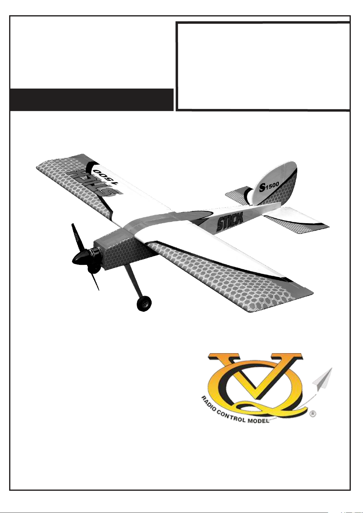
Radio control model
45 Class
60 Class
Or Electric equivalent
INSTRUCTION MANUAL
(2T engine)
(4T engine)
STICK
F - 1500
SPECIFICATIONS
Wingspan 60 in.
Length 38.5 in.
Electric Motor 650 Watt
Glow Engine .45 2-T / .60 4-T
Radio 5 Channel / 5 Servos
WARNING! This radio controlled model is NOT a toy. If modified or flown carelessly it could go out of controll and
cause serious human injury or property damage. Before flying your airplane, ensure the air field is spacious enough.
Always fly it outdoors in safe areas and seek professional advice if you are unexperienced.
Page 2
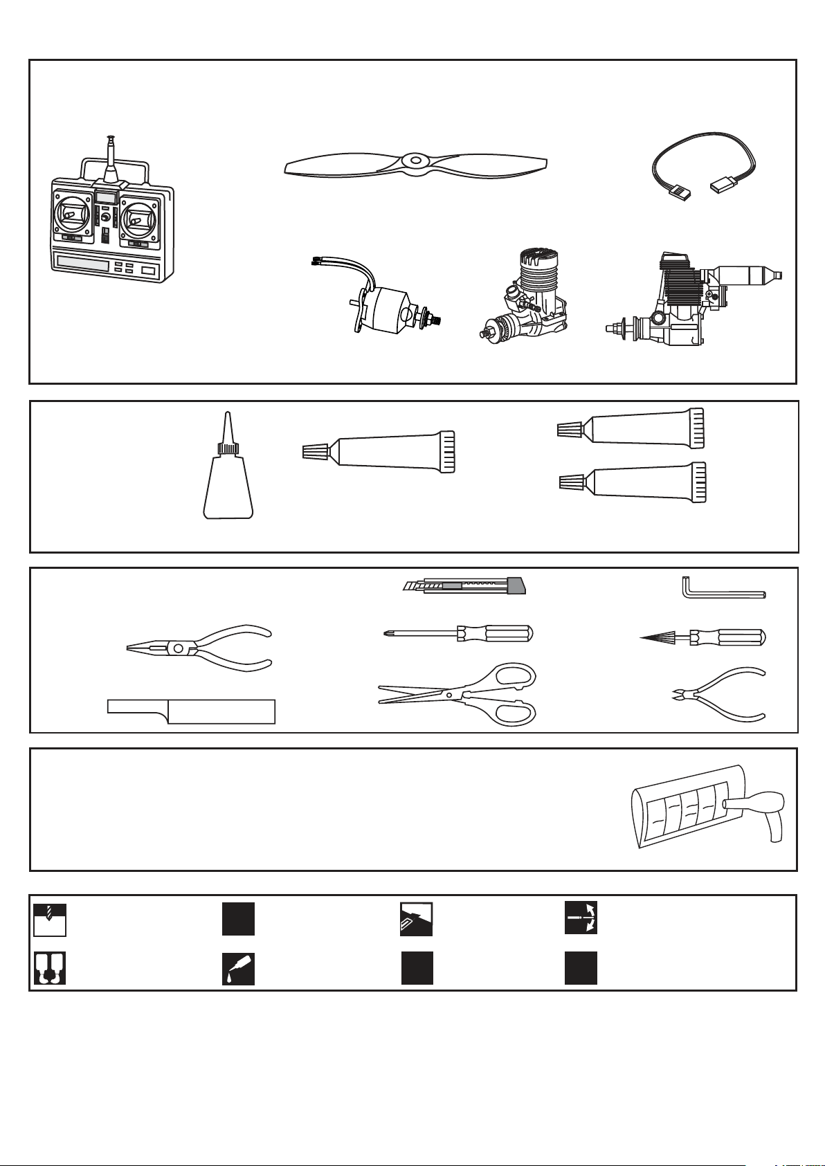
REQUIRED FOR OPERATION (Purchase separately)
Propeller 11x8 for electric motor / 11x6 for glow engine
Extension cord
Minimum 5 channel radio
for airplane
Cyanoacrylate Glue
Tool Required
.........................................................
.........................................................
.........................................................
.........................................................
.........................................................
.........................................................
.........................................................
.........................................................
.........................................................
.........................................................
.........................................................
Brushless Motor
650 Watt
Brushless ESC
Brushless Regler
Battery 3700mAh-11.1V
CA
SILICON
Silicon Glue
.46 cu.in.
.52 cu.in
EPOXY A
EPOXY B
Epoxy Glue (30 minutes type)
If exposed to direct sunlight and / or heat, wrinkles can appear. Storing the model in a coll
place will let the wrinkles disappear. Otherwise, remove wrinkles in covering film with a hairdryer, starting with low temperature. You can fix the corners by using a hot iron.
Drill holes using the stated
1.5mm
size of drill
(in this case 1.5 mm Ø)
A
B
Use epoxy glue
Take particular care here
!
Apply cyano glue
CA
Hatched-in areas:
remove covering
film carefully
Assemble left and right
L/R
sides the same way.
CONVERSION TABLE
1.0mm = 3/64”
1.5mm = 1/16”
2.0mm = 5/64”
2.5mm = 3/32”
3.0mm = 1/8”
4.0mm = 5/32”
5.0mm = 13/64”
6.0mm = 15/64”
10mm = 13/32”
12mm = 15/32”
15mm = 19/32”
20mm = 51/64”
25mm = 1”
30mm = 1-3/16”
45mm = 1-51/64”
Check during assembly that these
parts move freely, without binding
Not included.
These parts must be
X
purchased separately
Page 3
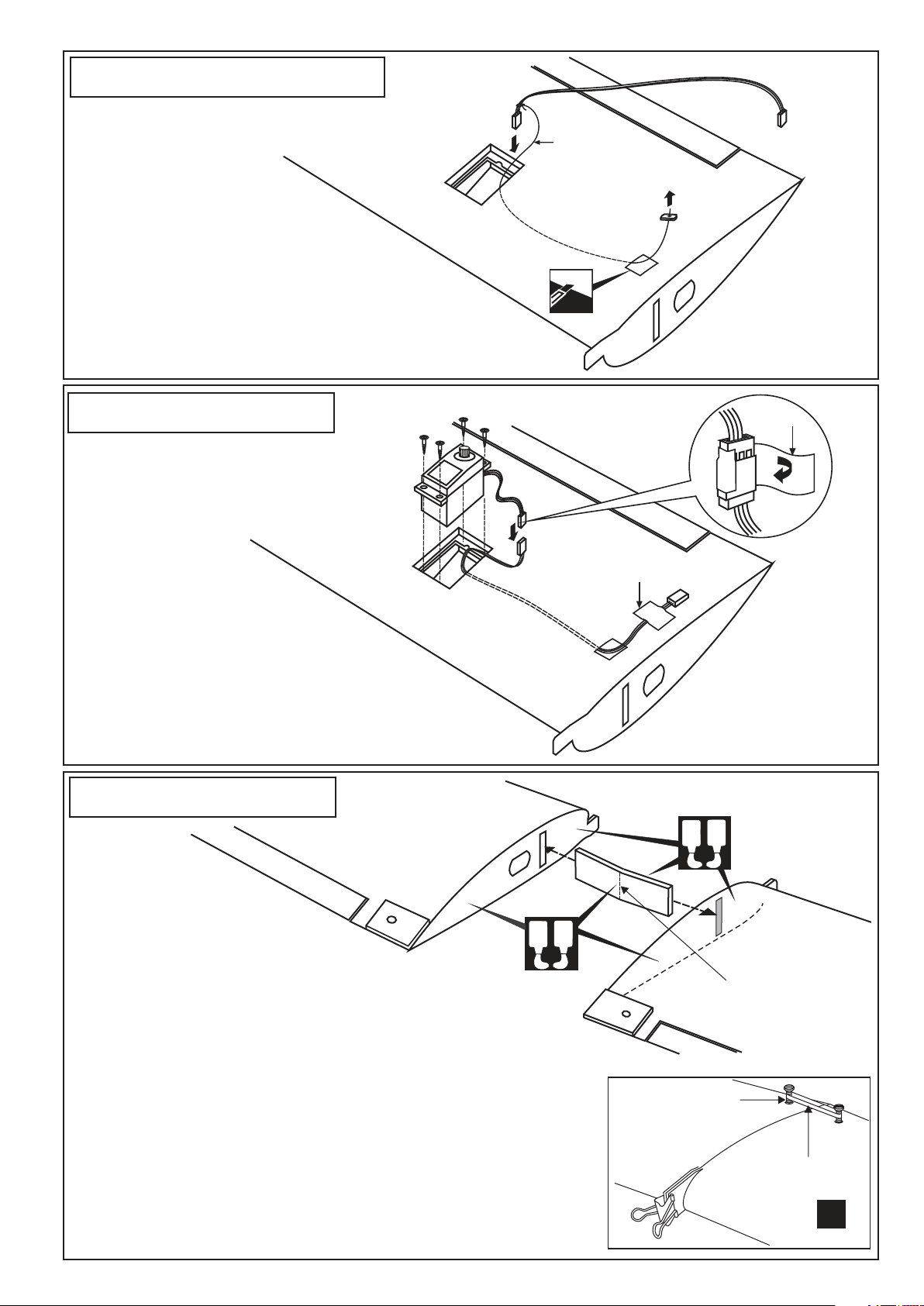
1- Aileron extension cord
WING BOTTOM-VIEW
Cut through both the covering and the balsa
wood of the wing bottom where the aileron
extension cord goes.
Install the servo extension cord in to the wing.
2- Aileron servo
Included with the
radio set.
Cotton thread
(pre-installed in
each wing half)
Aileron extension cord
Adhesive
tape
WING BOTTOM-VIEW
3- Joining the wing
1- Trial fit the wing joiner, into
one of the wing panels. It should
insert smoothly up to the center line
marked. Next, slide the other wing half
onto the dihedral brace until the wing panels
meet. If the fit is overly tight, it may be necessary to lightly sand the
dihedral brace.
A
Adhesive tape
B
WING TOP-VIEW
A
B
Center line
2- Check for the correct dihedral angle
3- Apply a generous amount of epoxy into the wing joiner cavity of one wing
half. Next, Coat one half of the dihedral brace with epoxy up to the center
line. Install the epoxy-coated side of the dihedral brace into the wing joiner
cavity up to the center line.
4- Do the same way with the other wing half. Carefully slide the wing halves
together, ensuring that they are accurately aligned. Firmly press the two
halves together, allowing the excess epoxy to run out. Clean off the excess
epoxy with kerosene (do not use strong sloven or pure alcohol ).
5- Using the binder clip and rubber band to hold the wing together securely
while the epoxy cures.
Nylon wing bolt
(in hardware bag)
Rubber band
(both the top
and bottom)
X
Binder clip
Page 4
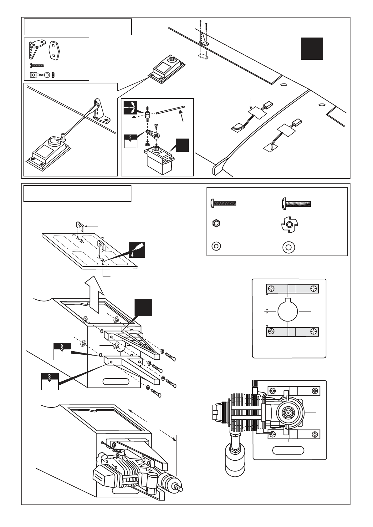
4- Aileron linkage
2x20mm screw
WING BOTTOM-VIEW
..........2
2x20mm.....4
..........2
Aileron pushrod
D=5/64”(2mm)
5- Engine - 4T
TOP-VIEW
3mm set Screw
2 mm
AILERON
SERVO
Handle (3mm ply wood)
Aileron pushrod
D=5/64”(2mm)
X
Adhesive tape
3x20mm screw
............4
3mm nut
.....................4
L/R
4x15mm screw
............4
Blind-nut
.....................4
4mm
5mm
Magnetic hatch
CA
Four holes are pre-drilled at factory
Align the mark on both
mounts with the center
!
mark on the fire-wall
B=100 ~ 105mm
3mm washer
.....................4
Align the engine center with fire-wall
marked line (A=A’)
4mm washer
.....................4
A
A’
FRONT VIEW
B
Using the four 3x20mm
screws securing the engine
to the engine-mount
Page 5
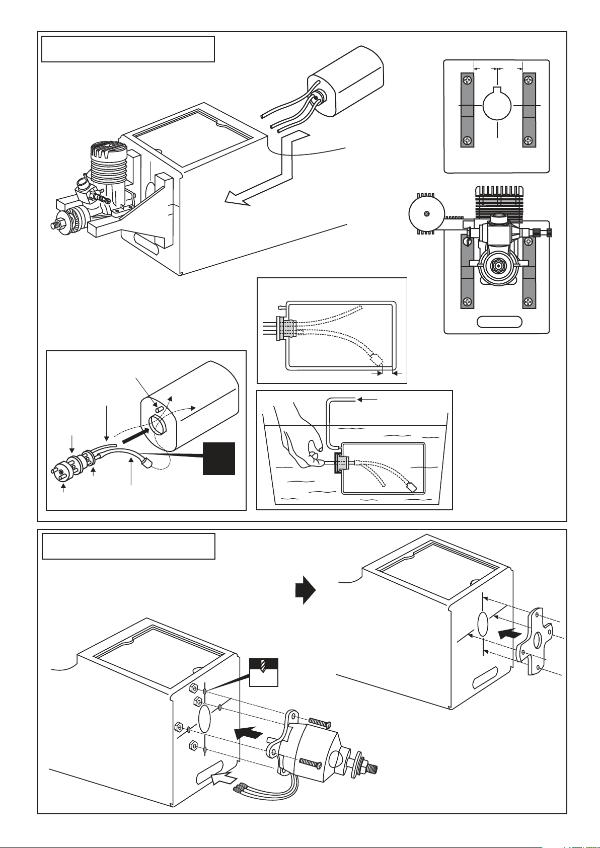
6- Engine - 2T
After confirming the direction . Insert
and tighten the screw.
Align the engine center with
fire-wall marked line (A=A’)
A’
A
FRONT VIEW
1
Rubber
stopper
To muffler
2
Filler tube
X
Stopper
Cap
7- Electric Motor
Using a aluminum motor mounting plate as a template, mark the
Fire-wall where the four holes are to be drilled .
Remove the aluminum motor mounting plate and drill a 1/8”(3mm)
hole through the fire-wall at each of the four marks marked .
Note: The aluminum motor mounting included with electric motor set.
To engine
4mm
Blow
3
Water
Checking for leaks block the vents and blow
into the feed - if in doubt
submersing the tank in a
blow of water will show
up any problems.
3mm
Page 6
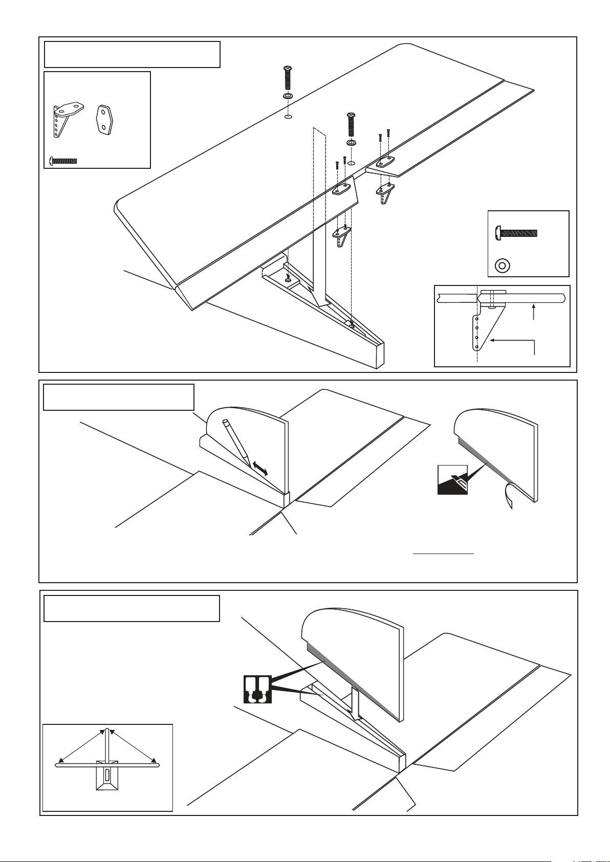
8- Horizontal stabilizer
Plastic control horn
and back plate
.....2
2x12mm screw
...........4
HORIZONTAL STABILIZER
BOTTOM-VIEW
4x20mm screw
...2
4mm washer
.............2
Elev. / Rudd.
FUSELAGE BOTTOM-VIEW
9- Vertical stabilizer
FUSELAGE TOP-VIEW
Trial fit the vertical fin in position. Using
a 90-degree triangle, ensure that the
vertical stabilizer is perpendicular to
the horizontal stabilizer.
10- Vertical stabilizer
Spread epoxy (30 minute) onto the both sides
of the vertical stabilizer along the area where
the covering was removed and to the fuselage
where the vertical stabilizer mounts.
Install the vertictal stabilizer into the fuselage
and adust the alignment as described in steep
9.
Allow the epoxy to cure before proceeding to
next step.
Use a pencil, trace around the vertical
stabilizer where it meets the fuselage
A
B
Plastic control horn
Remove the vertical stabilizer from
the fuselage. Using s sharp hobby
knife, cut away both sides the covering
below the lines which were drawn in
the previous step. Do NOT cut into the
wood.
WARNING! Securely glue together. If coming
off during flights, you lose control of your
airplane which leads to accidents !
B
B=
B’
B’
FUSELAGE TOP-VIEW
Page 7
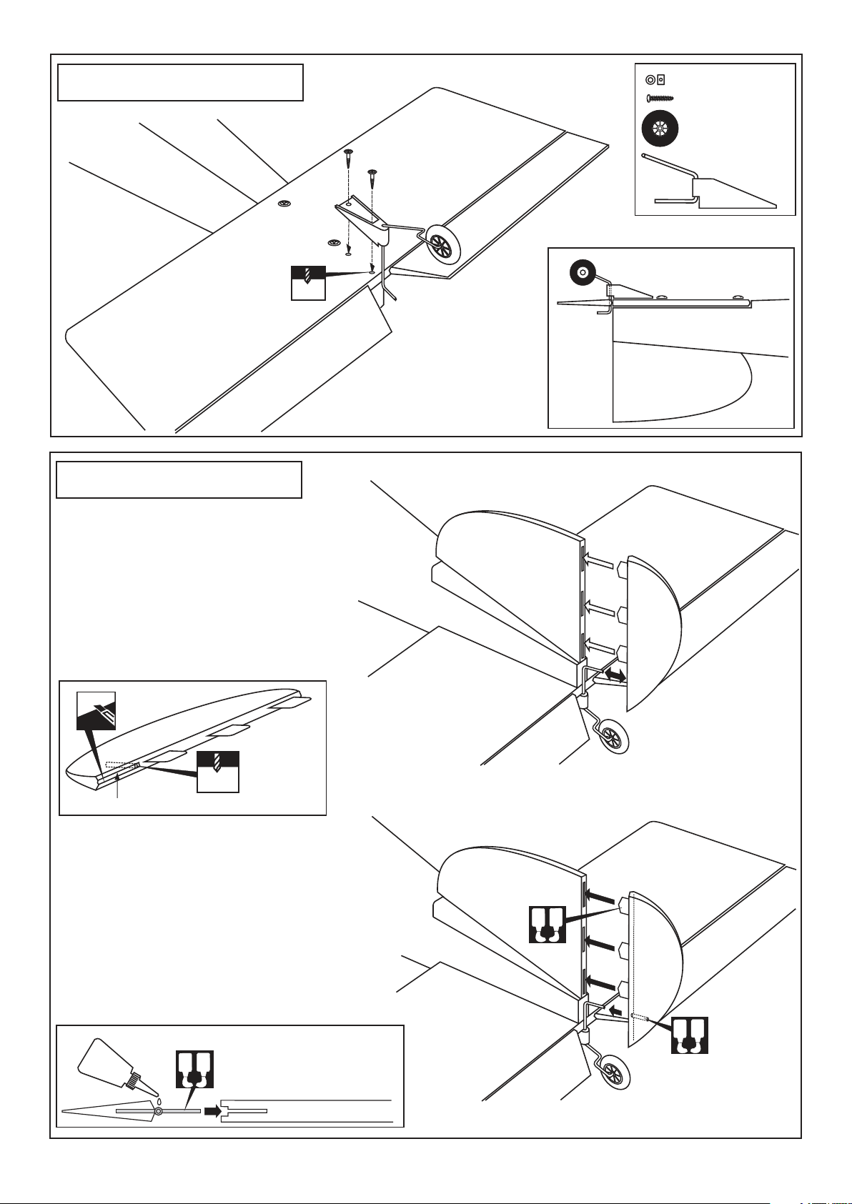
11- Tail wheel
2.2mm collar.....1
Vis 3x12mm......2
Tail wheel..........1
Tail gear mount
...................1
2mm
12- Rudder
Test-fit the hinges of ruder into the slots.
Using a pencil, mark the rudder where the tail
wheel gear meet the rudder.
Cut 1-3/16” (30mm) long slots along the hinge
line in the leading edge of the rudder.
Drill a 3/32”(2.5mm) diameter hole in tail wheel
gear mounting slot, marking sure that you drill
the hole perpendicular to the leading edge of
the rudder.
FUSELAGE
BOTTOM-VIEW
BOTTOM
FUSELAGE
VERTICAL FIN
2.5mm
Tail wheel gear mounting slot
Without using glue yet, push the rudder and its
hinges into the hinge slots in the trailing edge
of the vertical stabilizer, marking sure that the
tail wheel gear is firmly seated in the slot in the
rudder. There should be a minimal hinge gap
and the end of the rudder should not rub against
the vertical stabilizer.
When satisfied with the fit and alignment, hinge
the rudder to the vertical stabilizer, using 5 minute epoxy. Make sure to apply a thin layer of
epoxy to the right and left of both hinges and to
the inside the tail wheel gear mounting slot.
Petroleum jelly
A
B
Apply 5 min. Epoxy both the
right and left.
VERTICAL STAB.
A
B
A
B
Page 8
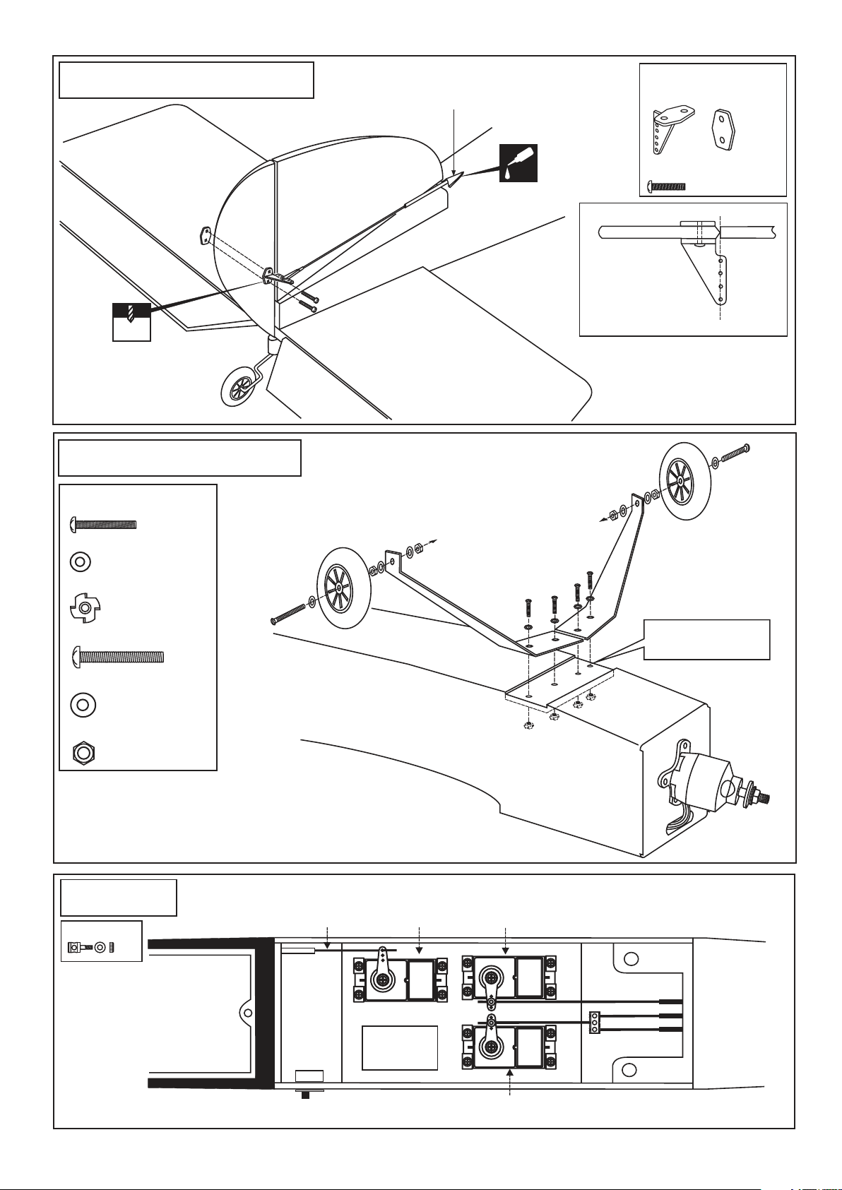
13- Rudder control horn
ABS push-rod exit guider
Plastic control horn
and back plate
.....1
2mm
14- Main landing gear
3x15mm screw
............4
3mm Washer
.....................4
3mm Blind-nut
.....................4
CA
2x12mm screw
...........2
Rudder
4x40mm screw
4mm Washer
.......................6
4mm Nut
......................4
15-Servo
Connector
...2
......2
Fuel tank
area
IN CASE OF GLOW ENGINE
Throttle rod
Throttle servo
All holes pre-drilled
at factory
Rudder servo
Rudder rod
Elevator rod
Switch
Elevator servo
FUSELAGE - TOP VIEW
Page 9
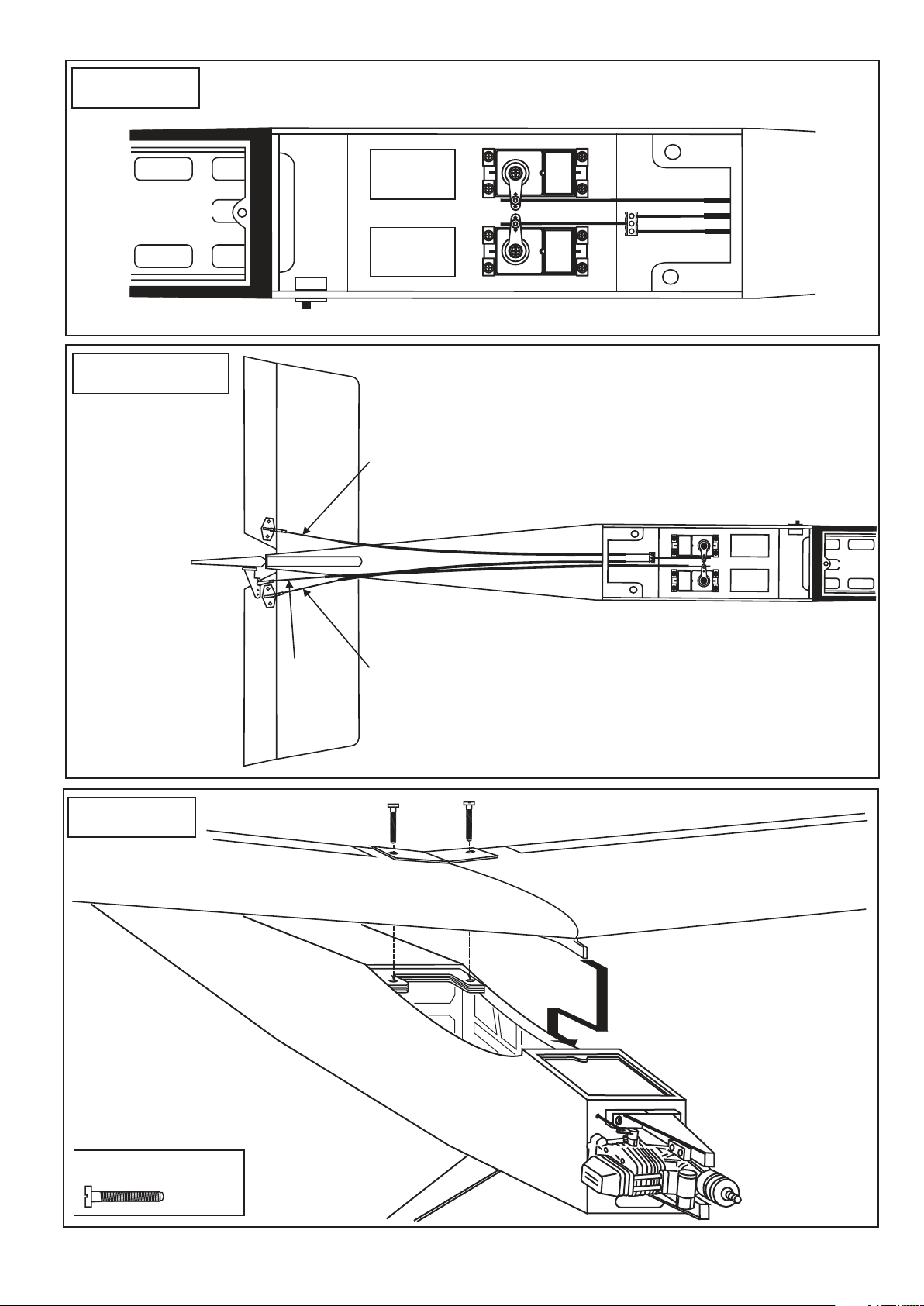
16-Servo
Li-po Battery
area
17- Linkages
IN CASE OF BRUSLESS MOTOR
Rudder servo
Rudder rod
Elevator rod
Switch
Elevator servo
FUSELAGE - TOP VIEW
Elevator push-rod
18- Wing
Rudder
push-rod
Elevator push-rod
Nylon Wing bolt
..........2
Page 10
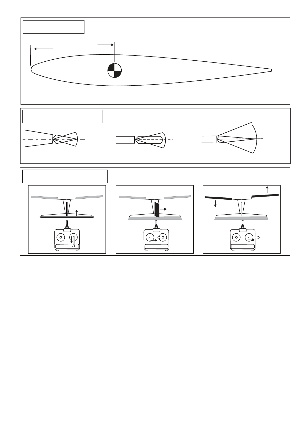
19- Balance
3-33/64” ~ 3-19/32”
89 ~ 91mm
The recommended C.G (Center of Gravity) location for the Stick is 89 ~ 91mm
Adjust the location of the battery pack as required to achieve this C.G location.
If necessary , add weight to either the tail or nose until the correct balance is achieve.
CG
WARNING ! Securely install the receiver and power pack, ensuring they will not come loose or rattle
during flight. Never fly before checking the Cg’s required position.
20-Control Surface
25/64”(10mm)
25/64”(10mm)
AILERON STROKE
21-Pre-Flight check
ELEVATOR
IMPORTANT:
Please do not clean your model with strong solvent or pure alcohol, only use liquid soap with
water or use class cleaner to clean on surface of your model to keep the colour not fade.
25/64”(10mm)
25/64”(10mm)
ELEVATOR STROKE
RUDDER
51/64”(20mm)
51/64”(20mm)
RUDDER STROKE
AILERON
RANGE TEST YOUR RADIO
Turn on the radio in your plane. With your plane on the ground, you should be able to walk 30 paces away
from your plane and still have complete control of all functions. If not, do NOT attempt to fly.
Be sure that your batteries are fully charged per the instructions included with your radio.
BEFORE FLYING
1-Fully extend the transmitter antenna.
2-Switch ON the transmitter.
3-Switch ON the receiver.
4-By moving the throttle control stick, ensure the carburetor opens and closes without effort.
FLYING
1-Take-off your airplane INTO THE WIND.
2-Do not fly your airplane above people standing around.
AFTER FLYING
1-Always land your airplane INTO THE WIND.
2-Switch OFF the receiver.
3-Switch OFF the transmitter.
 Loading...