

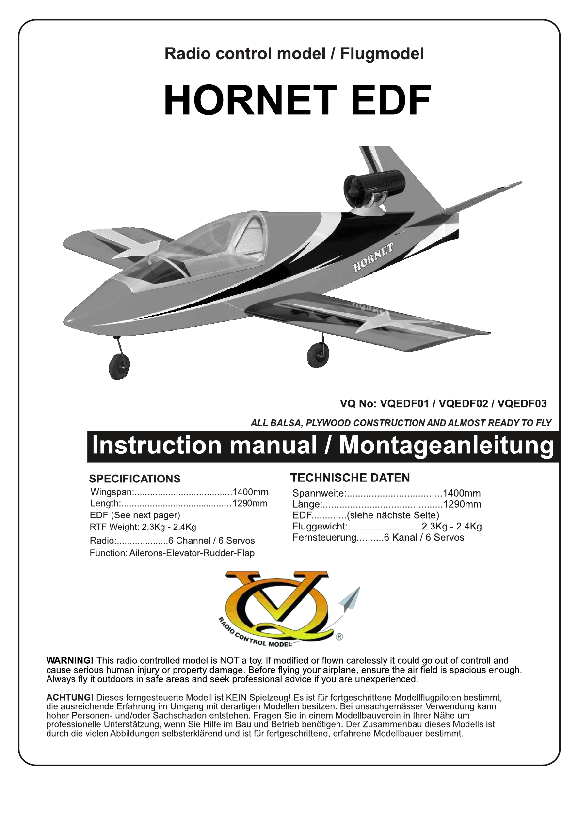
Page 1
Page 2
Instruction manual
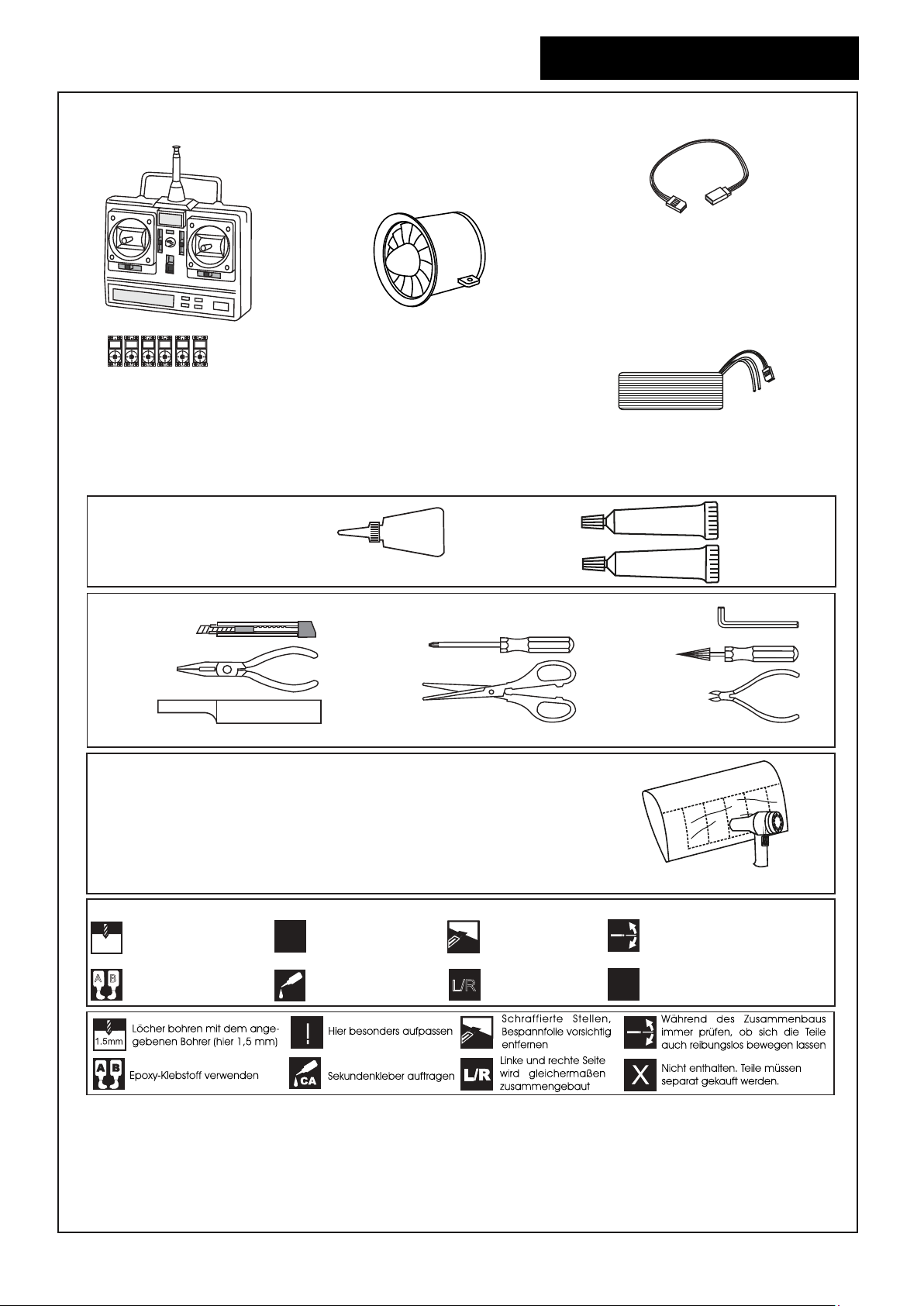
REQUIRED FOR OPERATION (Purchase separately)
EDF 70mm - 2750Kw
Mini Servo
Minimum 6 channels radio
7 Channels with option E-retract
Elevator : 1 mini servo
Aileron: 2 mini servo
Flaps: 2 mini servo
Nose gear: 1 mini servo
Hornet EDF
Extension cord for aileron servos: 50cm(x2)
Extension cord for flap servos: 50cm(x4)
Extension cord for retract servos: 30cm(x2)
Extension cord for Rx battery pack: 20cm(x1)
14.8v - 4500mAh LiPo battery
1
GLUE
(Purchase separately)
EPOXY A
CA
Cyanoacrylate Glue (thin type)
TOLLS REQUIRED
Hobby knife
Needle nose Pliers
Sander
(Purchase separately)
.........................................................
.........................................................
.........................................................
.........................................................
.........................................................
.........................................................
.........................................................
.........................................................
.........................................................
.........................................................
.........................................................
Phillip screw driver
Scissors
Masking tape - Straight Edged Ruler - Pen or pencil - Drill and Assorted Drill Bits
If exposed to direct sunlight and/or heat, wrinkels can appear. Storing the
model in a cool place will let the wrinkles disappear. Otherwise, remove
wrinkles in covering film with a hair dryer, starting with
low temperature. You can fix the corners by using a hot iron.
Bei Sonneneinstrahlung und/oder Wärme kann die Folie erschlaffen bzw. Falten
entstehen. Verwenden Sie ein Warumluftgebläse (Haartrockner) um evtl. Falten aus der Folie
zu bekommen. Die Kanten können Sie mit einem Bügeleisen behandeln. Nicht zuviel Hitze anwenden !
Symbols used throughout this instruction manual, comprise:
Drill holes using the stated
1.5mm
size of drill
(in this case 1.5 mm )
A
B
Use epoxy glue
Take particular care here
!
Apply cyano glue
CA
Hatched-in areas:
remove covering
film carefully
Assemble left and right
L/R
sides the same way.
EPOXY B
Hex Wrench
Awl
Wire Cutters
Check during assembly that these
parts move freely, without binding
Not included.
These parts must be
X
purchased separately
Epoxy Glue
(30 minute type)
Low seting
Read through the manual before you begin, so you will have an overall idea of what to do.
CONVERSION TABLE
1.0mm = 3/64”
1.5mm = 1/16”
2.0mm = 5/64”
2.5mm = 3/32”
3.0mm = 1/8”
4.0mm = 5/32”
5.0mm = 13/64”
6.0mm = 15/64”
10mm = 13/32”
12mm = 15/32”
15mm = 19/32”
20mm = 51/64”
25mm = 1”
30mm = 1-3/16”
45mm = 1-51/64”
Page 3
Instruction manual
Hornet EDF
2
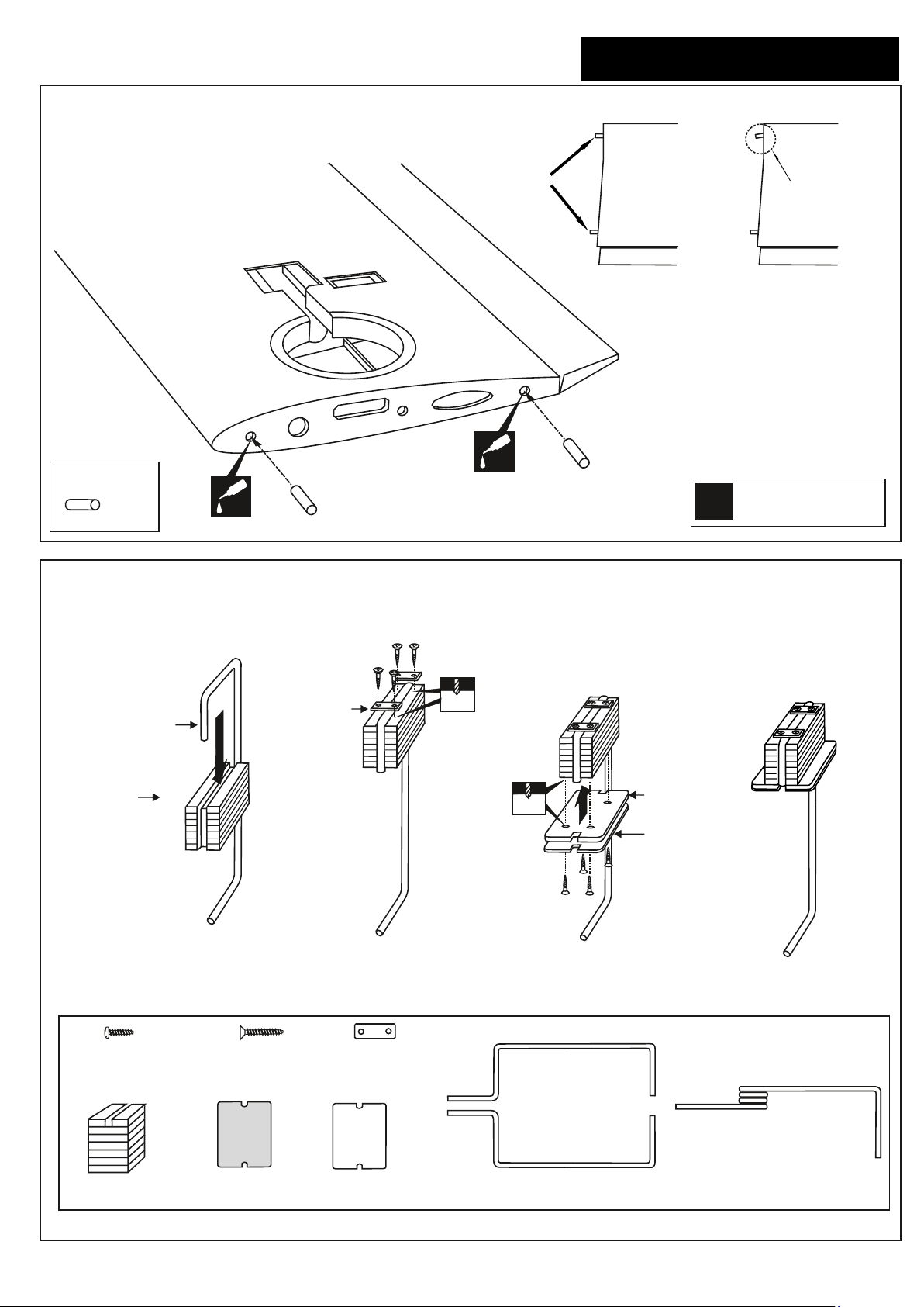
1 Dowel installation
6mm dowel
......4
CA
6mm dowel
wooden dowel
CA
RIGHT
6mm dowel
Half wing panel - top view
WRONG
Assemble left and right
L/R
wings the same way.
2 Fixed gear assemble
Nylon gear
Main landing gear
Gear mount
strap
1
..........8
3x12mm screw
3x20mm screw
......16
.......4
Nylon gear strap
3x20mm
2mm
2
2mm
3x20mm
Ply gear
mount flat
Square
plastic
34
Gear mount x 2
Ply gear mount
plate x 2
Square plastic x 2
Main gear x 2
Nose gear
Page 4
Instruction manual
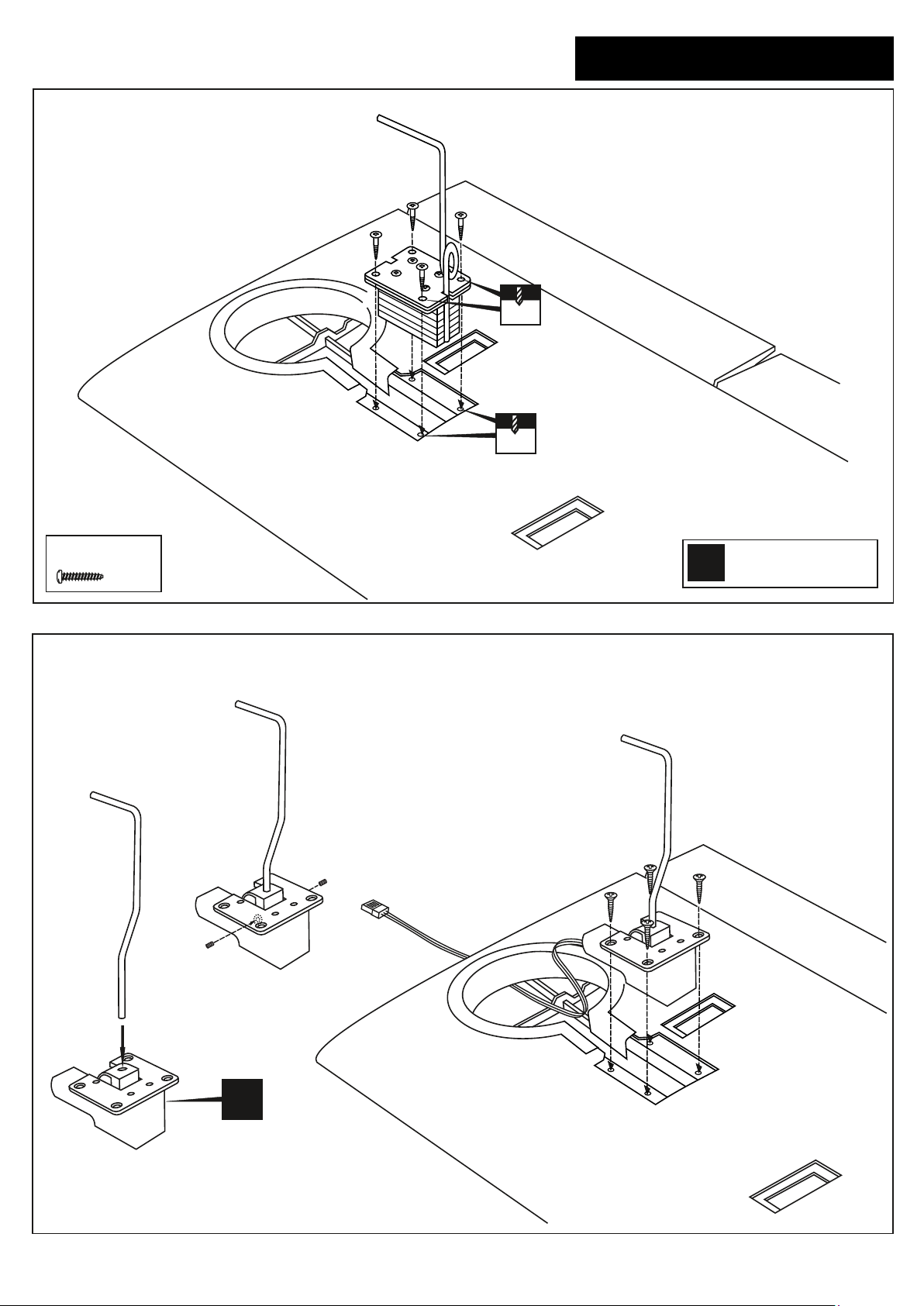
3 Fixed gear installation
2mm
2mm
Hornet EDF
3
3x12mm screw
.......8
4 E-retract installation
Assemble left and right
L/R
wings the same way.
X
Page 5
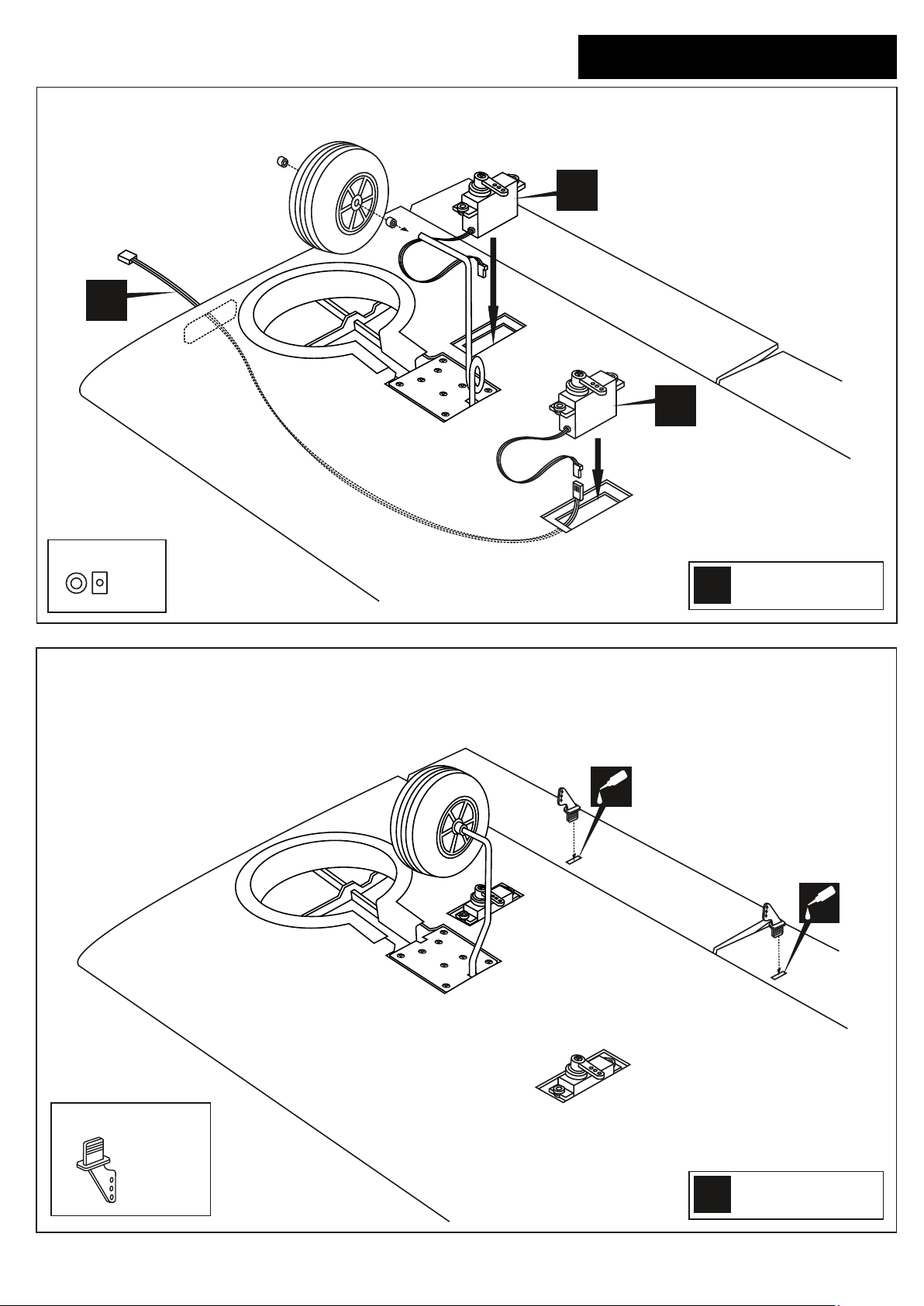
Instruction manual
5 E-retract installation
X
Hornet EDF
X
X
4
4mm collar
.....4
6 Control horn installation
Assemble left and right
L/R
wings the same way.
! Securely glue together. If coming off during fly,
you lose control of your air plane.
CA
CA
Plastic control horn
......2
Assemble left and right
L/R
wings the same way.
Page 6
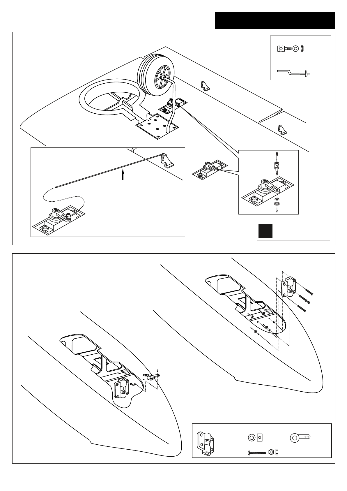
Instruction manual
Hornet EDF
5
7 Servos and linkages
Flap / Aileron pushrod
Connector
............4
Flap/Aileron push rod
(1.2x150mm)
......4
8 Nose gear mount
Insert the nose gear pushrod into the
fuselage with the “Z” bend in front.
Insert the “Z” bend into the hole on the
nose gear control horn.
Step 8B
Assemble left and right
L/R
wings the same way.
Step 8A
Nose gear mount
.....1
Attach the plastic nose gear mount
to the plywood nose gear plate using
four 3x20mm screws and nuts.
4mm collar
.....4
3x20mm
Nose gear arm
.....1
Page 7
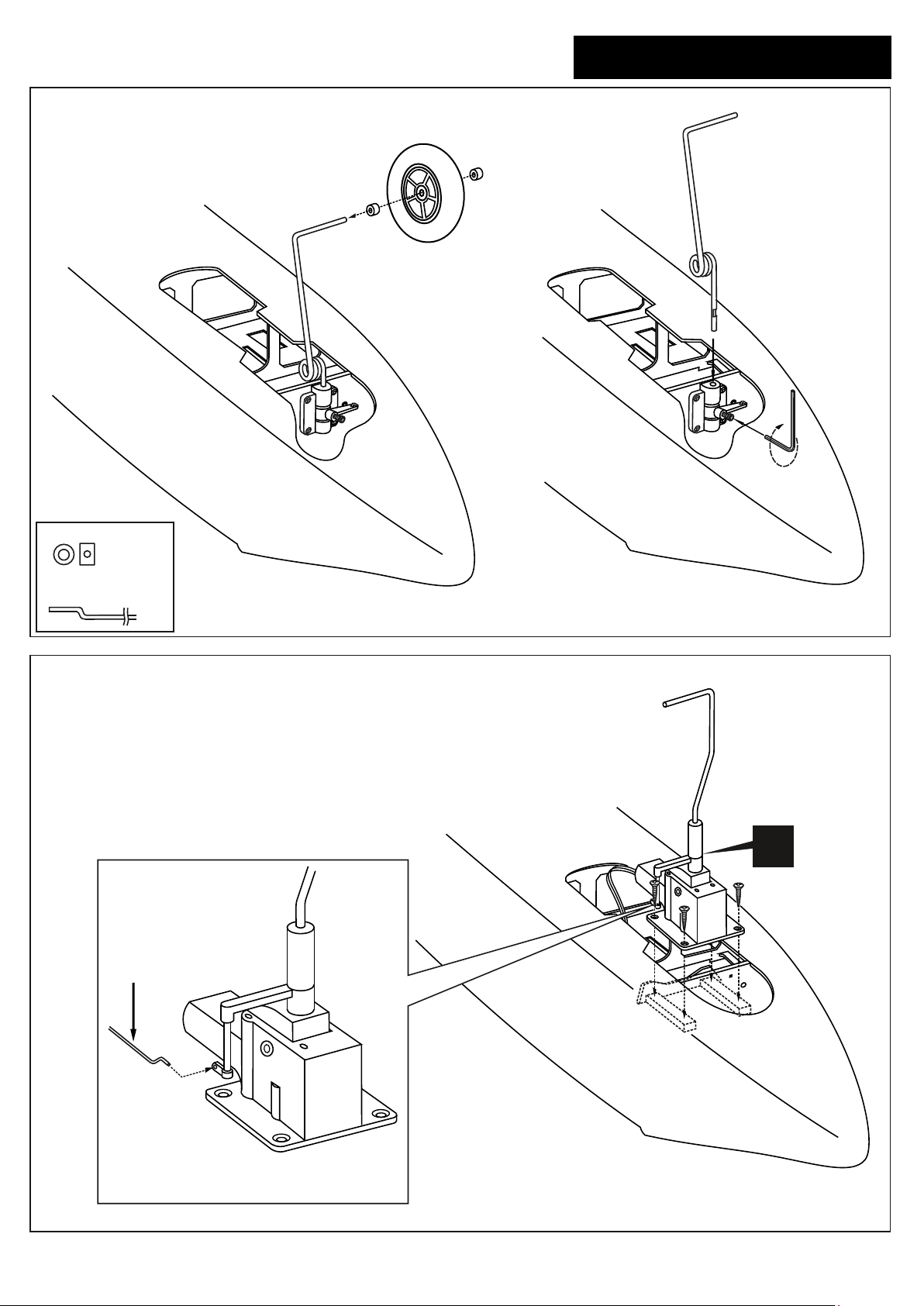
Instruction manual
9 Nose gear installation
Step 9B
Hornet EDF
Step 9A
6
Wrench
4mm collar
.....2
Nose gear push rod
(1.2x550mm)
.....1
10 E-retract (Nose gear) installation
Nose retract pushrod
X
Insert the “Z” bend into the hole on the
nose gear control horn.
Page 8
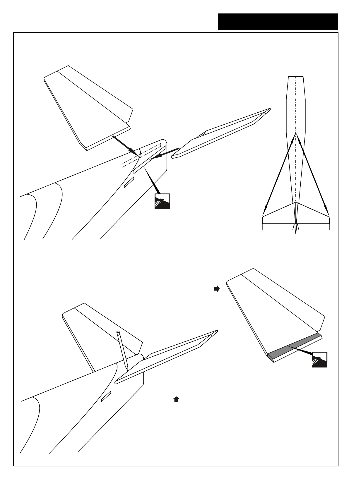
Instruction manual
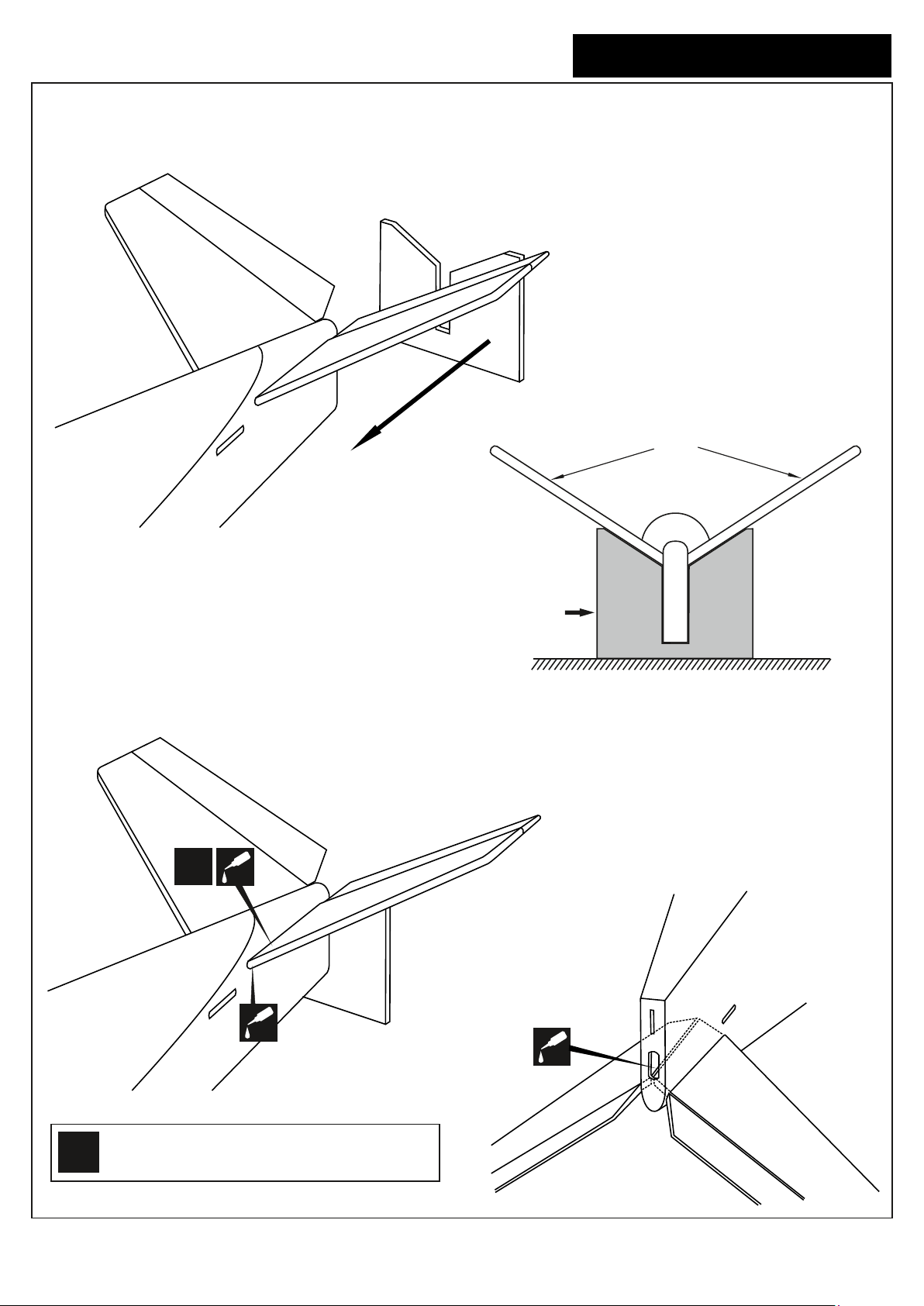
11 Stabilizer installation
Hornet EDF
Push the horizontal stabilizer into the slot on the fuselage
as show. Check the alignment of the horizontal stabilizer
by measuring from a fixed point along the center line of
the fuselage to the leading edge on each side of the
horizontal stabilizer. The distance must be equal on both
sides . If not, adjust the stabilizer until the measurements
are the same (see picture below: A=A’).
Step 11A
7
Cut away only
the covering
both side
Remove the horizontal stabilizer from the fuselage. Using a sharp hobby knife,
carefully cut away the covering inside the lines which were marked above.
Be cautious not to cut into the wood this will weaken the structure.
Step 11B
A
A’
A=A’
Step 11C
When you are satisfied with the alignment, use
a pencil to trace around the top and bottom of
the stabilizer where it meets the fuselage.
Cut away only
the covering
both side
Page 9
Instruction manual
12 Stabilizer installation continued
Step 12A
Carton template
Hornet EDF
“V” Tail
8
L/R
CA
CA
Apply CA glue
both sides.
(thin CA)
Carton template
FUSELAGE AND “V”TAIL - REAR-VIEW
Step 12B
Top-view
Step 12C
Glue the underside of the
tail through the hole
CA
! Securely glue together. If coming off during fly,
!
you lose control of your air plane.
Bottom-view
Page 10
Instruction manual
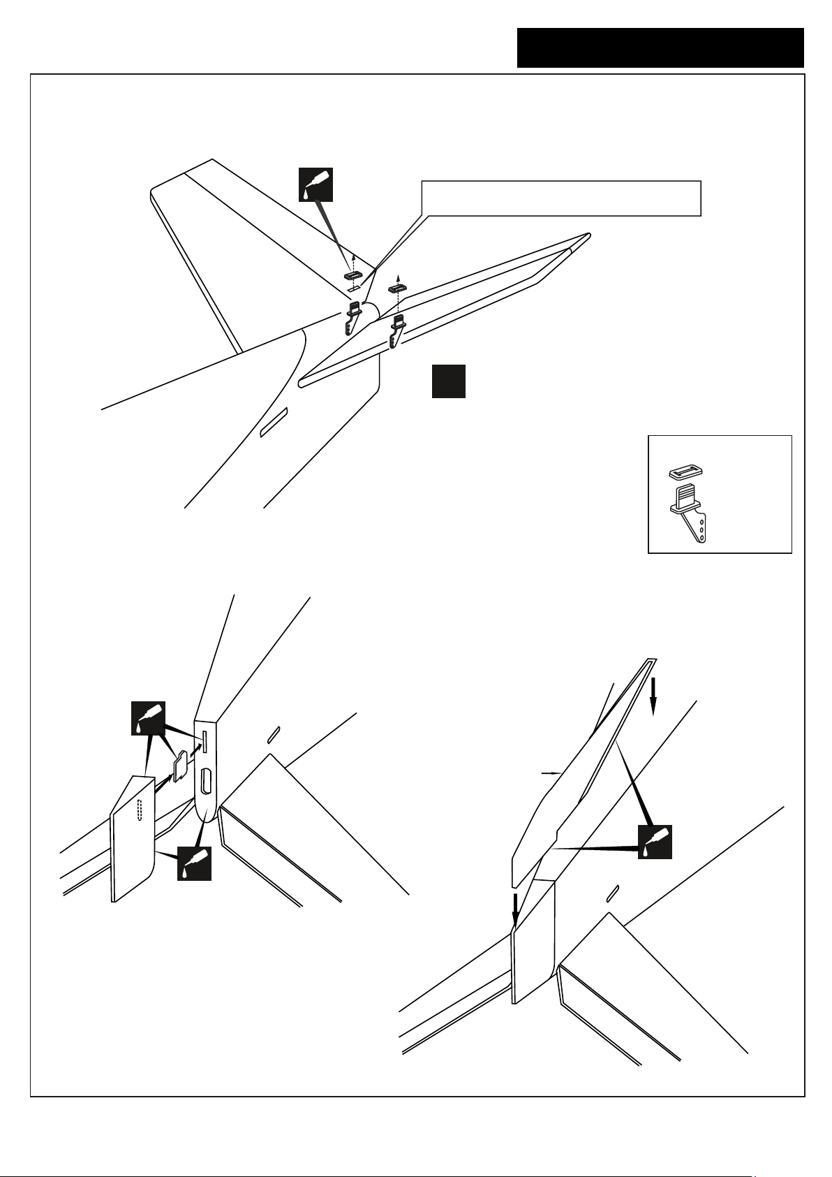
13 Control horn installation
Hornet EDF
9
Step 13A
Top-view
CA
Note: The rectangle hole on the elevator
is pre-cut at factory. Cut away only the covering
Note: Flow the one end (with the “Z”) of the elevator
push rod (1.2x950mm) into the elevator control horn
!
before attach the Stabilizer to the fuselage.
Plastic control horn
......2 set
Step 13B
CA
Bottom-view
CA
Plastic bottom
fillet
Bottom-view
Step 13C
CA
Page 11
Instruction manual
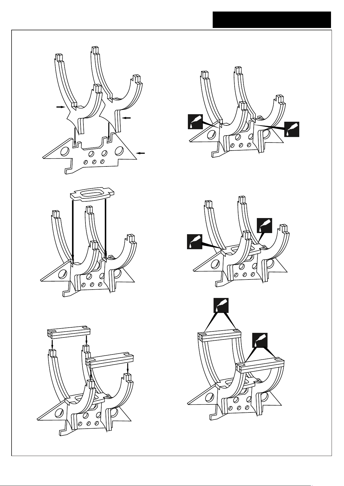
14 Ducted fan mount assemble
Hornet EDF
10
Bm2x2pcs
Step 13A
Bm3x2pcs
CA
BM1
BM4
Step 13B
Step 13CStep 13D
CA
Apply CA glue
both sides.
(thin CA)
BM5X2PCS
CA
CA
CA
Step 13EStep 13F
BM5X2PCS
CA
Page 12
Instruction manual
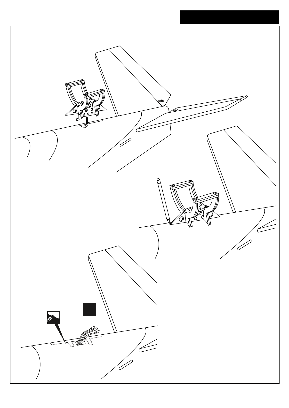
15 Ducted fan mount installation
Step 14A
Slide the Fan mount into the slot on
the top of the fuselage as shown.
Hornet EDF
11
Step 14C
Cut away only
the covering
Using a pencil, trace around the fan mount
where it meets the fuselage.
Remove the fan mount from the fuselage.
X
Electric cord
for EDF
Step 14B
Using a sharp hobby knife, carefully cut away
the covering inside the lines which were marked
above. Be cautious not to cut into the wood-this
will weaken the structure.
Note: Insert the Electric cord for EDF into the
fuselage at this time.
Page 13
Instruction manual
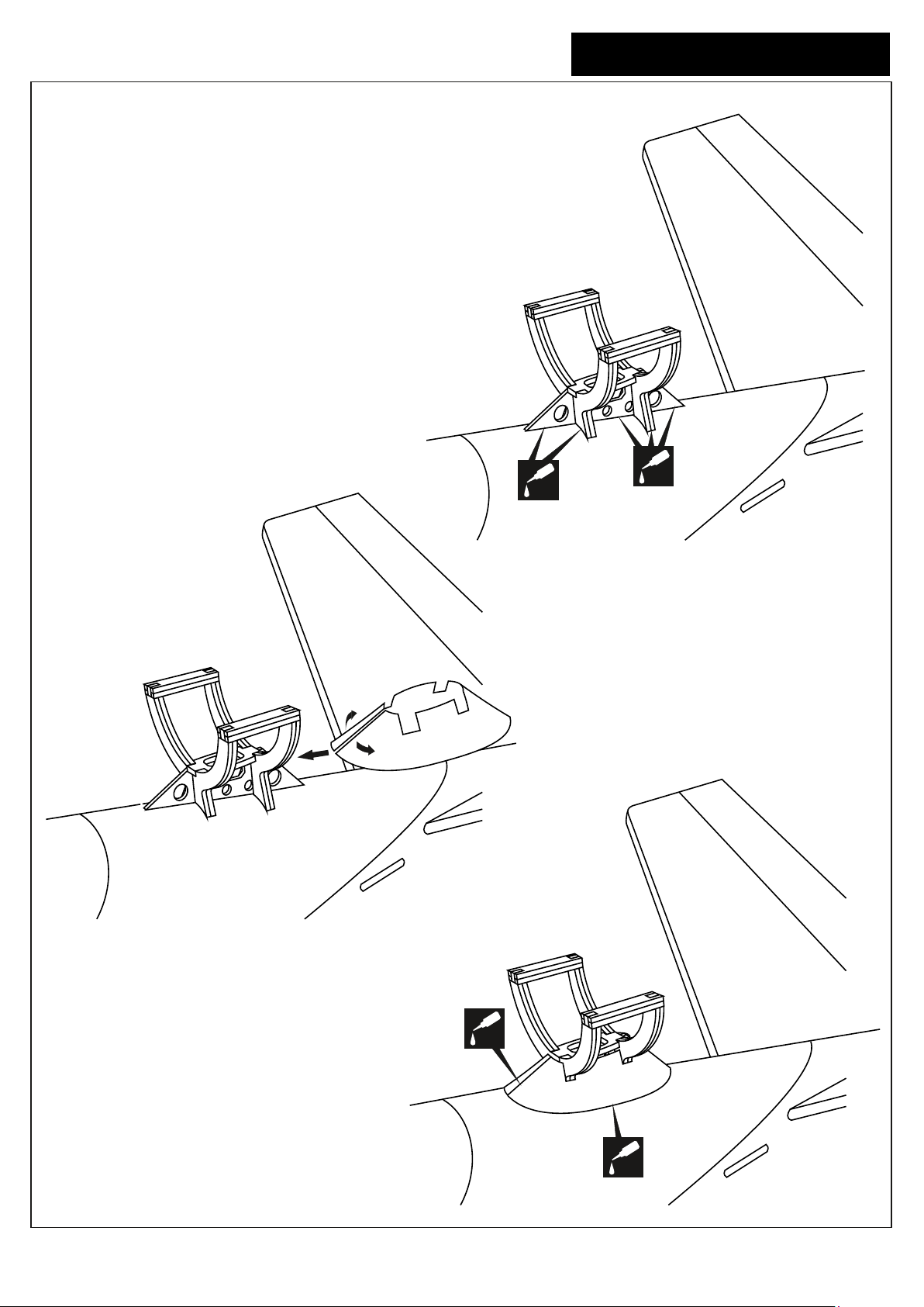
16 Ducted fan mount installation
Hornet EDF
12
Slide the Fan mount into the slot on
the top of the fuselage as shown.
Secure the Fan mount in place using
the thin CA
! Securely glue together. If coming off during fly,
you lose control of your air plane.
Step 15A
CA
CA
Secure the plastic fan mount cover
in place using the thin CA
Slide the plastic fan mount cover in place
Step 15C
CA
CA
Page 14
Instruction manual
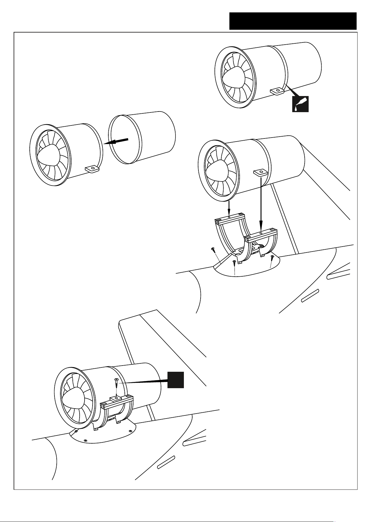
17 Ducted fan installation
Hornet EDF
13
Step 16A
Fiberglass exhaust
2x5mm self tapping screw
CA
Step 16C
Step 16D
X
Page 15
Instruction manual
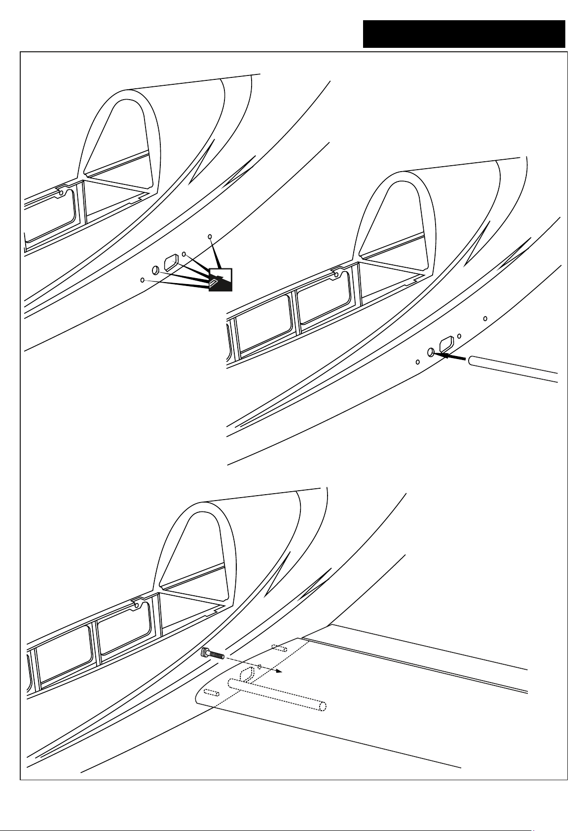
18 Wing installation
Cut away only
the covering
both side
Hornet EDF
14
Pull the aluminum tube through the fuselage
Carefully, push the wing to touch
the fuselage
Secure the wing in place using the
4x20mm plastic bolt.
Page 16
Instruction manual
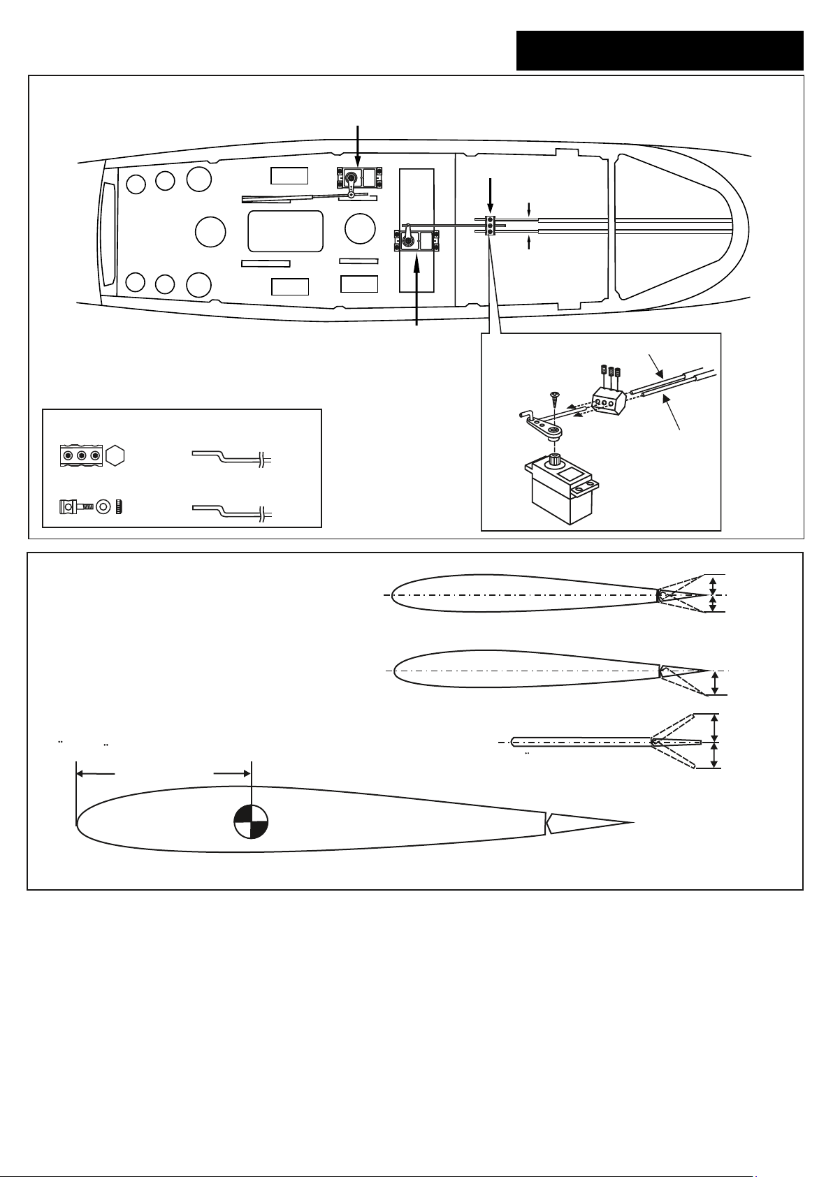
19 Servo and linkages
Nose gear servo
Connector
Elevator pushrod
Elevator pushrod
Hornet EDF
15
Elevator servo
Connector
.........1
Connector
............4
Nose gear push rod
(1.2x550mm)
......1
Elevator push rod
(1.2x950mm)
......2
20- Balance and control surface
Do not try to fly an out-of balance model!
Uberprufen Sie vor dem Flug den Schwerpunkt.
75 ~ 80mm
Elevator pushrod
3mm set Screw
Elevator pushrod
Aileron
Querruderausschlag
Flap
Elevator
Hohenruderausschlag
15mm
15mm
20mm
15mm
15mm
 Loading...