

Page 1
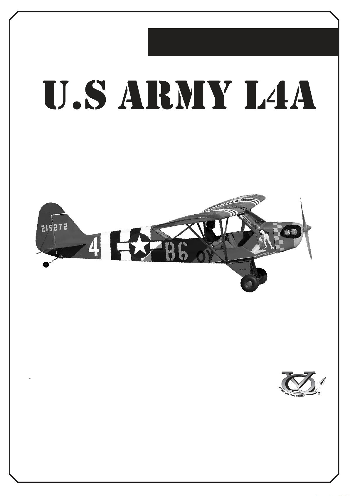
Radio control model
INSTRUCTION MANUAL
R/C Flugmodell
MONTAGEANLEITUNG
GRASSHOPPER
ARF BY
TECHNISCHE DATEN
Spannweite 2710mm
Lange 1720mm
Elektroantrieb (siehe nächste Seite)
Verbrennerantrieb 26-30cc 2-T
Fernsteuerung 6 Kanal / 8 Servos
WARNING! This radio controlled model is NOT a toy. If modified or flown carelessly it could go out of controll and
cause serious human injury or property damage. Before flying your airplane, ensure the air field is spacious enough.
Always fly it outdoors in safe areas and seek professional advice if you are unexperienced.
ACHTUNG! Dieses ferngesteuerte Modell ist KEIN Spielzeug! Es ist für fortgeschrittene Modellflugpiloten bestimmt,
die ausreichende Erfahrung im Umgang mit derartigen Modellen besitzen Bei unsachgemäßer Verwendung kann
hoher Personen- und/oder Sachschaden entstehen. Fragen Sie in einem Modellbauverein in Ihrer Nähe um
professionelle Unterstützung, wenn Sie Hilfe im Bau und Betrieb benötigen. Der Zusammenbau dieses Modells ist
durch die vielen Abbildungen selbsterklärend und ist für fortgeschrittene, erfahrene Modellbauer bestimmt.
SPECIFICATIONS
Wingspan 106.6in.
Length 67.7 in.
Electric Motor (See next page)
Glow Engine 26-30cc two stroke
Radio 6 Channel / 8 Servos
Page 2
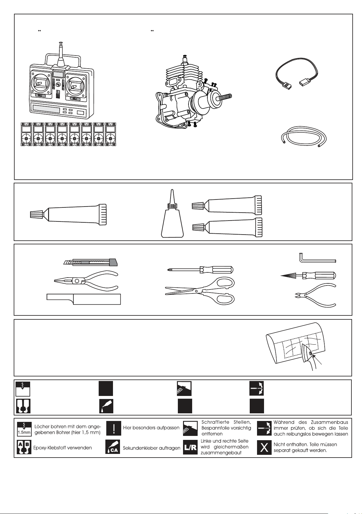
REQUIRED FOR OPERATION (Purchase separately)
BENOTIGTE KOMPONENTEN FUR DEN ABFLUG (Nicht enthalten)
Extension for aileron
servo, Flap servo.
Gas Engine: 26 ~ 30cc
Minimum 6 channel radio
for airplane with 8 servos
.Motor control x1 .Aileron x2
.Elevator x2 .Rudder x1 .Flap x 2
GLUE
TOLLS REQUIRED
Hobby knife
(Purchase separately)
SILICON
Silicon sealer
Cyanoacrylate
Glue
Klebstoff
(Purchase separately)
CA
Phillip screw driver
Needle nose Pliers
Scissors
Sander
.........................................................
.........................................................
.........................................................
.........................................................
.........................................................
.........................................................
.........................................................
.........................................................
.........................................................
.........................................................
.........................................................
Masking tape - Straight Edged Ruler - Pen or pencil - Drill and Assorted Drill Bits
If exposed to direct sunlight and/or heat, wrinkels can appear. Storing the
model in a cool place will let the wrinkles disappear. Otherwise, remove
wrinkles in covering film with a hair dryer, starting with
low temperature. You can fix the corners by using a hot iron.
EPOXY A
EPOXY B
Nylon tube
Epoxy Glue (5 minute type)
Epoxy-Klebstoff (5min-Typ)
Epoxy Glue (30 minute type)
Epoxy-Klebstoff (30min-Typ)
Hex Wrench
Awl
Wire Cutters
Bei Sonneneinstrahlung und/oder Wärme kann die Folie erschlaffen bzw. Falten
entstehen. Verwenden Sie ein Warumluftgebläse (Haartrockner) um evtl. Falten aus der Folie
zu bekommen. Die Kanten können Sie mit einem Bügeleisen behandeln. Nicht zuviel Hitze anwenden !
Drill holes using the stated
size of drill
1.5mm
(in this case 1.5 mm Ø)
A
B
Use epoxy glue
Take particular care here
!
Apply cyano glue
CA
Hatched-in areas:
remove covering
film carefully
Assemble left and right
L/R
sides the same way.
Check during assembly that these
parts move freely, without binding
Not included.
These parts must be
X
purchased separately
Read through the manual before you begin, so you will have an overall idea of what to do.
CONVERSION TABLE
1.0mm = 3/64”
1.5mm = 1/16”
2.0mm = 5/64”
2.5mm = 3/32”
3.0mm = 1/8”
4.0mm = 5/32”
5.0mm = 13/64”
6.0mm = 15/64”
10mm = 13/32”
12mm = 15/32”
15mm = 19/32”
20mm = 51/64”
25mm = 1”
30mm = 1-3/16”
45mm = 1-51/64”
Low setting
Page 3
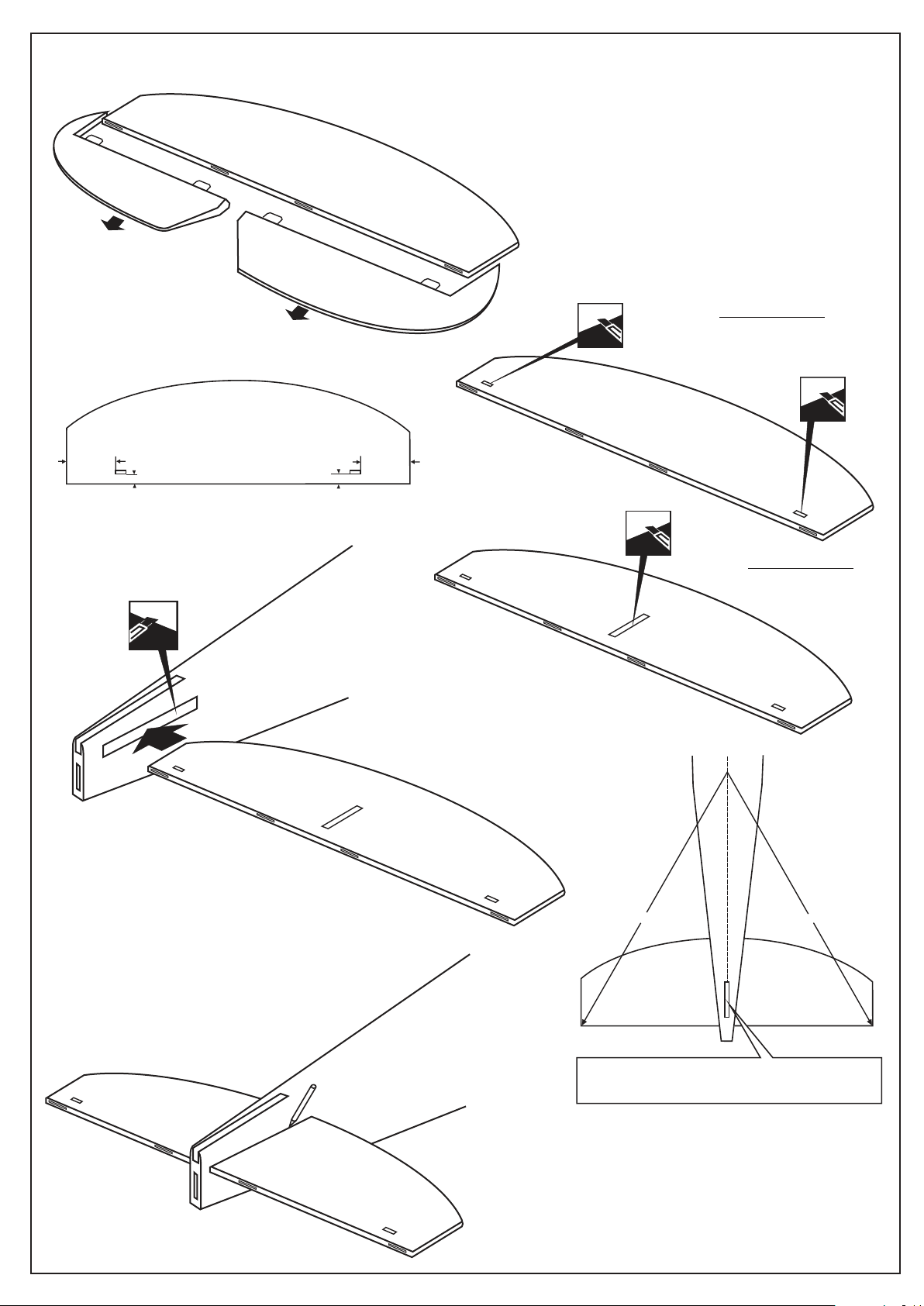
HORIZONTAL STABILIZER - VERTICAL STABILIZER
1
Full the elevator out of the
horizontal stabilizer.
HORIZONTAL STABILIZER
TOP VIEW / Draufsicht
35mm
19mm
Cut away only the
covering both side
19mm
35mm
TOP VIEW / Draufsicht
Cut two slots (only the covering) on the
top and along the trailing edge of the
horizontal stabilizer.
2
Cut away only the covering on the
top and bottom
3
4
Trial fit the horizontal stabilizer in place . Check the alignment
of the horizontal stabilizer. When you are satisfied with the
alignment, use a pencil to trace around the top and bottom
of the stabilizer where it meets the fuselage.
5
A A’
A=A’
The slot on the horizontal stabilizer and the slot
on the fuselage must be coincidental.
Page 4
6
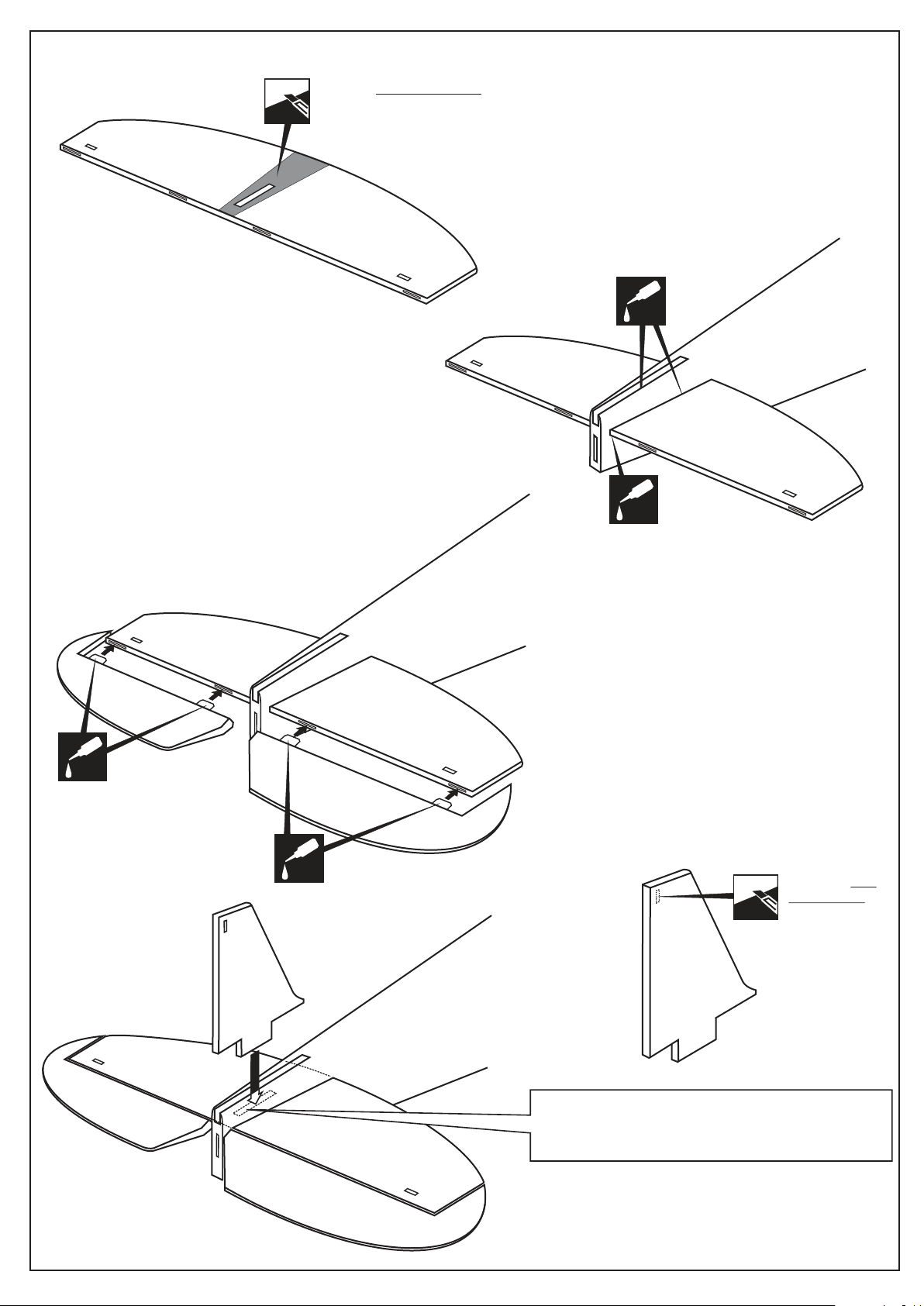
Cut away only the covering
on the top and bottom
Pull the horizontal stabilizer through the other side
of the fuselage and repeat the previous procedures
to glue the second torque rod wire into the horizontal
stabilizer.
Realign the horizontal stabilizer, then glue the
horizontal stabilizer into the fuselage, using a
generous amount of thin CA. Apply thin CA to each
of the four joints and use a generous amount to
ensure to strong bond.
Remove the horizontal stabilizer from the fuselage.
Using the sharp hobby knife, carefully cut away the
covering inside the lines which were marked above.
CA
8
CA
Thin CA
glue
CA
7
CA
The elevator hinges are pre-glue into the
elevator halves. Working with one elevator half
for now, apply a thin layer of petroleum jelly to
only the pivot point of the two hinges.
Without using glue yet, push the elevator half
and its hinges into the hinge slots in the trailing
edge of the horizontal stabilizer. There should
be a minimal hinge gap and the end of the
elevator half should not rub against the
horizontal stabilizer.
When satisfied with the fit and alignment, hinge
the elevator half to the horizontal stabilizer,
using thick CA glue. Make sure to apply a thin
layer of CA glue to the top and bottom of both
hinges. Repeat the previous procedures to
hinge the second elevator half to the other side
of the horizontal stabilizer.
Cut away only
the covering
both sides.
10
9
NOTE: You may need to open up the slots of the
horizontal stabilizer so that the vertical stabilizer
is not too difficult to push in.
Page 5
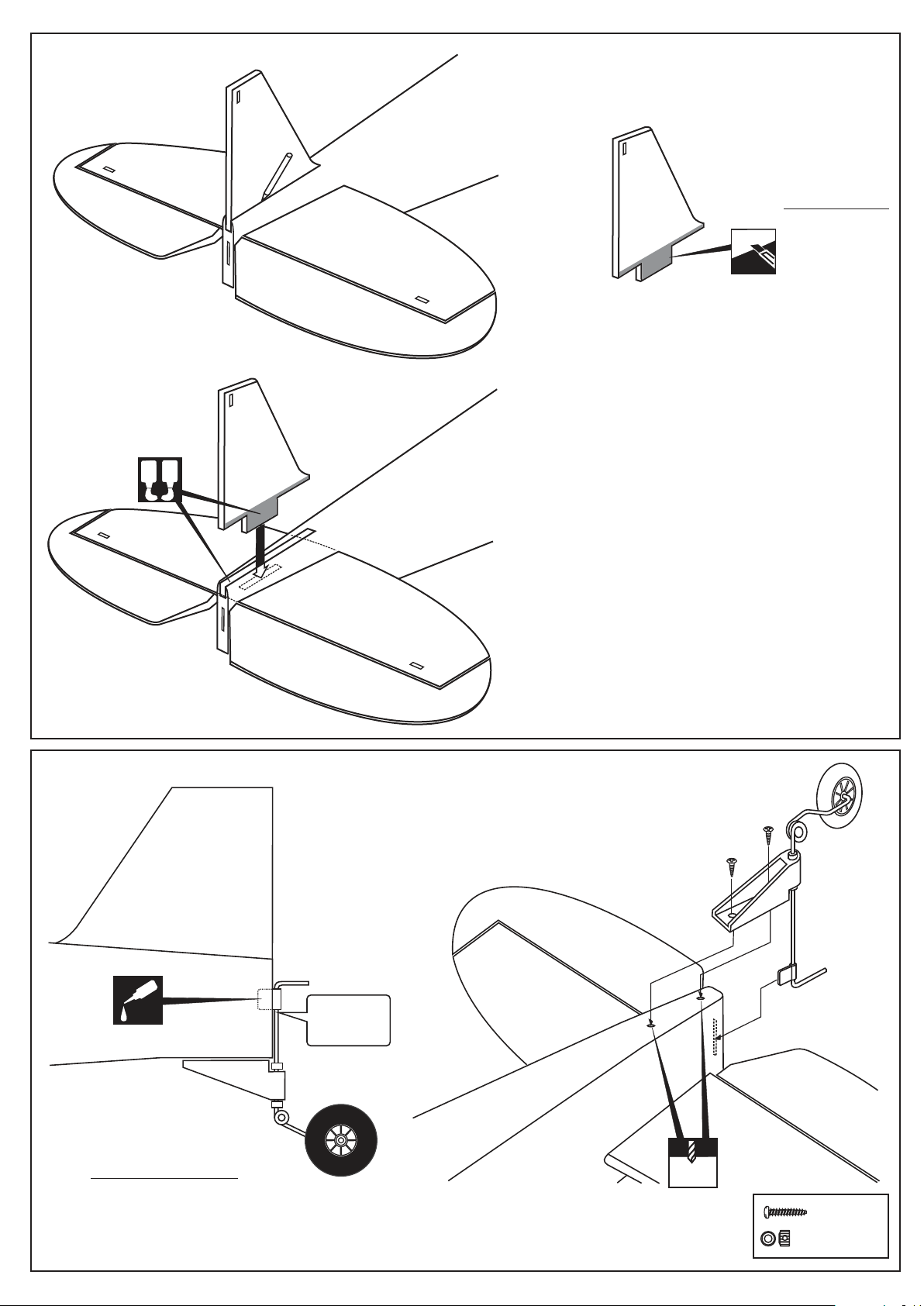
11
5 min.
Epoxy
A
B
Trial fit the vertical stabilizer in place . Check the alignment
of the vertical stabilizer. When you are satisfied with the
alignment, use a pencil to trace around the right and left
of the stabilizer where it meets the fuselage.
12
Cut away only the covering
on the left and right side.
Remove the vertical stabilizer from the fuselage.
Using the sharp hobby knife, carefully cut away the
covering inside the lines which were marked above.
Realign the vertical stabilizer , ensure that the vertical
stabilizer is perpendicular to the horizontal stabilizer.
Then glue the vertical stabilizer into the fuselage, using
a generous amount of 5 min. Epoxy. Apply thin epoxy
to each of the two joints and the entire bottom edge of
the vertical stabilizer, use a generous amount to
ensure to strong bond.
13
TAIL WHEEL
VERTICAL STABILIZER
CA
FUSELAGE - SIDE VIEW
3x12mm screw
Petroleum
jelly
2mm
3x12.......2
....................2
Page 6
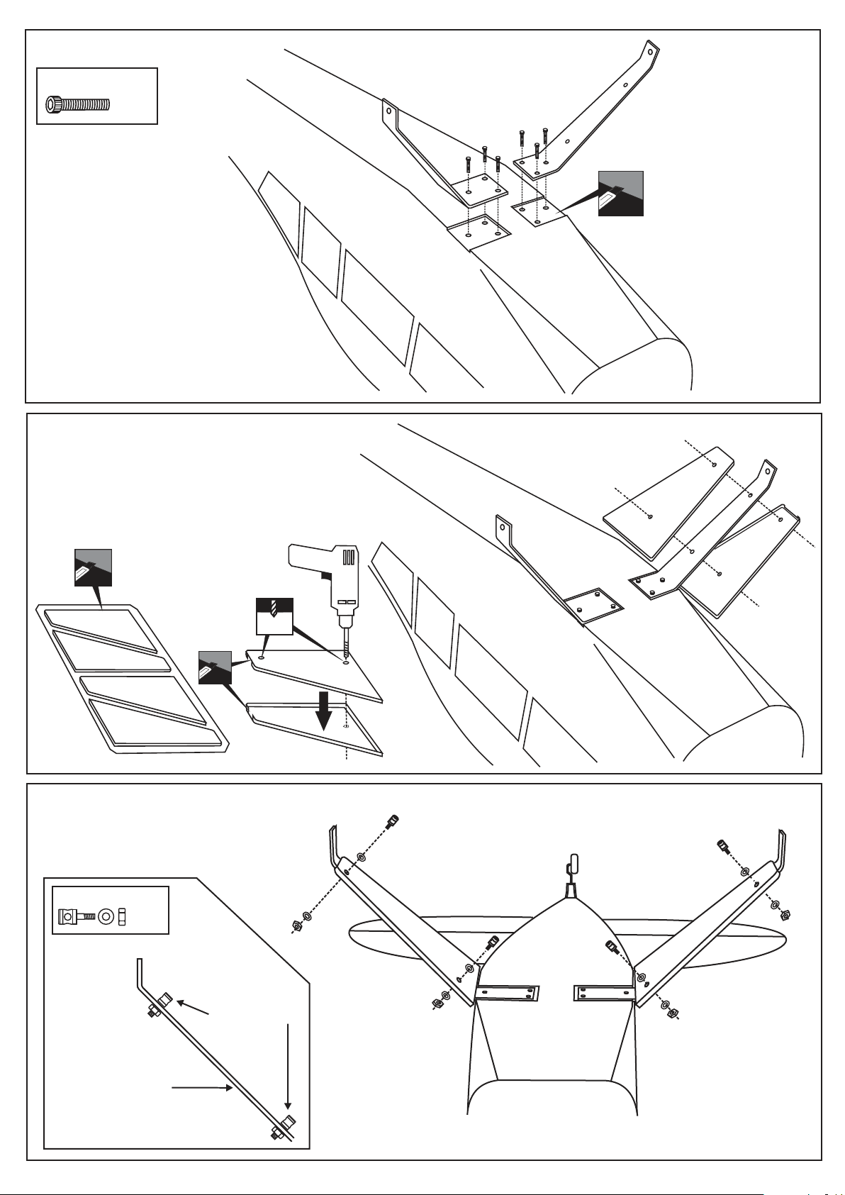
MAIN LANDING GEAR
4X20mm screw
.....6
* WARNING: When removing any covering
from the airframe, please ensure that you
secure the cut edge with CA or similar cement.
This will ensure the covering remain tight.
BOTTOM - VIEW / Unteransicht
Cut away only the covering
MAIN LANDING GEAR
MAIN LANDING GEAR
BOTTOM - VIEW / Unteransicht
3mm
3mm connector
3mm connector
Connector
......4
Aluminum landing
gear
Hauptfahrwerk
3mm connector
BOTTOM - VIEW / Unteransicht
Page 7
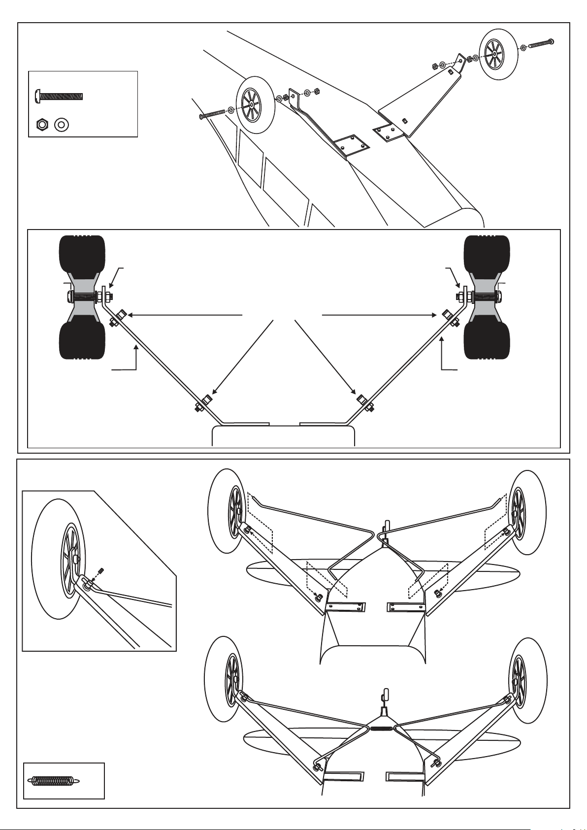
MAIN LANDING GEAR
4X40mm screw
............2
4mm nut-washer
BOTTOM - VIEW / Unteransicht
4mm nut
4x30mm
screw
Aluminum landing
gear
Hauptfahrwerk
MAIN LANDING GEAR
4mm nut
4x30mm
screw
3mm connector
Aluminum landing
gear
Hauptfahrwerk
FUSELAGE
...1
Page 8
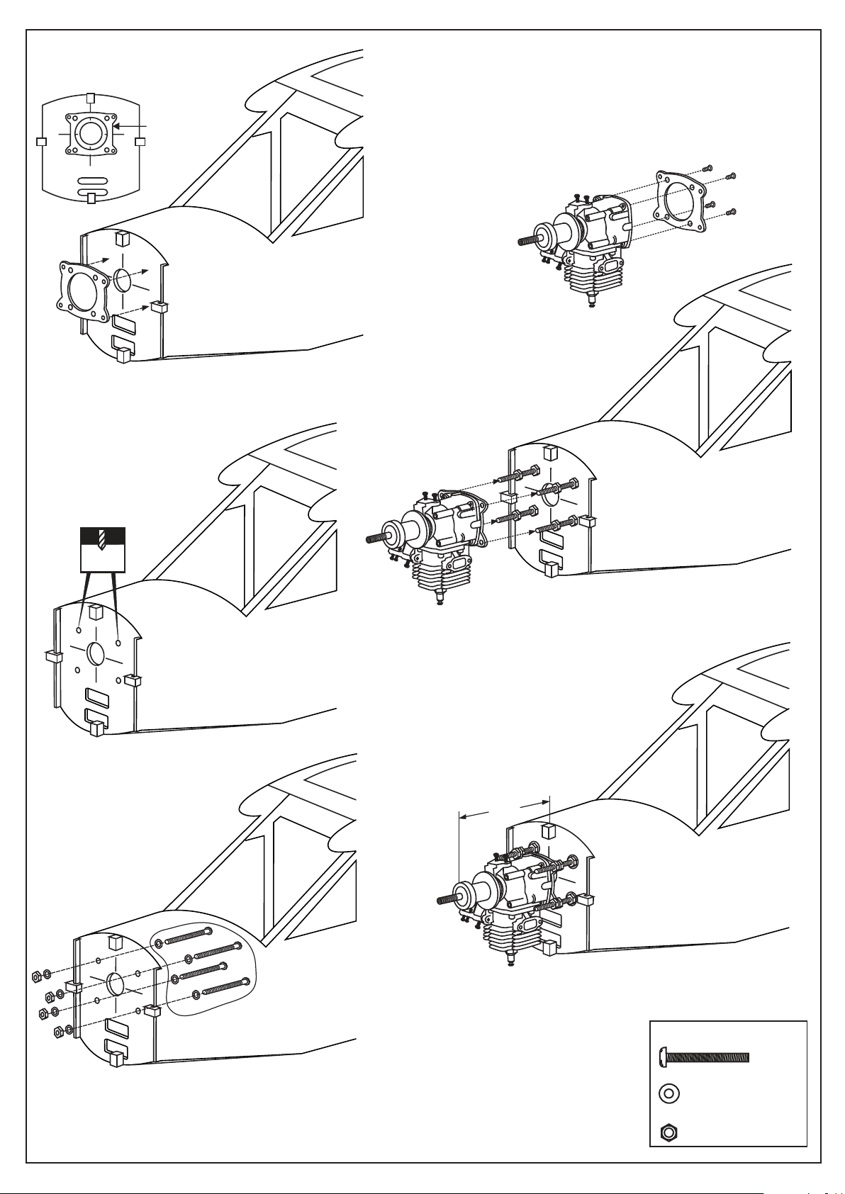
ENGINE
1
Aluminum motor
mounting plate
Using a aluminum motor mounting plate as a template, mark the fire-wall
where the four holes are to be drilled (1).
Remove the aluminum motor mounting plate and drill a 5mm hole
through the plywood at each of the four marks marked (2).
Note: The aluminum motor mounting and screws included with the engine.
4
2
13/64”
5mm
5
B=152-158mm
B
3
6
5X60mm screw
.........4
5mm washer
..................16
5mm nut
..................12
Page 9
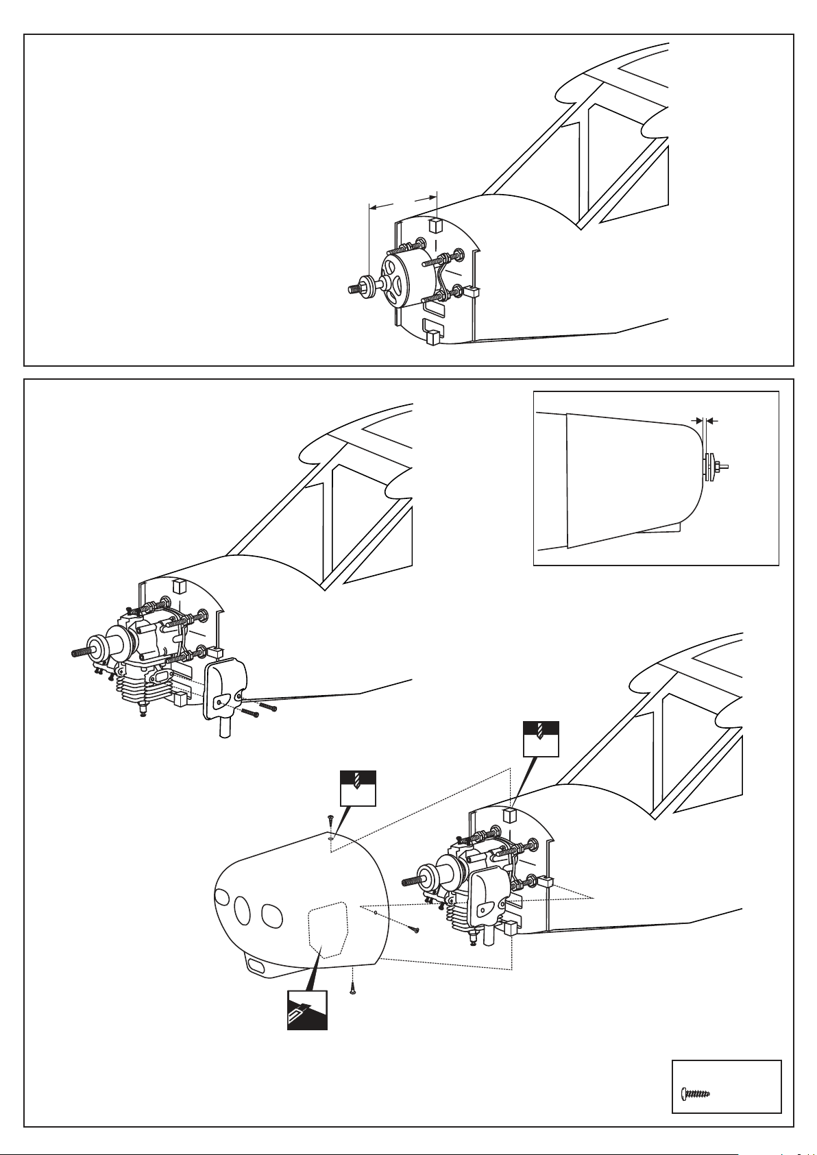
ELECTRIC MOTOR
Using a aluminum motor mounting plate as a template, mark the fire-wall
where the four holes are to be drilled (1).
Remove the aluminum motor mounting plate and
drill a 5mm hole through the plywood at each of the
four marks marked (2).
Note: The aluminum motor mounting and screws
included with the motor.
B=152-158mm
B
COWLING
4 - 6mm
2.mm
Relive the cowl to clear the silencer,
carburetor and plug.
2.mm
23x8mm screw
............4
Page 10
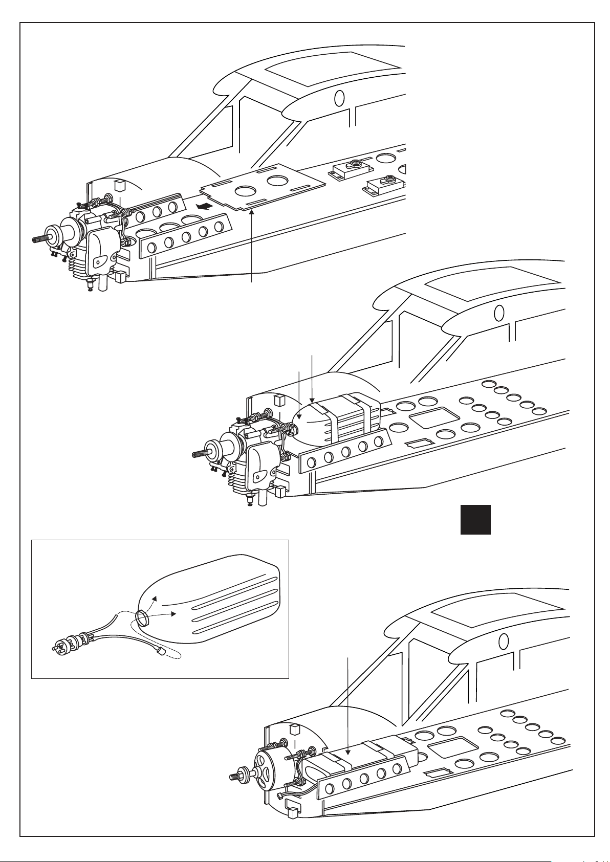
FUEL TANK & LIPO. BATTERY
Fuel tank flat (3mm plywood)
Fuel tank assembly
Fuel tank seat bell
30cc Fuel tank
Tipp
Fuel tank seat bell
X
Akku Kiettband
aus dem PICHLER
Sortiment
Best.Nr. C4739
Li-po battery
Page 11
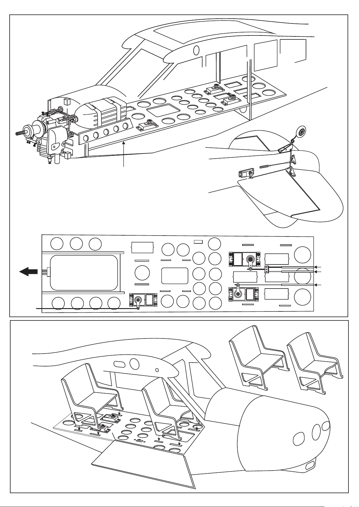
SERVO
Servo tray
IN CASE OF THE ELEVATOR SERVO IN SIDE
OF THE FUSELAGE
FRONT
Throttle
pushrod
FUEL TANK
IN CASE OF THE ELEVATOR SERVO
OUT SIDE OF THE FUSELAGE
SERVO TRAY - TOP VIEW
Servo tray
Throttle servo
Elevator servo
Elevator
pushrod
Rudder
pushrod
Rudder servo
REAR
FRONT
Page 12
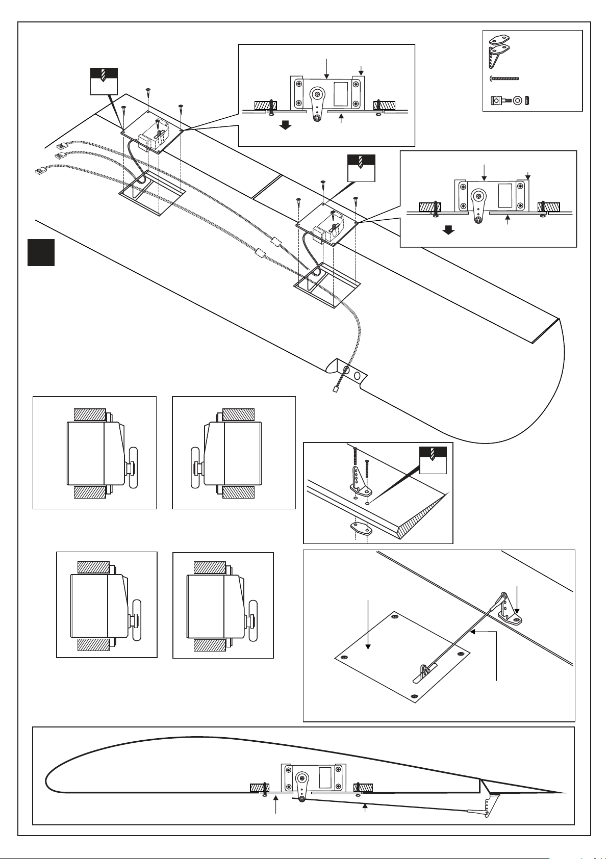
SERVO
1.5mm
2x10mm
screw
Flap servo
Servo mount
Control horn
......................4
2x30mm screw
...................8
Connector
...............4
X
Aileron, flap servo
and light extension
cord not include.
BOTTOM - VIEW / Unteransicht
WING BOTTOM
2x10mm
screw
Flap servo hatch
1.5mm
Aileron servo
WING BOTTOM
Servo mount
Aileron servo hatch
Aileron servo and hatch
RIGHT
Flap servo and hatch
RIGHT
Aileron servo and hatch
LEFT
Flap servo and hatch
LEFT
2X30mm
2mm
Aileron (flap) control horn
Aileron (Flap) servo hatch
Aileron ( flap) push rod
Wing - Bottom view / Unteransicht
WING SECTION
Servo hatch
Pushrod
Page 13
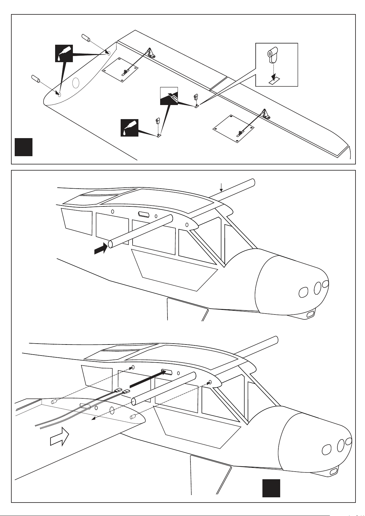
WING
BOTTOM - VIEW / Unteransicht
CA
Cut away only
the covering
CA
L/R
Assemble left and right
wing halves the same way
WING
Slide the aluminum tube into
the fuselage as shown.
Aluminum tube
L/R
Do the same way with other
wing halves.
Page 14
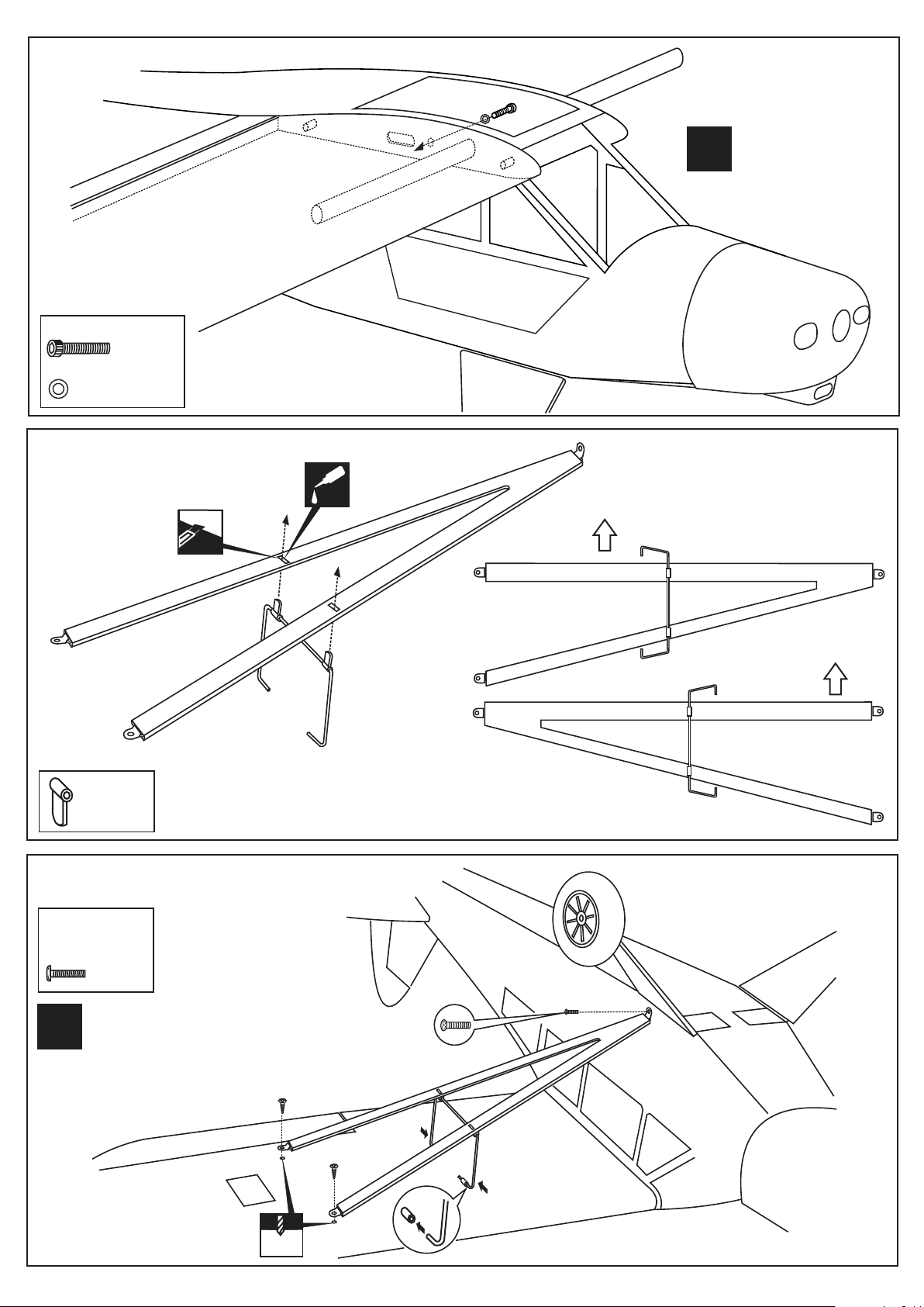
WING
5x20mm
5mm washer
..................2
WING
.......2
Secure the wing halves in place
using 5x20mm screw.
Do the same way with
L/R
other wing halves.
Cut away only
the covering
.........4
WING
3x12mm
.........4
3x12mm
.........2
CA
BOTTOM - VIEW / Unteransicht
FRONT
LEFT BRACE (TOP VIEW)
FRONT
RIGHT BRACE (TOP VIEW)
L/R
3x12mm
Do the same way with other
wing halves.
1.5mm
Page 15
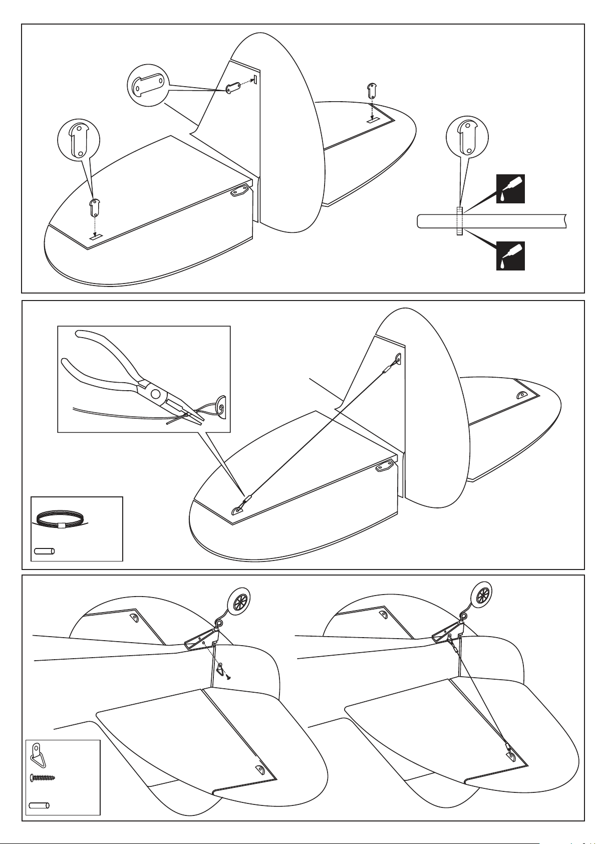
TAIL
TAIL
CA
Stabilizer
CA
0.7mm dia. Cable
2mm metal tube
.....................4
TAIL
..............2
3x6.......2
2mm metal tube
..............4
...1 roll
BOTTOM - VIEW
Unteransicht
Page 16
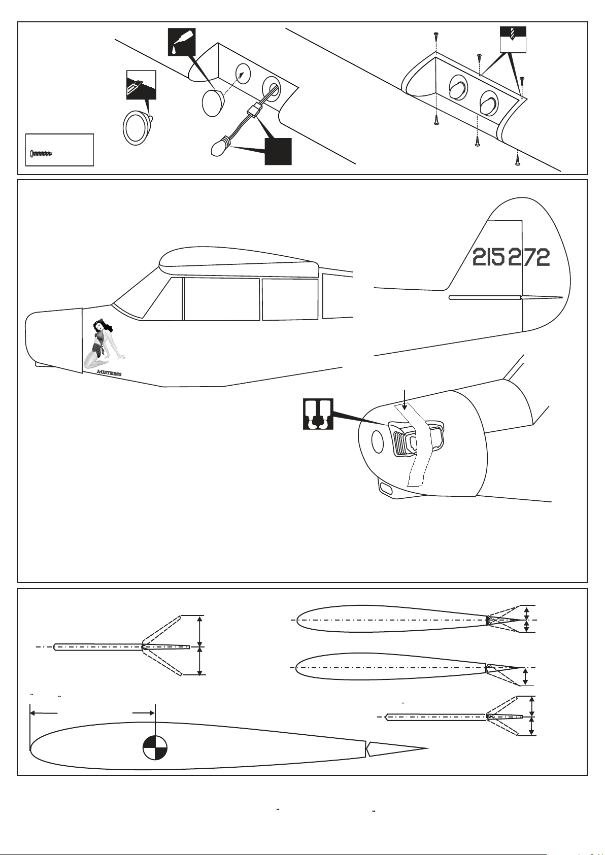
LIGH
2x6mm
DECOR
..........6
FUEL
12 US. GALS
100 OCTANE
CA
US.ARMY LK4A
AIRFORCE SERIAL NO 44 74298
1mm
X
Masking tape
A
B
5 min. Epoxy
Note: Cut out the stickers and apply them in the proper area. Do not peel the backing paper off all at once. Peel off one corner of the backing and cut off with
scissors. Arrange sticker on model and when satisfied adhere the corner without backing.
Carefully peel back the rest of the backing while at the same time adhering the rest of the sticker.
Try not to make air bubbles, if there are some, carefully puncture sticker (center of bubble) but not model surface with the tip of the knife or sharp pin and
squeeze out the air.
At curves stretch sticker and apply a little heat so that no ceases occur. Cut off the excess that is produced.
BALANCE
Aileron
Querruderausschlag
15mm
Rudder
Seitenruderausschlag
30mm
Flap
30mm
15mm
20mm
Do not try to fly an out-of balance model!
Uberprufen Sie vor dem Flug den Schwerpunkt.
95 ~ 100mm
Elevator
Hohenruderausschlag
15mm
15mm
IMPORTANT:
Please do not clean your model with pure alcohol, only use liquid soap with water or use glass cleaner to clean on surface of
your model to keep the colour not fade.
All details are subject to change
without notice !
Technische Anderungen und Irrtumer
vorbehalten !
 Loading...