

Page 1
Radio control model
R/C Flugmodell
MONTAGEANLEITUNG
INSTRUCTION MANUAL
SPECIFICATIONS
Wingspan 1220mm.
Length 1000mm.
Electric Motor (See next page)
Radio 4 Channel / 4 Servos
WARNING! This radio controlled model is NOT a toy. If modified or flown carelessly it could go out of controll and
cause serious human injury or property damage. Before flying your airplane, ensure the air field is spacious enough.
Always fly it outdoors in safe areas and seek professional advice if you are unexperienced.
ACHTUNG! Dieses ferngesteuerte Modell ist KEIN Spielzeug! Es ist für fortgeschrittene Modellflugpiloten bestimmt,
die ausreichende Erfahrung im Umgang mit derartigen Modellen besitzen Bei unsachgemäßer Verwendung kann
hoher Personen- und/oder Sachschaden entstehen. Fragen Sie in einem Modellbauverein in Ihrer Nähe um
professionelle Unterstützung, wenn Sie Hilfe im Bau und Betrieb benötigen. Der Zusammenbau dieses Modells ist
durch die vielen Abbildungen selbsterklärend und ist für fortgeschrittene, erfahrene Modellbauer bestimmt.
TECHNISCHE DATEN
Spannweite 1220mm
Lange 1000mm
Elektroantrieb (siehe nächste Seite)
Fernsteuerung 4 Kanal / 4 Servos
Designed for brushless electric motors
Entwickelt für Brushless Elektro Motoren
VQ No: VQA0100
THUNDERBOLT
Page 2
.........................................................
.........................................................
.........................................................
.........................................................
.........................................................
.........................................................
.........................................................
.........................................................
.........................................................
.........................................................
.........................................................
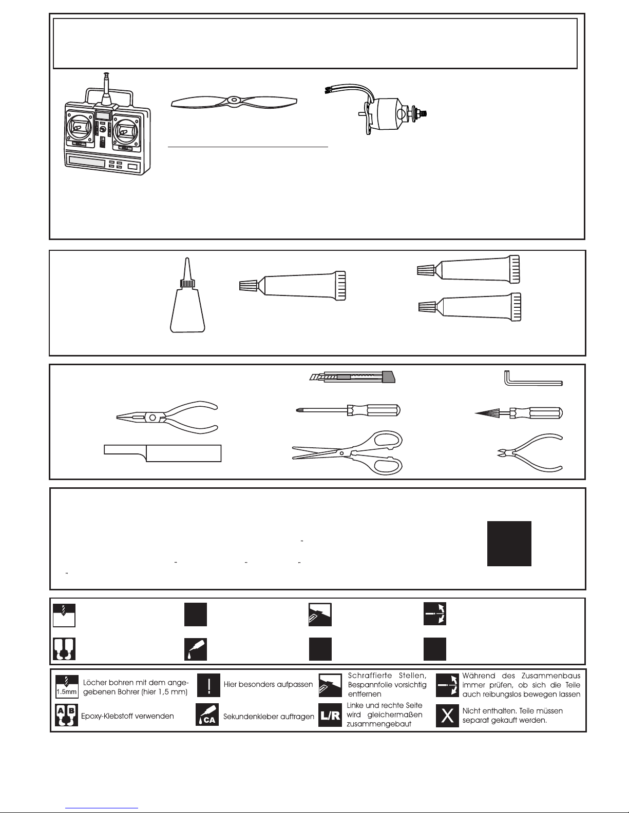
1.5mm
A
B
!
CA
L/R
Assemble left and right
sides the same way.
X
Drill holes using the stated
size of drill
(in this case 1.5 mm Ø)
Use epoxy glue
Take particular care here
Hatched-in areas:
remove covering
film carefully
Not included.
These parts must be
purchased separately
Check during assembly that these
parts move freely, without binding
Apply cyano glue
SILICON
EPOXY A
EPOXY B
CA
Epoxy Glue (30 minutes type)
Silicon Glue
Cyanoacrylate Glue
Sekundenkleber
Epoxy-Klebstoff (30min)
Silikonkleber
Tool Required/ Empfohlenes Werkzeug
The pre-covered film on ARF kit may wrinkle due to variations of temperature.
Store model in a cool and dry place for awile.
Then, staring with low heat, you may carefully use a hair dryer to smooth out wrinkels.
Die Bespannung des Modells kann durch Temeratureinflusse erschlaffen oder Falten
werfen z.b bei zu starker Sonnenenstrahlung oder Hitze.
Stellen Sie das Modell zunachst an einen kuhlen Platz fur eine bestimmte Zeit. Danach
konnen Sie versuchen die restlichen Falten vorstichtig mit einem Haartrockner zu behandeln.
!
CONVERSION TABLE
1.0mm = 3/64”
1.5mm = 1/16”
2.0mm = 5/64”
2.5mm = 3/32”
3.0mm = 1/8”
4.0mm = 5/32”
5.0mm = 13/64”
6.0mm = 15/64”
10mm = 13/32”
12mm = 15/32”
15mm = 19/32”
20mm = 51/64”
25mm = 1”
30mm = 1-3/16”
45mm = 1-51/64”
4 - channel radio
RECOMMENDED ACCESSORIES
4 - Kanal
Fernsteuerung
MASTER, No. 5374
Empfohlenes Zubehör
Antrieb Tuning (Kraftvoller Kunstflug):
BOOST 25 Brushless Combo Set, No. C2981
LiPo Akku RED POWER 2200-3S, No. C2158
Propeller 10*5, No. C5749
4 x Servo S2112
mit 500mm Servokabel
Page 3
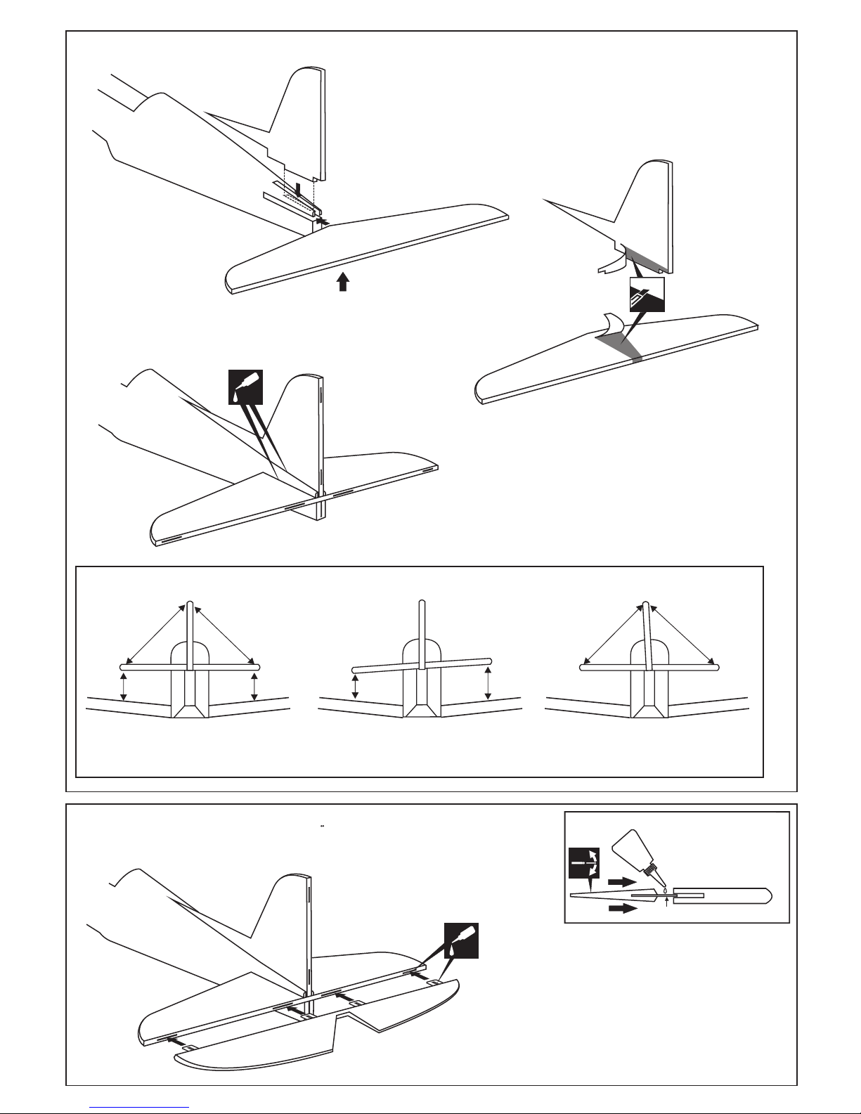
Cut away only the
covering both the
left and right side*
Note: Check the alignment of the horizontal stabilizer by measuring from
a fixed point along the center line of the fuselage to the leading edge on
each side of the horizontal stabilizer. The distance must be equal on both
sides. If not, adjust the stabilizer until the measurements are the same.
1-Slide the vertical and horizontal stabilizer on the fuselage, use a pencil to trace
around the bottom and the top (horizontal stabilizer) and the right and the left
(vertical stabilizer).
2-Remove the vertical and horizontal stabilizer from the fuselage. Careful cut
away the covering inside the lines which were marked in steep 1.
Cut away only the covering both
the top and bottom side*
Realign the vertical stabilizer and horizontal stabilizer, then glue
the vertical stabilizer and horizontal stabilizer into the fuselage,
using a generous amount of thin CA.
Note: glue both the right and left of the vertical stabilizer, and
both the top and bottom of the horizontal stabilizer.
CA
Thin CA
Attach the Vertical Stabilizer and the Horizontal Stabilizer
Incorrect
Correct
Incorrect
A
A’
A=A’
A
A’
A=A’
/
B
B’
B=B’
/
B
B’
B=
B’
CA
Thin CA
Push the elevator and its hinges into the hinge slots in the trailing
edge of the horizontal stabilizer.
There should be a minimal hinge gap.
When satisfied with the and alignment, hinge the elevator to the
horizontal stabilizer using thin CA glue.
Hinge
STABILIZER
CA
Apply thin CA to both
side of the hinge
WARNING! Securely glue together.
If coming off during flights, you lose control
of your airplane which leads to accidents !
Vergewissern Sie sich, sauber geklebt zu haben.
Andernfalls konnen Probleme mit der Flugeigenschaft
auftreten!
1
1A
1B
1C
2
Page 4

CA
Thin CA
Note: The slots for the control horn
installation are pre- cut at factory.
Control horn
...........1
CA
WARNING! Securely glue together.
If coming off during flights, you lose control
of your airplane which leads to accidents !
Vergewissern Sie sich, sauber geklebt zu haben.
Andernfalls konnen Probleme mit der Flugeigenschaft
auftreten!
CA
Thin CA
Hinge
STABILIZER
CA
Apply thin CA to both
side of the hinge
Push the rudder and its hinges into the hinge slots in the trailing edge of the
horizontal stabilizer. There should be a minimal hinge gap.
When satisfied with the and alignment, hinge the elevator to the horizontal
stabilizer using CA glue.
A
B
A
A=30mm
2mm
Drill a 2mm diameter hole in torque rod
mounting slot, marking sure that you
drill the hole perpendicular to the leading
edge of the rudder.
25mm tail wheel
2mm collar
CA
Thin CA
5 minute
3
4
4A
4B
5
5A
5B
Page 5

FUSELAGE - BOTTOM VIEW
The holes for the rudder servo
are Pre-cut at factory..
Cut away only the covering
6
6A
FUSELAGE - BOTTOM VIEW
6B
Rudder linkage
FUSELAGE - BOTTOM VIEW
Elevator linkage
6C
7
7A
Square plastic
Ply gear mount
plate
Gear mount
(hard wood)
Plastic strap
7B
7C
7D
Square plastic
3X12mm screw
Using a ply gear mount plate as a template, mark the square
plastic where the holes are to be drilled (7A).
Page 6

CA
8
9
9A
9B
WING - BOTTOM VIEW
WING - BOTTOM VIEW
Retract landing gear
not included.
8A
WING - BOTTOM VIEW
8B
10
RECEIVER
ELECTRIC RETRACT
LANDING GEAR
ON
OFF
GEAR
EXTENDED POSITION
RETRACTED POSITION
1-Using the ply gear mount as a template, trace around the
outside edge of the ply gear mount, and then remove it.
2-Using a sharp hobby knife, cut away the covering and balsa
along the lines.
Ply gear mount
Page 7

11
CA
CA
12
13
NOTE: Do not glue the bottom hatch onto the
wing at this time.
WING - BOTTOM VIEW
Page 8

14
49mm
Note: Position the motor on to the fire-wall so the
distance from the prop hub to the fire wall is 49mm.
2x10mm screw
85~90 mm
15mm
8mm
10mm
10mm
Aileron /
Rudder
Elevator /
8mm
15mm
Querruderausschlag
Hohenruderausschlag
Seitenruderausschlag
Do not try to fly an out-of balance model!
Uberprufen Sie vor dem Flug den Schwerpunkt.
IMPORTANT:
Please do not clean your model with pure alcohol, only use liquid soap with water or use glass cleaner
to clean on surface of your model to keep the colour not fade.
All details are subject to change
without notice !
Technische Anderungen und Irrtumer
vorbehalten !
CG
15
 Loading...