

Page 1
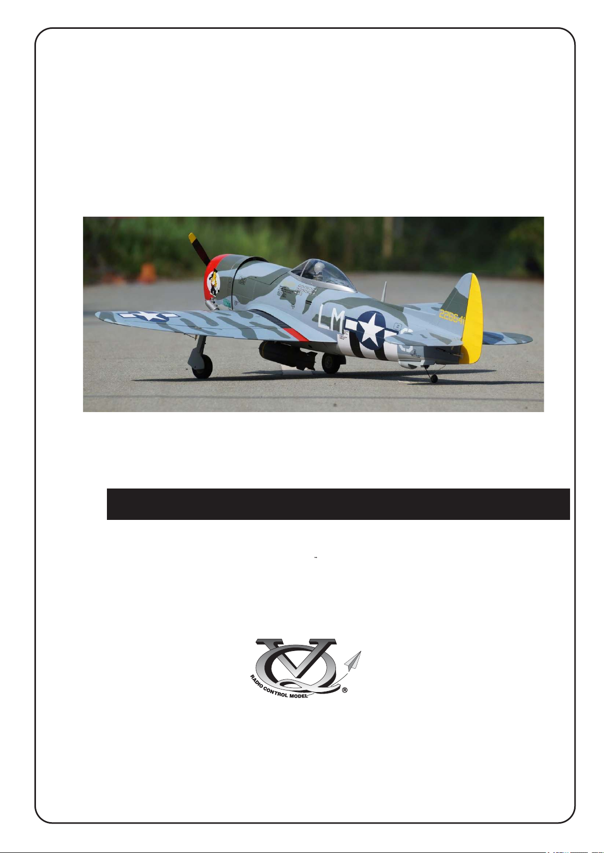
Radio control model / Flugmodel
P-47B/D THUNDERBOLT
VQA142DC
VQ No: VQA142DC
VQ No: VQA142DT
VQ No: VQA142BT
ALL BALSA, PLYWOOD CONSTRUCTION AND ALMOST READY TO FLY
Instruction manual / Montageanleitung
SPECIFICATIONS
Wingspan:......................................1480mm
Length:...........................................1215mm
Electric Motor:.....................See next pager
Glow Engine:.................... .46 2-T / .70 4-T
RTF Weight: 3.1Kg (will vary with equipment
use)
Radio:....................7 Channel / 7 Servos
Function: Ailerons-Elevator-Rudder-Throttle
Flaps.
WARNING! This radio controlled model is NOT a toy. If modified or flown carelessly it could go out of controll and
cause serious human injury or property damage. Before flying your airplane, ensure the air field is spacious enough.
Always fly it outdoors in safe areas and seek professional advice if you are unexperienced.
TECHNISCHE DATEN
Spannweite:...................................1480mm
Lange:............................................1215mm
Elektroantrieb.............(siehe nächste Seite)
Verbrennerantrieb:...............7.45cc - 11.5cc
Fluggewicht:.......................................3.1Kg
Fernsteuerung..........7 Kanal / 7 Servos
ACHTUNG! Dieses ferngesteuerte Modell ist KEIN Spielzeug! Es ist für fortgeschrittene Modellflugpiloten bestimmt,
die ausreichende Erfahrung im Umgang mit derartigen Modellen besitzen. Bei unsachgemässer Verwendung kann
hoher Personen- und/oder Sachschaden entstehen. Fragen Sie in einem Modellbauverein in Ihrer Nähe um
professionelle Unterstätzung, wenn Sie Hilfe im Bau und Betrieb benötigen. Der Zusammenbau dieses Modells ist
durch die vielen Abbildungen selbsterklärend und ist für fortgeschrittene, erfahrene Modellbauer bestimmt.
Page 2
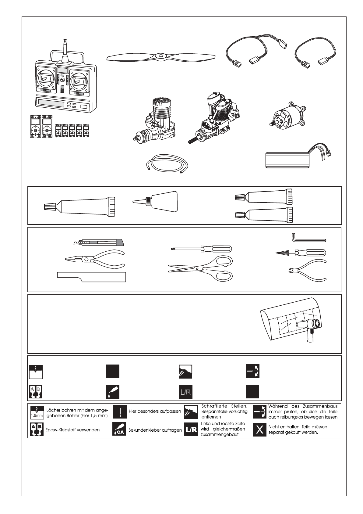
REQUIRED FOR OPERATION (Purchase separately)
Standard
Mini
Minimum 7 channel radio
Elevator : 1 standard servo
Rudder: 1 standard servo
Aileron: 2 mini servo
Flaps: 2 mini servo
Throttle: 1 mini servo (for glow engine only)
GLUE
(Purchase separately)
SILICON
Silicon sealer
TOLLS REQUIRED
Hobby knife
Needle nose Pliers
Sander
Masking tape - Straight Edged Ruler - Pen or pencil - Drill and Assorted Drill Bits
(Purchase separately)
.........................................................
.........................................................
.........................................................
.........................................................
.........................................................
.........................................................
.........................................................
.........................................................
.........................................................
.........................................................
.........................................................
.46 ~ .50 - 2 cycle
.72 ~.82 - 4 cycle
Silicone tube
CA
Cyanoacrylate Glue (thin type)
Phillip screw driver
Scissors
Flap: “Y” x2 pcs
Aileron: “Y”x1pcs
700-800W Brushless Motor
5 cell 4500mAh LiPo battery
EPOXY A
EPOXY B
Hex Wrench
Wire Cutters
Aileron: 50cmx2 pcs
Flap: 30cmx2 pcs
Rx battery pack: 20cmx1 pcs
Epoxy Glue
(30 minute type)
Awl
If exposed to direct sunlight and/or heat, wrinkels can appear. Storing the
model in a cool place will let the wrinkles disappear. Otherwise, remove
wrinkles in covering film with a hair dryer, starting with
low temperature. You can fix the corners by using a hot iron.
Bei Sonneneinstrahlung und/oder Wärme kann die Folie erschlaffen bzw. Falten
entstehen. Verwenden Sie ein Warumluftgebläse (Haartrockner) um evtl. Falten aus der Folie
zu bekommen. Die Kanten können Sie mit einem Bügeleisen behandeln. Nicht zuviel Hitze anwenden !
Symbols used throughout this instruction manual, comprise:
Drill holes using the stated
1.5mm
size of drill
(in this case 1.5 mm )
A
B
Use epoxy glue
Take particular care here
!
Apply cyano glue
CA
Hatched-in areas:
remove covering
film carefully
Assemble left and right
L/R
sides the same way.
Check during assembly that these
parts move freely, without binding
Not included.
These parts must be
X
purchased separately
Read through the manual before you begin, so you will have an overall idea of what to do.
CONVERSION TABLE
1.0mm = 3/64”
1.5mm = 1/16”
2.0mm = 5/64”
2.5mm = 3/32”
3.0mm = 1/8”
4.0mm = 5/32”
5.0mm = 13/64”
6.0mm = 15/64”
10mm = 13/32”
12mm = 15/32”
15mm = 19/32”
20mm = 51/64”
25mm = 1”
30mm = 1-3/16”
45mm = 1-51/64”
Low seting
Page 3
P-47 THUNDERBOLT
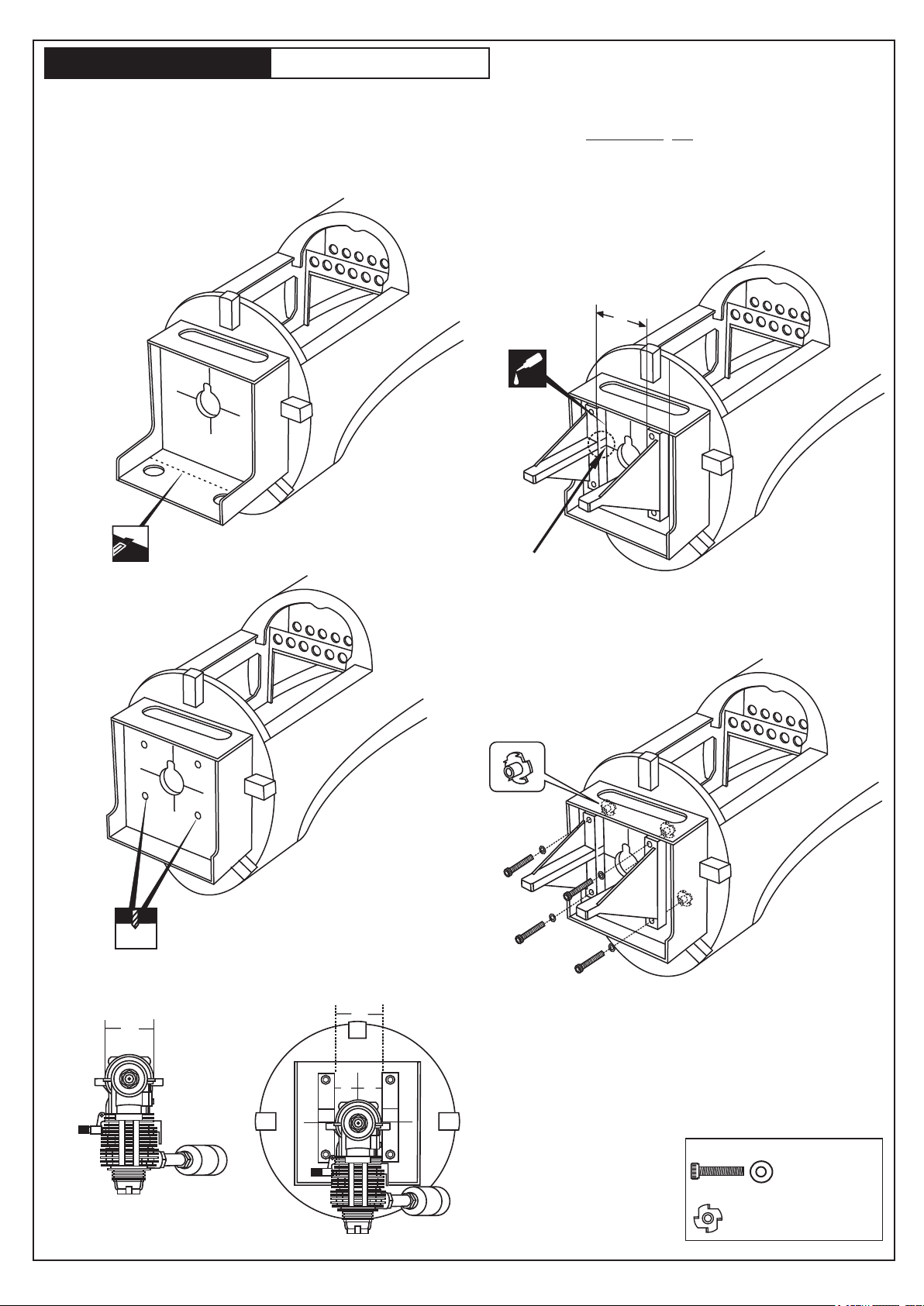
Push left (or right) the magnetic fuel tank hatch
and full it out of the fuselage.
Cut the wood along the line as shown
(1A) in case of 4T engine using
1- ENGINE MOUNT
1A
Attach the engine mount beams onto the fire-wall
so the distance between of two engine mount beams
is “A”,and B=B’ as show.
Secure the engine mount beams onto the fire-wall
with litter CA glue (1B)
! Align the mark on both engine mount
beams with the mark on the fuselage
Using a pencil or felt tipped pen, mark
the fire wall where the four holes are to
be drilled(1B))
A
Liter
CA
1B
6mm
A
In case of 4T
glow engine
using.
! Align the mark on both
engine mount beams with
the mark on the fire-wall.
1C
Carefully remove the engine mount beams
and drill a 6mm hole through the fire-wall
at each of the four marks made above (1C)
FRONT-VIEW
A
B’
B
B=B’
1D
Insert the blind-nut onto each
of the four holes make above (1D).
Reposition the engine mount beams on to the fire-wall
and secure them with four 4x25mm screw (1D)
4x25mm screw - washer
...................4
Blind-nut
....................4
Page 4
P-47 THUNDERBOLT
C=125mm
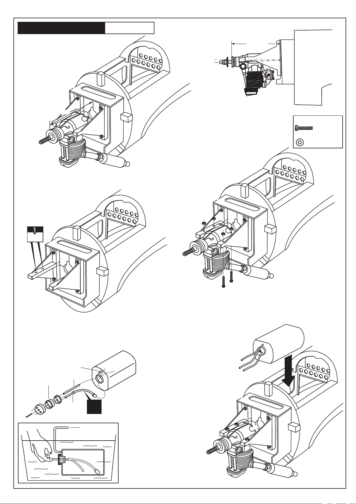
2- ENGINE
2A
Position the engine to the engine mounts so the distance from the prop hub
to the fire-wall is 125mm.
Mark the engine mounting plate where the four holes are to be drilled (2A)
C
125mm
! Engine thrust on balk head
is already adjust at factory
FUSELAGE
SIDE-VIEW
3x25mm screw
.......4
Washer
.......4
3mm
2B
Remove the engine and drill a 3mm holes through the beam at each
of the four marks made above (2B)
Marking sure that you drill the hole perpendicular to the beam of the
engine mount.
To muffler
2D
Rubber stopper
3x35mm screw
Filler tube
To engine
X
3x25mm
Reposition the engine on the engine mount beams, aligning
it with the holes. Secure the engine to the engine mount using
four 3x25mm screws (2C)
Note: Apply Silicon sealer to each of the
3x25mm screw and nut.
2F
Carefully install the fuel tank
to ensure that they will not
shift during flight (2F).
2C
Water
Blow
2E
Checking for leaks - block the vents
and blow into the feed - if in doubt
submersing the tank in a blow of
water will show up any problems.
Page 5
P-47 THUNDERBOLT
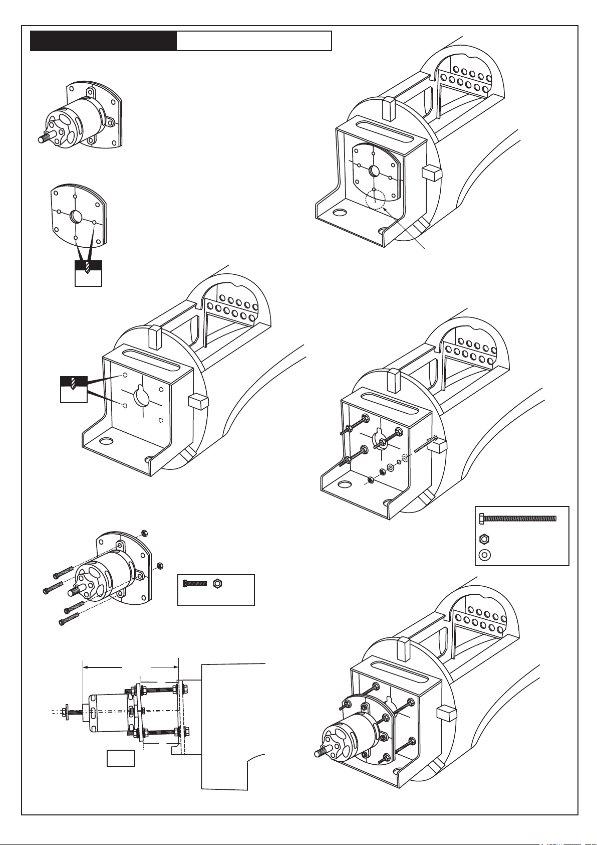
Using a aluminum motor mounting plate
as a template, mark the plywood motor
mounting plate where the four holes are
to be drilled.
3A
Remove the aluminum motor mounting
plate and drill a 1/8”(3mm) hole through
the plywood at each of the four marks
marked .
3B
3mm
3- ELECTRIC MOTOR
Using a wooden motor mounting plate as a template,
mark the fire-wall where the four holes are to be drilled (3C).
! Align the mark on wooden motor
mounting plate with the mark on
3C
the fire-wall.
6mm
3D
Remove the wooden motor mounting
plate and drill a 6mm hole through
the fire-wall at each of the four marks
marked (3D) .
3F
Secure the Motor to the wooden
motor mounting plate using the
four 3mm bolts.
3mm bolt / nut...4
SIDE-VIEW / Seitenansicht
C
125mm
B
3E
Attach the four 5x70mm bolts
and nuts to the fire-wall as
shown (3E).
3G
6x100mm bolt.....4
6mm nut..........12
6mm washer...16
B’
B=B’
! Motor thrust on balk head
is already adjust at factory
FUSELAGE
SIDE-VIEW
Page 6
P-47 THUNDERBOLT
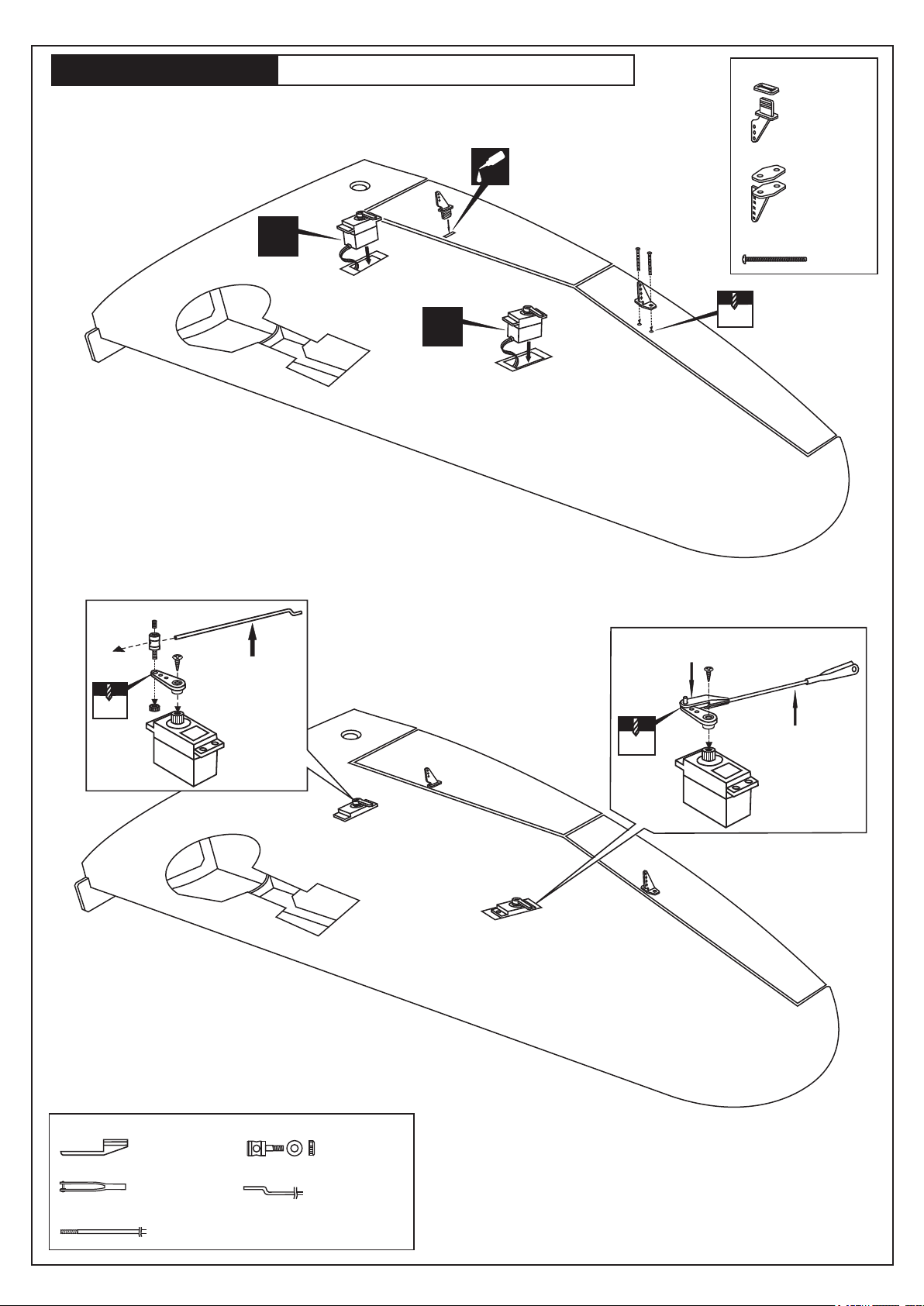
4- WING: SERVO AND LINKAGES
Secure the plastic control horn
in place using the thin CA glue.
Thin CA
CA
Cut away only
the covering
Plastic control horn
............2 set
Plastic control horn
............2 set
X
Using the thread (pre-installed at factory)
to slide the aileron and flap extension cord
(not include) into the wing half.
connector
Flap push-rod
1.2x120mm
2 mm
Flap servo
X
2 mm
2x20mm screw
......4
2 mm
EZ link
Aileron push-rod
2X175mm
Plastic EZ link
............2
Steel clevis
............2
Aileron push rod 2x175mm
.....2
Connector
2mm
............2
Flap push rod 1.2x120mm
............2
Aileron servo
Page 7
P-47 THUNDERBOLT
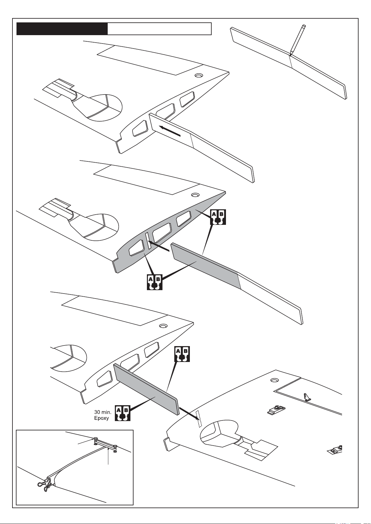
5- JOINNING THE WING
Draw the center line
on the wing joiner
Without using Epoxy yet, trial fit the wing joiner into one
of the wing panels.
Next, slide the other wing half onto the dihedral brace until the
wing panels meet. If the fit is overly tight, it may be necessary
to lightly sand the dihedral brace.
30 min.
Epoxy
Coat one half of the dihedral brace with epoxy up
to the center line. Install the epoxy-coated side of
the dihedral brace into the wing joiner cavity up to
the center line.
Carefully slide the wing halves together, ensuring that
they are accurately aligned.
Firmly press the two halves together, allowing the excess epoxy
to run out. Using a paper towel, clean off the excess epoxy.
Nylon wing bolt
(included)
Paper clamp
(not include)
Rubber band
(not include)
Hold the wing halves together with paper
clamp and rubber band.
Page 8
P-47 THUNDERBOLT
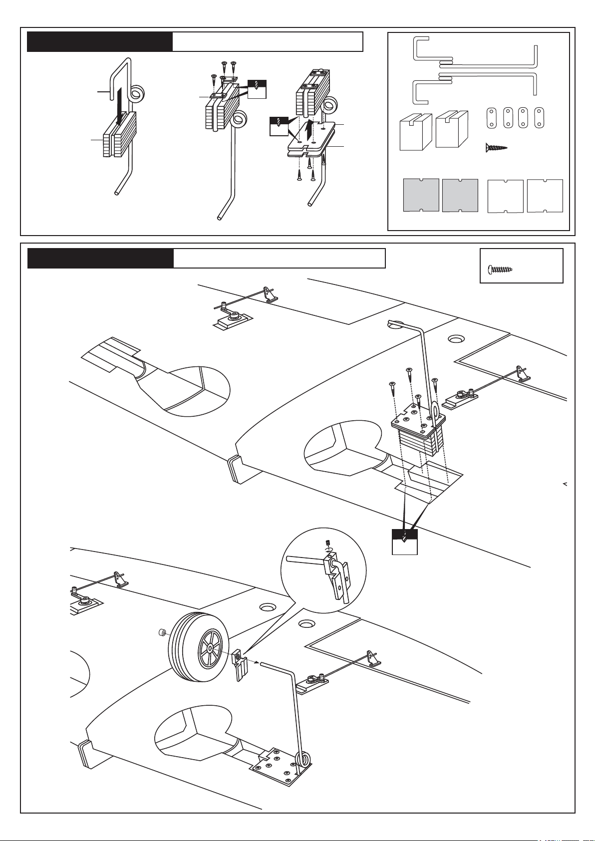
6- FIXED GEAR ASSEMBLY
3x20mm
Main gear (left)
Main landing gear
Gear mount
1
P-47 THUNDERBOLT
Nylon gear
strap
2
2mm
2mm
3x20mm
3
7- FIXED GEAR INSTALLATION
Ply gear
mount flat
Square
plastic
Main gear (right)
Gear mount
(plywood)
Ply gear mount plate
Plastic strap
3x20mm screw..16
Square plastic
3x10mm screw
..........8
5/64”
2mm
Do the same way with
second wing half.
Page 9
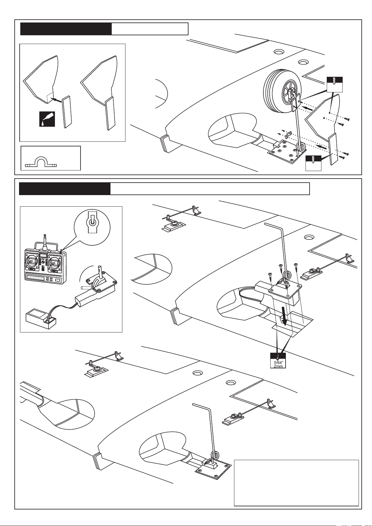
P-47 THUNDERBOLT
In case of fixed gear using
8- GEAR DOOR
1.5mm
CA
Plywood gear cover
Plastic strap
........2
P-47 THUNDERBOLT
ON
OFF
GEAR
SWITCH
EXTENDED
RETRACTED
plastic strap
Do the same way with
second wing half.
9- ELECTRIC RETRACT GEAR INSTALLATION
2x6mm
screw
1.5mm
Electric retract must be purchase separately
Do the same way with
second wing half.
Important: When you “on” the retract swicth,
if the retract gear does not retracted completely,
use your finger to push the retract gear to the
completely retrated position, it will extend.
Then use the hobby knife to remove the place
where the retract gear is entangled.
Page 10
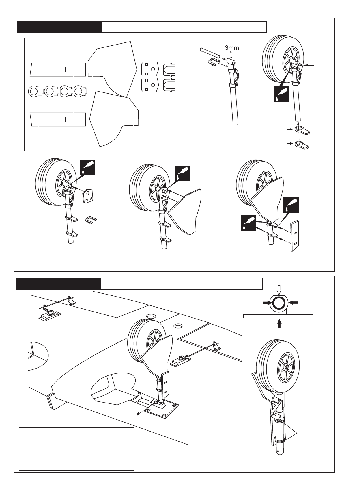
P-47 THUNDERBOLT
Wheel Cover Parts
3mm plywood
10- STRUT AND GEAR DOOR ASSEMBLY
G1
GP 1
GP 2
GP 2
GP 1
G2A
G2A
G2
G2
G2
G2
CA
G1
GP2
GP1
CA
CA
G3
GP2
G2A
G3
CA
G1
CA
GP1
Glue the G2A to the Strut and
G2, But do not glue the GP2
and GP1 to the Strut in this time.
P-47 THUNDERBOLT
Adjust the GP2 and GP1
Glue the G3 to the G2A
before glue them to the G1.
Glue the GP2 and GP1to
the Strut.
11- STRUT AND GEAR DOOR ASSEMBLY
3mm screw set
Sand here
Wooden ringStrut
Gear door
Important: When you “on” the retract swicth,
if the retract gear does not retracted completely,
use your finger to push the retract gear to the
completely retrated position, it will extend.
Then use the hobby knife to remove the place
where the retract gear is entangled.
Sand here
Lightly sand the wooden rings to be sure that
the struts locks in retracted position.
Page 11
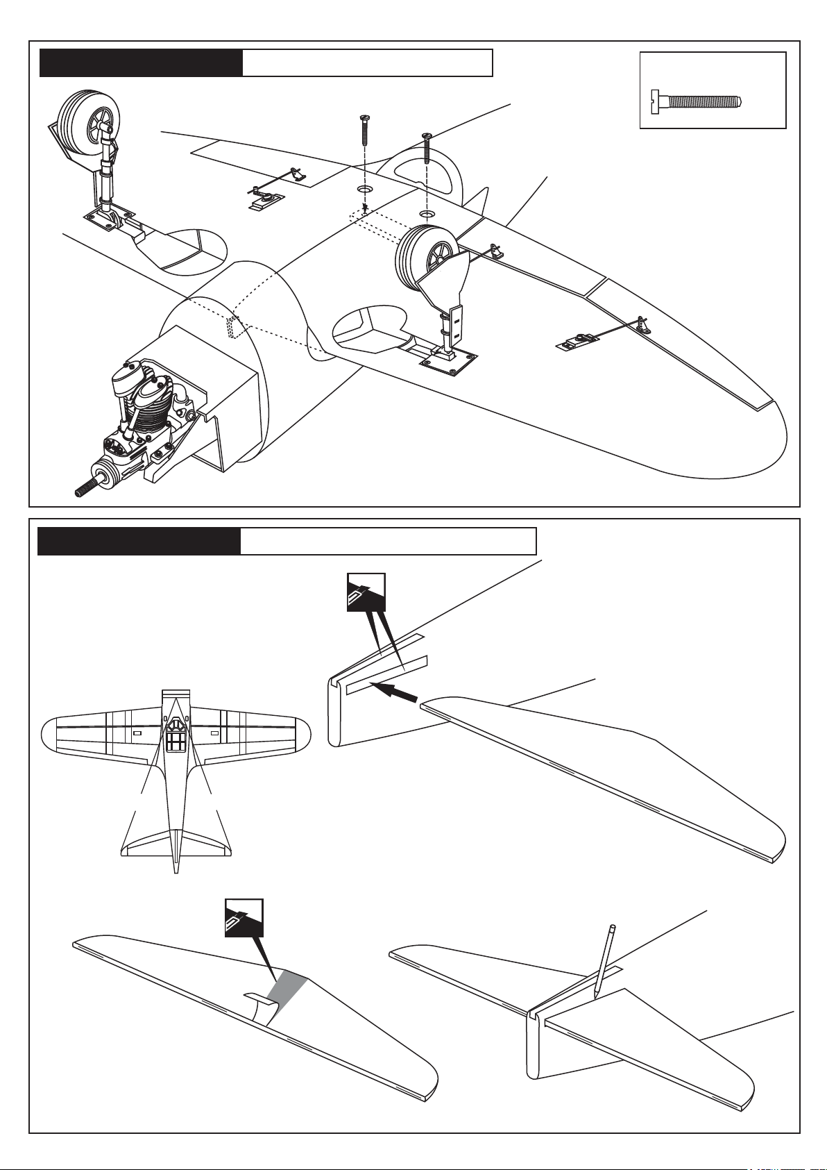
P-47 THUNDERBOLT
12- WING INSTALLATION
6x50mm nylon bolt
.....2
P-47 THUNDERBOLT
Push the horizontal stabilizer into the slot on the fuselage
as show. Check the alignment of the horizontal stabilizer
by measuring from a fixed point along the center line of
the fuselage to the leading edge on each side of the
horizontal stabilizer. The distance must be equal on both
sides . If not, adjust the stabilizer until the measurements
are the same (see picture below: A=A’).
13- STABILIZER INSTALLATION
A = A’
A
Cut away only
the covering
both side
A’
13D
Cut away only
the covering
13A
When you are satisfied with the alignment, use
13C
a pencil to trace around the top and bottom of
the stabilizer where it meets the fuselage .
Using a sharp hobby knife, carefully cut away
the covering around of all slots for the horizontal
stabilizer and vertical fin installation.
13B
Remove the left and right elevator out of the
horizontal stabilizer.
Remove the horizontal stabilizer
from the fuselage. Using a straight edge
and a sharp hobby knife, carefully cut away
the covering inside the lines which were marked
above. Be cautious not to cut into the wood-this
will weaken the structure .
Page 12
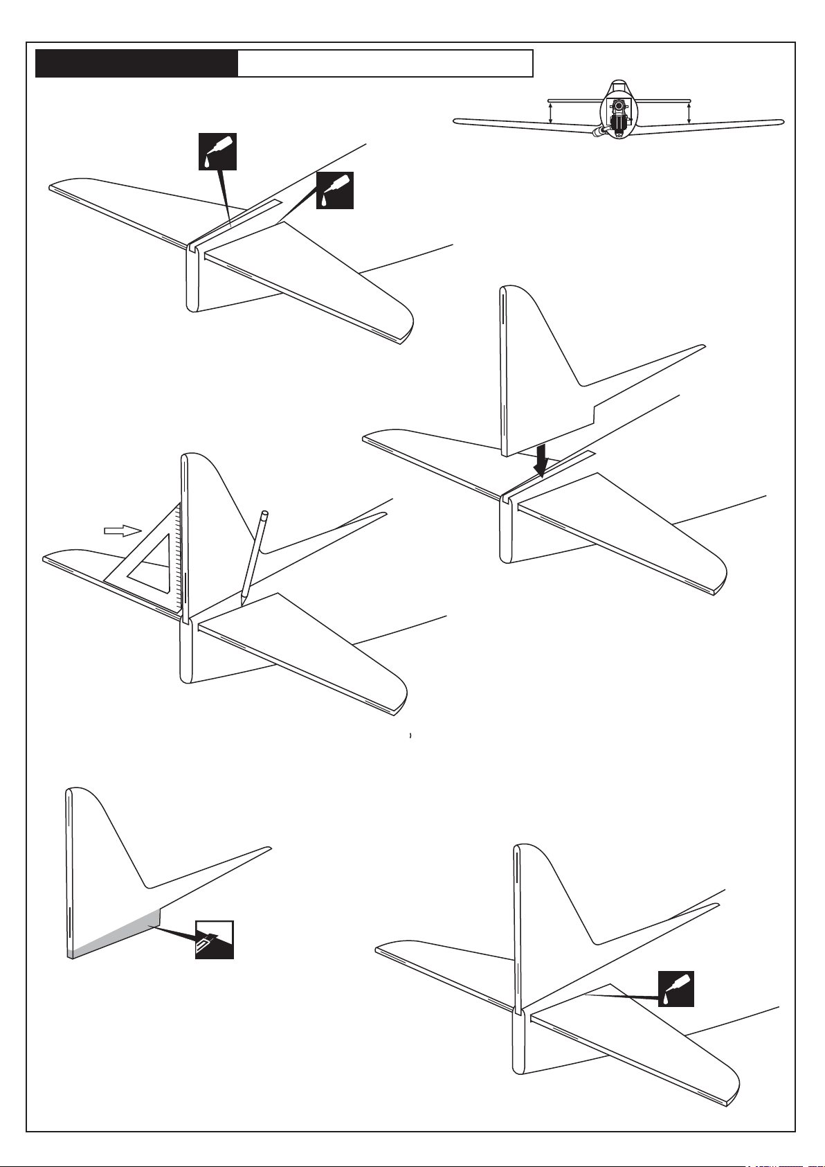
P-47 THUNDERBOLT
14- STABILIZER INSTALLATION
B=B’
Apply thin CA glue into the slot where
the fuselage meet the horizontal stabilizer.
CA
14A
14C
90 degree
triangle
Install the horizontal stabilizer onto the fuselage and adjust
Apply CA glue
both sides.
CA
(thin CA)
the alignment as described in steep 13A.
Note: it is important to ensure that the horizontal stabilizer is
also level in regards to the wing. The distance must be equal
on both sides. If not, adjust the stabilizer until the
measurements are the same.
Apply the thin CA along the area where the covering was
removed in the previous step and to the fuselage where the
horizontal stabilizer mounts .
14B
Pull the rudder out of the vertical fin.
Carefully, push the vertical fin into the
slot on the fuselage as shown (14B).
B
B’
Remove the vertical stabilizer from the fuselage.
Using s sharp hobby knife, carefully cut away the
covering below the lines which were drawn in the
previous steep. Do not cut into the woods as this
will affect the structural integrity of the stabilizer (14D).
14D
Cut away only
the covering
Trial fit the vertical fin in position. Using
a 90 degree triangle, ensure that the
vertical stabilizer is perpendicular to the
horizontal stabilizer (14C).
Using a pencil, trace around the vertical
stabilizer where it meets the fuselage.
Remove the vertical stabilizer from the
fuselage.
14E
Apply thin CA
glue both side
CA
Insert the vertical fin into the fuselage, precisely align the vertical stabilizer
as described in step 14C.
! Securely glue together. If coming off during fly, you lose control of your
air plane.
Page 13
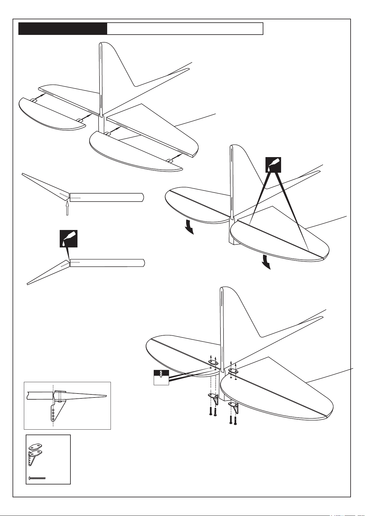
P-47 THUNDERBOLT
TOP-SIDE
HORIZONTAL STABILIZER
15- ELEVATOR AND CONTROL HORN
Without using glue yet, push the elevator
and its hinges into the hinge slots in
trailing edge of the horizontal stabilizer.
Apply thin CA
glue both side
CA
Apply a thin layer of petroleum jelly
Apply thin CA
glue on the top
CA
of the hinge
TOP-SIDE
HORIZONTAL STABILIZER
Do the same way with the bottom side
of elevator and with the second elevator.
2mm
Control horn
................2
2x12mm screw
..........4
Page 14
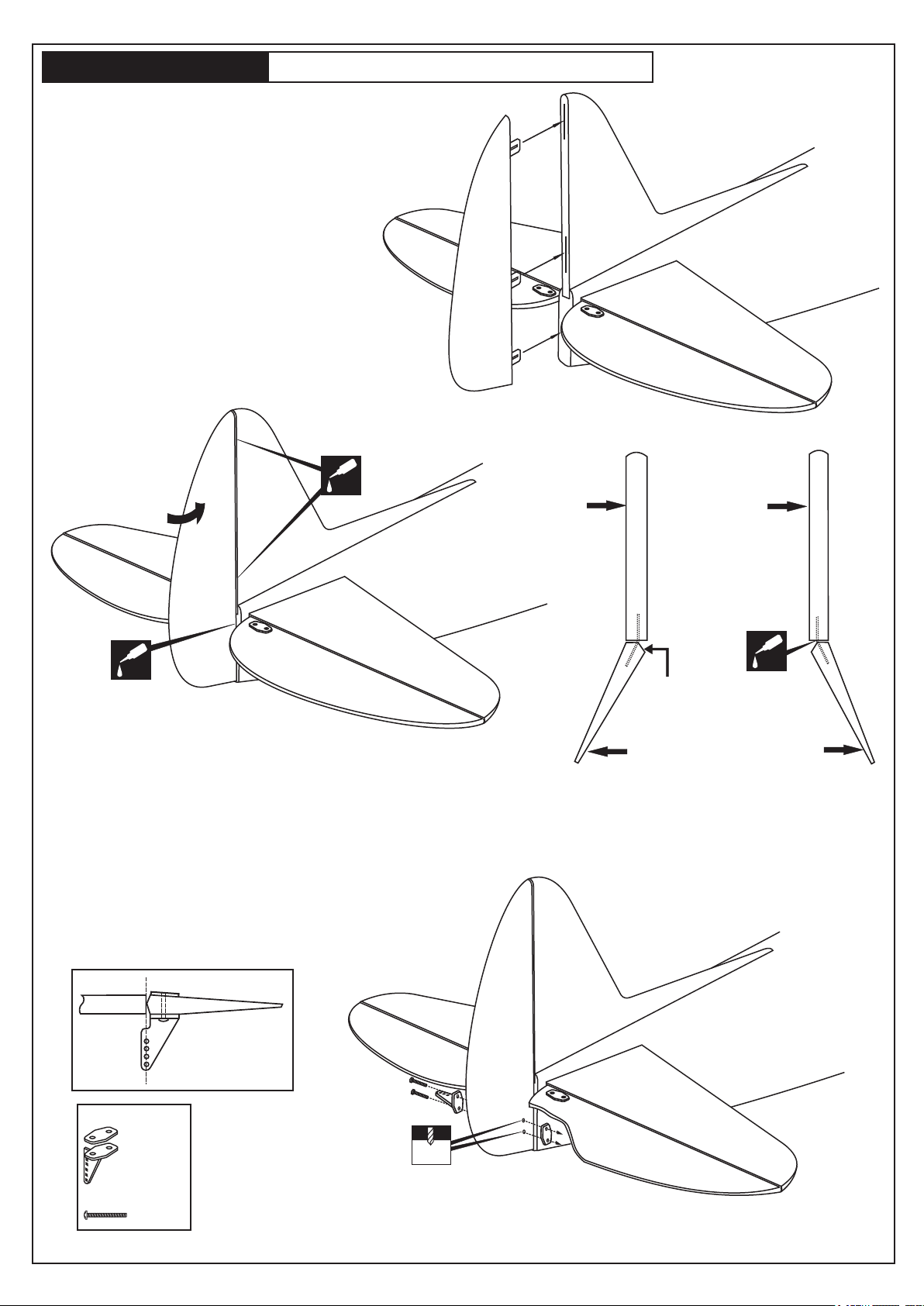
P-47 THUNDERBOLT
Without using glue yet, push the rudder
and its hinges into the hinge slots in
trailing edge of the vertical stabilizer.
16- RUDDER AND CONTROL HORN
Apply thin CA
glue both side
CA
Apply thin CA
glue both side
CA
Vertical
Stabilizer
Vertical
Stabilizer
Apply thin CA
glue on the left
and right
of the hinge
CA
Apply a thin layer
of petroleum jelly
RUDDERRUDDER
Control horn
................3
2x12mm screw
..........6
2mm
Page 15
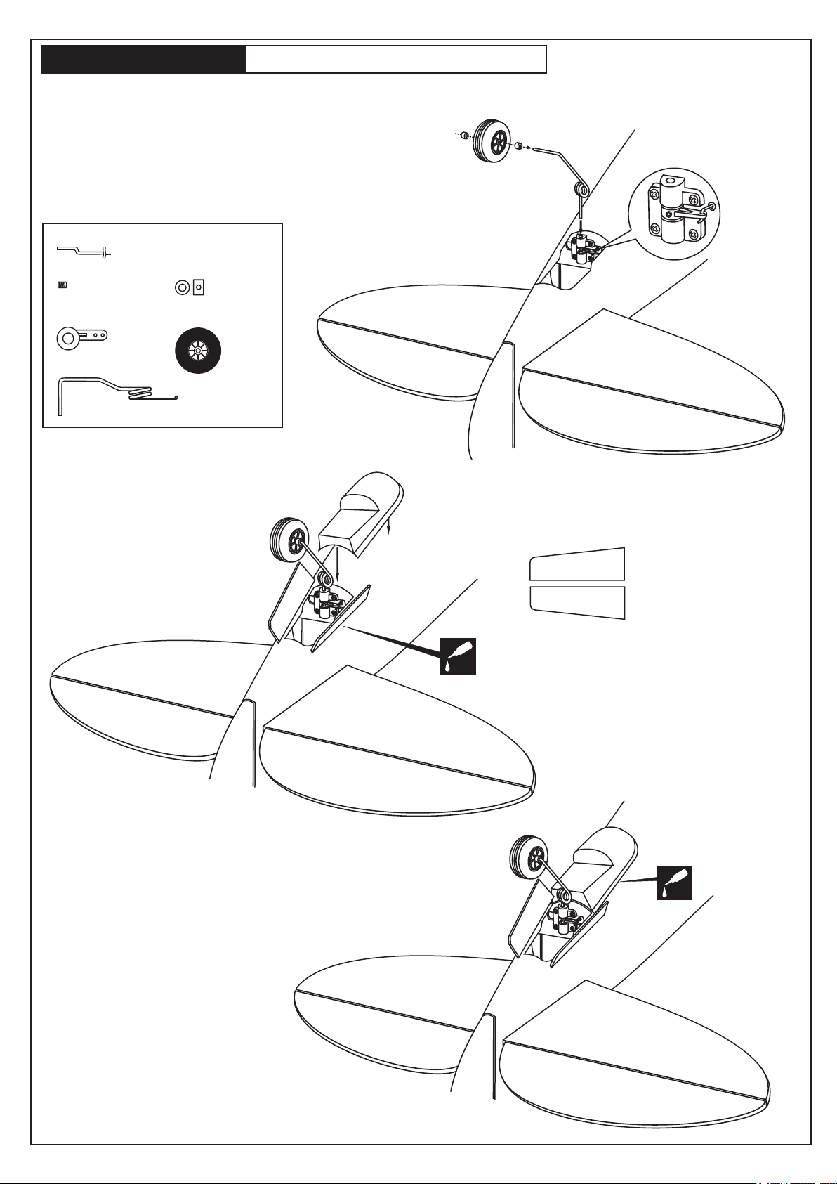
P-47 THUNDERBOLT
1- Insert the tail wheel pushrod into the hole on the tail gear
control horn (as show).
2- Install the tail wheel control horn in place.
3- Instal the tail wheel gear in place.
4- Secure the tail wheel control horn in place using a 5/64”(2mm)
screw set, Ensure smooth non-binding movement.
17- TAIL GEAR INSTALLATION
1.2x800mm rod
...................................1
3x3mm screw
............1
Tail wheel control-
horn
.................1
Tail landing gear
..........1
2mm I.D collar
...............2
25mm wheel
..........1
Plywood Tail wheel door
P-47
P-47
Attach the tail wheel doors
CA
in place using CA glue.
CA
Page 16
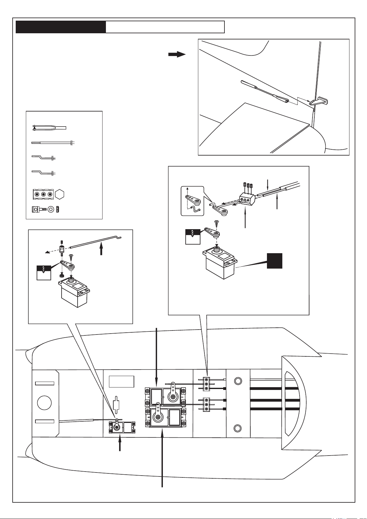
P-47 THUNDERBOLT
Insert the rudder push-rod from the rear of the fuselage.
Screw the clevis mid-thread, then connect to the rudder control horn.
Insert the two elevator push-rod from the rear of the fuselage.
Screw the clevis mid-thread, then connect to the elevator control horn.
Steel clevis
.......3
2x950mm rod
.......3
(2 x120mm) rod
............2
(1.2 x500mm) throttle rod
............1
Triple connector
................2
18- SERVO AND LINKAGES
3mm set Screw
Tail gear push-rod 1.2x800mm
2mm
....................1
Throttle push-rod
1.2x500mm
2 mm
Throttle servo
In case of Glow engine using
Rudder push-rod
2x950mm
Triple connector
2 mm
X
Cut the rudder push-rod excess length.
Cut the tail wheel push-rod excess length.
Insert all into the triple connector and tighten everything.
Do the same way with the elevator linkages.
Rudder servo
Throtlle servo
Elevator servo
FUELAGE BOTTOM-VIEW
Page 17
P-47 THUNDERBOLT
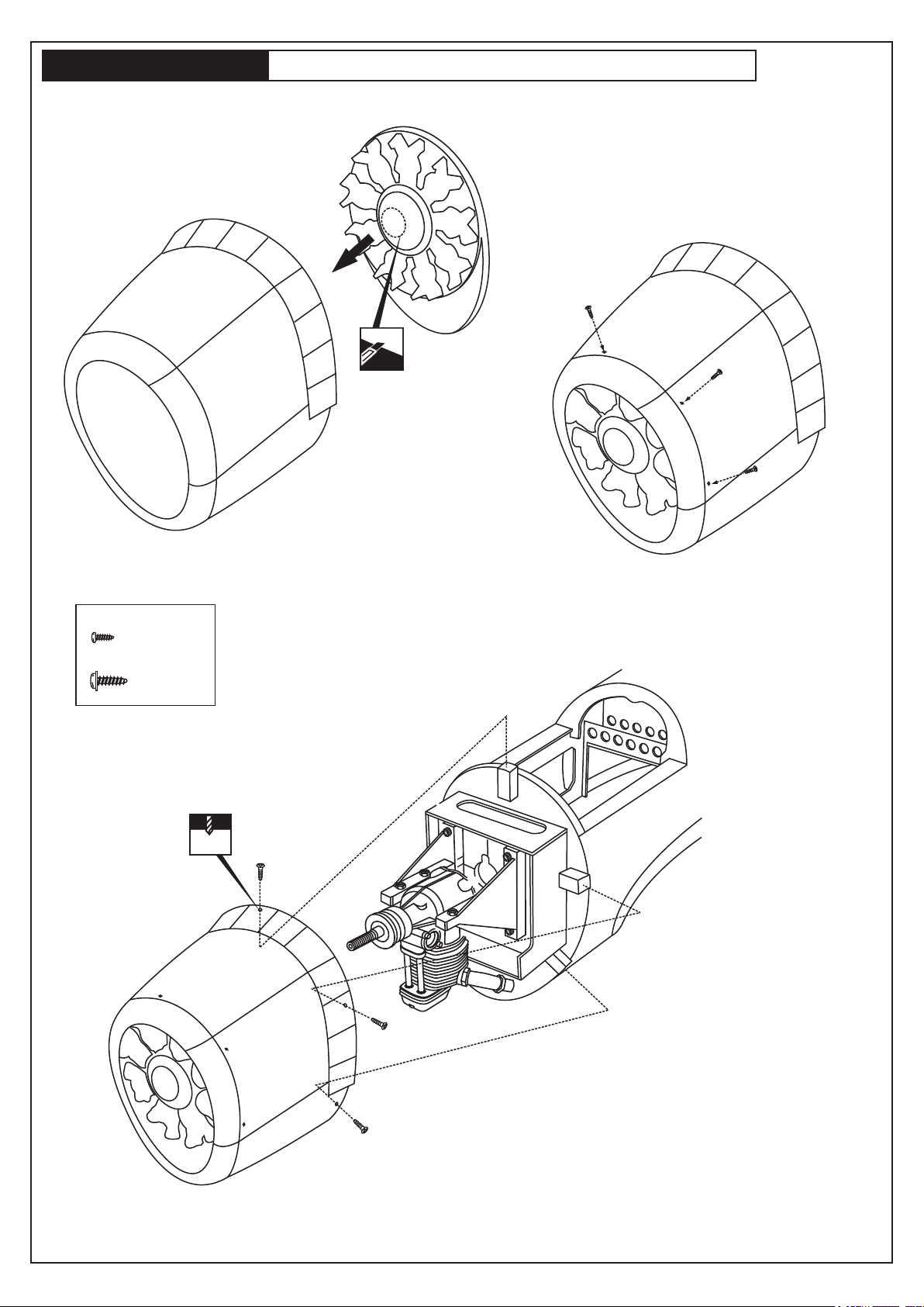
19- FIBERGLASS COWL AND DUMMY ENGINE
2x6mm screw
2x6mm screw
.........6
2.5x10mm screw
.........5
2mm
2,5X10mm
Page 18
P-47 THUNDERBOLT
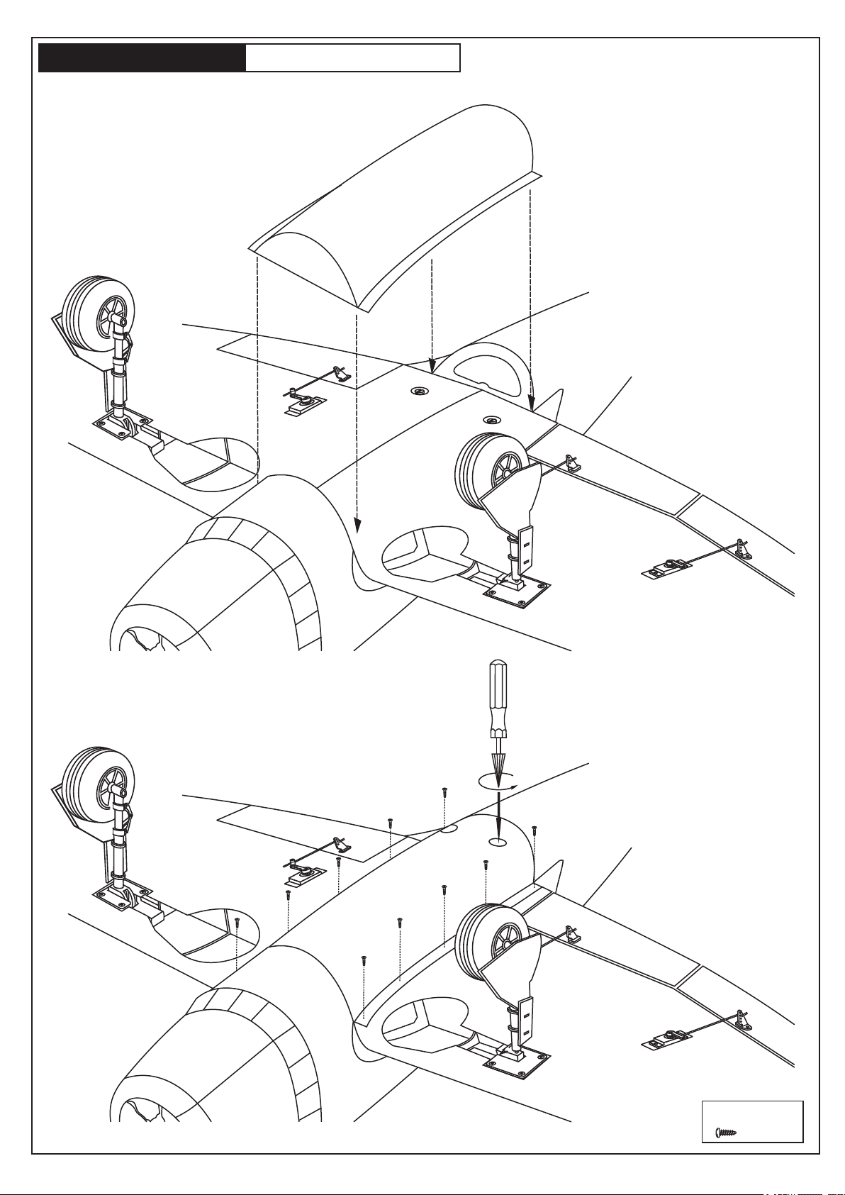
20- BOTTOM COVER
2x6mm self tapping screw
2x6mm screw
.........10
Page 19
P-47 THUNDERBOLT
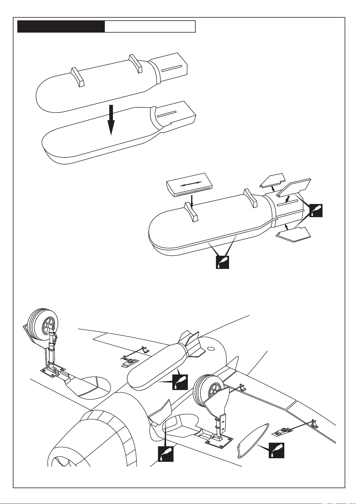
21- BOMB ASSEMBLY
Sander
CA
CA
CA
CA
CA
Page 20
P-47 THUNDERBOLT
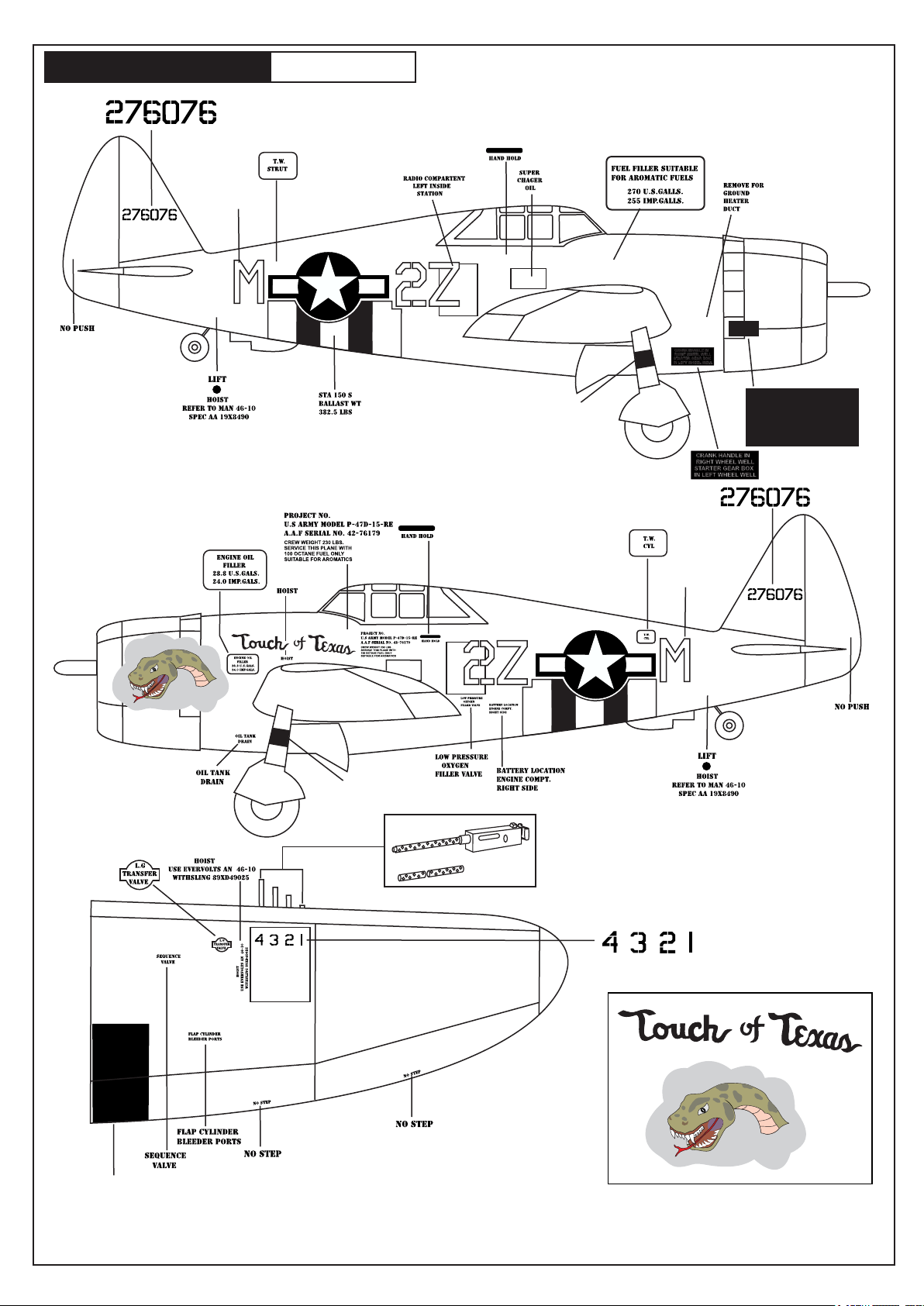
Sticker
22- STICKER
P-47B “Touch of Texas”
Black Sticker
BOLTS IN EXHAUST MANIFOLD CLAMPS
SHOULD BE TIGHTENED JUST BEYOND
FINGER TIGHTNESS AS FOLLOWS:
1- DRAW UP BOLTS FULL TIGHT WITH WRENCH.
2- BACK OF TILL LOOSE.
3- DRAW UP FINGER TIGHT AND THEN TAKE ABOUT
ONE FULL TURN WITH WRENCH.
4- CLAMPS SHOULD NOT ROTATE BY HAND BUT
CREEP UNDER MALLET TAPS.
5- THIS DOES NOT APPLY TO MARMAN CLAMPS.
BOLTS IN EXHAUST MANIFOLD CLAMPS
SHOULD BE TIGHTENED JUST BEYOND
FINGER TIGHTNESS AS FOLLOWS:
1- DRAW UP BOLTS FULL TIGHT WITH WRENCH.
2- BACK OF TILL LOOSE.
3- DRAW UP FINGER TIGHT AND THEN TAKE ABOUT
ONE FULL TURN WITH WRENCH.
4- CLAMPS SHOULD NOT ROTATE BY HAND BUT
CREEP UNDER MALLET TAPS.
5- THIS DOES NOT APPLY TO MARMAN CLAMPS.
Black Sticker
Sticker
Nose Art Sticker for P-47-B “Touch of Texas”
P-47B “TOUCH OF TEXAS” DECAL - VQ MODELS
Red Sticker
IMPORTANT: Please do not clean your model with strong solvent or pure alcohol to keep the
colour of your model not fade.
Page 21
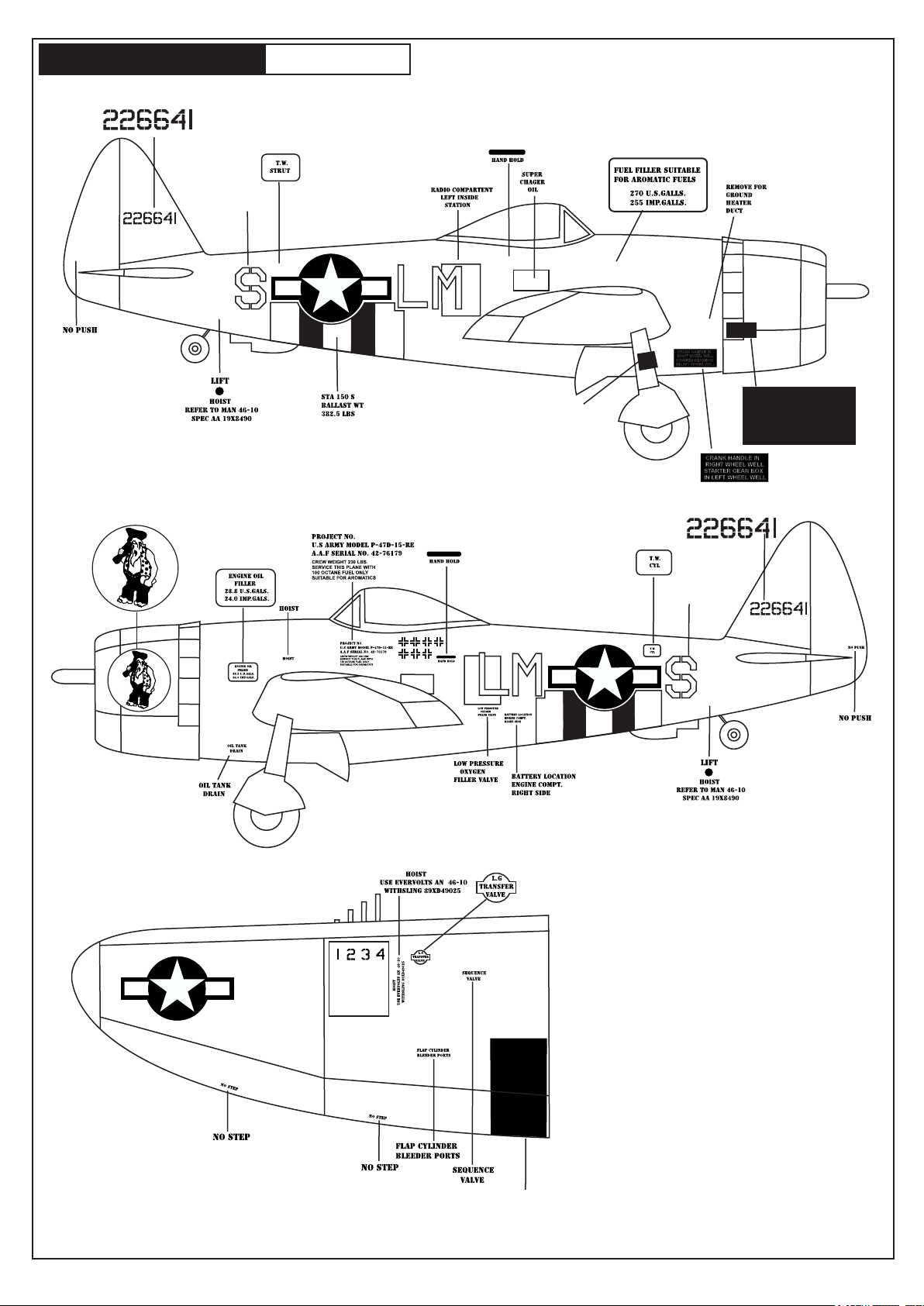
P-47 THUNDERBOLT
Sticker
23- STICKER
P-47D Camo. LM-Z
Black Sticker
BOLTS IN EXHAUST MANIFOLD CLAMPS
SHOULD BE TIGHTENED JUST BEYOND
FINGER TIGHTNESS AS FOLLOWS:
1- DRAW UP BOLTS FULL TIGHT WITH WRENCH.
2- BACK OF TILL LOOSE.
3- DRAW UP FINGER TIGHT AND THEN TAKE ABOUT
ONE FULL TURN WITH WRENCH.
4- CLAMPS SHOULD NOT ROTATE BY HAND BUT
CREEP UNDER MALLET TAPS.
5- THIS DOES NOT APPLY TO MARMAN CLAMPS.
BOLTS IN EXHAUST MANIFOLD CLAMPS
SHOULD BE TIGHTENED JUST BEYOND
FINGER TIGHTNESS AS FOLLOWS:
1- DRAW UP BOLTS FULL TIGHT WITH WRENCH.
2- BACK OF TILL LOOSE.
3- DRAW UP FINGER TIGHT AND THEN TAKE ABOUT
ONE FULL TURN WITH WRENCH.
4- CLAMPS SHOULD NOT ROTATE BY HAND BUT
CREEP UNDER MALLET TAPS.
5- THIS DOES NOT APPLY TO MARMAN CLAMPS.
Sticker
Red Sticker
Page 22
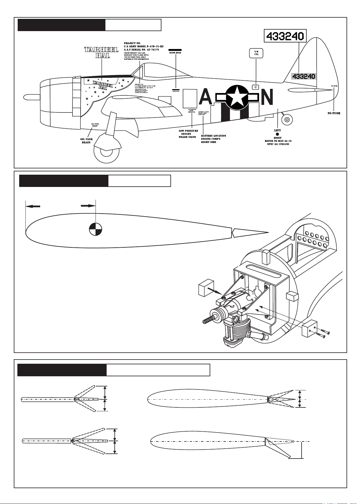
P-47 THUNDERBOLT
24- STICKER
P-47D “Tarheel Hal” IA-N
I
P-47 THUNDERBOLT
(88 ~ 93mm)
How to add nose weight
To get the correct C.G., Several strips of lead weight were
required in the nose of this model .
To minimize the amount of weight required, it is desirable to
position the weight as far forward as possible.
IMPORTANT: Recheck the C.G. After the weight has been installed.
25- BALANCE
Note: Adjust the location of the battery pack to achieve this C.G location.
Wing center section
DO NOT try to fly an out-of balance model!
Lead
Lead
P-47 THUNDERBOLT
ELEVATOR STROKE
RUDDER STROKE
Adjust the travel of the control surfaces to achieve the values stated in the diagrams.
These value will be suitable for average flight requirements. Adjust the values to suit your particular needs.
26- CONTROL SURFACE
(15mm)
(15mm)
AILERON STROKE
(25mm)
(25mm)
FLAPS STROKE
(10mm)
(10mm)
(25-30mm)
 Loading...