

Page 1
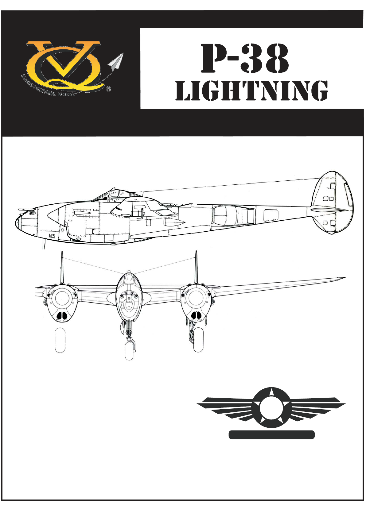
Radio control model
INSTRUCTION MANUAL
Wingspan approx. 83 in.
Fuselage length approx. 57.5 in.
Glow Engine 7.45cc 2T /11.5cc 4T (x2)
Electric Motor 870 Watt Brushless motor x2
Radio 6 Channel / 10 Servos
WARNING! This radio controlled model is NOT a toy. If modified or flown carelessly it could go out of control and
cause serious human injury or property damage. Before flying your airplane, ensure the air field is spacious enough.
Always fly it outdoors in safe areas and seek professional advice if you are unexperienced.
LEGEND MODELS
L
Page 2
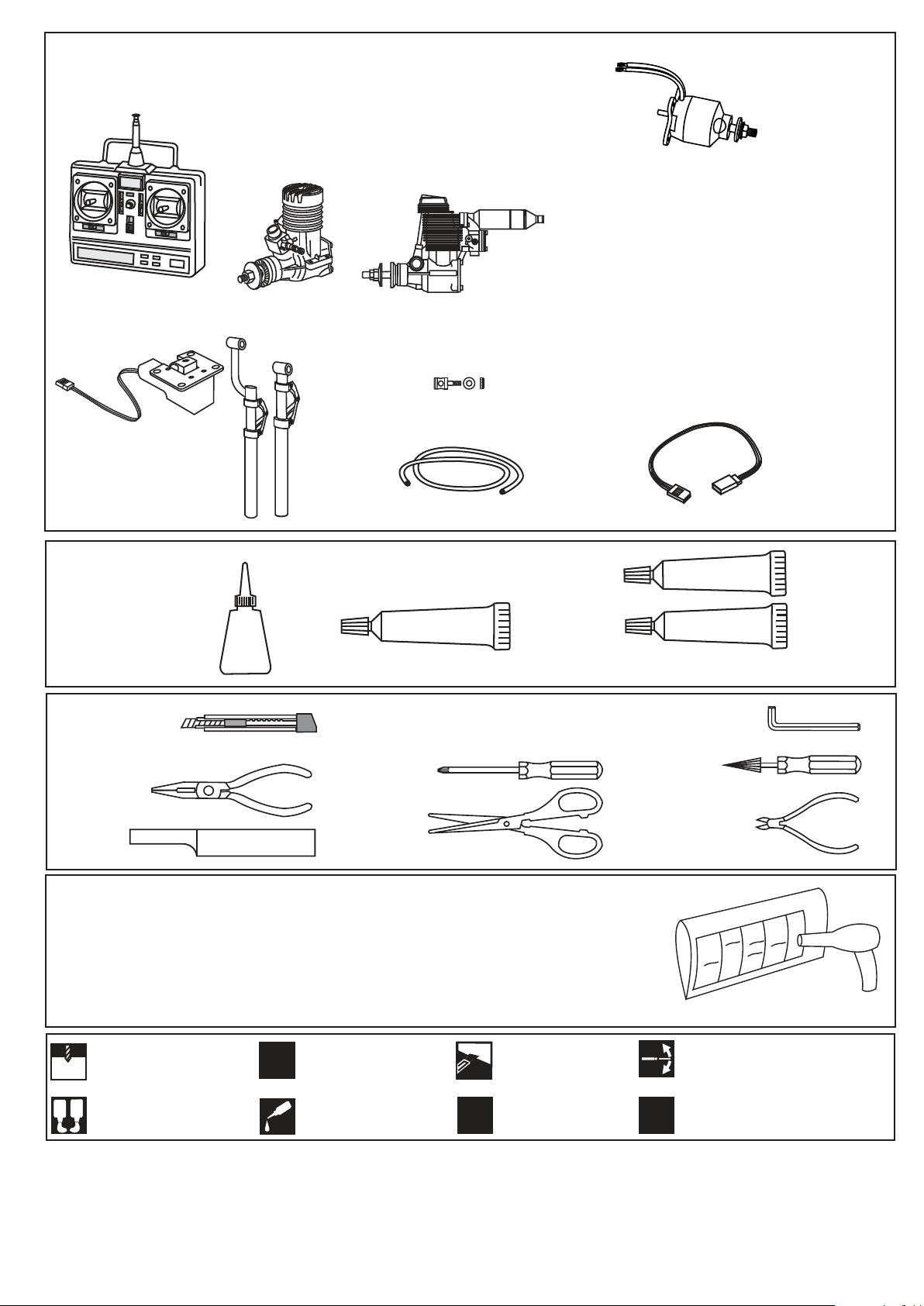
REQUIRED ITEMS
Minimum 6 channel radio
for airplane / 8-10 servos.
Electric Retract:
VQ-ARE18S
Nose gear Eretract&Strut
Main gear Eretract&Struts
.46 - .50 cu.in.(x2)
7.45cc (x2)
.60 - .70 cu.in (x2)
10cc - 11.5cc (x2)
Connector
Silicone tube
Electric Set up 1:
2X Dualsky XM5050EA-7 610Kv motors.
2X Dualsky XC8018BA 80A ESC, 100A burst
2X Dualsky XP45004EX 4S, 35C, 4500mAh Lipo
2X Prop: 14x9 x3-blade Master Airscrew
Approx Weight: 1600grams / 3.6lbs
Electric Setup 2:
2X Dualsky XM5060EA-6 470Kv motors.
2X Castle Creations Edge 100AMP ESC
2X Dualsky XP45005EX 5S, 35C, 4500mAh Lipo
2X Prop: 16x10 x3-blade Master Airscrew
Approx Weight: 2200grams / 4.8 lbs
Extension cord
GLUE
Cyanoacrylate Glue
CA
Hobby knife
Needle nose Pliers
.........................................................
.........................................................
.........................................................
.........................................................
Sander
.........................................................
.........................................................
.........................................................
.........................................................
.........................................................
.........................................................
.........................................................
If exposed to direct sunlight and / or heat, wrinkles can appear. Storing the model in
a coll place will let the wrinkles disappear. Otherwise, remove wrinkles in covering
film with a hairdryer, starting with low temperature. You can fix the corners by using
a hot iron.
SILICON
Silicon Glue
Phillip screw driver
Scissors
EPOXY A
EPOXY B
Epoxy ( 5min-Typ)
Hex Wrench
Awl
Wire Cutters
Drill holes using the stated
1.5mm
size of drill
(in this case 1.5 mm Ø)
A
B
Use epoxy glue
Take particular care here
!
Apply cyano glue
CA
Hatched-in areas:
remove covering
film carefully
Assemble left and right
L/R
sides the same way.
Check during assembly that these
parts move freely, without binding
Not included.
These parts must be
X
purchased separately
Read through the manual before you begin, so you will have an overall idea of what to do.
CONVERSION TABLE
1.0mm = 3/64”
1.5mm = 1/16”
2.0mm = 5/64”
2.5mm = 3/32”
3.0mm = 1/8”
4.0mm = 5/32”
5.0mm = 13/64”
6.0mm = 15/64”
10mm = 13/32”
12mm = 15/32”
15mm = 19/32”
20mm = 51/64”
25mm = 1”
30mm = 1-3/16”
45mm = 1-51/64”
Page 3
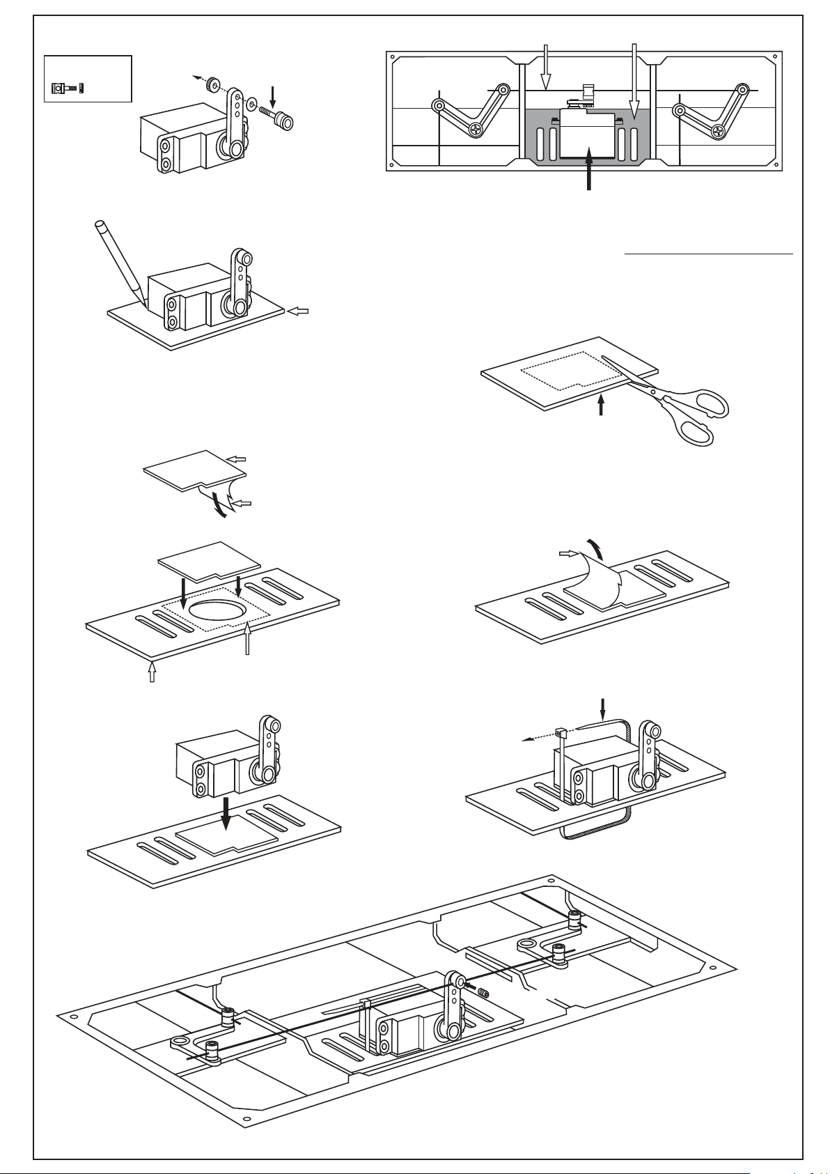
1-Wing
Flap push rod
Servo mount
Connector
........2
1C
Remove the servo out of the wing.
Place the servo onto the adhesive tap as shown.
With the pencil, trace around the servo, where it
meets the adhesive tape.
1E
Connector (included)
1A
Install the push rod connector onto the
outer-most hole of the flap servo arm.
Adhesive tape
1B
-Turn the center wing over.
-Turn the four screws and move the hatch out of the wing.
-Place the flap servo onto the servo mount with the flap push rod installed
as shown.
-Using the pencil, trace around the servo, where it meets the servo mount.
Adhesive tape
(included)
Flap servo
Adhesive tape
1D
With the scissors, cut along the pencil line
1F
Servo mount
1H
Peel the bottom cover
1G
Peel the top cover
Pencil line.
Nylon cable tie
(included)
1I
3mm screw
Move the flap servo arm a few times to make sure it move
freely with out any binding.
Do the same way with the flaps on the left and the right wing
Page 4
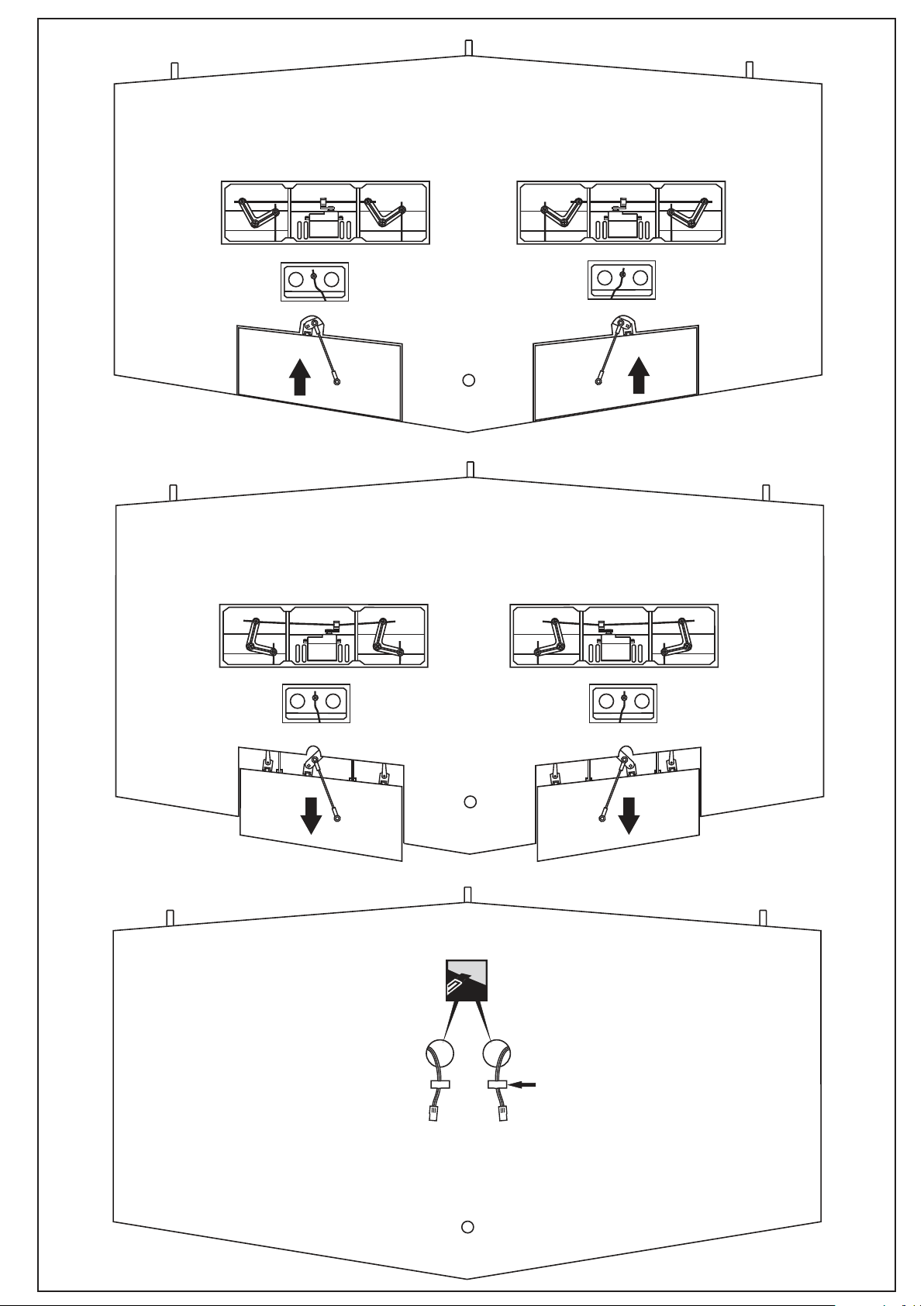
2-Wing
Note: Do not close the hatches in this time
CENTER WING
Bottom-view
The center wing with the flaps in closed position.
The center wing with the flaps in opened position.
Cut away the covering for
the extension cord exit
Adhesive tape (keep the
extension in place)
CENTER WING - Top-view
Page 5
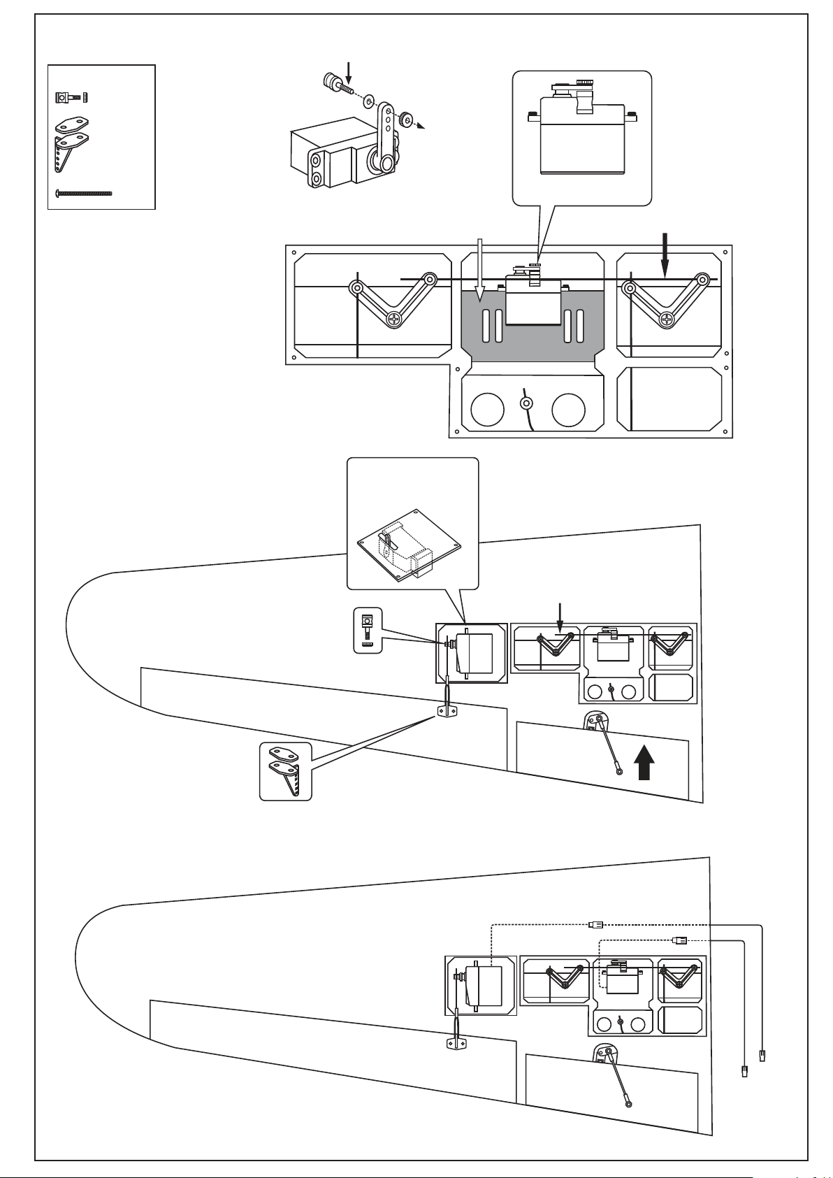
3-Wing
Connector
........2
.............2
2x30mm screw
From Step 3B to Step 3I, follow the
procedure as described in the
1-WING section
.......4
3A
Note: the connector is
turn-down
Connector
Servo mount
Note: the connector is
turn-down
Flap push rod
To be connected the extension with the aileron
servo cord before attach the hatch to the wing
Note: the aileron extension must 700mm long
or use two 300mm long.
3K
Aileron servo hatch with
servo installed (standard
servo using)
3J
Flap pushrod
RIGHT WING - Bottom-view
Note: Do the same way with the Left wing
700mm
extension
RIGHT WING - Bottom-view
Page 6
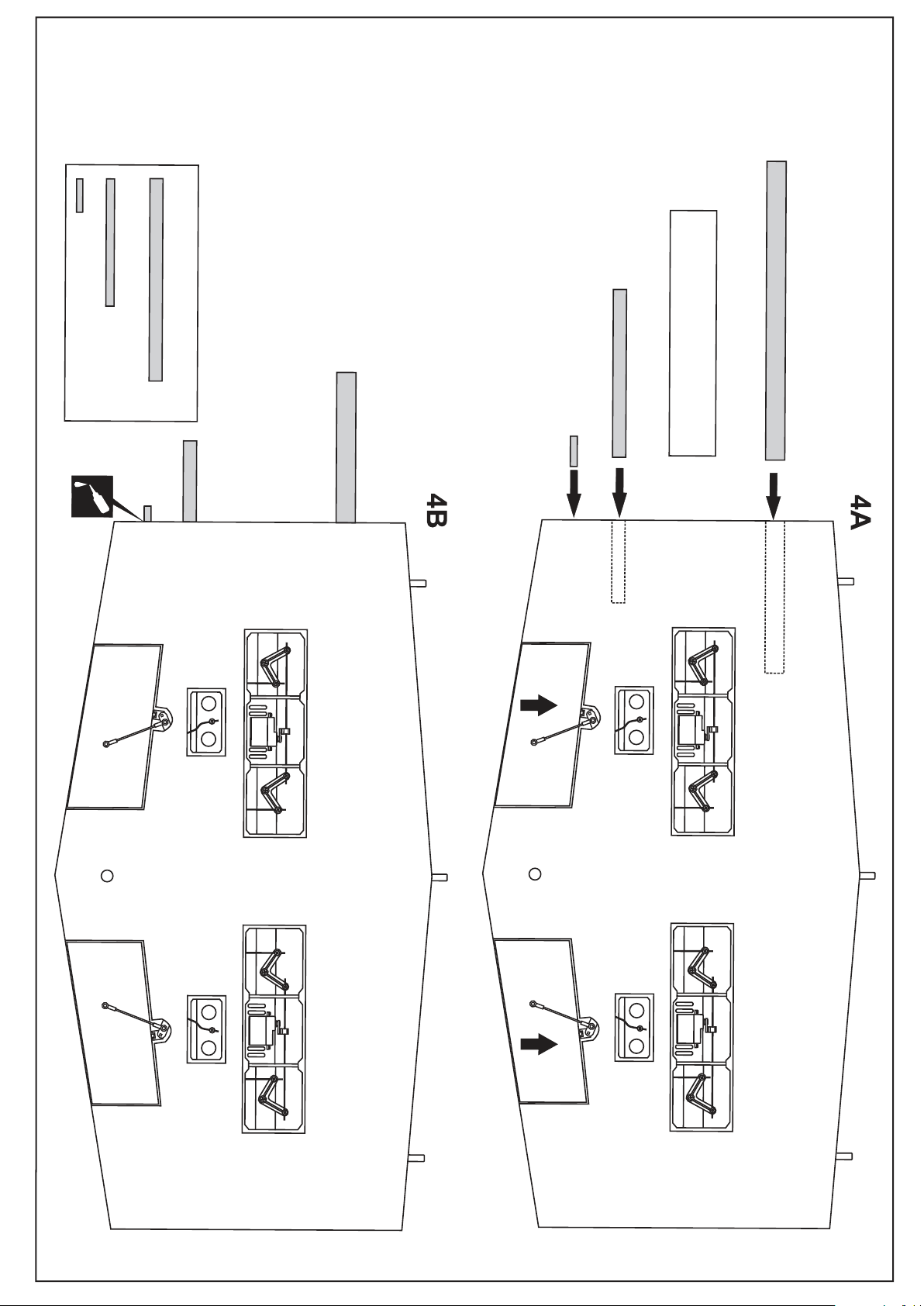
4-Wing
12x182mm aluminum tube
6x12mm wooden dowel
19x317mm aluminum tube
side of the center wing.
Slide the aluminum tube into the left and right
of the center wing.
Do the same way with the other side
......................2
......................2
...2
Glue the dowel only
CA
12x182mm aluminum tube
6x12mm wooden dowel
19x317mm aluminum tube
CENTER WING
Bottom-view
CENTER WING
Bottom-view
Page 7
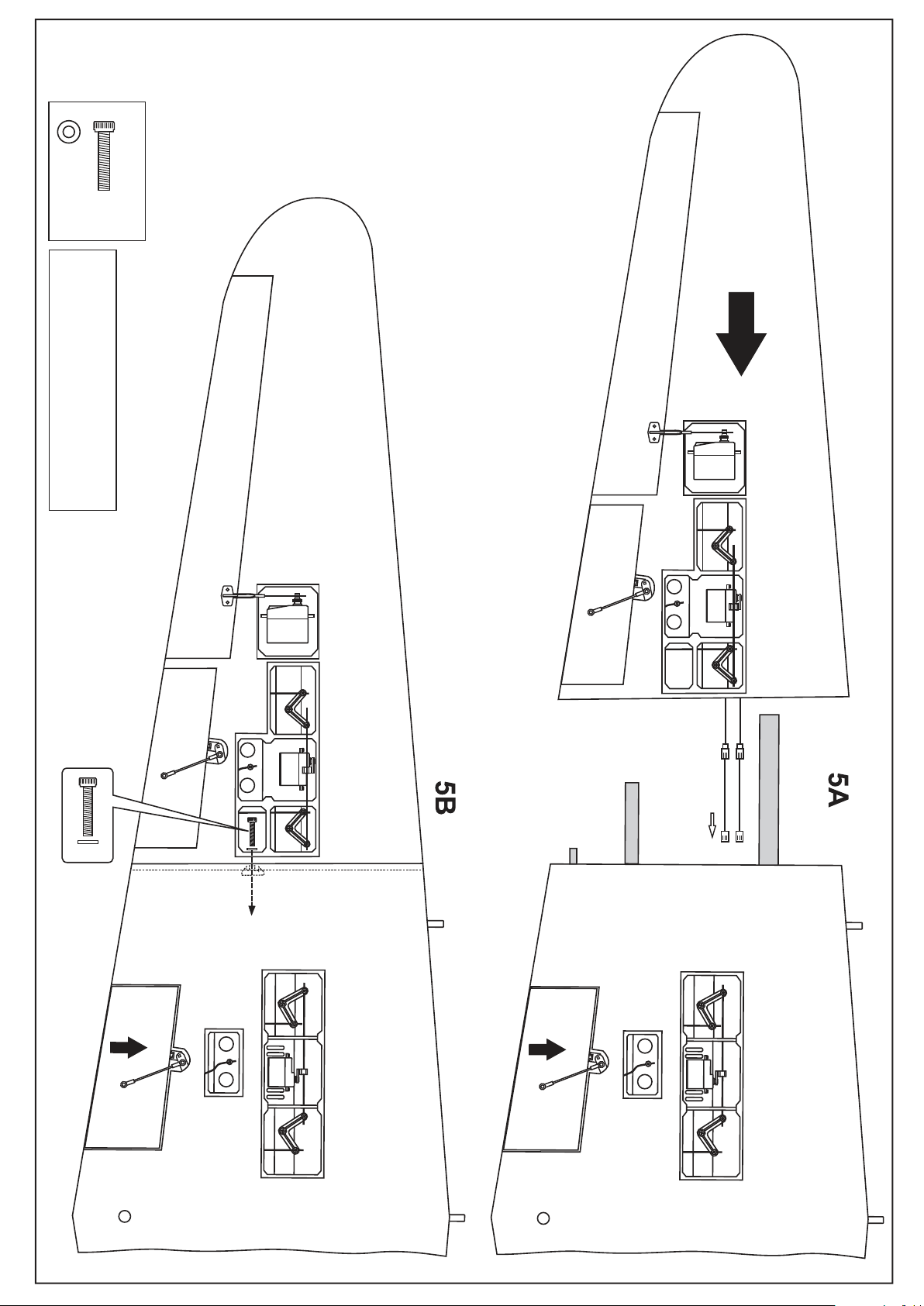
5-Wing
4x20mm screw
.............2
.....2
!Check the ailerons and flaps functions
move in the correct before attach all
hatches to the bottom of the wing.
Carefully, slide the left wing
to meet the center wing
Secure the outer wing in place
using 4x20mm screw
4x20mm screw
Aileron extension
Page 8
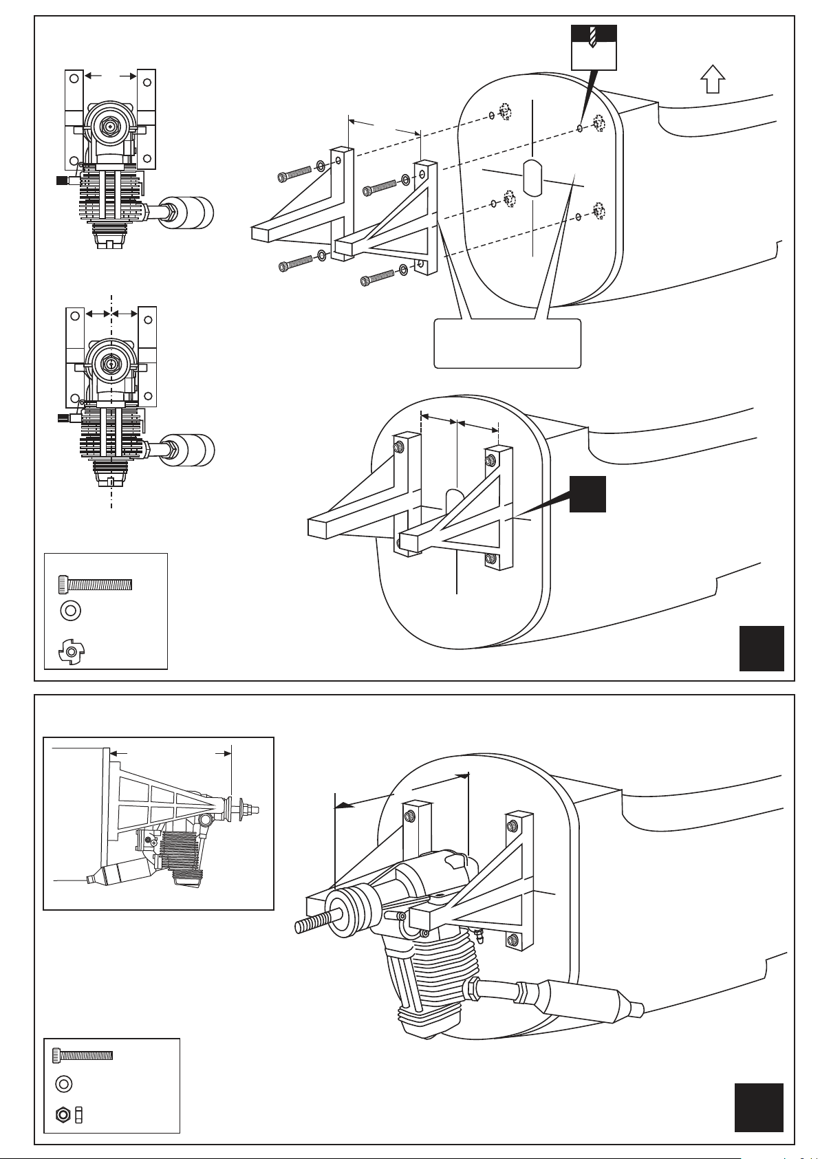
6-Engine mounts
A
A
5.5mm
TOP
B=B’
B
B’
4x30mm screw
.............8
Blind-nut
................8
..8
! Engine thrust on balk head
is already adjust at factory
Align the mark on both
mounts with the center
mark on the balk head.
B
B’
6A
Align the mark on both
mounts with the center
!
mark on the balk head.
6B
BOTTOM
L/R
7-Engine
132~134mm
SIDE-VIEW
Secure the engine to the engine
mount using four 3x25mm screws
Insert the Z-bend into the hole on the throttle
lever of engine.
Note: It may be easier to temporarily remove
the control arm from the carburetor to insert the
Z- bend
3x25...(8)
Washer....(8)
Nut 3mm..(8)
C= 132 ~ 134mm
C
L/R
Page 9
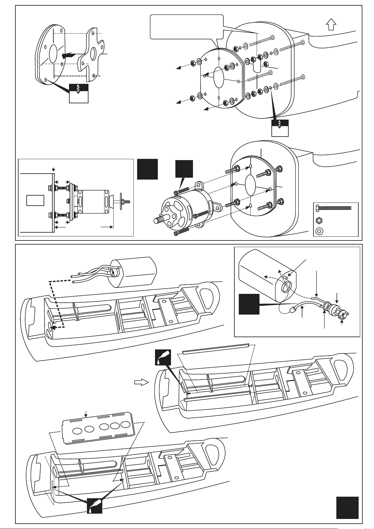
8-Electric Motor
Align the mark on the motor
mounting plate with the
center mark on the balk head.
8A
3mm
Using a aluminum motor mounting plate as a template,
mark the plywood motor mounting plate where the four
holes are to be drilled.
Remove the aluminum motor mounting plate and drill a 1/8”(3mm) hole through the
plywood at each of the four marks marked .
Note: The aluminum motor mounting included with electric motor set.
8B
TOP
BOTTOM
5mm
Firewall
B
B=B’
B’
132~134mm
9-Fuel tank
SIDE-VIEW
9B
FUSELAGE - Top view
L/R
CA
X
8C
FDP
9A
X
9C
5x70mm..8
5mm nut..24
washer...32
To muffler
Filler tube
Rubber
stopper
To engine
Aluminum stopper
(In case of electric motor using)
Aluminum
cap
Installing the Lipo Battery Stand
Lipo Battery stand
9D
CA
FDP
FUSELAGE - Top view
L/R
Page 10
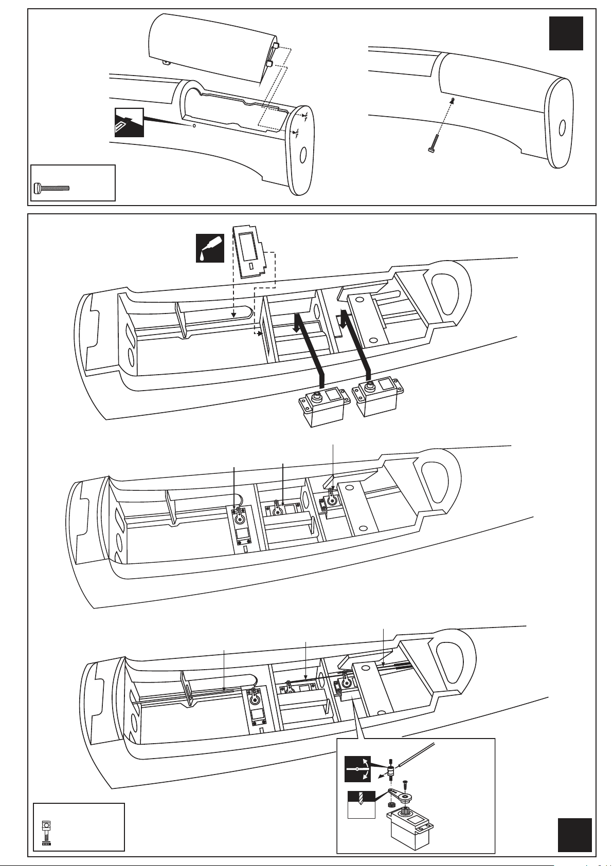
10-Hatch
Cut away only
the covering
Bottom hatch
L/R
Bottom hatch
30x4mm nylon bolt
............4
FUSELAGE - Bottom view
11-Servos
RIGHT FUSELAGE - Top view
11A
CA
Throttle servo
Throttle servo tray
Elevator servo
Elevator servo
Secure the Bottom hatch in place
using the 30x4mm nylon bolt.
Note: Turn the throttle servo tray for
other engine if needed.
Rudder servo
Rudder servo
11B
11C
Connecting rod
...............6
RIGHT FUSELAGE - Top view
Rudder Pushrod
Elevator Pushrod
Throttle pushrod
Rudder pushrod
2 mm
L/R
Page 11
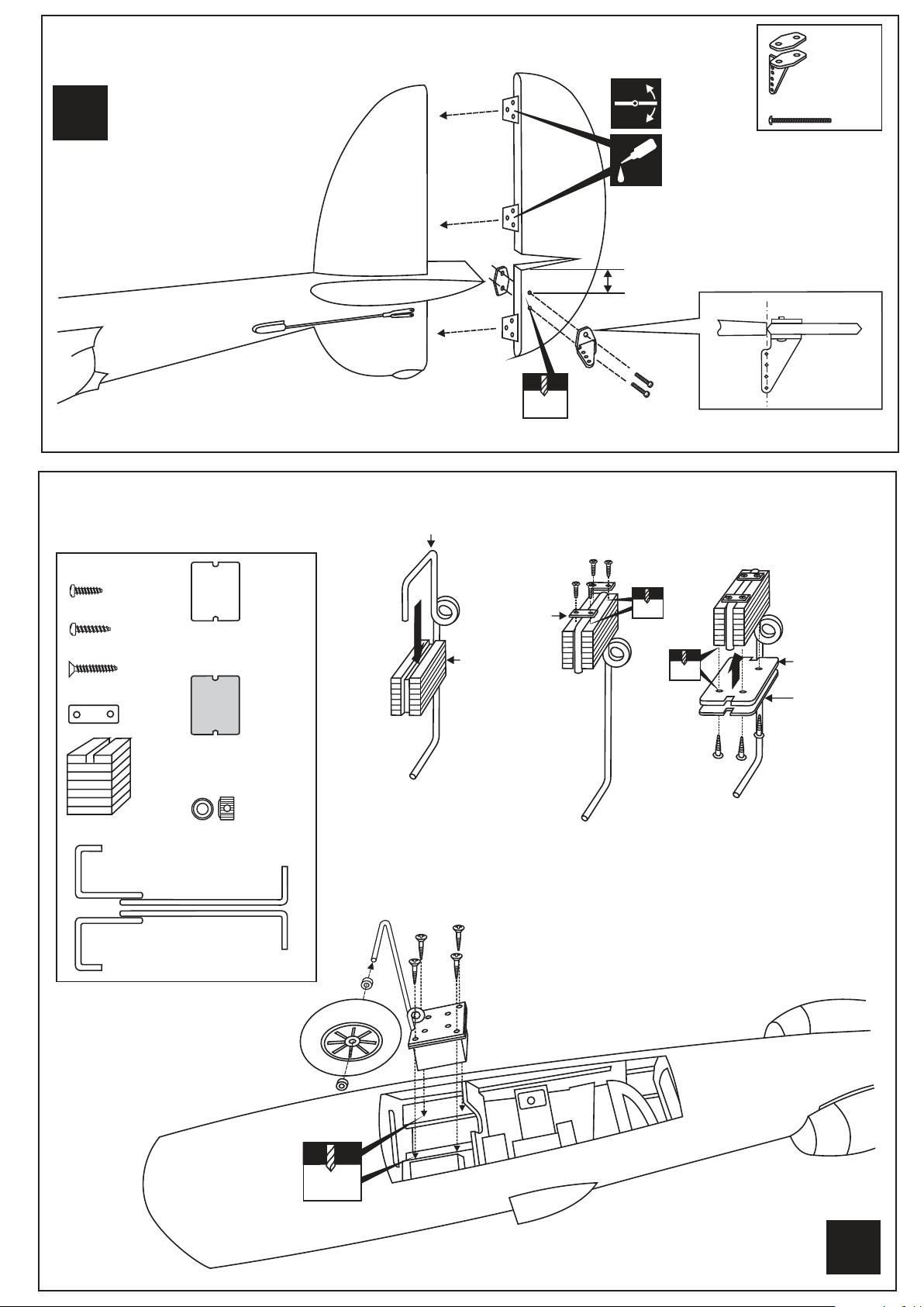
12-Rudder
.............2
L/R
13-Fixed gear
Main landing gear
2 mm
CA
15mm
2x30mm screw
.......4
3x12mm screw
..........8
3x15mm screw
..........8
3x20mm screw
......16
Nylon gear strap
.......4
Gear mount x 2
Main landing gear
Square plastic x 2
Ply gear mount
plate x 2
.........4
4.7mm collar
13A
3x20mm screw
Nylon gear
strap
Gear mount
3x12m
2mm
13B
2mm
3x15mm
Ply gear
mount flat
Square
plastic
13C
2mm
13D
L/R
Page 12
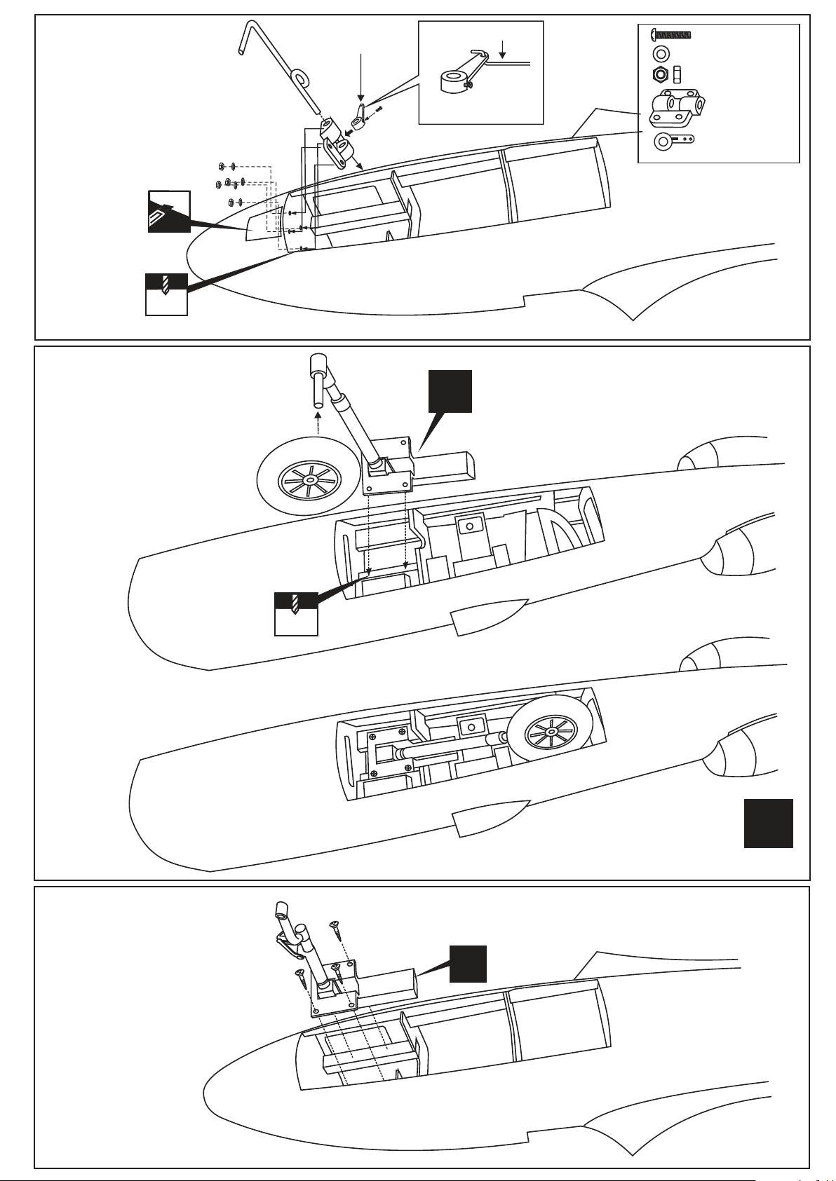
14-Nose gear
Cut the opening
3mm
15-Main gear
(Electric retract)
4.7mm nose gear
Nose gear arm
Nose gear push rod
Nose gear control
arm
Nose gear base (plastic)
MAIN FUSELAGE - Bottom view
Must be purchased separately
X
3x20mm...4
Washer.....4
Nut 3mm...4
Nose gear mount
Nose gear arm
16-Nose gear
(Electric retract)
?
FUSELAGE - Bottom view
L/R
X
Page 13
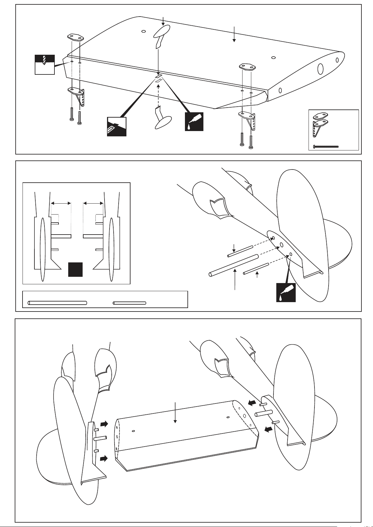
17-Horizontal Stabilizer
2 mm
ABS “balance”
HORIZONTAL STABILIZER
Top-view
Cut away onlly the covering
18-Horizontal Stabilizer
LEFT FUSE.
B=60mm
A=8mm
A
B
A
L/R
12x108mm aluminum tube
RIGHT FUSE.
B=60mm
A=8mm
A
B
A
6x60mm wooden dowel
....2
CA
ABS “balance”
Secure the aluminum
tube and wooden dowel
in place using Thin CA glue
................4
6x60mm
Wooden dowel
Wooden dowel
Aluminum tube
12x108mm
6x60mm
CA
.............2
2x30mm screw
.......4
19-Horizontal Stabilizer
LEFT FUSELAGE
RIGHT FUSELAGE
Horizontal stabilizer
Page 14
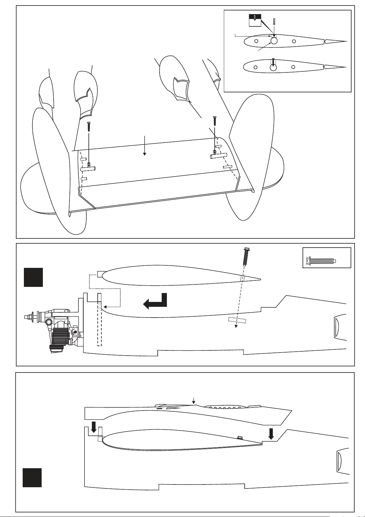
20-Horizontal Stabilizer
20A
Balsa block
2.mm
TOP
2.mm drill bit
Drill through both the balsa
block and aluminum tube
Horizontal stabilizer
3x15mm screw
Aluminum tube
3x15mm screw
20B
Note: The holes on the bottom of the Horizontal stabilizer
are pre-drilled at factory
3x15mm screw
21-Installing the wing
L/R
RIGHT / LEFT FUSELAGE (TAIL BOOM)
22-Installing the wing shield
TOP
WING
RIGHT / LEFT WING SHIELD
6x40 Nylon bolt
6x40 Nylon bolt
.....4
Trial fit the fuselage-top
shield onto the wing, If
necessary, sand the
edge of the fuselage-top
shield until this is
achieved.
L/R
WING
RIGHT / LEFT FUSELAGE (TAIL BOOM)
Secure the wing shield in place using 2.2x12mm screws
Page 15
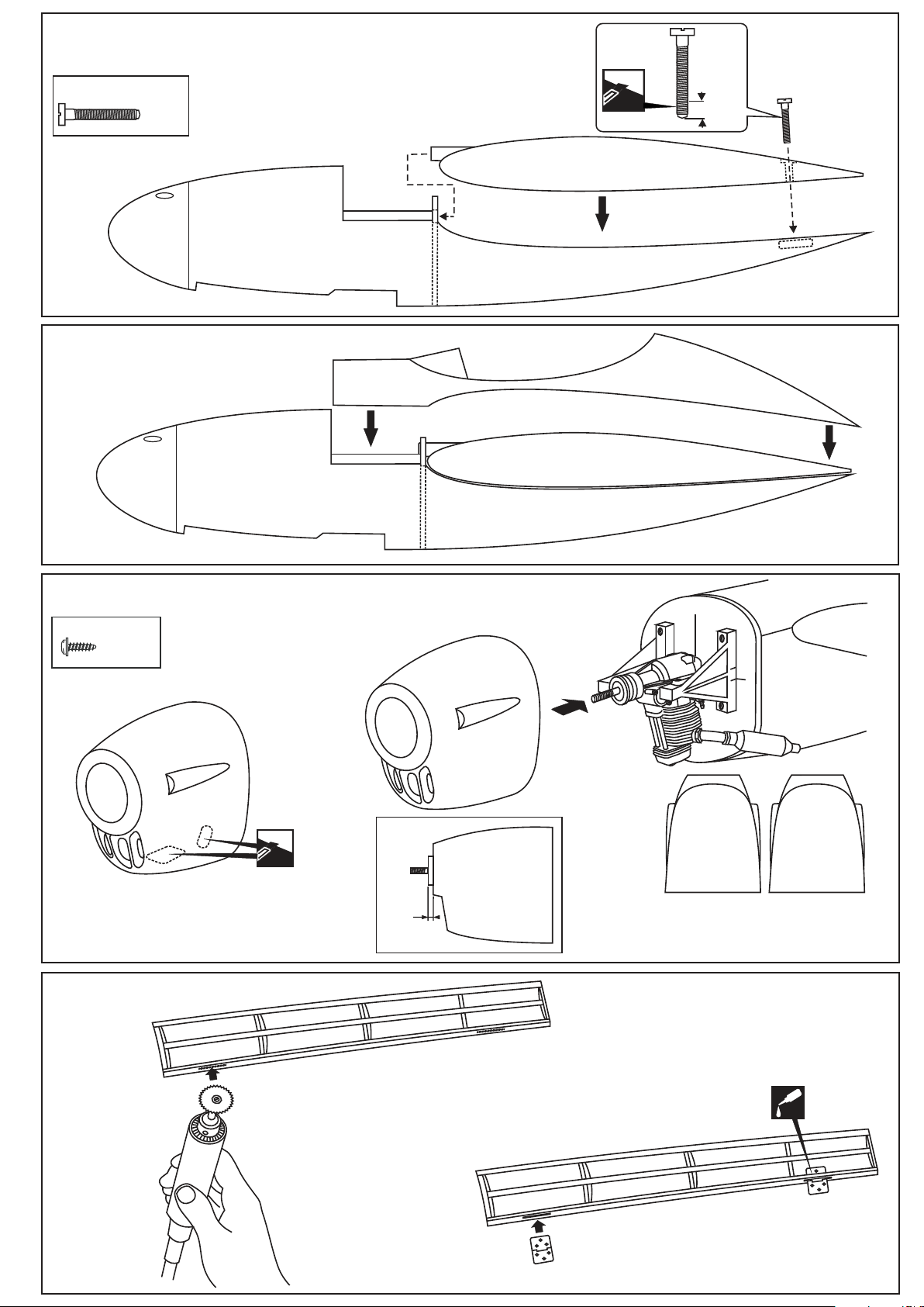
23-Installing the main fuselage
6x50mm plastic bolt
....1
10mm
WING
FIBER GLASS MAIN FUSELAGE
24-Installing the cockpit
Secure the cockpit in place
using 2x8mm screws
25-Cowling
2.5x12mm screw
...........8
Secure the cowl in place using
2.5x12mm screws
FIBER GLASS
COCKPIT
FIBER GLASS MAIN FUSELAGE
26-Gear door
26A
2mm
Gear door
Hinge
COWL
BOTTOM VIEW
L R
Note: The “L” Cowl for LEFT fuselage and
“R” Cowl for RIGHT fuselage (looking from
REAR to FRONT and TOP view).
COWL
BOTTOM VIEW
CA
26B
Page 16
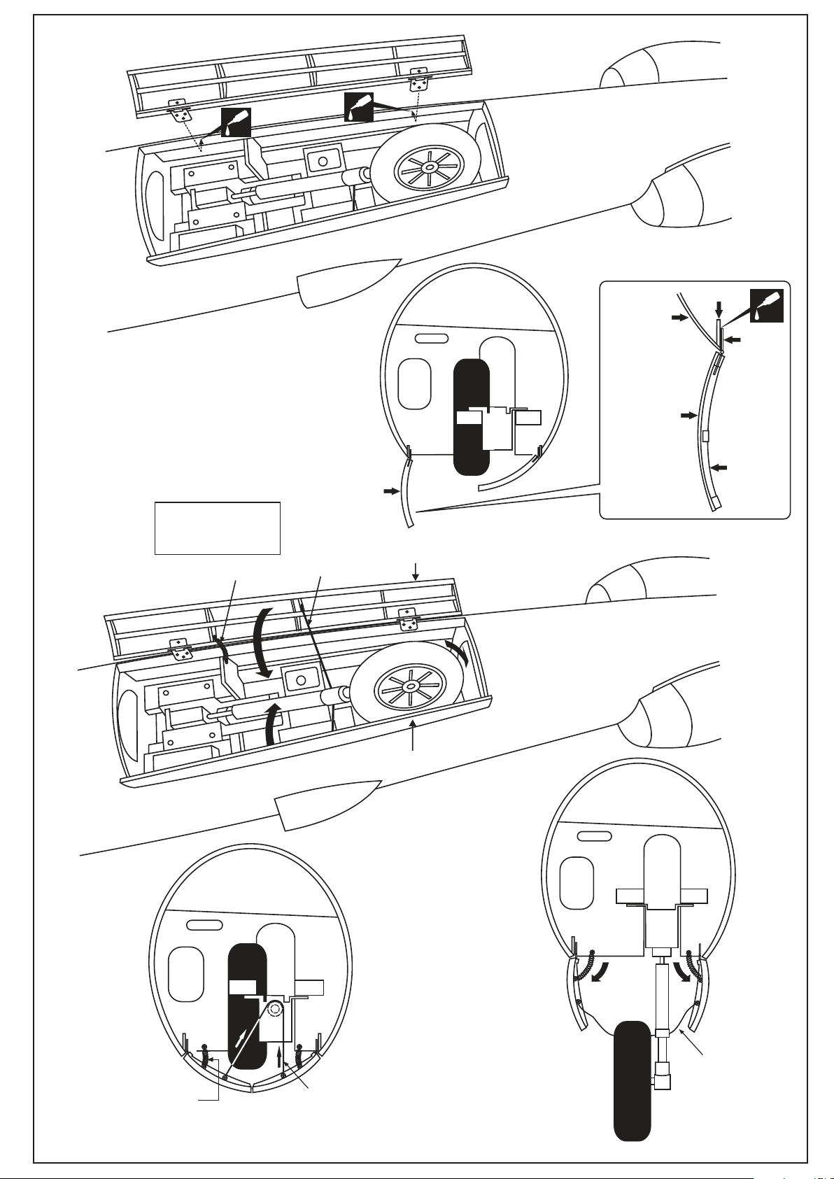
27-Gear door
27A
CA
CA
Fuselage
Fuselage
Gear door
Frame
CA
Hinge
27B
Note: you can find the
same spring in old
ball-point pen
Spring (not include)
Gear door
Cotton thread
(not include)
Gear door
Gear door
GEAR DOOR
IN OPENED
POSITION
Fuselage
Frame
Fuselage
Spring (not include)
ALL GEAR DOORS
IN CLOSED POSITION
(RETRACT LANDING GEAR IN RETRACTED POSITION)
Cotton thread
(not include)
Cotton thread
(not include)
ALL GEAR DOORS
IN OPENED POSITION
(RETRACT LANDING GEAR IN EXTENDED POSITION)
Page 17
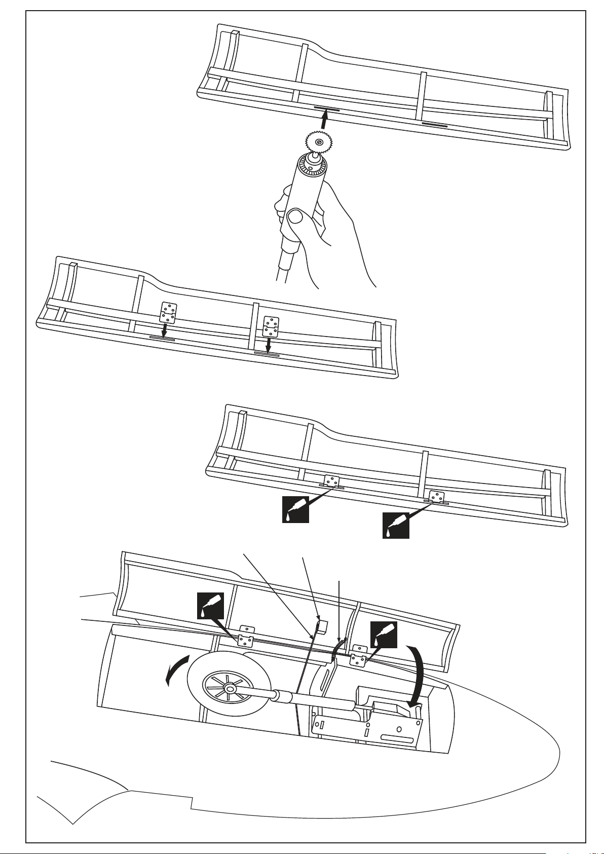
28-Gear door
Gear door
(main fuselage)
28A
28C
Cotton thread
(not include)
CA
CA
Balsa block
(not include)
Spring (not include)
CA
28B
CA
Gear door
Bottom-view
28D
Page 18
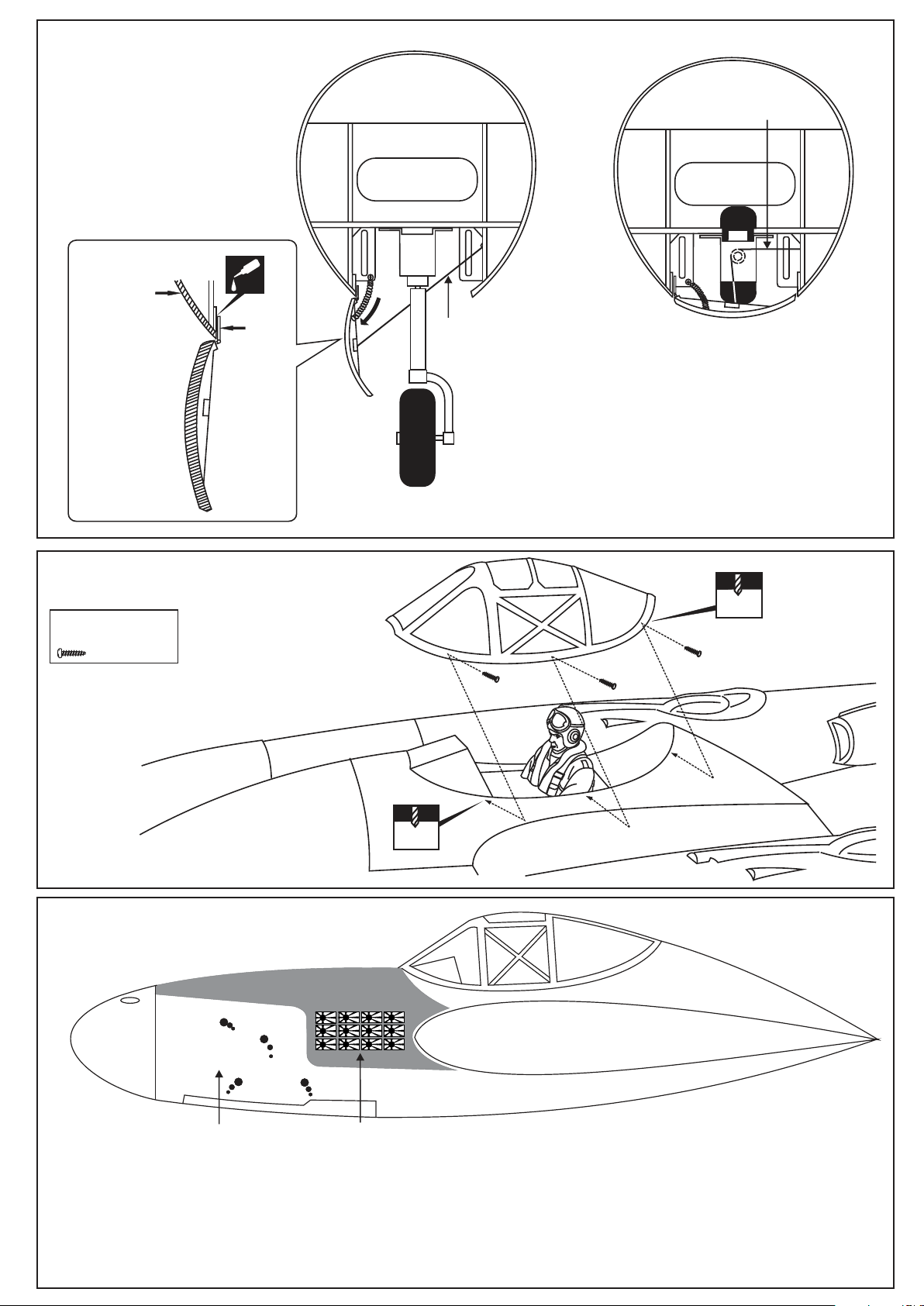
29-Gear door
Cotton thread
Fuselage
side
GEAR DOOR
IN OPENED
POSITION
30-Canopy
2x8mm screw
...................6
CA
Hinge
Gear door
Cotton thread
(not include)
GEAR DOOR IN OPENED
POSITION
GEAR DOOR IN CLOSED POSITION
(NOSE RETRACT LANDING GEAR
IN RETRACTED POSITION)
(RETRACT LANDING GEAR IN
EXTENDED POSITION)
1.2mm
2x8mm screw
1.2mm
31-Decal
T
T
T
T
U
U
P
P
“Putt Maru” decal is
only for one side
Note: Cut out the stickers and apply them in the proper area. Do not peel the backing paper off all at once.
Peel off one corner of the backing and cut off with scissors. Arrange sticker on model and when satisfied adhere the corner without
backing.
Carefully peel back the rest of the backing while at the same time adhering the rest of the sticker.
Try not to make air bubbles, if there are some, carefully puncture sticker (center of bubble) but not model surface with the tip of the knife
or sharp pin and
squeeze out the air. At curves stretch sticker and apply a little heat so that no ceases occur. Cut off the excess that is produced.
P
P
U
U
T
T
M
M
T
T
A
A
R
R
U
U
Kill-mark only
for one side
Putt Putt Maru version
Page 19
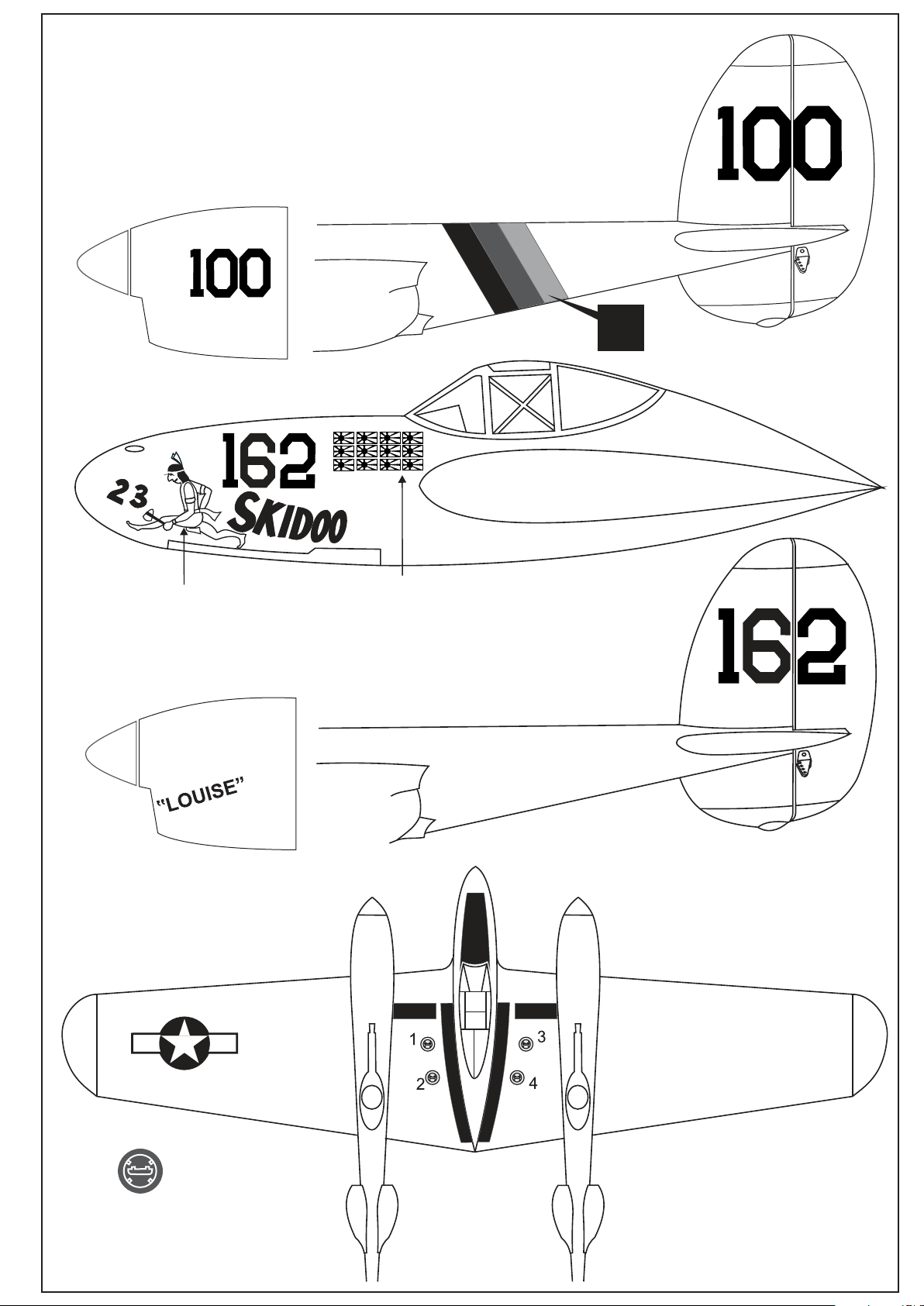
32-Decal
IMPORTANT:
Please do not clean your model with pure alcohol, gasoline or strong sloven, only use
kerosene or liquid soap with water or use glass cleaner to clean on surface of your model
to keep the colour not fade.
L/R
“Skidoo”decal is
only for one side
Kill-mark only
for one side
Skidoo version
1,2,3,4
Fuel cap sticker (for all versions)
Page 20
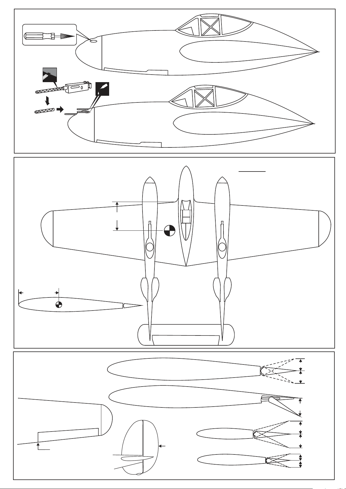
33-Installing the guns
CA
34-Balance
115~120mm
WING ROOT
The ideal C.G. position is 115 ~ 120mm
behind the leading edge.
115 ~ 120mm
WARNING:
Never fly before checking
the Cg’s required position.
35-Control ranges
Position for right diagram.
AILERON
FLAP
Position for
right diagram.
RUDDER
ELEVATOR
8~10mm
8~10mm
30~35mm
25~30mm
25~30mm
10~12mm
10~12mm
 Loading...