

Page 1
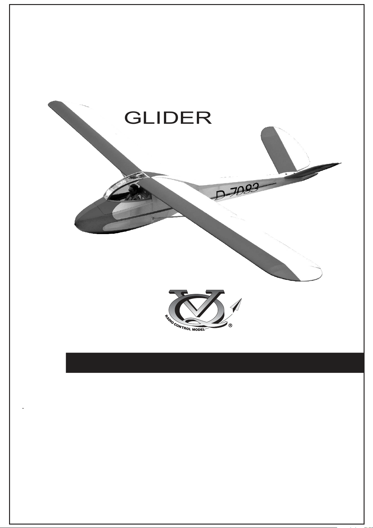
Radio control model • R/CFlugmodell
KA-3
GLIDER
ARF BY
ALL BALSA, PLYWOOD CONSTRUCTION AND ALMOST READY TO FLY
Instruction manual / Montageanleitung
TECHNISCHE DATEN
Spannweite 3.050mm
Lange 1.675mm
Fernsteuerung 5-7 Kanal / 4-5 Servos
WARNING! This radio controlled model is NOT a toy. If modified or flown carelessly it could go out of controll and
cause serious human injury or property damage. Before flying your airplane, ensure the air field is spacious enough.
Always fly it outdoors in safe areas and seek professional advice if you are unexperienced.
ACHTUNG! Dieses ferngesteuerte Modell ist KEIN Spielzeug! Es ist für fortgeschrittene Modellflugpiloten bestimmt,
die ausreichende Erfahrung im Umgang mit derartigen Modellen besitzen Bei unsachgemäßer Verwendung kann
hoher Personen- und/oder Sachschaden entstehen. Fragen Sie in einem Modellbauverein in Ihrer Nähe um
professionelle Unterstützung, wenn Sie Hilfe im Bau und Betrieb benötigen. Der Zusammenbau dieses Modells ist
durch die vielen Abbildungen selbsterklärend und ist für fortgeschrittene, erfahrene Modellbauer bestimmt.
SPECIFICATIONS
Wingspan 3.050mm
Length 1.675mm
Radio 5-7 Channel / 4-5 Servos
Page 2
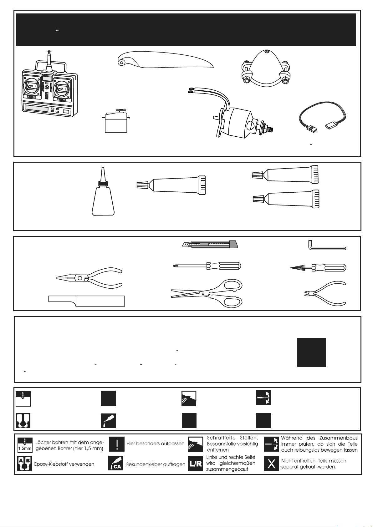
REQUIRED FOR OPERATION (Purchase separately)
BENOTIGTE KOMPONENTEN (Nicht im Lieferumfang enthalten)
Kunststoff-Spinner
(im Antriebsset KA7)
Extension cord
Servoverlangerungskabel
5-7 channel radio
for airplane
5-7 Kanal
Fernsteuerung
Klappluftschraube
(im Antriebsset KA7)
Mini servo S1513
Best.Nr. C1085
Brushless Motor + Regler
(im Antriebsset KA7)
Antriebsset KA7
# C4479
Battery / Flugakku
# C2141 LEMONRC 3700-11.1V
EPOXY A
SILICON
Cyanoacrylate Glue
Sekundenkleber
CA
Silicon Glue
Silikonkleber
Epoxy Glue (30 minutes type)
Epoxy-Klebstoff (30min)
Tool Required/ Erfoderliches Werkzeug
.........................................................
.........................................................
.........................................................
.........................................................
.........................................................
.........................................................
.........................................................
.........................................................
.........................................................
.........................................................
.........................................................
The pre-covered film on ARF kit may wrinkle due to variations of temperature.
Store model in a cool and dry place for awile.
Then, staring with low heat, you may carefully use a hair dryer to smooth out wrinkels.
Die Bespannung des Modells kann durch Temeratureinflusse erschlaffen oder Falten
werfen z.b bei zu starker Sonnenenstrahlung oder Hitze.
Stellen Sie das Modell zunachst an einen kuhlen Platz fur eine bestimmte Zeit. Danach
konnen Sie versuchen die restlichen Falten vorstichtig mit einem Haartrockner zu behandeln.
EPOXY B
!
Drill holes using the stated
1.5mm
size of drill
(in this case 1.5 mm Ø)
A
B
Use epoxy glue
CONVERSION TABLE
1.0mm = 3/64”
1.5mm = 1/16”
2.0mm = 5/64”
2.5mm = 3/32”
3.0mm = 1/8”
4.0mm = 5/32”
5.0mm = 13/64”
6.0mm = 15/64”
Take particular care here
!
Apply cyano glue
CA
10mm = 13/32”
12mm = 15/32”
15mm = 19/32”
20mm = 51/64”
Hatched-in areas:
remove covering
film carefully
Assemble left and right
L/R
sides the same way.
25mm = 1”
30mm = 1-3/16”
45mm = 1-51/64”
Check during assembly that these
parts move freely, without binding
Not included.
These parts must be
X
purchased separately
Page 3
1
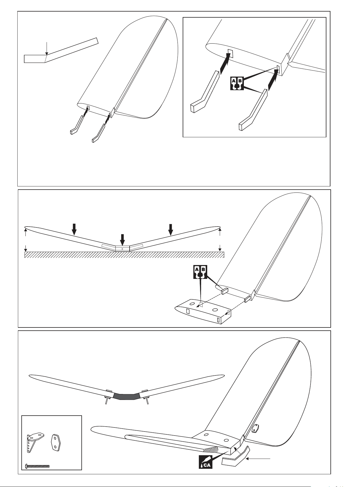
1- Using a pencil, mark the line on the braces.
2- Trial fit the horizontal tail joiner into one of the horizontal tail panel, It should insert smoothly up to the line marked
above. If the fit is over tight, it may be necessary to lightly sand the brace.
3- Remove the brace and coat one half of the brace with 30 minute epoxy up to the line.
4- Install the epoxy-coated side of the brace into the horizontal tail brace cavity up to the line.
5- Do the same way with other horizontal tail.
Line
Front tail brace (G)
Left and Right
Tail brace (S)
Left and Right
2
LEFT HORIZONTAL TAIL PANEL RIGHT HORIZONTAL TAIL PANEL
HORIZONTAL TAIL CENTER
A
A = A’
Carefully slide the horizontal tail panels together,
ensuring that they are accurately aligned. Firmly
press the two horizontal tail panels to the
horizontal tail center, Making sure that the “V” of
dihedral brace is positioned correctly.
A’
Plastic control horn
and back plate
.....2
2x30mm screw
...........4
Control horn
KA3
Control horn
Rear tail brace (Ka3)
Page 4
3
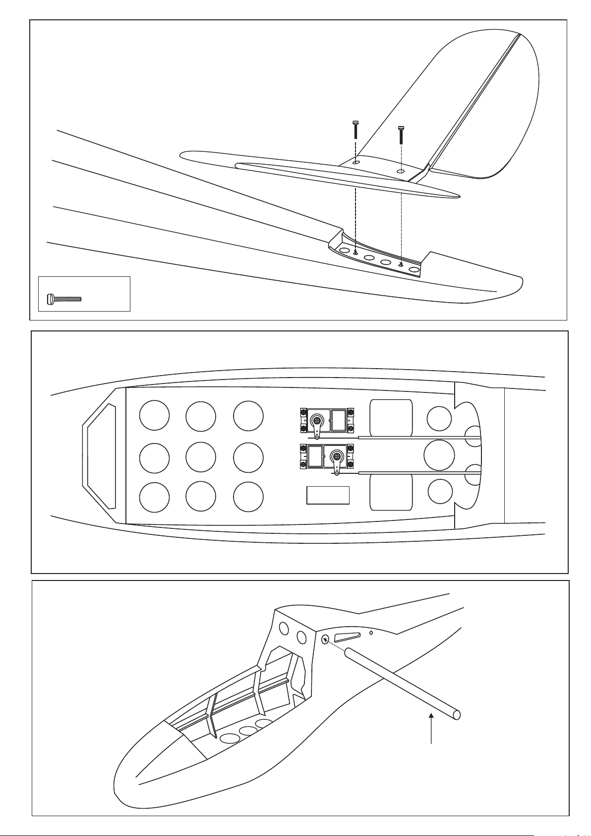
30x4mm nylon bolt
............2
4x30mm
nylon bolt
4
5
Höhenruderservo
Höhenruderservo
FUSELAGE - TOP VIEW / UNTERANSICHT
18x490mm aluminum tube
Page 5
6
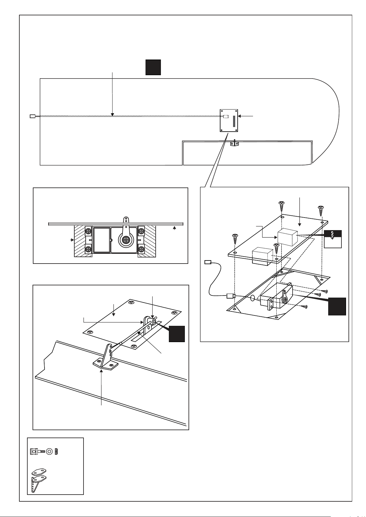
WING - BOTTOM VIEW
UNTERSICHT
Aileron extension cord
Installing the aileron servo on to the hatch
SIDE-VIEW
Servo mount
Seitenansicht
X
Hatch
1
Servo mount
Aileron servo hatch
Aileron servo hatch
2x10mm
1.5mm
2
Aileron servo arm
Aileron control horn
Seitenansicht
Aileron servo hatch
Connector
Aileron push-rod
AILERON
X
X
Aileron servo installation
Connector 2mm
...........2
Plastic control horn
...........2 set
Page 6
7
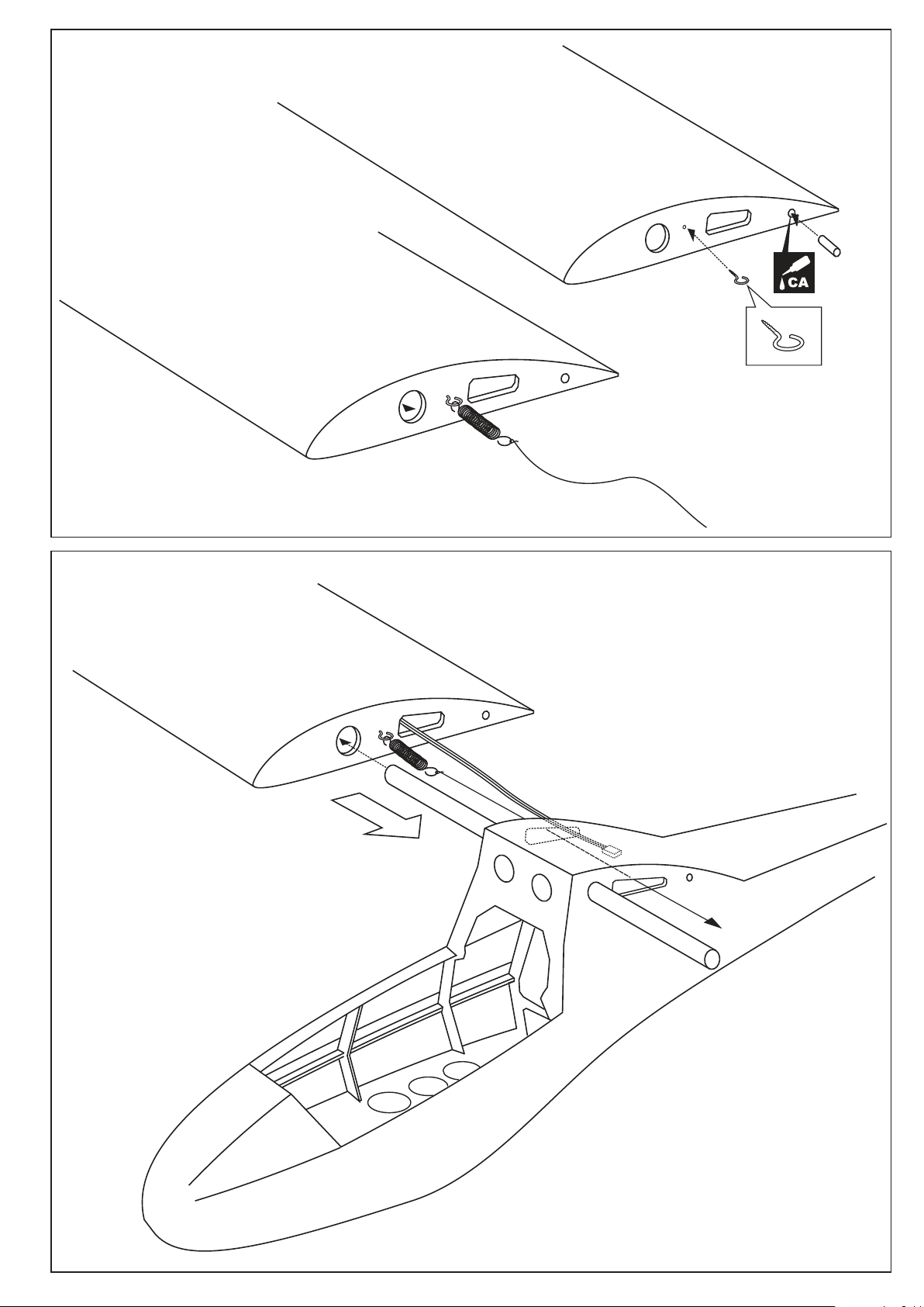
Do the same way with other wing half
Metal hook (x2)
Spring (x1)
8
Aileron & Spoiler extension cord
Page 7
9
10
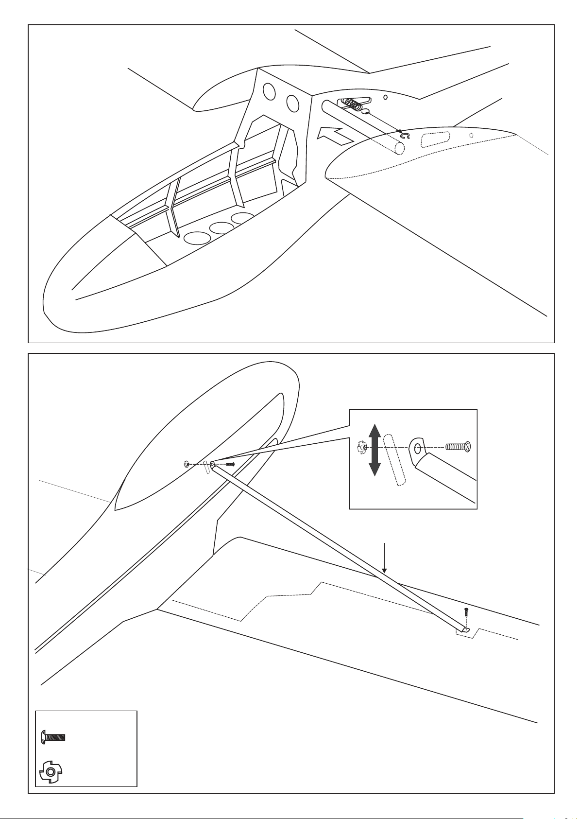
Do the same way with other side
Aluminum wing brace
3x10mm screw
.......................4
3mm blind nut
.......................2
Page 8
11
12
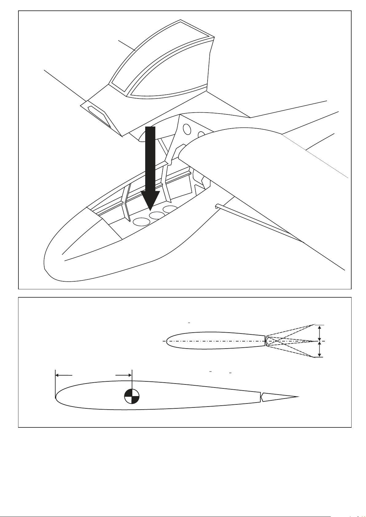
Elevator
Hohenruderausschlag
Uberprufen Sie vor dem Flug den Schwerpunkt.
 Loading...