

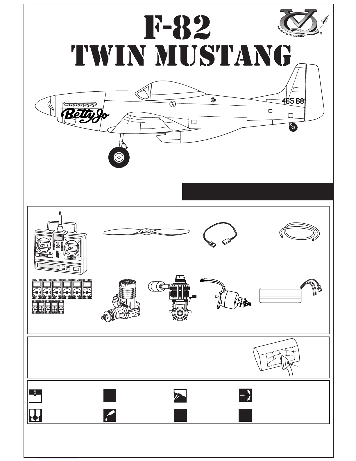
SPECIFICATIONS
Wingspan 2100mm
Length 1240mm
Electric Motor 800 Watt
Glow Engine .46 2-T / .70 4-T
Radio 8 Channels / 11 Servos
WARNING! This radio controlled model is NOT a toy. If modified or flown carelessly it could go out of controll and
cause serious human injury or property damage. Before flying your airplane, ensure the air field is spacious enough.
Always fly it outdoors in safe areas and seek professional advice if you are unexperienced.
Instruction manual
Radio control model
EMERGENCY
Pilot LT Col. BOB THACKER
FLIGHT TEST DIVISION
A.M.C
WRIGHT FIELD DAYT
ON. OHIO
1.5mm
A
B
!
CA
L/R
Assemble left and right
sides the same way.
X
Drill holes using the stated
size of drill
(in this case 1.5 mm Ø)
Use epoxy glue
Take particular care here
Hatched-in areas:
remove covering
film carefully
Not included.
These parts must be
purchased separately
Check during assembly that these
parts move freely, without binding
Apply cyano glue
Low setting
Minimum 8 channels radio
for airplane with 11 servos
(in case of gas engine using)
.60 ~.70 - 4 cycle
10.5x6 for .40 - 2 cycle engine
11x6 for .46 - 2 cycle engine
12x6 for .60 - 4 cycle engine
12x7 for .70 - 4 cycle engine
13x6 for brushless Motor.
Silicone tube
Servo extension:
.46 ~ .50 - 2 cycle
Symbols used throughout this instruction manual, comprise:
700~800 Watt
Brushless Motor.
Li-Po Battery, 14.8V, 4000mAH, 80A
If exposed to direct sunlight and/or heat, wrinkels can appear. Storing the
model in a cool place will let the wrinkles disappear. Otherwise, remove
wrinkles in covering film with a hair dryer, starting with
low temperature. You can fix the corners by using a hot iron.
REQUIRED FOR OPERATION (Purchase separately)
300mm long x3 (ailerons - center flap)
500mm long x2 (Flap)
600mm long x2 (Elevator)
2 mm
1B
CA
CA
Push the wooden dowel to the
hole up to the center line
Thin CA
Thin CA
1A
BOTTOM-VIEW
Main
landing gear
Gear
mount
1C
3x20mm
Nylon gear
strap
2mm
1D
3x20mm
Ply gear
mount flat
Square
plastic
2mm
1E
1-WING
CA
Thin CA
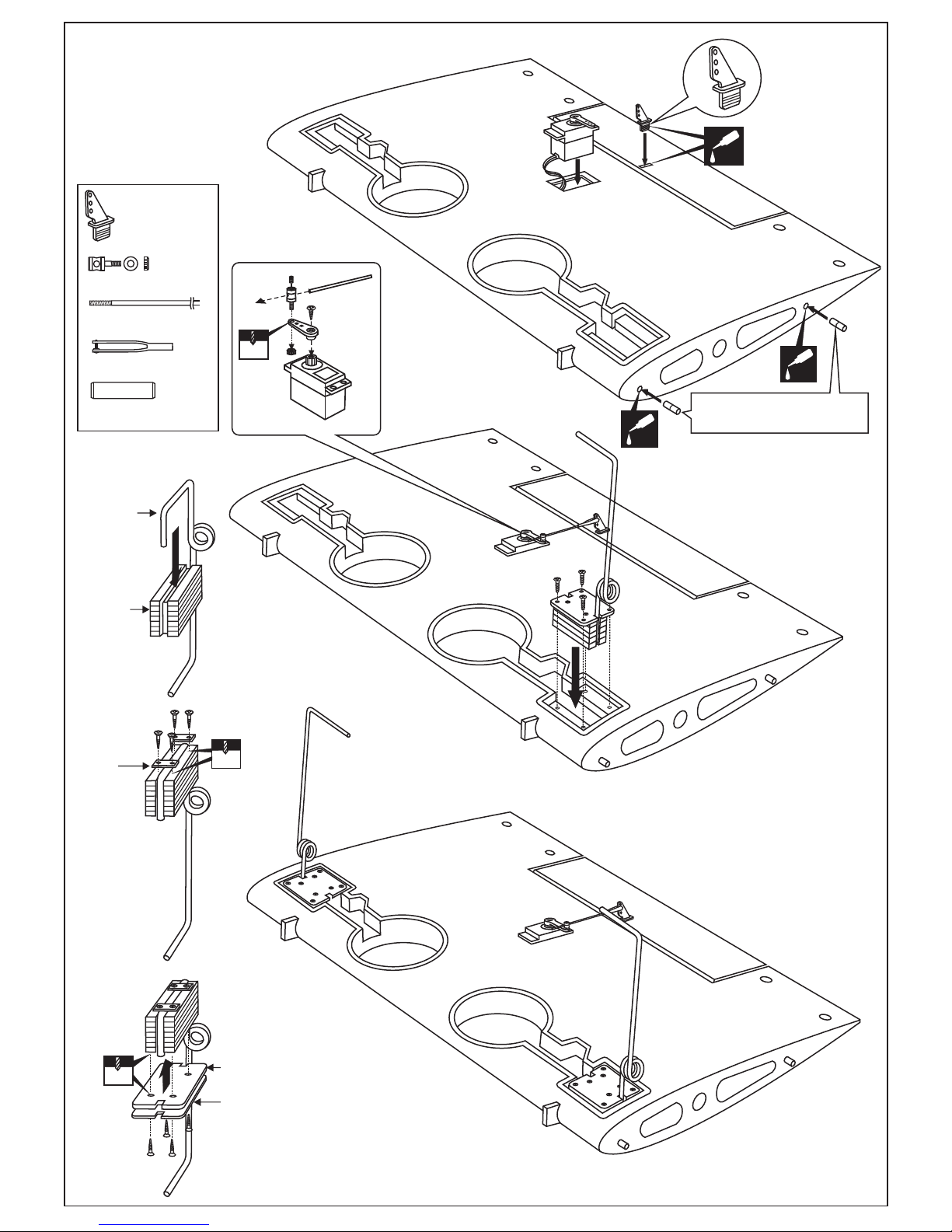
FIXED LANDING GEAR
ASSEMBLY
DO THE SAME WAY WITH
OTHER SIDE
2x170mm rod.......1
Steel clevis...........1
Connector.............1
......................1
Wooden dowel.....4
X
2mm
3x15mm
Ensure smooth
non-binding movement
Ensure smooth
non-binding movement
X
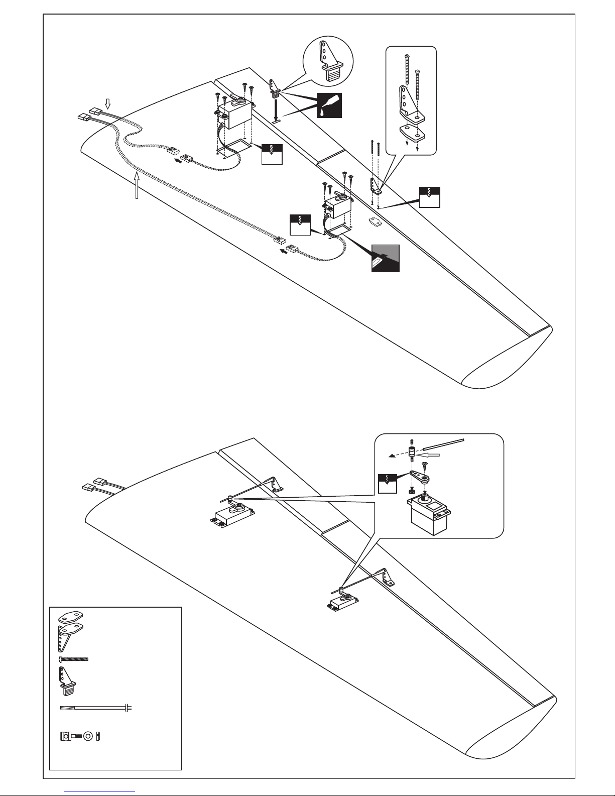
300mm servo
extension (not included)
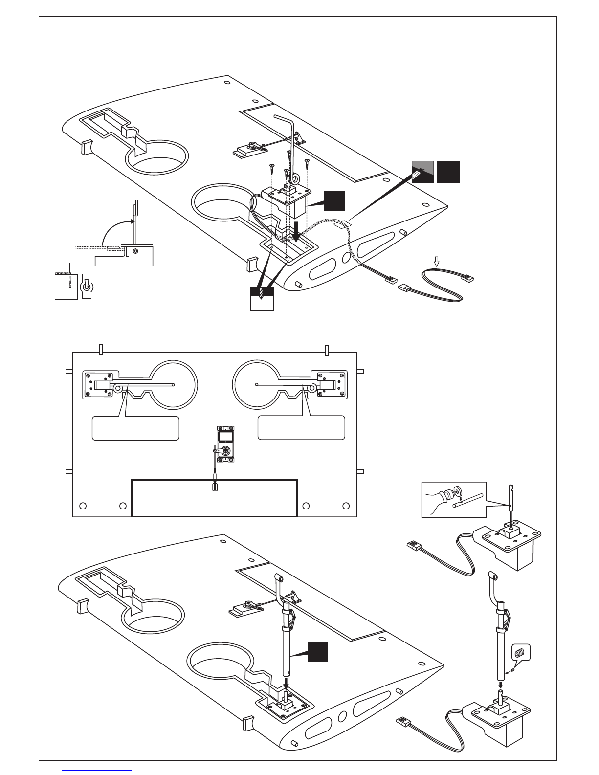
Turn the center wing below, with the hobby knife, cut away
only the covering on the top side of the wing for the electric
retract servo cord exit.
Cut away only
the covering
(on top side)
L/R
CENTER WING - BOTTOM VIEW
ELECTRIC RETRACT
EXTENDED POSITION
RETRACTED
POSITION
ON
OFF
GEAR
SWITCH
RX
Connect the electric retract to receiver, “ON” the
gear switch for the electric retract at extended position
before install the landing gear to the electric retract.
Note: Retract landing gear and Strut not included.
3mm set
screw
In case your E-retracts can not open (to extended position) after closed (retracted position). Please make sure
your E-retract wasn’t stuck when it close. Stuck, this problem maybe from the struts, when E-retract close, the
body of the struts, it touch to the body of E-retract and it make the E-retracts can’t close 100%, or maybe the
wheel touch to the edge of the wing or plastic cover. In this case, after check all the problem above, please use
your finger push the steel wire (or struts in case you use struts) down in the same time you click “ON” the
gear switch on your transmitter.
When the E-retract open (extended position), please solve the problem to
make sure it always close and open in flight.
Note:
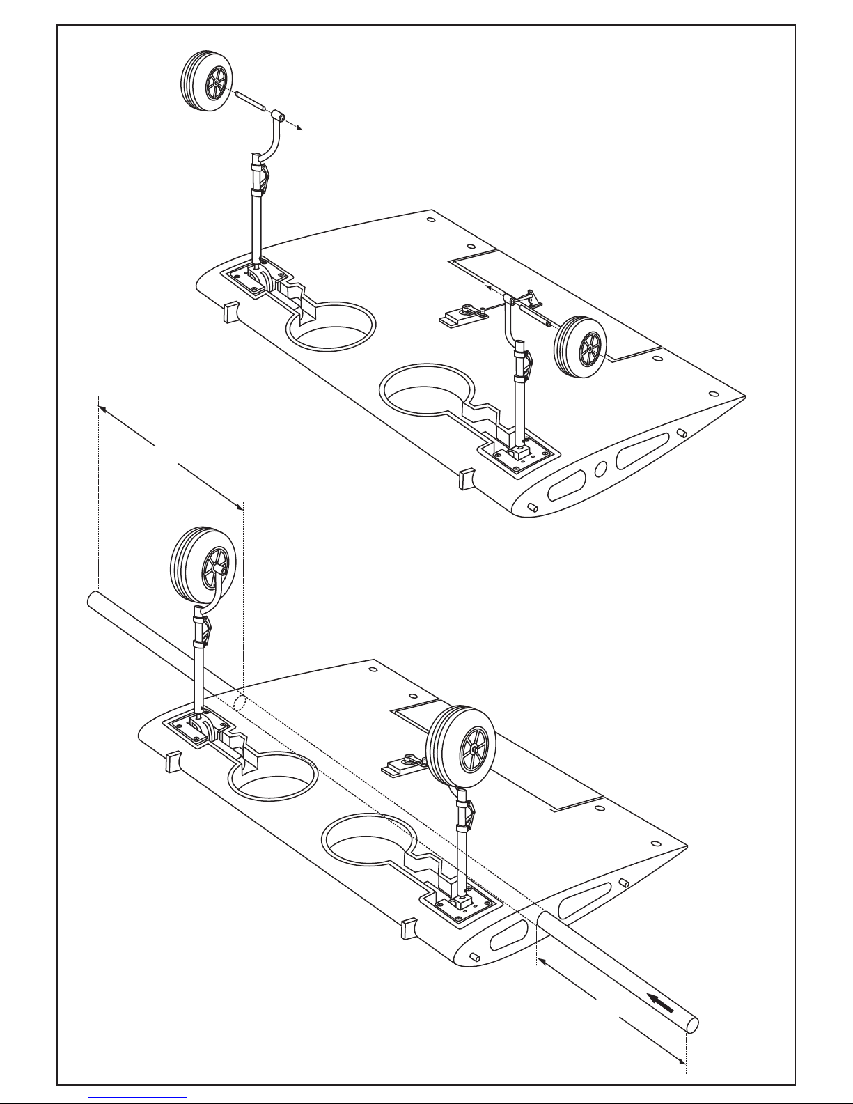
2-WING
A
B
A=B
Carefully, slide the aluminum tube throughout the
center wing with A=B as shown.
3-WING
CA
300mm servo extension
(not included)
500mm servo extension
(not included)
2mm
1mm
1mm
2 mm
Ensure smooth
non-binding
movement
Cut away only
the covering
DO THE SAME WAY WITH OTHER WING
Aileron control horn....2
2x30mm...................4
Flap control horn...........2
2x170mm rod........................4
Connector.............................4
4-WING

A
B
B’
B=B’
FRONT-VIEW
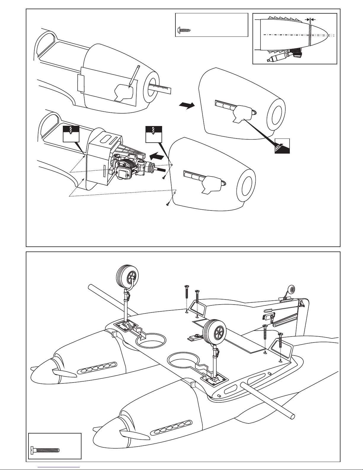
- Remove the engine mount and drill a 15/64”(6mm) hole through
the fire-wall at each of the four marks marked.
- Using a pencil or felt tipped pen, mark the fire wall where the four
holes are to be drilled
- Reposition the engine mounts on to the fire-wall and secure them
with four 4x25mm screw
- Reposition the engine on to the engine mounts so the distance
from the prop hub to the fire wall is 117mm.
117mm
! Engine thrust on balk
head is already adjust
at factory
1.5
TOP-VIEW
! Engine thrust on balk head
is already adjust at factory
! Align the mark on both mounts
with the mark on the fuselage
A
6mm
15/64”
- Mark the engine mounting plate where the four holes are to be
drilled.
Note: Mark the mounting plate through the engine mounting flanges.
- Remove the engine and drill a 1/8”(3mm) holes through the beam
at each of the four marks made above.
- Reposition the engine on the engine mount beams, aligning it with
the holes. Secure the engine to the engine mount using four
3x25mm screws.
3mm
1/8”
Note: Apply Silicon sealer to
each of the 1/8x51/64” screw.
...4
.................4
4x25mm screw
4mm Blind-nut
3x20mm screw
3mm nut
.................4
...4
With hang silencer
FRONT-VIEW
IN CASE OF 2T ENGINE
With side silencer
- Insert the blind-nut with the wooden washer onto each
of the four holes make above.
Wooden washer
Pull the magnetic battery
hatch out of the fuselage
DO THE SAME WAY WITH THE SECOND FUSELAGE
Wooden washer
..............4
5-ENGINE MOUNT - ENGINE

X
To muffler
Filler tube
To engine
3x25mm
screw
Rubber stopper
1
After confirming the direction . Insert this assembly, clunk end first, into the fuel
tank and tighten and screw the fuel tank cap on firmly.
3x35 mm screw
4mm
2
Firewall
117mm
B’
B
B=B’
A
A=A’
A’
! Engine thrust on balk head
is already adjust at factory
Using a aluminum motor mounting plate as a template,
mark the plywood motor mounting plate where the four
holes are to be drilled (2).
Remove the aluminum motor mounting plate and drill
a 1/8”(3mm) hole through the plywood at each of the
four marks marked .
3mm
2
Note: The aluminum motor mounting included with
electric motor set.
5x70mm...........4
5mm nut...........12
5mm washer....16
3mm screw/nut...4
SIDE-VIEW / Seitenansicht
TOP-VIEW / Draufsicht
3
Ensure that the fuel tank clunk does not touch the rear of the fuel tank.
Checking for leaks - block the vents and blow
into the feed - if in doubt submersing the tank
in a blow of water will show up any problems.
Blow
Water
Carefully install the fuel tank to ensure that they will not
shift during flight (secure the fuel tank in place using
foam padding).
4
DO THE SAME WAY WITH THE SECOND FUSELAGE
DO THE SAME WAY WITH THE SECOND FUSELAGE
CA
Li-po battery stand
IN CASE OF GAS ENGINE USING
IN CASE OF BRUSHLESS MOTOR USING
6-FUEL TANK
7-ELECTRIC MOTOR

1-Trial fit the vertical stabilizer in place . Check the alignment of the vertical stabilizer. When you are satisfied with the alignment,
use a pencil to trace around the right and left of the stabilizer where it meets the fuselage.
2-Remove the vertical stabilizer from the fuselage. Using the sharp hobby knife, carefully cut away the covering inside the lines
which were marked above.
3-Spread epoxy (30 minute) onto the right and left and bottom of the vertical stabilizer along the area where the covering was
removed and to the fuselage where the vertical stabilizer mounts.
4-Install the vertical stabilizer into the fuselage and adust the alignment as described in steep 1.
5-Wipe off any excess epoxy using a paper towel .
Allow the epoxy to cure before proceeding to next step.
A
B
Cut away only the covering both
the right and left side
Both the left and
right side
LEFT FUSELAGE AND LEFT VERTICAL STABILIZER
(Looking from the rear of the fuselage)
A
B
Cut away only the covering both
the right and left side
Both the left and
right side
RIGHT FUSELAGE AND RIGHT VERTICAL STABILIZER
(Looking from the rear of the fuselage)
CA
CA
Securely glue together. If coming off during
flight, you lose control of your air plane.
RIGHT VERTICAL STABILIZER
(Looking from the rear of the fuselage)
DO THE SAME WAY WITH THE
LEFT VERTICAL STABILIZER
Note: all wooden vertical stabilizer
mounts on the LEFT and RIGHT
vertical stabilizer must to be mesial.
Securely glue together. If coming off during flight, you lose control of your air plane.
Cut away only
the covering
Cut away only
the covering
CA
Align the horizontal stabilizer mount, then glue the
horizontal stabilizer mount onto the fin, using a
generous amount of thin CA to ensure to strong bond,
apply thin CA along the horizontal stabilizer mount
where it contacts the fin.
8-HORIZONTAL STABILIZER MOUNT
9-VERTICAL STABILIZER

2.mm
5/64”
2.mm
5/64”
Use a pencil, mark the rudder pushrod line
3/8 in. (9.5mm)
Control horn
................2
2x20mm screw
..........4
Without using glue yet, push the rudder and its hinges into the hinge slots in trailing edge of the vertical stabilizer.
When satisfied with the alignment, apply a thin layer of petroleum jelly on one side of each hinges as shown(16A)
Then, apply a thin CA glue on other side of each hinges as shown (16B).
Apply a thin layer of petroleum jelly
VERTICAL STABILIZER
CA
Apply thin CA
glue on the top
of the hinge
VERTICAL STABILIZER
Rudder pushrod exit
LEFT FUSELAGE AND LEFT RUDDER
(Looking from the rear of the fuselage)
RIGHT FUSELAGE AND RIGHT RUDDER
(Looking from the rear of the fuselage)
10-RUDDER
11-RUDDER CONTROL HORN

CA
1- Insert the tail wheel pushrod into the hole on the tail gear control horn (as show).
2- Install the tail wheel control horn in place.
4- Secure the tail wheel control horn in place using a 5/64”(2mm) screw set,
Ensure smooth non-binding movement.
5- Installing the tail wheel hatch (H) in place using a four 5/64x25/64”(2x10mm)
self tapping screws.
6- Attach the tail wheel doors (D) in place using CA glue.
1
3
4
5
2
5/64 in.(2mm)
I.D collar
2x10mm
screw
..........1
Tail landing gear
..........1
............4
2x10mm screw
.................1
Tail wheel controlhorn
2mm I.D collar
6
3- Instal the tail wheel gear in place.
H
D
FUSELAGE - BOTTOM VIEW
DO THE SAME WAY WITH THE SECOND FUSELAGE
Throttle push rod
Rudder push rod
Tail wheel push rod
4-49/64”
(120mm)
2-61/64”
(75mm)
Carefully cut a 2-9/32”(58mm) wide area which is 2-61/64”(75mm) in
length through both the covering and the balsa wood. Remove the
excess balsa.
Put the battery pack into the box (pre-build at factory) and fasten down
with rubber bands or similar, ensuring it will not come loose or rattle
during flights.
Battery area
(in case of 4T engine)
800-1000mah, flat pack
BOTTOM VIEW
Hatch
Hatch
2-9/32”
(58mm)
2”(51mm)
2-61/64”(75mm)
FUSELAGE
BOTTOM
Link the battery wire with the battery extension cord.
Reposition the hatch in place and secure it with CA glue.
RECEIVER BATTERY BOX (IN CASE OF 4T ENGINE USE ONLY)
12-TAIL WHEEL
13-SERVO-BATTERY

Tail wheel push rod
Rudder push rod
................2
....................4
2mm
Connector
Rudder servo
Thrott. servo
X
Rudder pusshrod
D=5/64”(2mm)
3mm Screw
2 mm
RUDDER
SERVO
X
3mm Screw
2 mm
THROTTLE
SERVO
throttle pushrod
D=.050”(1.2mm)
Tail wheel pushrod (D=1.2mm)
Tail wheel push rod
Rudder push rod
Rudder servo
Thrott. servo
1mm
DO THE SAME WAY WITH THE RIGHT FIN AND FUSELAGE
CA
Adhesive
tape
Cut the opening
Board or
transparent
plastic
1-Attach the board or transparent plastic on the side of
the fuselage with the adhesive tape as shown.
2-Using a pencil or felt tipped pen trace around the engine
head where it meet the cowl. Cut the opening the board
or transparent plastic for the engine head as marked
before.
LEFT FIN AND FUSELAGE
LEFT FIN AND FUSELAGE
14-LINKAGES
15-ELEVATOR SERVO
16-COWLING
1~2mm
.
3-Remove the engine and insert the cowl on to the fuselage so the distance from the fire wall to the front of the cowl is 115mm.
Trace around inside the hole on the board or transparent plastic with a pencil.
4-Remove the cowl from the fuselage and carefully cut the opening for the engine head as marked above. Do the same way with the hole
for needle-valve.
5-Again. Insert the cowl on to the fuselage and secure it in place with five 2.5x10mm self tapping screws.
1
15mm
Ruler
2.5X12mm self tapping screw
.................4
1/16”
Cut the opening
1.5mm
1/16”
1.5mm
1/16”
2.5x10mm self
tapping screw
6x40mm nylon bolt
.........2
17-COWLING
18-CENTER WING INSTALLATION
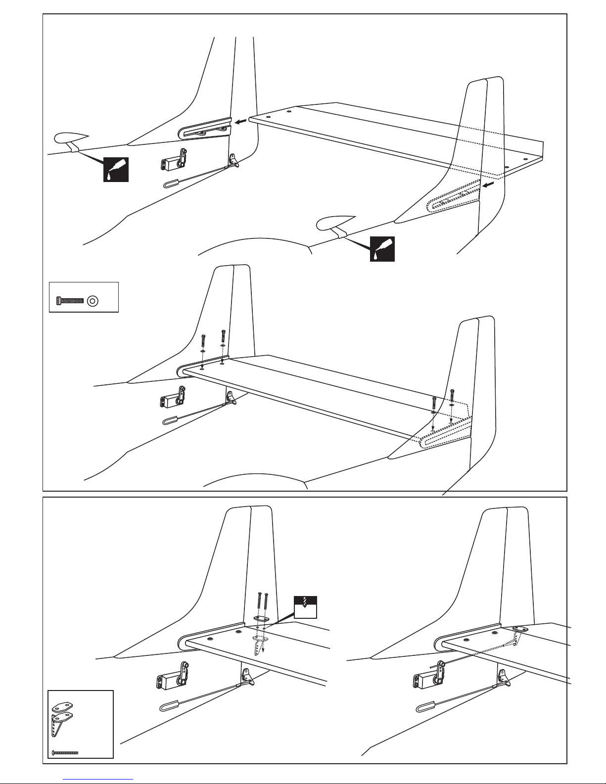
Carefully, slide the horizontal stabilizer into the horizontal stabilizer
mounting slots.
When you are satisfied with the alignment, secure the horizontal stabilizer
in place using the four 3x15mm screws
3x15mm screw
...4
CA
CA
19-HORIZONTAL STABILIZER INSTALLATION
2mm
DO THE SAME WAY WITH OTHER SIDE
OF THE ELEVATOR
RIGHT FIN AND FUSELAGE
RIGHT FIN AND FUSELAGE
DO THE SAME WAY WITH OTHER SIDE
OF THE ELEVATOR
Control horn
................2
2x20mm screw
..........4
20-CONTROL HORN

Link the aileron servo and flap servo to the aileron and flap extension.
Carefully, slide the Right wing and the center wing together
. Ensuring that they are accurately aligned.
Firmly press the right wing and the center wing together and secure the right wing in place using the masking tape.
DO THE SAME WAY WITH THE LEFT WING.
21-WINGS INSTALLATION

Note: The holes on the surface of the top of the left (and right) wing
are pre-drilled at factory.
2.mm drill bit
Aluminum
tube inside
3x15mm screw
T
OP
A
B
3x25mm screw
.........2
3x15mm screw
.
Drill throughout the top side of the
aluminum tube
Secure the left (and right) wing in place using
3x15mm screws.
DO THE SAME WA
Y
WITH OTHER WING
1-Using the plastic air scoop as a template, trace around the outside edge of the plastic air-scoop,and then remove it.
2-Using a sharp hobby knife, cut away the covering inside the lines. Not to cut into the wood.
3-Apply the plastic air scoop in place and secure with CA glue.
Do the same way with the plastic wing cover.
12mm
15/32”
Cut away only the
covering inside
the line
CA
Plastic wing cover
Plastic air scoop
Plastic air scoop
Plastic wing cover
Turn the fuselage below and drill 2mm hole throughout the aluminum
wing joiner as shown.
22-WINGS INSTALLATION

Fuel cap sticker
Pilot LT Col. BOB THACKER
FLIGHT TEST DIVISION A.M.C
WRIGHT FIELD DAYTON. OHIO
Pilot 1ST LT. JOHNNY ARD
FLIGHT TEST DIVISION A.M.C
WRIGHT FIELD DAYTON. OHIO
EMERGENCY
EMERGENCY
Navigator sticker
Sticker
Fuel cap sticker
EMERGENCY
Pilot LT Col. BOB THACKER
FLIGHT TEST DIVISION
A.M.C
WRIGHT FIELD DA
YTON. OHIO
22-DECAL
Wing center section
DO NOT try to fly an out-of-balance model !
Note: If necessary, move the battery pack or add weight to either
the tail or nose until the correct balance is achieved.
13/32”(10mm)
13/32”(10mm)
1-23/64”(35 mm)
1-23/64”(35 mm)
RUDDER
15/64”(6mm)
15/64”(6mm)
AILERON
IMPORTANT: Flying your model at these throws will provide you with the greatest chance for successful first flights.
If,after you have become accustomed to the way the F-82 flies, you would like to change the throws to suit your taste
that is fine. However, too much control throw could make the model difficult to control, so remember, “more is not always
better”.
ELEVATOR
1-13/32”(35mm)
FLAP (center-right-left)
95~98mm
3-5/64”
All details are subject to change without notice !
IMPORTANT:
Please do not clean your model with pure alcohol, only use liquid soap with water or use glass cleaner
to clean on surface of your model to keep the colour not fade.
23-BALANCE - CONTROL SURFACE
 Loading...