

Page 1
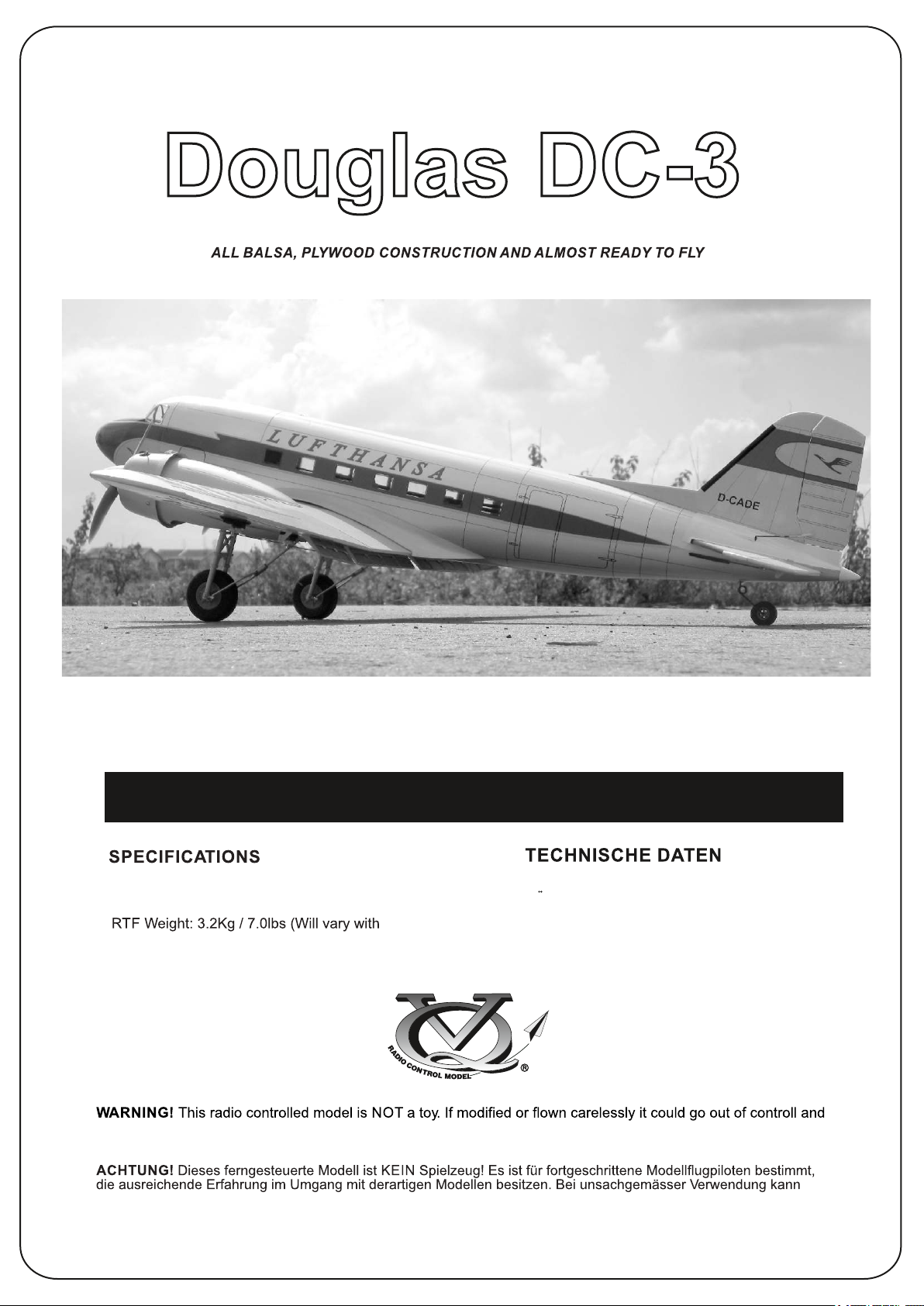
Radio control model / Flugmodell
Instruction manual / Montageanleitung
Wingspan:.........................1800mm (70.8in.)
Length:..............................1200mm (47.2in.)
Electric Motor:.....................x2
Equipment Used).
Radio:....................6 Channel / 4..8 Servos
cause serious human injury or property damage. Before flying your airplane, ensure the air field is spacious enough.
Always fly it outdoors in safe areas and seek professional advice if you are unexperienced.
hoher Personen- und/oder Sachschaden entstehen. Fragen Sie in einem Modellbauverein in Ihrer Nähe um
professionelle Unterstätzung, wenn Sie Hilfe im Bau und Betrieb benötigen. Der Zusammenbau dieses Modells ist
durch die vielen Abbildungen selbsterklärend und ist für fortgeschrittene, erfahrene Modellbauer bestimmt.
Spannweite:...................................1800mm
Lange:............................................1200mm
Elektroantrieb.............(siehe nächste Seite)
Brushless Motor:.............x 2
Fluggewicht:.......................................3.2Kg
Fernsteuerung................6 Kanal / 4..8 Servos
Page 2
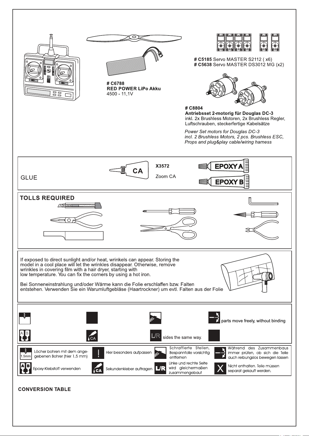
Sonderzubehör (empfohlen) / Optional Accessories (recommended):
# C8802
Fernsteuerung GigaProp 6
Radio Set GigaProp 6
#C9218
Elektrisches Einziehfahrwerk
Electric Retracts
Alle Infos zu diesem Zubehör unter:
More infos about these Accessories:
www.pichler-modellbau.de
Klebestoffe (nicht mitgeliefert)
(Purchase separately)
Hobby knife
Needle nose Pliers
Sander
Masking tape - Straight Edged Ruler - Pen or pencil - Drill and Assorted Drill Bits
.........................................................
.........................................................
.........................................................
.........................................................
.........................................................
.........................................................
.........................................................
.........................................................
.........................................................
.........................................................
.........................................................
X3598-120
5-Min Epoxy
Cyanoacrylate Glue (thin type)
Hex Wrench
Phillip screw driver
Awl
Scissors
Wire Cutters
zu bekommen. Die Kanten können Sie mit einem Bügeleisen behandeln. Nicht zuviel Hitze anwenden !
Symbols used throughout this instruction manual, comprise:
Drill holes using the stated
1.5mm
size of drill
(in this case 1.5 mm )
A
B
Use epoxy glue
Take particular care here
!
Apply cyano glue
Hatched-in areas:
remove covering
film carefully
Assemble left and right
L/R
Check during assembly that these
Not included.
These parts must be
X
purchased separately
Read through the manual before you begin, so you will have an overall idea of what to do.
1.0mm = 3/64”
1.5mm = 1/16”
2.0mm = 5/64”
2.5mm = 3/32”
3.0mm = 1/8”
4.0mm = 5/32”
5.0mm = 13/64”
6.0mm = 15/64”
10mm = 13/32”
12mm = 15/32”
15mm = 19/32”
20mm = 51/64”
25mm = 1”
30mm = 1-3/16”
45mm = 1-51/64”
Low seting
Page 3
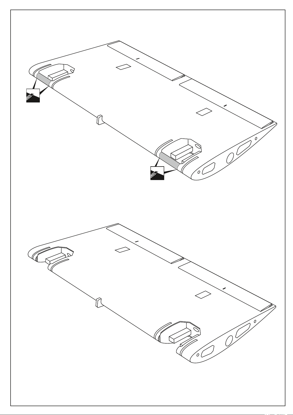
1- CENTER WING:ELECTRIC RETRACT INSTALLATION (OPTION)
Tragflächenmittelstück
CENTER WING - BOTTOM VIEW
Ansicht von unten
Cut away the leading edge
as show.
Note: Cut away the leading edge
in case of the electric retract use only.
Cut away the leading edge
as show.
Page 4
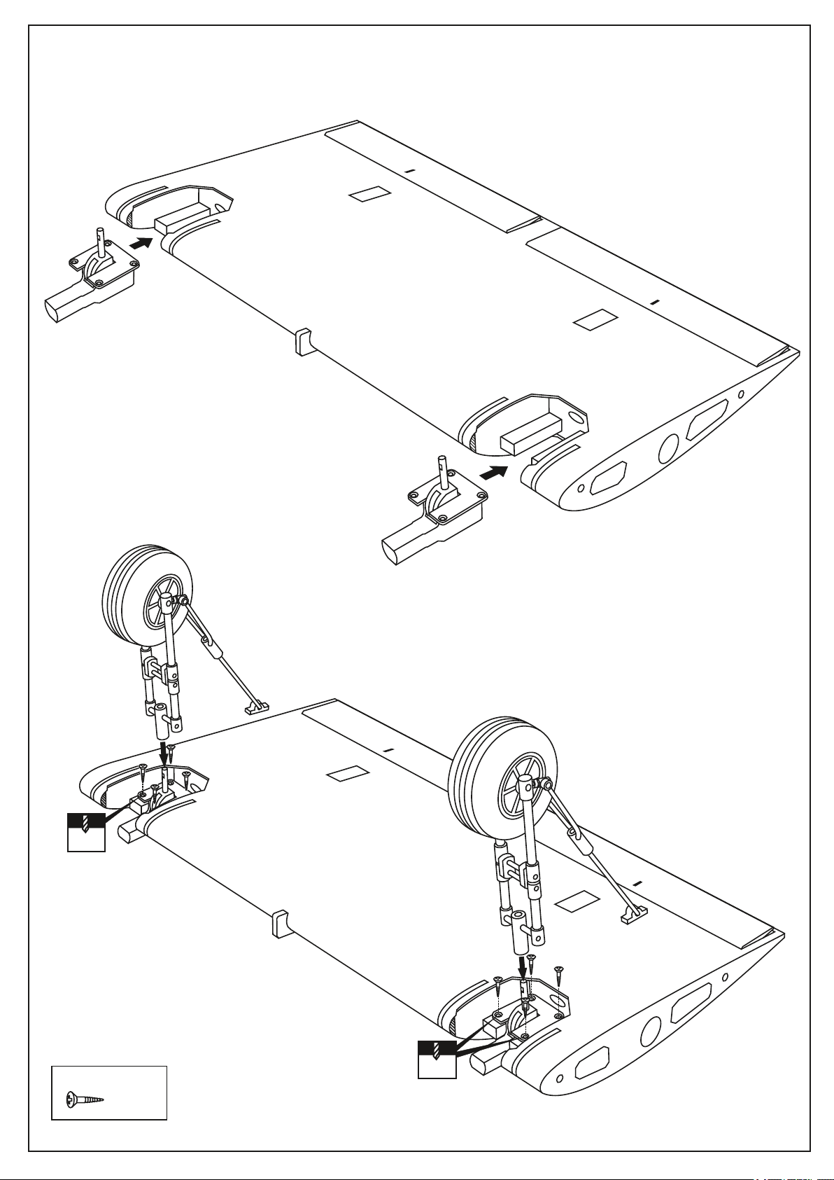
2- CENTER WING: ELECTRIC RETRACT INSTALLATION (OPTION)
Tragflächenmittelstück
Note: Connect the electric retract to the receiver,
with the retract switch on your radio in ON position,
the electric retract will be in extended position.
CENTER WING - BOTTOM VIEW
Ansicht von unten
Step 2A
(Option) #C9218
3x12mm
2mm
Secure the electric retracts in place using
the eight 3x12mm screws.
3x12mm screw
.........8
Step 2B
3x12mm
2mm
Page 5
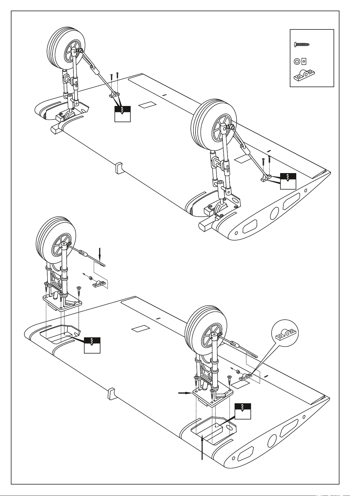
3- CENTER WING: ELECTRIC RETRACT INSTALLATION (OPTION)
Tragflächenmittelstück
3x12mm screw
......4
2mm
CENTER WING - BOTTOM VIEW
Ansicht von unten
Step 3A
3mm collar
.........2
.........2
2mm
Fahrwerksabstützung
Landing gear brace
3x12mm
2mm
Fahrwerksträger
STEP 3B: FIXED GEAR INSTALLATION
Note: In case of fixed gear using, do not cut the leading edge
Landing gear mount
1-Position the landing gear mount (plywood) onto
the hard wood mounts as shown.
2-Using the felt tipped pen, mark the location of the four
landing gear mount holes.
3-Remove the landing gear mount and drill the four mounting
holes as marked in the previous step using a 2mm drill bit.
4-Again, position the landing gear mount onto the hard wood
mounts and secure it in place using a four 3x12mm screws.
2mm
Hartholzträger
Hard wood mount
Page 6
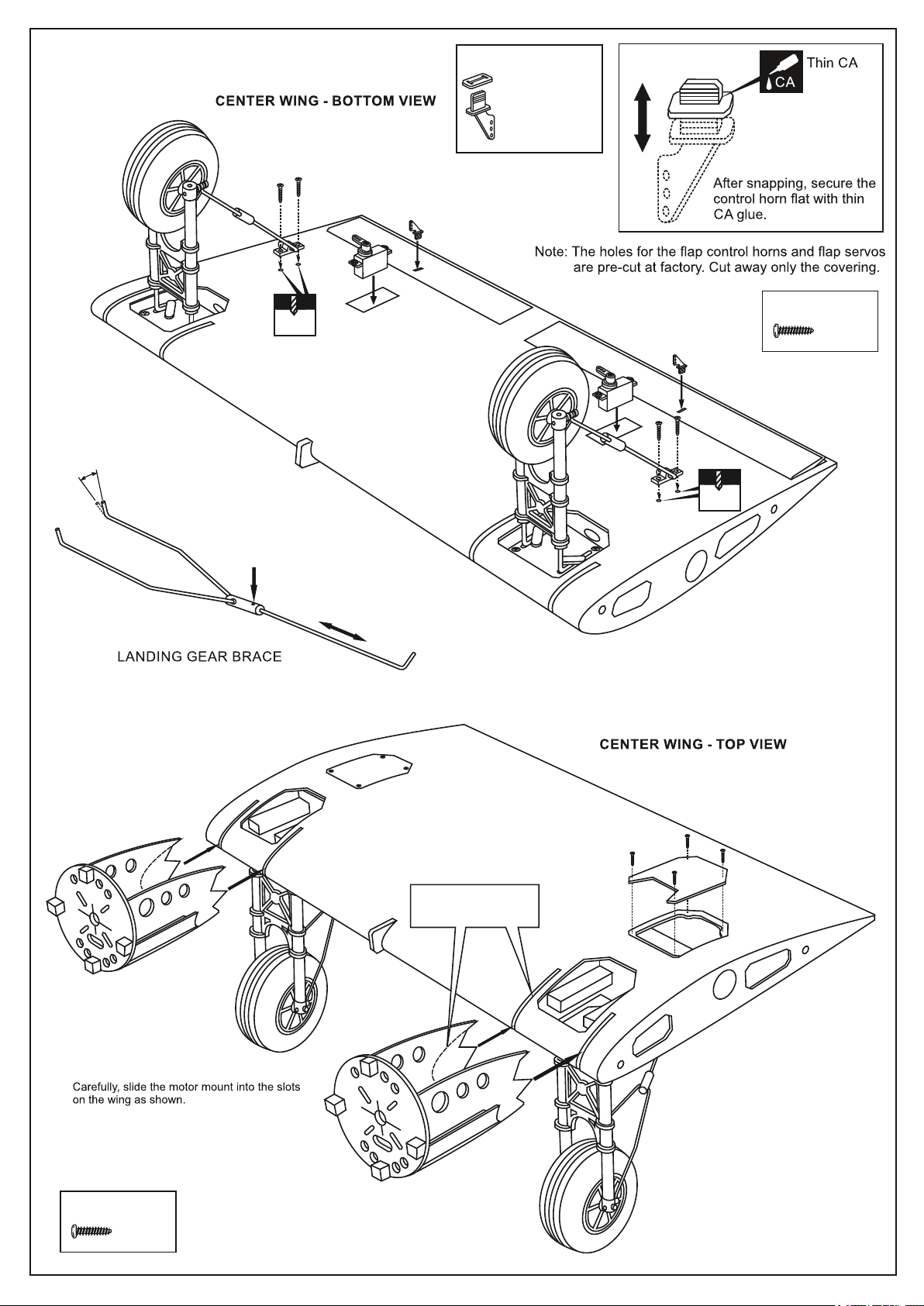
4- CENTER WING
Tragflächenmittelstück
Plastic control horn
Bend the steel wire for
the adjusting.
Ansicht von unten
Step 4A
3x12mm screw
2mm
.....................1
3x12mm screw
......4
2mm
Adjuster screw
Fahrwerksabstützung
Step 4B
2x8mm
Korrekt ausrichten
Ensuring that they are
accurately aligned.
2X8mm screw
......8
Page 7
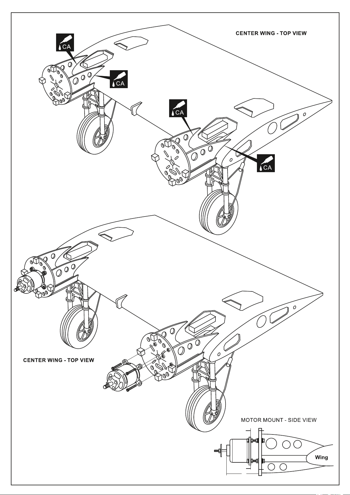
5- CENTER WING
Ansicht von oben
Step 5A
Ansicht von oben
Step 5B
-Using a aluminum motor mounting as a template,
mark the firewall where the four holes are to be drilled.
-Remove the motor and drill a 1/8”(3mm) hole through the plywood at
each of the four marks marked .
B=B’
A= 60-65mm
Motorträger Seitenansicht
B
B’
A
Page 8
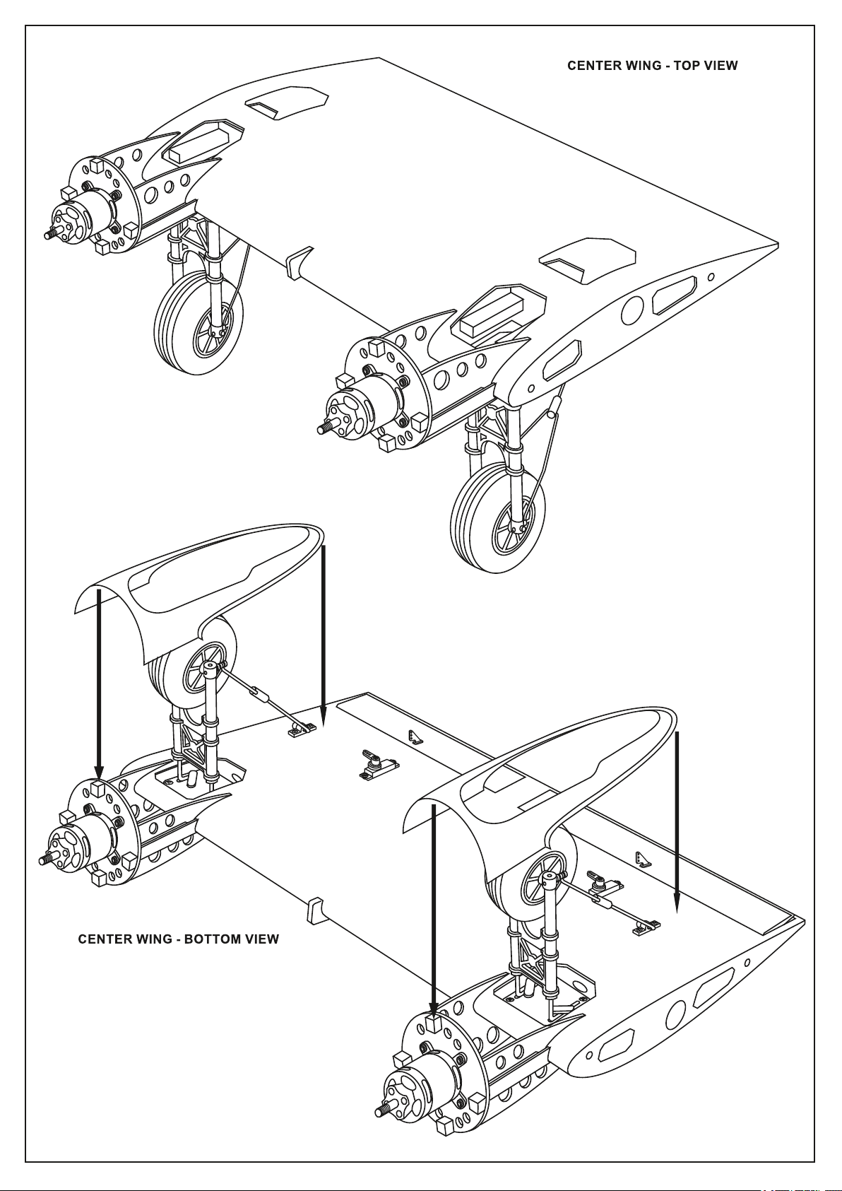
6- CENTER WING
Tragflächenmittelstück
Ansicht von oben
Step 6A
Step 6B
Page 9
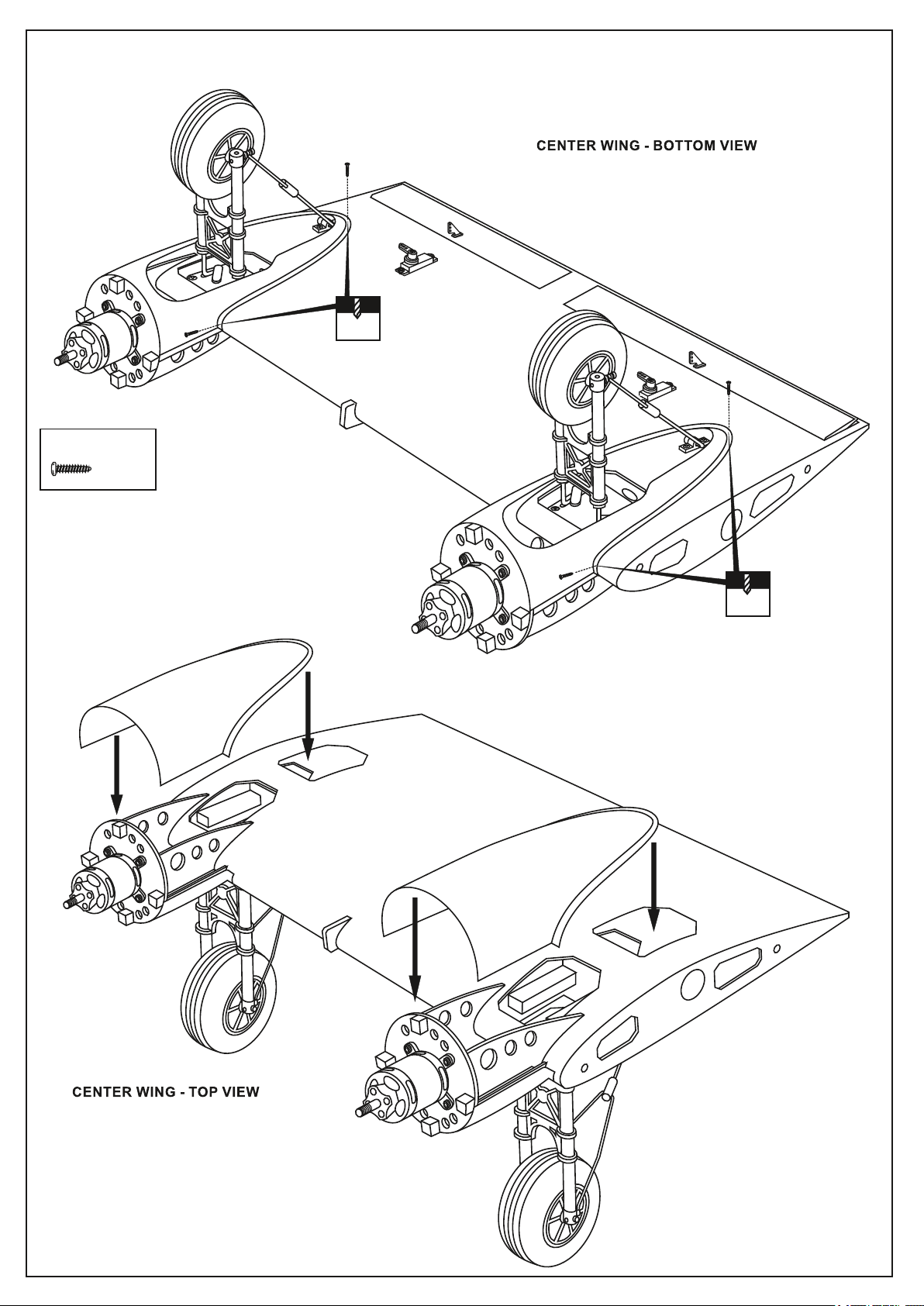
7- CENTER WING
Tragflächenmittelstück
2X8mm screw
......6
2x8mm
Ansicht von unten
Step 7A
1.5mm
2x8mm
1.5mm
Step 7B
Page 10
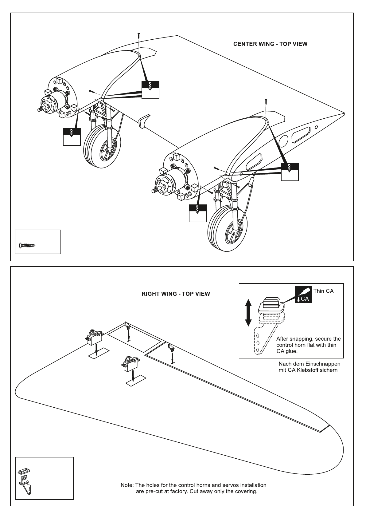
8- CENTER WING
2x8mm
1.5mm
2x8mm
Ansicht von oben
Step 8A
1.5mm
2x8mm
2x8mm
1.5mm
2X8mm screw
......14
9- RIGHT (LEFT) WING
1.5mm
Step 9A
Plastic control horn
.....................2
Die Löcher für die Ruderhörner und Servos
sind werksseitig vorgesehen und können unter
der Folie ertastet werden.
Page 11
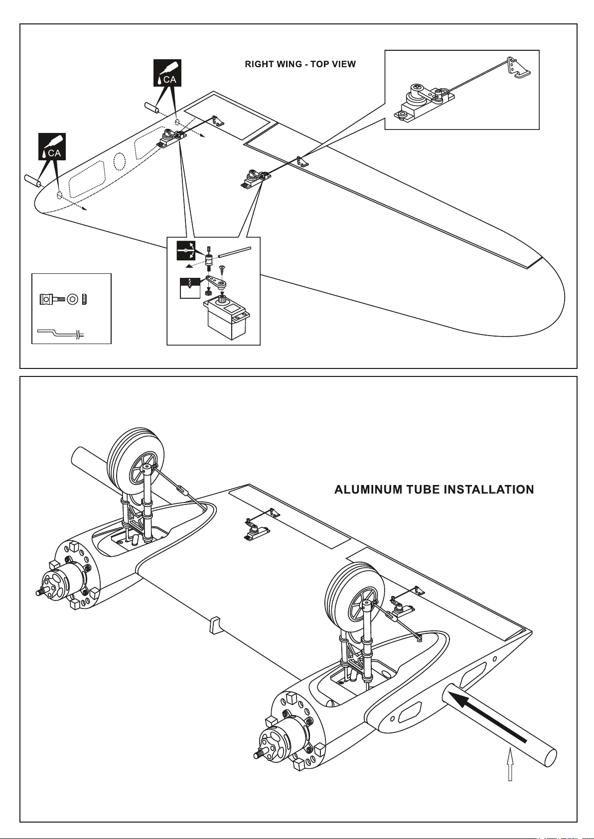
10- RIGHT (LEFT) WING
Rechte und linke Flächenhälfte
Rechte Flächenhälfte von oben
Step 10A
Connector
...2
1.2x175mm rod
....2
11- CENTER WING
Tragflächenmittelstück
2 mm
Aluminium Flächensteckungsrohr
19x749mm aluminum tube
Page 12
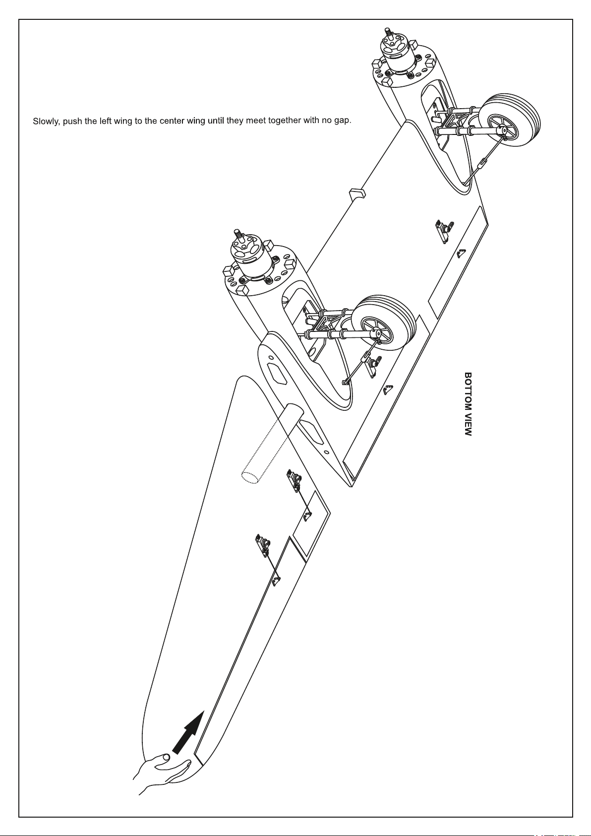
12- JOINING THE WING
Flächenteile langsam und spaltfrei zusammenschieben
Page 13
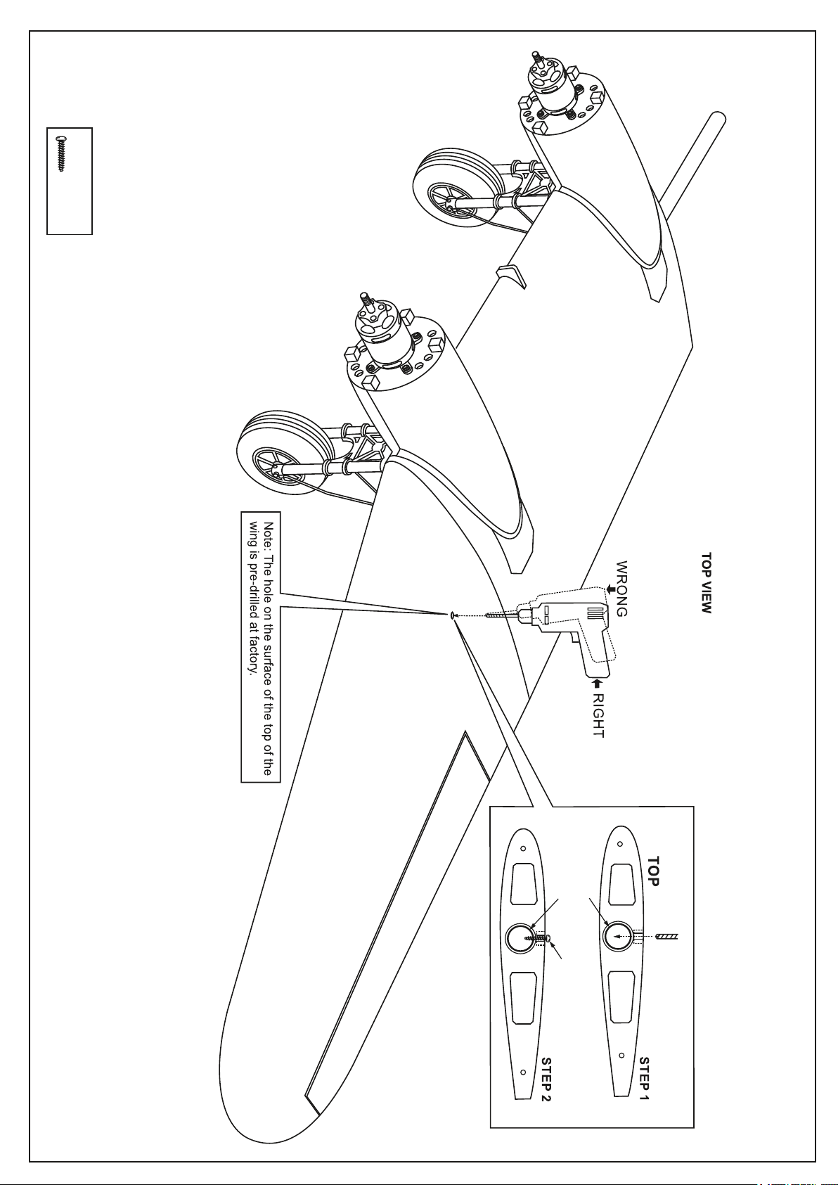
13- JOINING THE WING
Do the same way with the right wing.
3x15mm screw
.........2
Aluminum
tube inside
Secure the wing in place
using 3x15mm screw.
2.mm drill bit
Page 14
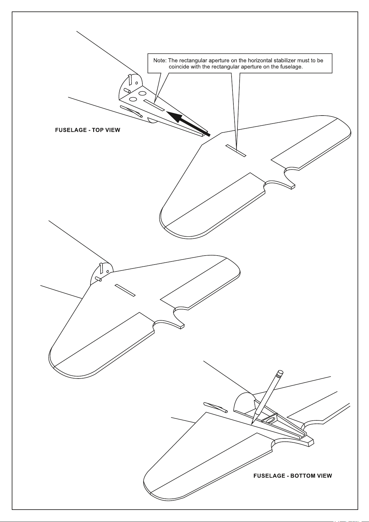
14- HORIZONTAL STABILIZER
Trial fit the horizontal stabilizer in place on the fuselage.
Check the alignment of the horizontal stabilizer by measuring
from a fixed point along the center line of the fuselage to the
leading edge on each side of the horizontal stabilizer.
The distance must be equal on both sides.
Bitte korrekt ausrichten
When you are satisfied with the alignment, use a
pencil to carefully trace around the bottom of the
stabilizer where it meets the fuselage
Page 15
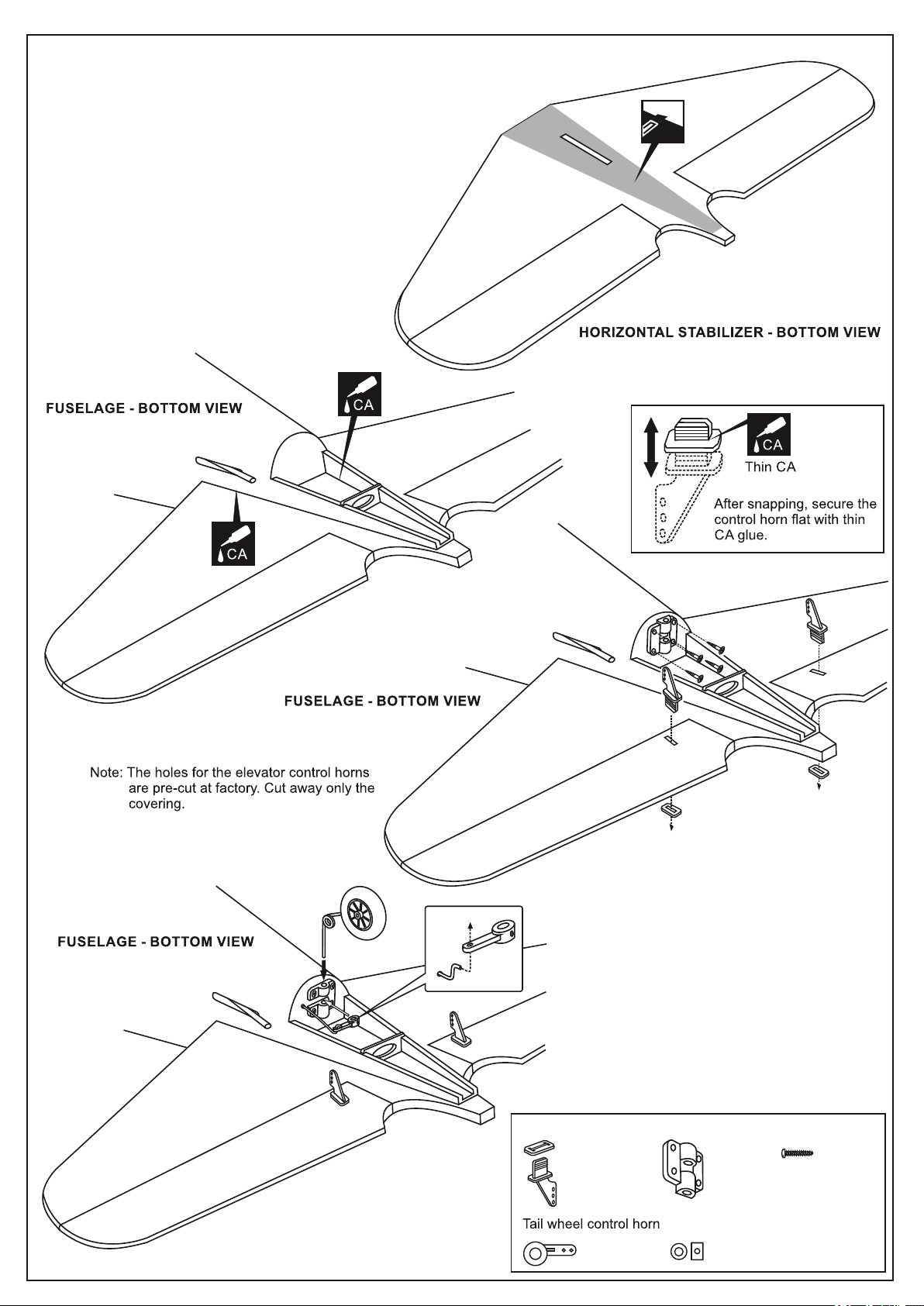
15- HORIZONTAL STABILIZER AND TAIL WHEEL
Remove the horizontal stabilizer from the
fuselage. Using a straight edge and a sharp
hobby knife, carefully cut away the covering
inside the lines which were marked.
Be cautious not to cut into the wood - this will
weaken the structure.
1
Plastic control horn
1- Insert the tail wheel pushrod into the hole on the
tail gear control horn (as show).
2- Install the tail wheel control horn in place.
3- Instal the tail wheel gear in place.
4- Secure the tail wheel control horn in place using a
2mm screw set, Ensure smooth non-binding
movement.
.................2
............1
Tail gear mount
............1
2mm I.D collar
............1
3x10mm screw
............4
Page 16
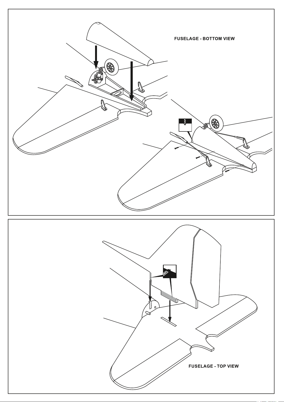
16- TAIL WHEEL COVER
1.5mm
2x8mm
17- VERTICAL STABILIZER
2x8mm
Cut away only
the covering
Remove the horizontal stabilizer from the
fuselage. Using a straight edge and a sharp
hobby knife, carefully cut away the covering
inside the lines which were marked.
Be cautious not to cut into the wood - this will
weaken the structure.
Page 17
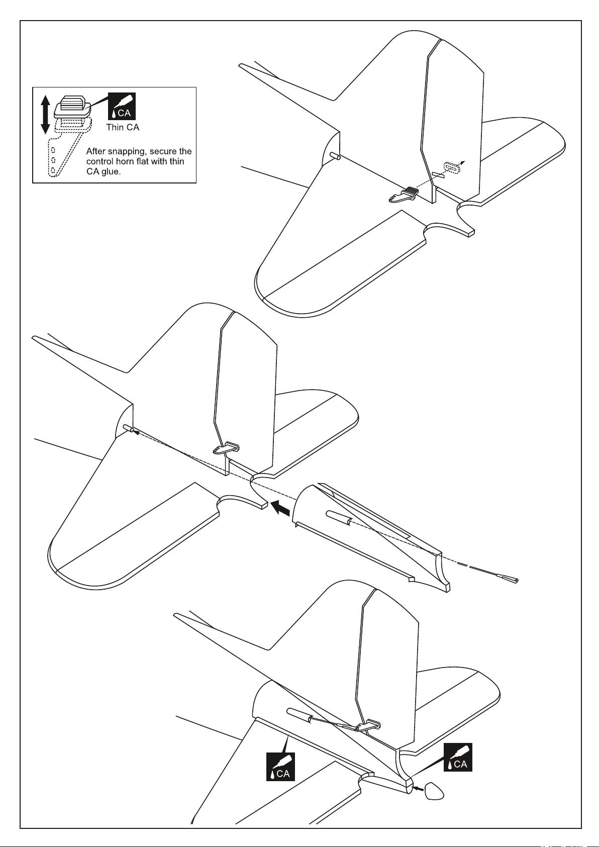
18- VERTICAL STABILIZER continued
Slide the rudder push-rod through the plastic
cover and the plastic push-rod tube into the
fuselage.
Page 18
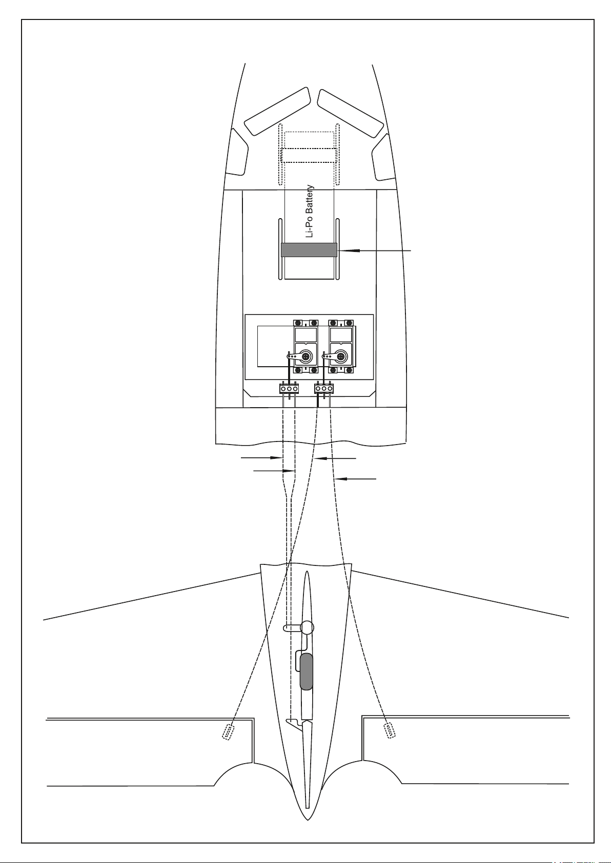
19- LINKAGES
Belt
Tail wheel push-rod
Rudder push-rod
Left elevator push-rod
Right elevator push-rod
Page 19
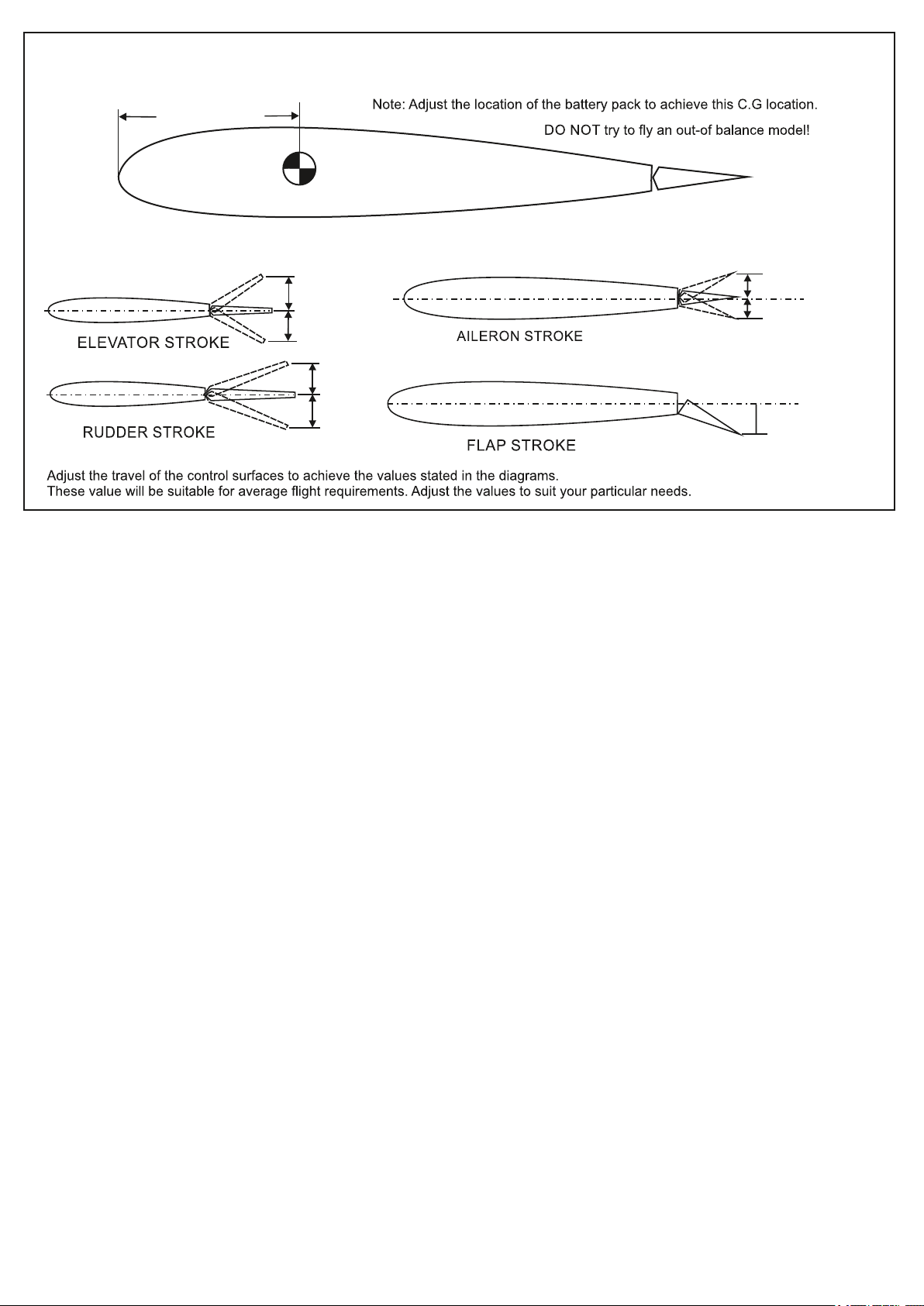
20- BALANCE AND CONTROL SURFACE
(100 ~ 110mm)
Wing center section
Schwerpunkt und Ruderausschläge
Höhenruder
Seitenruder
12mm
12mm
20mm
20mm
15mm
15mm
Querruder
20-25mm
Landeklappen
 Loading...