

Page 1
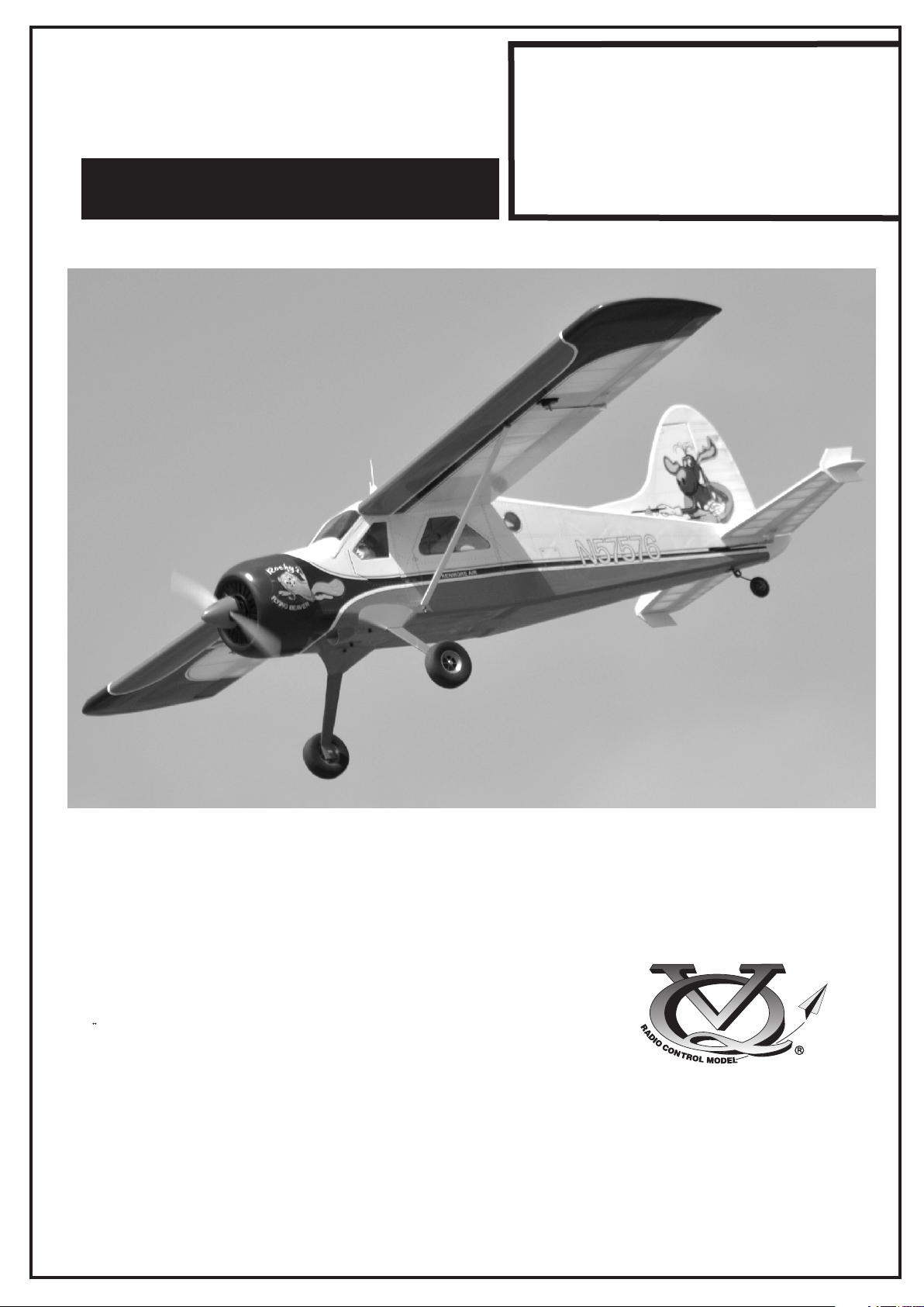
Radio control model / R/C Flugmodel
26 - 30cc Gas Engine
DE HAVILLAND
Or Electric equivalent
INSTRUCTION MANUAL
MONTAGEANLEITUNG
DHC 2
BEAVER
SPECIFICATIONS
Wingspan 112in.
Length 68 in.
Gas Engine 26 - 30cc
Radio 6 Channel / 8 Servos
TECHNISCHE DATEN
Spannweiter 2.850mm
Lange .727mm
Verbrennerantrieb 26 - 30cc
Fernsteuerung 6 Kanal / 8 Servos
WARNING! This radio controlled model is NOT a toy. If modified or flown carelessly it could go out of controll and
cause serious human injury or property damage. Before flying your airplane, ensure the air field is spacious enough.
Always fly it outdoors in safe areas and seek professional advice if you are unexperienced.
ACHTUNG! Dieses ferngesteuerte Modell ist KEIN Spielzeug! Es ist für fortgeschrittene Modellflugpiloten bestimmt,
die ausreichende Erfahrung im Umgang mit derartigen Modellen besitzen Bei unsachgemäßer Verwendung kann
hoher Personen- und/oder Sachschaden entstehen. Fragen Sie in einem Modellbauverein in Ihrer Nähe um
professionelle Unterstützung, wenn Sie Hilfe im Bau und Betrieb benötigen. Der Zusammenbau dieses Modells ist
durch die vielen Abbildungen selbsterklärend und ist für fortgeschrittene, erfahrene Modellbauer bestimmt.
Page 2
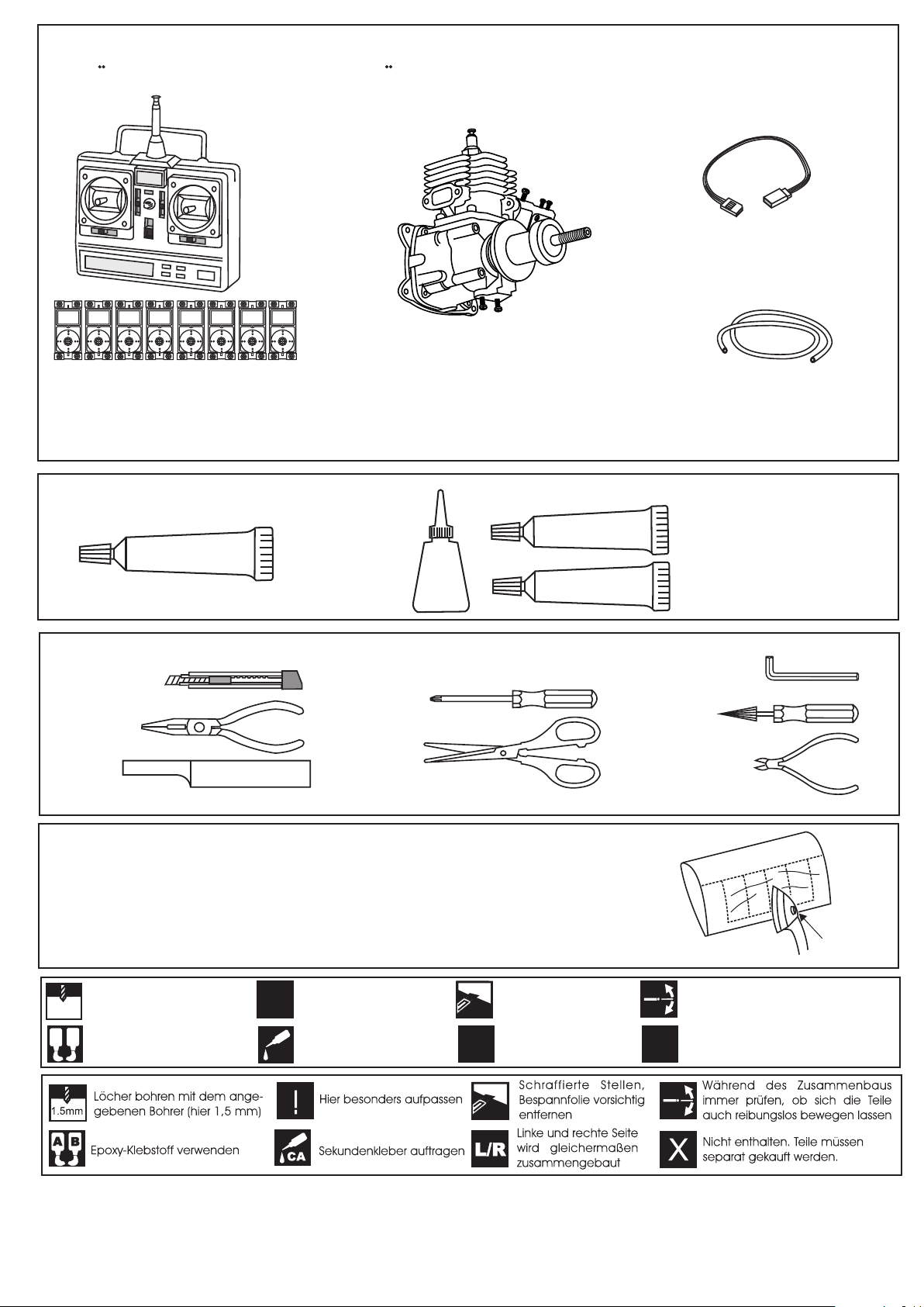
REQUIRED FOR OPERATION (Purchase separately)
BENOTIGTE KOMPONENTEN FUR DEN ABFLUG (Nicht enthalten)
Extension for aileron
servo, Flap servo.
Gas Engine: 26 ~ 30cc
Minimum 6 channel radio
for airplane with 8 servos
.Motor control x1 .Aileron x2
.Elevator x2 .Rudder x1
.Flap x 2
GLUE
(Purchase separately)
SILICON
Silicon sealer
TOLLS REQUIRED
Hobby knife
Needle nose Pliers
Sander
Masking tape - Straight Edged Ruler - Pen or pencil - Drill and Assorted Drill Bits
.........................................................
.........................................................
.........................................................
.........................................................
.........................................................
.........................................................
.........................................................
.........................................................
.........................................................
.........................................................
.........................................................
Cyanoacrylate
Glue
Klebstoff
CA
(Purchase separately)
Phillip screw driver
Scissors
EPOXY A
EPOXY B
Nylon tube
Epoxy Glue (5 minute type)
Epoxy-Klebstoff (5min-Typ)
Epoxy Glue (30 minute type)
Epoxy-Klebstoff (30min-Typ)
Hex Wrench
Awl
Wire Cutters
If exposed to direct sunlight and/or heat, wrinkels can appear. Storing the
model in a cool place will let the wrinkles disappear. Otherwise, remove
wrinkles in covering film with a hair dryer, starting with
low temperature. You can fix the corners by using a hot iron.
Bei Sonneneinstrahlung und/oder Wärme kann die Folie erschlaffen bzw. Falten
entstehen. Verwenden Sie ein Warumluftgebläse (Haartrockner) um evtl. Falten aus der Folie
zu bekommen. Die Kanten können Sie mit einem Bügeleisen behandeln. Nicht zuviel Hitze anwenden !
Drill holes using the stated
size of drill
1.5mm
(in this case 1.5 mm Ø)
A
B
Use epoxy glue
Take particular care here
!
Apply cyano glue
CA
Hatched-in areas:
remove covering
film carefully
Assemble left and right
L/R
sides the same way.
Check during assembly that these
parts move freely, without binding
Not included.
These parts must be
X
purchased separately
Read through the manual before you begin, so you will have an overall idea of what to do.
CONVERSION TABLE
1.0mm = 3/64”
1.5mm = 1/16”
2.0mm = 5/64”
2.5mm = 3/32”
3.0mm = 1/8”
4.0mm = 5/32”
5.0mm = 13/64”
6.0mm = 15/64”
10mm = 13/32”
12mm = 15/32”
15mm = 19/32”
20mm = 51/64”
25mm = 1”
30mm = 1-3/16”
45mm = 1-51/64”
Low setting
Page 3
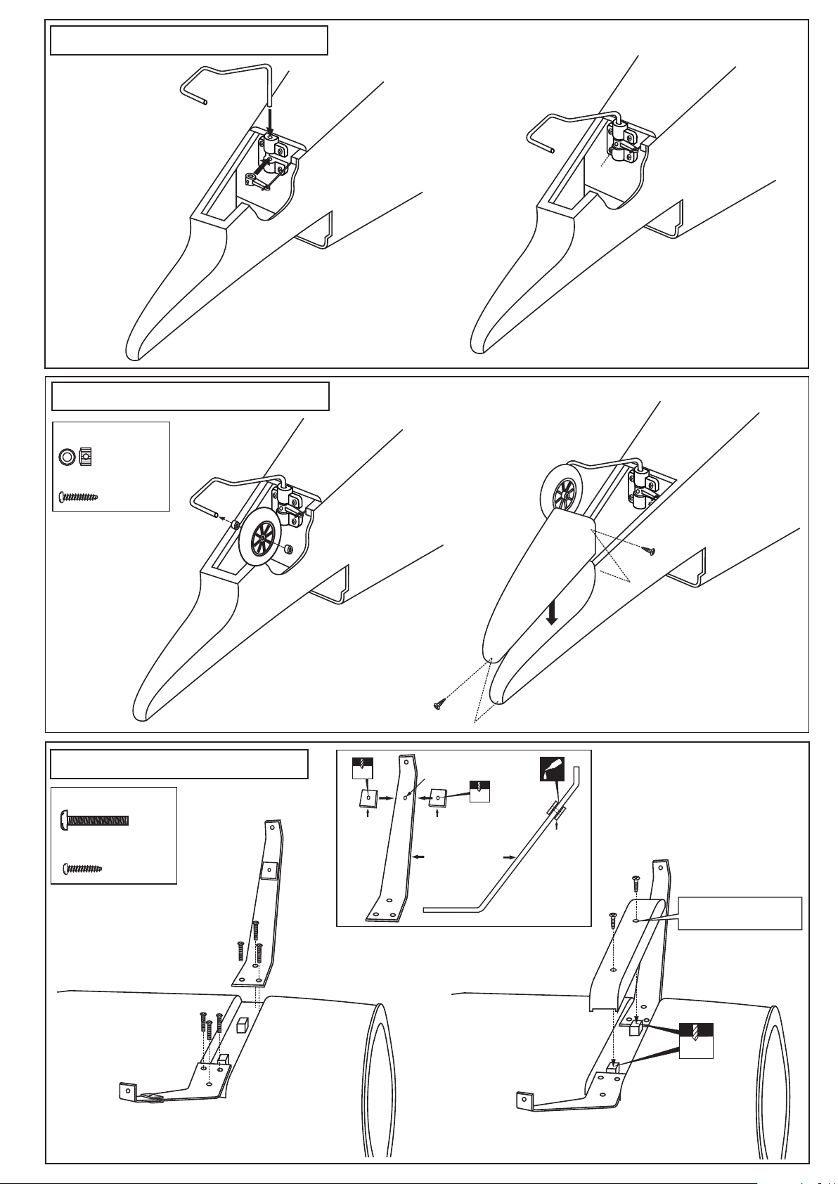
1- Tail gear / Heckspornrad
3
FUSELAGE - REAR - BOTTOM VIEW
UNTERSICHT
2
1
6- Tail gear / Heckspornrad
2.5mm collar
.........2
2x6mm screw
.........3
4
FUSELAGE - REAR - BOTTOM VIEW
UNTERSICHT
3- Landing gear / Fahrwerk
5X50mm screw
....2
3x10mm screw
.........4
3
3
2x6mm screw
4mm
1
3mm plywood
This hole is pre-drilled
at factory.
4mm
3mm plywood
Aluminum landing gear
2
1
SIDE VIEW
CA
3mm plywood
Two holes on the landing gear
hatch are pre-drilled at factory
4
1.5mm
Page 4
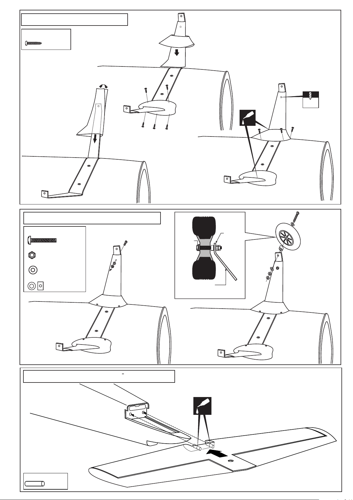
4- Landing gear / Fahrwerk
2x6mm screw
.........10
6
9
5
5- Landing gear / Fahrwerk
5X50mm screw
............2
5mm nut
.....................4
5mm washer
.....................6
5mm collar
...................2
10
7
5x50mm
screw
Aluminum landing
gear
Hauptfahrwerk
4mm nut
8
CA
4mm
7
6- Horizontal Stabilizer / Hohenleitwerk
6x22mm dowel
........2
! Securely glue together. If coming off during flight,
you lose control of your air plane.
CA
TOP VIEW / Draufsicht
Page 5
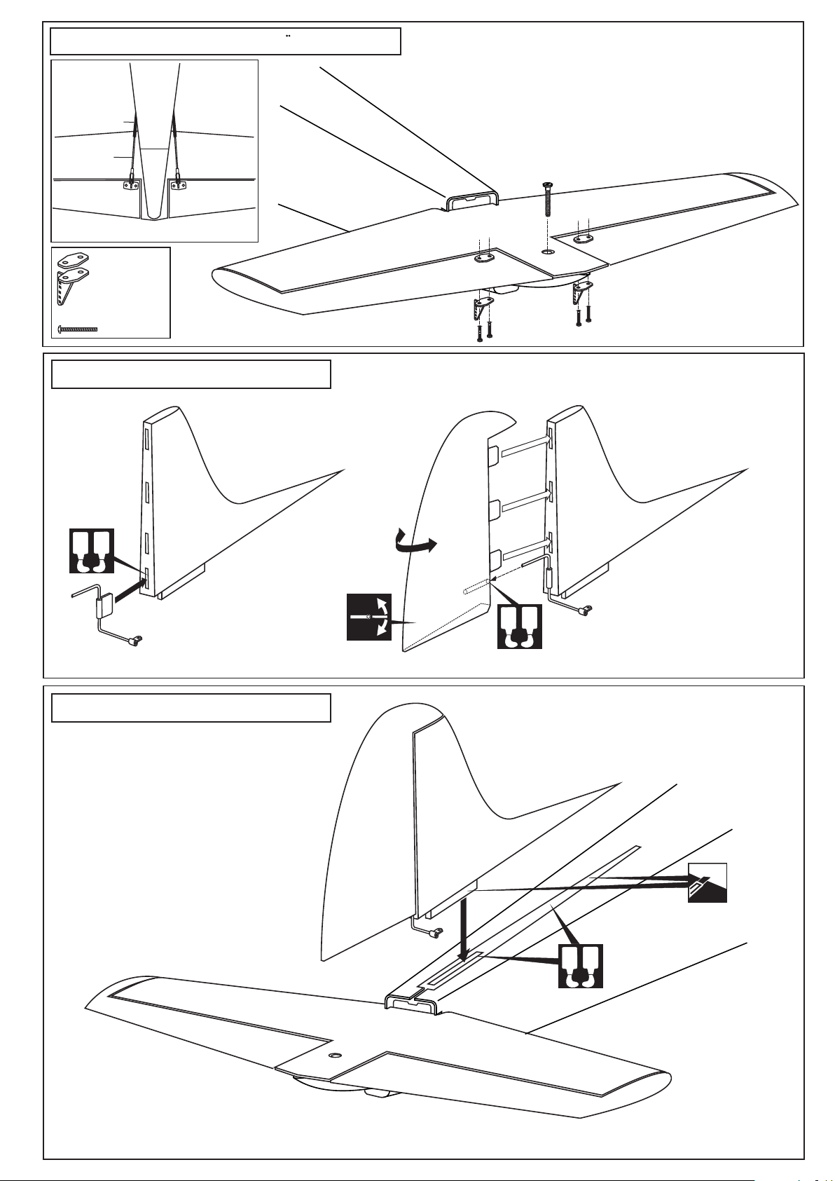
7- Horizontal Stabilizer / Hohenleitwerk
Nylon push rod guider
Elevator push rod
ELEVATOR ELEVATOR
BOTTOM - VIEW / Unteransicht
Control horn
................2
2x30mm screw
..........4
TOP VIEW / Draufsicht
8- Vertical Tail / Seitenruder
A
B
9- Vertical Tail / Seitenruder
* WARNING: When removing any covering from
the airframe, please ensure that you secure the
cut edge with CA or similar cement. This will
ensure the covering remain tight.
! Securely glue together. If coming off during flight,
you lose control of your air plane.
A
B
TOP VIEW / Draufsicht
! Securely glue together. If coming off during flight,
you lose control of your air plane.
A
Cut away only
the covering
B
Page 6
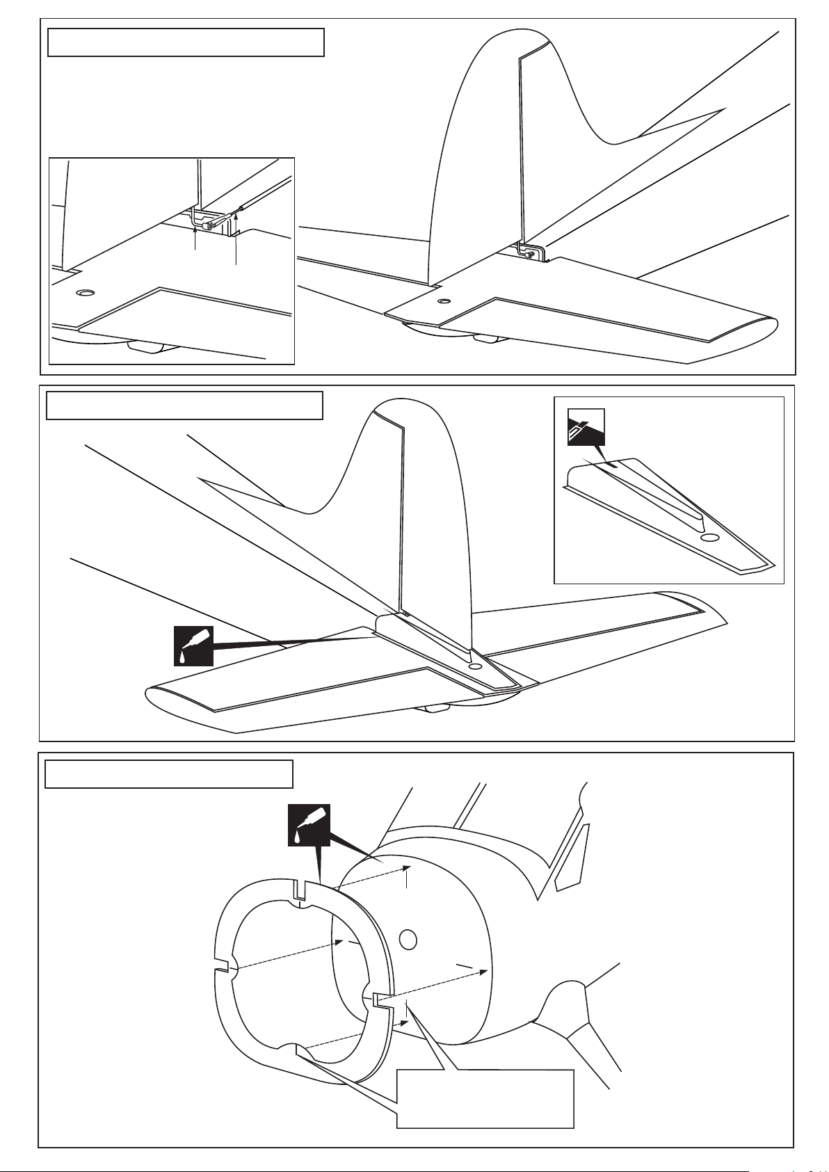
10- Vertical Tail / Seitenruder
TOP VIEW / Draufsicht
Rudder torque rod
Rudder push rod
11- Vertical Tail / Seitenruder
CA
12- Cowling /
TOP VIEW / Draufsicht
Motorhaube
CA
BCOW
FL1
Align the mark on “BCOW”
with the mark on the
fire-wall (FL1)
Page 7
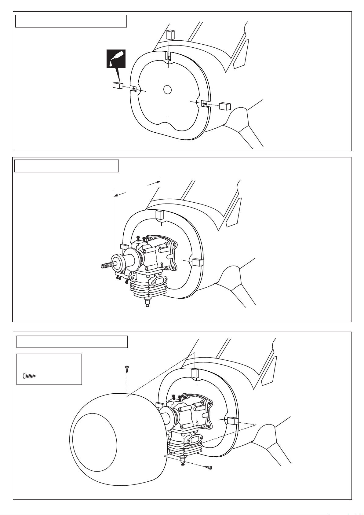
13- Cowling /
Motorhaube
BCOW
CA
14- Engine /
15- Cowling /
Motoreinbau
150-150mm
Motorhaube
3x8mm screw
Blechschraube
..............3
Page 8
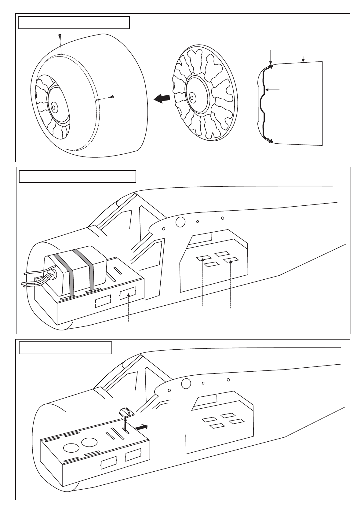
15A- Dummy engine
2x6mm screw
16- Fuel tank /
ABS Dummy engine
2x6mm screw
Cowling
Dummy engine
Kraftstofftank
17- Battery installation
Throttle servo
BTC
1
Rudder servo
Elevator servo
2
1- Pull the BTC out of the hatch
2- Slide the hatch (as shown)
Page 9
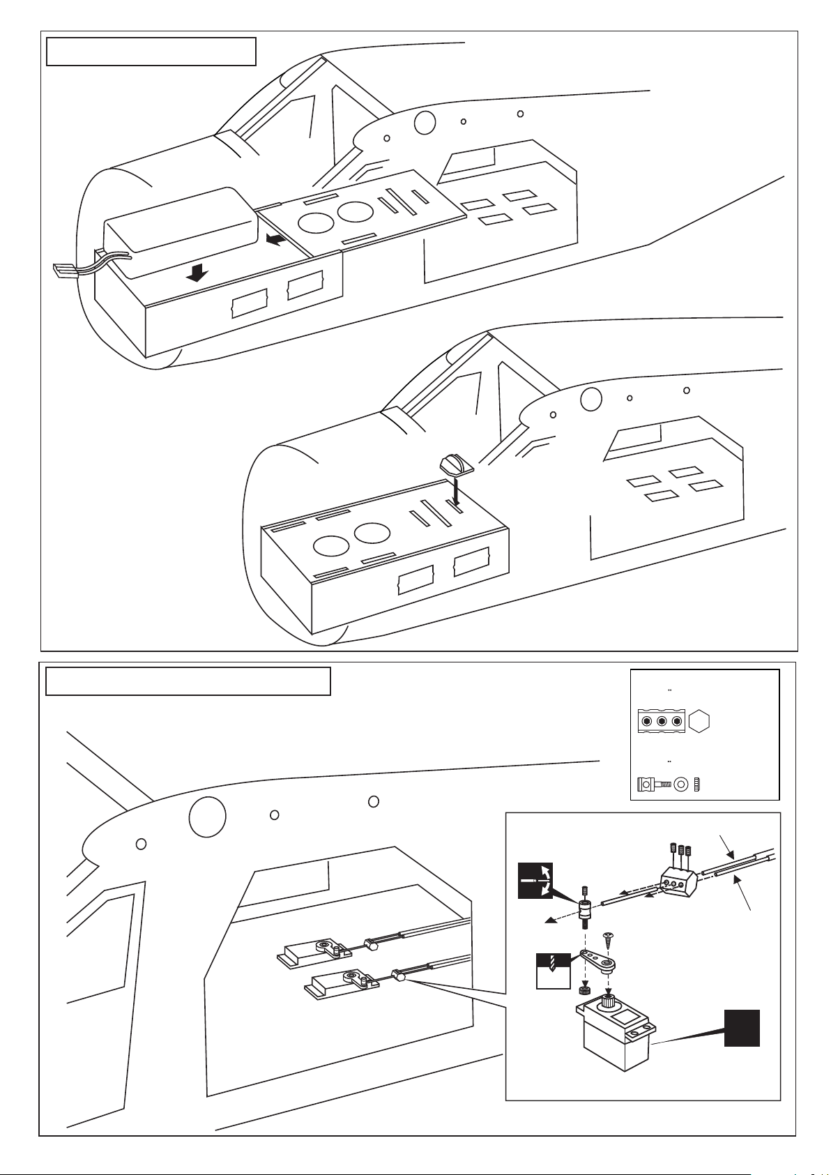
18- Battery installation
1
1- Install the LI-po battery into the box.
2- Pull the hatch (as shown).
2
BTC
19- Linkage / Anlenkungen
Reposition the BTC for secure the hatch in place.
Connector
Gestangeanschluss
............2
Connector
Gestangeanschluss
............2
Elevator pushrod
3mm set Screw
Elevator pushrod
or rudder pusshrod
D=5/64”(2mm)
2 mm
Tail wheel pushrod
D=.050”(1.2mm)
X
ELEVATOR / RUDDER SERVO
Page 10
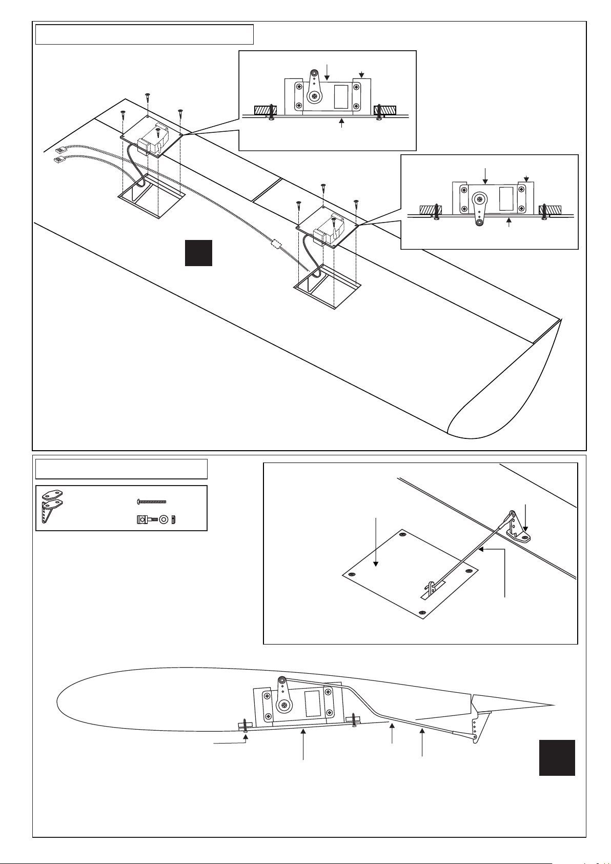
20- Servo installation / Servoeinbau
5/64(2x10mm)
screw
X
Aileron servo
extension
cord
Flap servo
WING BOTTOM
5/64(2x10mm)
screw
Servo mount
Flap servo hatch
Aileron servo
WING BOTTOM
Servo mount
Aileron servo hatch
BOTTOM - VIEW / Unteransicht
21- Linkages / Anlenkungen
Control horn
...................2
2x30mm screw
..........4
......2
TOP
Aileron servo / Querruder servo
Aileron control horn
Aileron servo hatch
Aileron push rod
Wing - Bottom view / Unteransicht
CAUTION: one of the flap servos is revert servo
2x10mm screw
BOTTOM
1- Place the flap servo onto the servo mounts and secure it in place using the four screws included with the servo.
2- Install the flap push rod connector onto the hole in the flap servo arm and insert the push rod through the push rod
connector.
3- Place the flap servo hatch in its mount and secure it in place using four 2x10mm screws.
Flap servo hatch
Push rod exit
Flap push rod
L/R
Page 11
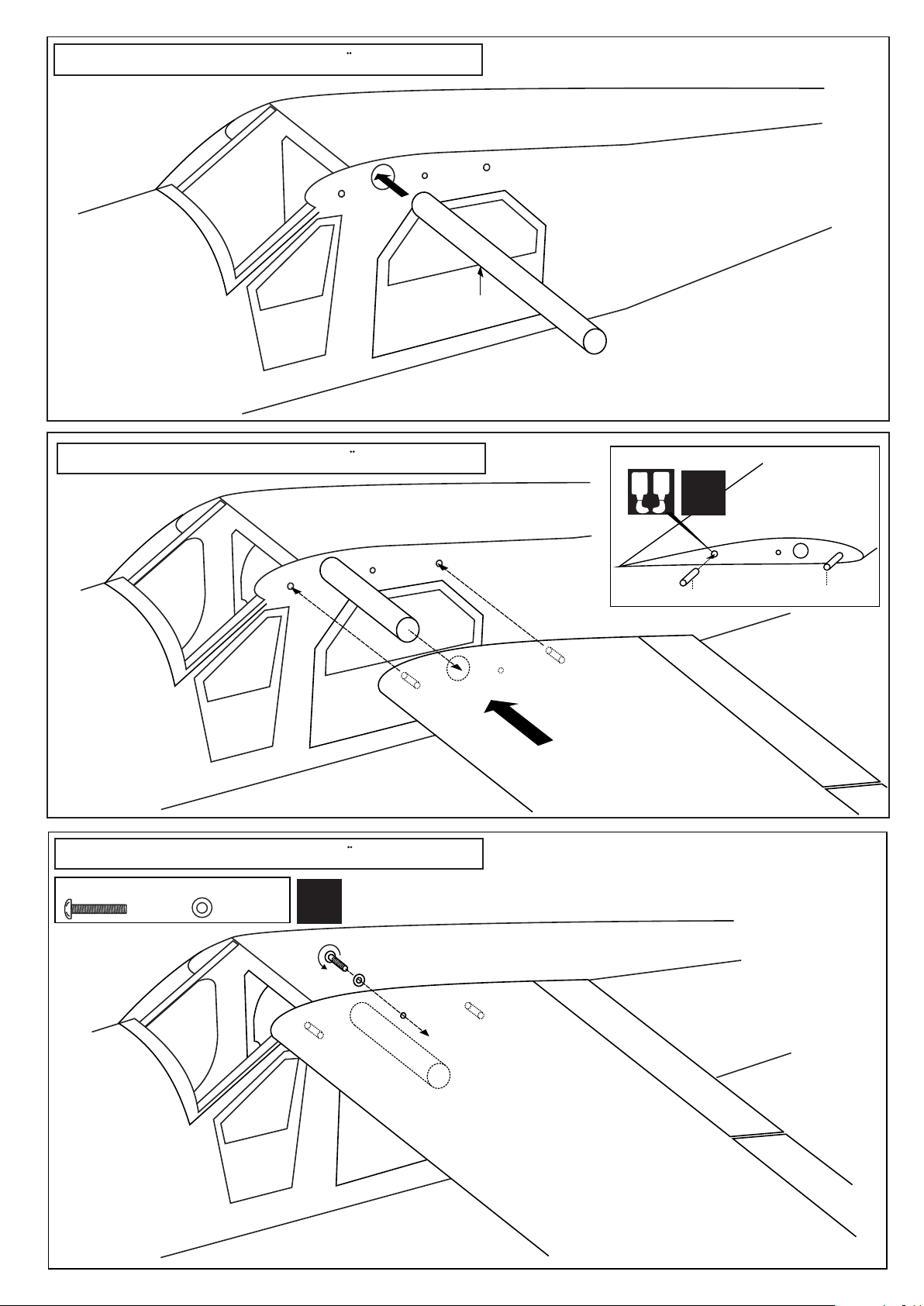
22- Installing the wing / Tragflacheneinbau
Aluminum tube
23- Installing the wing / Tragflacheneinbau
A
B
L/R
24- Installing the wing / Tragflacheneinbau
5x20mm screw
.....2
5mm washer
...............2
L/R
Wooden dowel
Wooden dowel
Page 12
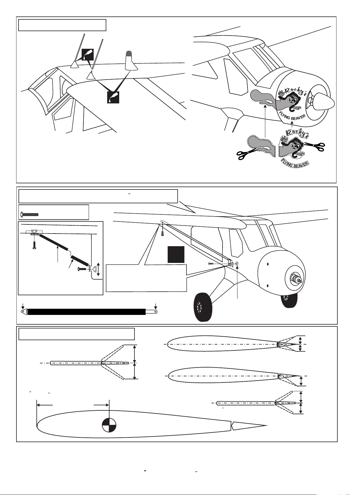
25- Decor / Aufkleber
CA
2
CA
4
Note: Cut out the stickers and apply them in the proper area.
Do not peel the backing paper off all at once. Peel off one corner of the backing and cut off
with scissors. Arrange sticker on model and when satisfied adhere the corner without backing.
Carefully peel back the rest of the backing while at the same time adhering the rest of the
sticker.
Try not to make air bubbles, if there are some, carefully puncture sticker (center of bubble) but not model surface
with the tip of the knife or sharp pin and squeeze out the air.
At curves stretch sticker and apply a little heat so that no ceases occur. Cut off the excess that is produced.
4
26- Installing the wing / Tragflacheneinbau
3x15mm screw / Schraube
The blindnut in the wing
is installed at factory.
............................2
3x15mm
sscrew
Wing brace
Wing
3x15mm
sscrew
L/R
The hole on the bottom of the
wings and the slot on the side of
the fuselage are pre-drilled at
factory
1
3
2
1
3
To the bottom of the wing
Wing brace ( right - left)
27- Balance / Schwerpunkt
Rudder
To the side of the fuselage
30mm
This blindnut can be
move up and down
Aileron
Querruderausschlag
Flap
Seitenruderausschlag
30mm
Do not try to fly an out-of balance model!
Uberprufen Sie vor dem Flug den Schwerpunkt.
Elevator
90 ~ 95mm
Hohenruderausschlag
IMPORTANT:
Please do not clean your model with pure alcohol, only use liquid soap with water or use glass cleaner
to clean on surface of your model to keep the colour not fade.
15mm
15mm
20mm
15mm
15mm
All details are subject to change
without notice !
Technische Anderungen und Irrtumer
vorbehalten !
 Loading...