

Page 1
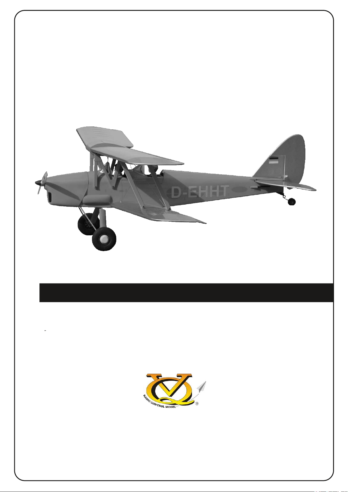
R/C Flugmodell R/C Airplane Model
TIGER MOTH
DH-82
ALL BALSA, PLYWOOD CONSTRUCTION AND ALMOST READY TO FLY
Anleitung / Instructions
TECHNISCHE DATEN
Spannweite ...................................1400mm
Lange ............................................1180mm
Elektroantrieb.................................... 750W
Verbrennerantrieb ...............7.45cc - 11.5cc
Fluggewicht .......................................3,5Kg
Fernsteuerung ........ 5 Kanal / 4 .. 5 Servos
WARNING! This radio controlled model is NOT a toy. If modified or flown carelessly it could go out of controll and
cause serious human injury or property damage. Before flying your airplane, ensure the air field is spacious enough.
Always fly it outdoors in safe areas and seek professional advice if you are unexperienced.
SPECIFICATIONS
Wingspan:......................................1400mm
Length:...........................................1180mm
Electric Motor:....................................750W
Glow Engine:.................... .46 2-T / .70 4-T
RTF Weight: 3.Kg (will vary with equipment
use)
Radio:....................5 Channel / 4-5 Servos
Function: Ailerons-Elevator-Rudder-Throttle
VQ No: VQA139R/Y/DK
ACHTUNG! Dieses ferngesteuerte Modell ist KEIN Spielzeug! Es ist für fortgeschrittene Modellflugpiloten bestimmt,
die ausreichende Erfahrung im Umgang mit derartigen Modellen besitzen. Bei unsachgemässer Verwendung kann
hoher Personen- und/oder Sachschaden entstehen. Fragen Sie in einem Modellbauverein in Ihrer Nähe um
professionelle Unterstätzung, wenn Sie Hilfe im Bau und Betrieb benötigen. Der Zusammenbau dieses Modells ist
durch die vielen Abbildungen selbsterklärend und ist für fortgeschrittene, erfahrene Modellbauer bestimmt.
Page 2
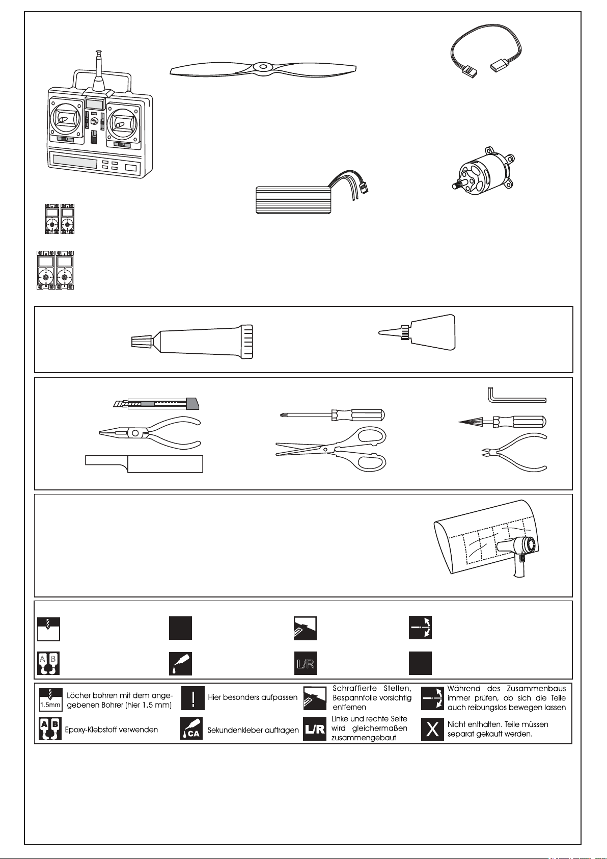
Für den Betrieb erforderlich / Items needed
MASTER SERVO
DS3012MG x2, # C7578
MASTER SERVO
DS4020 x2, # C4994
Klebstoff /Glue
5-Minute Epoxy, # X3598-120
Luftschraube 12x5 (Holz), # C9714‚
Propeller 12x5 (Wooden)
Fernsteuerung GigaProp 6
# C8802
Radio Set GigaProp 6
LiPo Akku 4500 - 11,1V # C9421
LiPo Battery 4500- 11,1V
Akku Klettbänder
# C4738
Passendes Zubehör finden Sie hier:
Find all suitable accessories here:
Battery Straps
www.pichler-modellbau.de
(separat erhältlich - available seperately)
5min Epoxy
Sekundenkleber / CA Glue, # X3572
Servokabelverlängerung x2, # C2036
Servo Extensionwire
Servokabelverlängerung x2, # C1393
Servo Extensionwire
Brushless Power Set
BOOST 40 # C9109
CA
Werkzeug / Tools
Hobby knife
(nicht im Lieferumfang / not included)
Phillip screw driver
Hex Wrench
Awl
Needle nose Pliers
Scissors
Wire Cutters
Sander
.........................................................
.........................................................
.........................................................
.........................................................
.........................................................
.........................................................
.........................................................
.........................................................
.........................................................
.........................................................
.........................................................
Masking tape - Straight Edged Ruler - Pen or pencil - Drill and Assorted Drill Bits
If exposed to direct sunlight and/or heat, wrinkels can appear. Storing the
model in a cool place will let the wrinkles disappear. Otherwise, remove
wrinkles in covering film with a hair dryer, starting with
low temperature. You can fix the edges by using a hot iron.
Bei Sonneneinstrahlung und/oder Wärme kann die Folie erschlaffen bzw. Falten
entstehen. Verwenden Sie einen Haartrockener, um die Folie ggf. zu spannen.
Die Kanten können Sie vorsichtig mit einem Bügeleisen behandeln. Nicht zuviel Hitze anwenden !
Symbols used throughout this instruction manual, comprise:
Drill holes using the stated
1.5mm
size of drill
(in this case 1.5 mm )
A
B
Use epoxy glue
Take particular care here
!
Apply cyano glue
CA
Hatched-in areas:
remove covering
film carefully
Assemble left and right
L/R
sides the same way.
Check during assembly that these
parts move freely, without binding
Not included.
These parts must be
X
purchased separately
Low seting
Read through the manual before you begin, so you will have an overall idea of what to do.
CONVERSION TABLE
1.0mm = 3/64”
1.5mm = 1/16”
2.0mm = 5/64”
2.5mm = 3/32”
3.0mm = 1/8”
4.0mm = 5/32”
5.0mm = 13/64”
6.0mm = 15/64”
10mm = 13/32”
12mm = 15/32”
15mm = 19/32”
20mm = 51/64”
25mm = 1”
30mm = 1-3/16”
45mm = 1-51/64”
Page 3
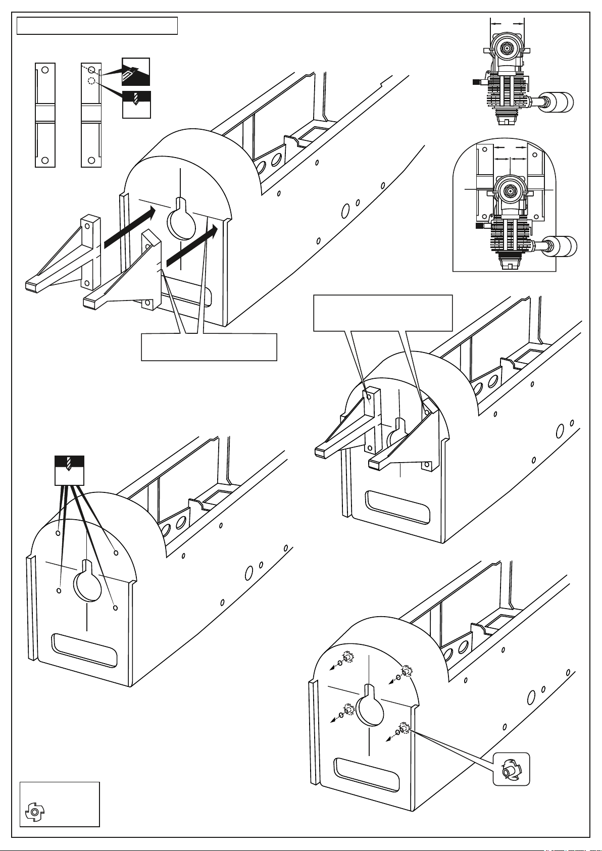
1- Engine installation
A
LEFT
RIGHT
4mm
1A
Engine mounts
Front-view
1B
! Engine thrust on balk head
is already adjust at factory
! Align the mark on both mounts
with the mark on the fuselage
Using a pencil or felt tipped pen,
mark the fire wall where the four
holes are to be drilled
A
B
B=B’
B’
Remove the engine mount and drill
a 13/64”(5mm) hole through the
fire-wall at each of the four marks
marked.
13/64”
5mm
1D
1C
4mm Blind-nut
..........4
1E
Attach the four blind-nut to the fire-wall as show
Page 4
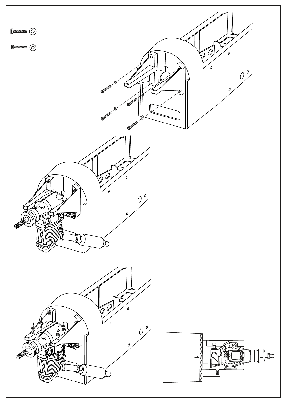
2- Engine installation
4x25mm screw - washer
...................4
3x25mm screw - washer
....................4
2B
Reposition the engine mounts on to the fire-wall
and secure them with four 4x25mm screw.
2A
2C
Reposition the engine on to the engine mounts so
the distance from the prop hub to the fire wall is
130mm.
- Mark the engine mounting plate where the four
holes are to be drilled.
Note: Mark the mounting plate through the engine
mounting flanges.
- Remove the engine and drill a 1/8”(3mm) holes
through the beam at each of the four marks made
above.
- Reposition the engine on the engine mount beams,
aligning it with the holes. Secure the engine to the
engine mount using four 1/8x51/64”(3x25mm)
screws.
Note: Apply Silicon sealer to
each of the 3x25mm screw.
FIRE-WALL
130mm
FUSELAGE - BOTTOM VIEW
Page 5
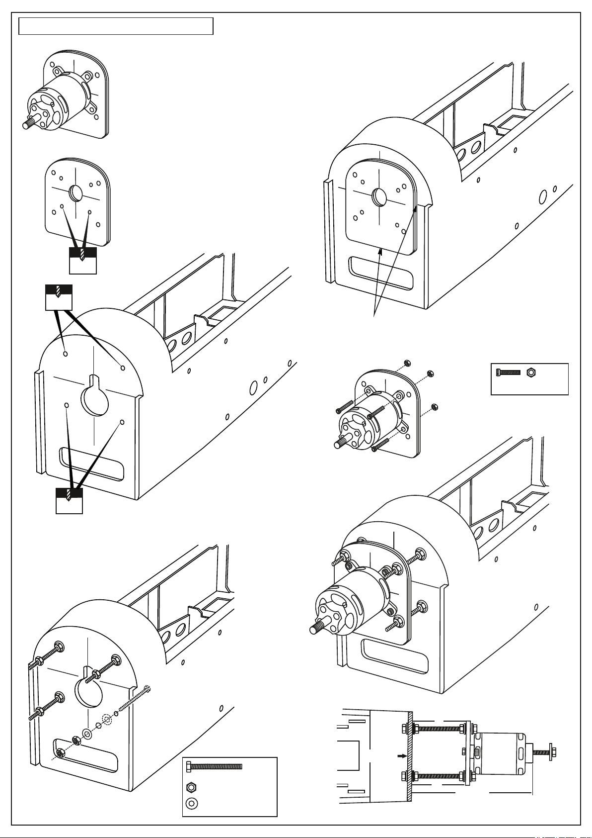
3- Electric Motor installation
Using a aluminum motor mounting plate
as a template, mark the plywood motor
mounting plate where the four holes are
to be drilled.
3A
Remove the aluminum motor mounting
plate and drill a 1/8”(3mm) hole through
the plywood at each of the four marks
marked .
3B
3mm
5mm
Using a wooden motor mounting plate as a template,
mark the fire-wall where the four holes are to be drilled.
3C
3D
5mm
Remove the wooden motor mounting plate and drill
a 5mm hole through the fire-wall at each of the four
marks marked .
3E
! Align the mark on wooden motor
mounting plate with the mark on
the fire-wall.
3F
Secure the Motor to the wooden
motor mounting plate using the
four 3mm bolts.
3mm bolt / nut...4
Attach the four 5x70mm bolts
and nuts to the fire-wall as shown.
5x70mm bolt.....4
5mm nut..........12
5mm washer...16
3G
B
FIRE-WALL
B’
130mm
FUSELAGE - TOP VIEW
Page 6
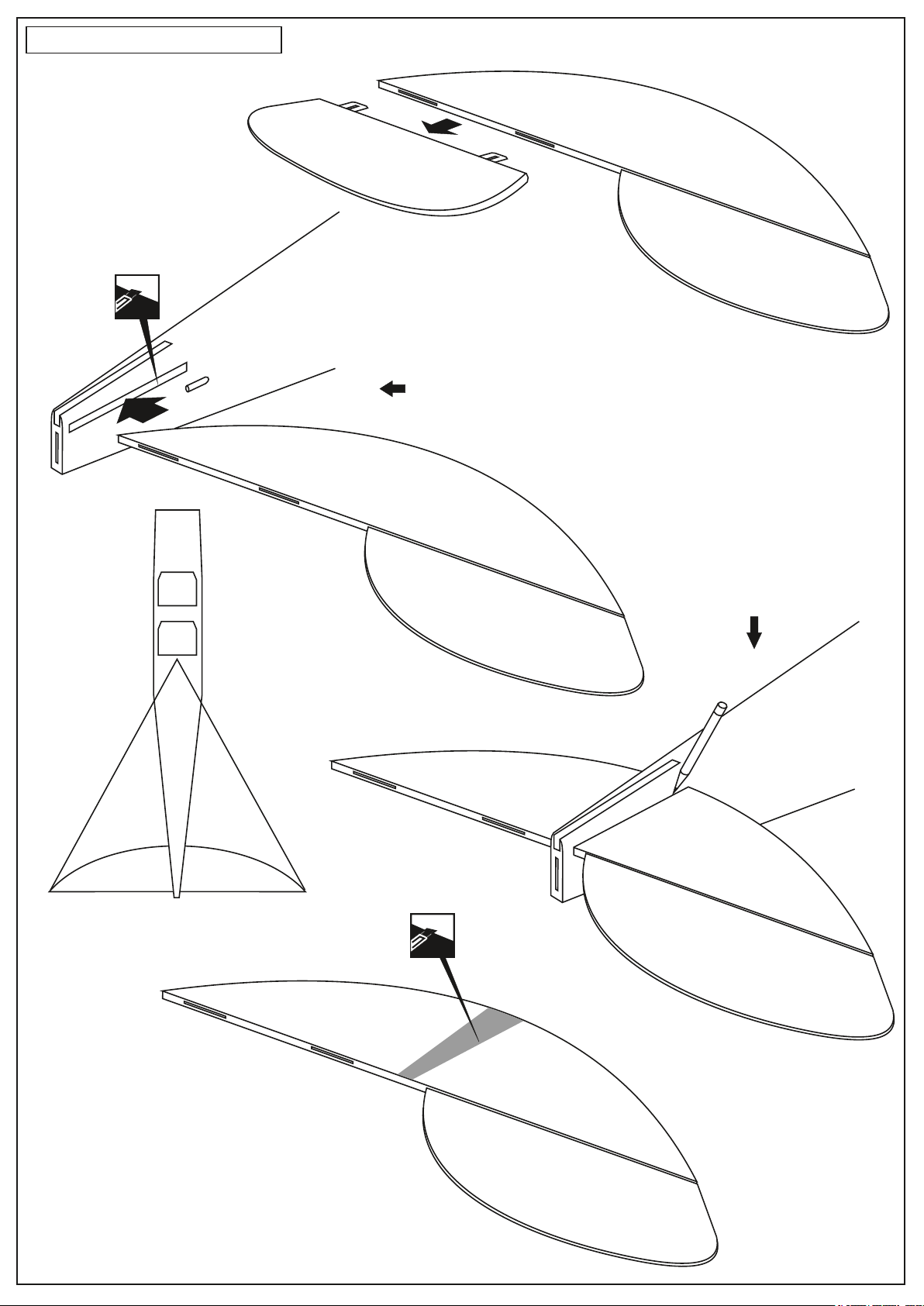
4- Horizontal Stabilizer
Full the elevator out of the
horizontal stabilizer.
Cut away only the
covering both side
4A
4B
Trial fit the horizontal stabilizer in place. Check the alignment of the
horizontal stabilizer.
If the parts will join, but with a gaps, sand or the rectangular hole on the
fuselage a little at a time until the parts meet exactly with no gaps.
A=A’
A
HORIZONTAL
STABILIZER
TOP VIEW
When you are satisfied with the alignment,
use a pencil to trace around the top and
bottom of the stabilizer where it meets the
fuselage.
A’
4C
Cut away only the
covering both side
4D
Remove the horizontal stabilizer from the fuselage.
Using the sharp hobby knife, carefully cut away the
covering inside the lines which were marked above.
* WARNING: When removing any covering from the airframe,
please ensure that you secure the cut edge with CA or similar
cement. This will ensure the covering remain tight.
Page 7
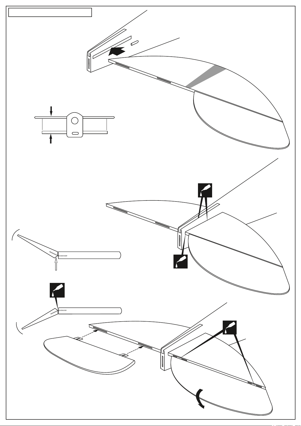
5- Horizontal Stabilizer
Horizontal stabilizer
Install the horizontal stabilizer into the fuselage
and adust the alignment as described in steep
4C.
5A
B
Aluminum tube
FRONT VIEW
TOP-SIDE
HORIZONTAL STABILIZER
Apply a thin layer of petroleum jelly
Apply thin CA glue on
the top (and bottom)
CA
of the hinge
TOP-SIDE
HORIZONTAL STABILIZER
B’
When you are satisfied with the alignment,
with the thin CA glue around the top and
bottom of the stabilizer where it meets the
fuselage and inside the slot on the top of
the fuselage.
B=B’
5B
Thin CA
! Securely glue together If coming
off during fly, you lose control of
your air plane.
CA
Thin CA
CA
CA
Apply thin CA
glue on the top
and bottom
of the hinge
5C
Without using glue yet, push the elevator and its
hinges into the hinge slots in trailing edge of the
horizontal stabilizer .
5D
Page 8
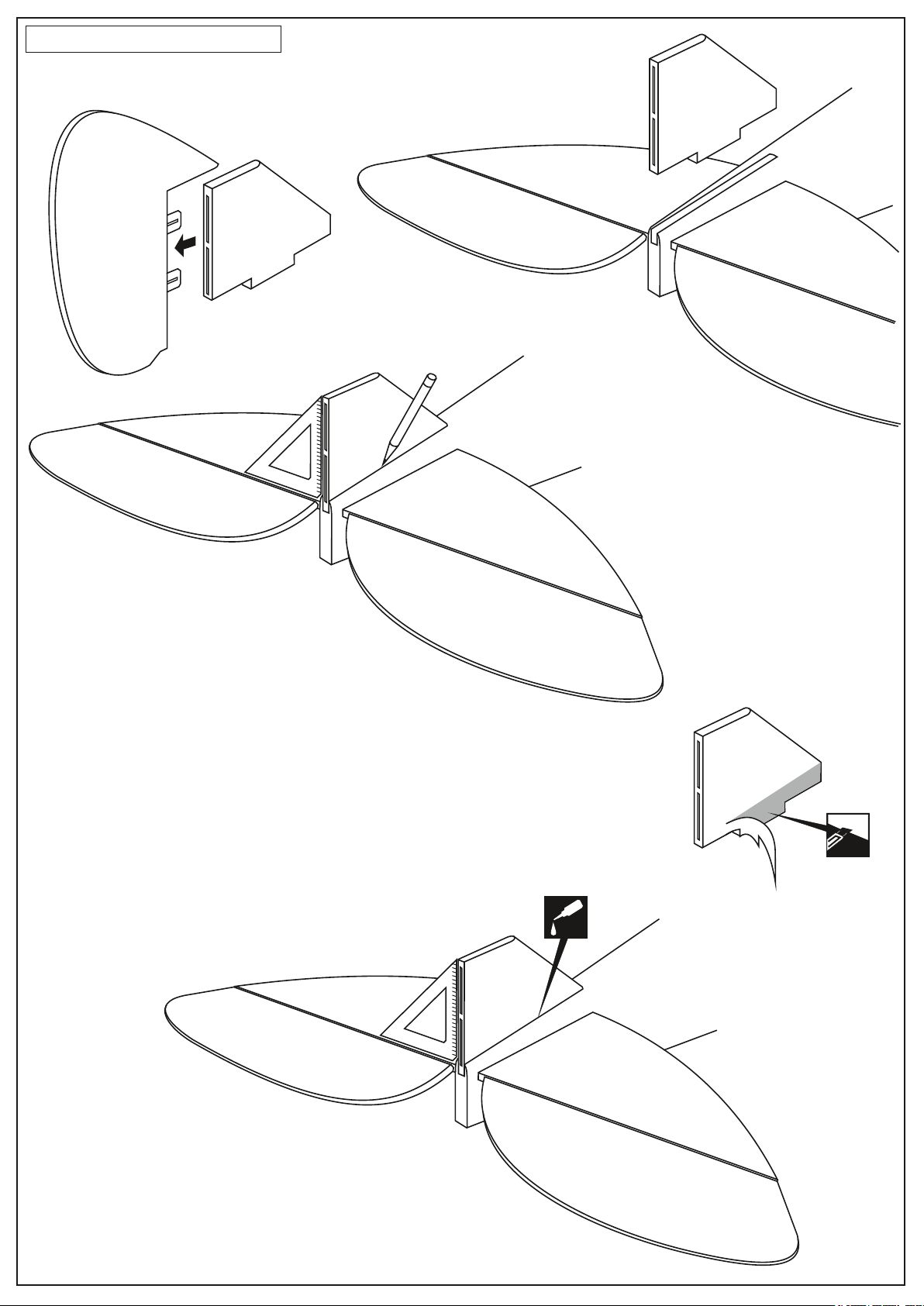
6- Vertical Stabilizer
Pull the rudder out of the vertical fin.
6A
Carefully, push the vertical fin into the
slot on the fuselage as shown .
6B
6C
Trial fit the vertical fin in position. Using
a 90 degree triangle, ensure that the
vertical stabilizer is perpendicular to the
horizontal stabilizer .
Using a pencil, trace around the vertical
stabilizer where it meets the fuselage.
Remove the vertical stabilizer from the
fuselage.
6D
Using s sharp hobby knife, carefully cut away the
covering below the lines which were drawn in the
previous steep. Do not cut into the woods as this
will affect the structural integrity of the stabilizer .
Cut away only
the covering
CA
6E
Insert the vertical fin into the fuselage, precisely align
the vertical stabilizer as described in step 6C.
Apply the thin CA glue on the vertical stabilizer where it
contacts the fuselage.
! Securely glue together. If coming off during fly,
you lose control of your air plane.
Page 9
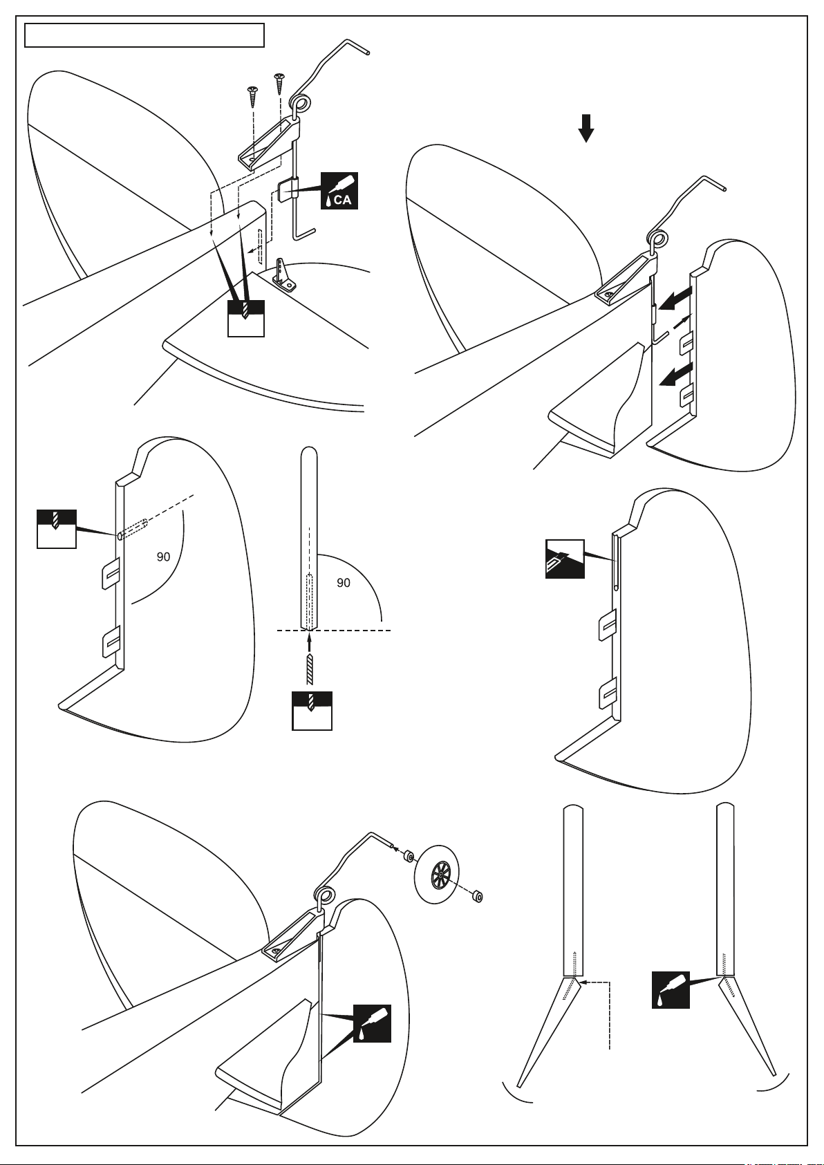
7- Tail wheel and Rudder
7A
1.5mm
Without using glue yet, push the rudder and its hinges into the hinge slots
in the trailing edge of the vertical stabilizer. There should be a minimal
hinge gap and the bottom edge of the rudder should not rub against the
vertical stabilizer.
When satisfied with the alignment, mark the mounting hole position, where
the tail gear torque rod meets the rudder with a pencil.
7B
RUDDER
1.5mm
o
o
7C
1.5mm
Remove the rudder and drill 1.5mm hole at the mark marked before.
Marking sure that you drill the hole perpendicular to the leading
edge of the rudder (7C).
Cut away the covering and
balsa for the tail gear torque
rod mounting slot (7D).
7D
TOP-VIEW
apply a thin CA glue on the
left and right of the hinge.
CA
7E
Apply a thin CA glue
VERTICAL STABILIZER
on the left and right of
the hinge.
CA
Apply a thin layer of
petroleum jelly
! Securely glue together. If coming off during fly, you lose
control of your air plane.
VERTICAL STABILIZER
Page 10
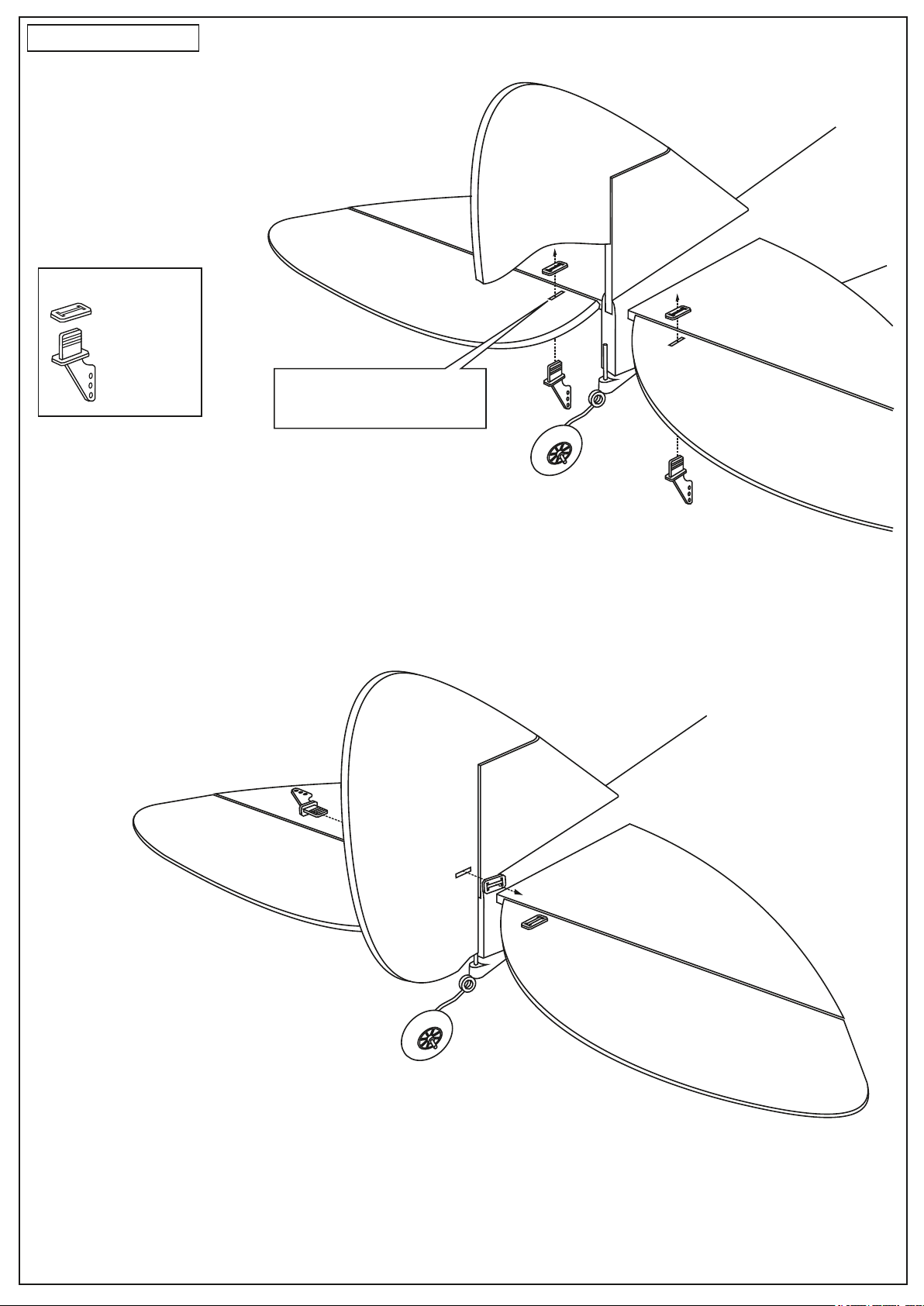
8- Control horn
Plastic control horn
...................3
Note: the rectangular holes for
the control horn installation
are pre-cut at factory.
8A
8B
Page 11
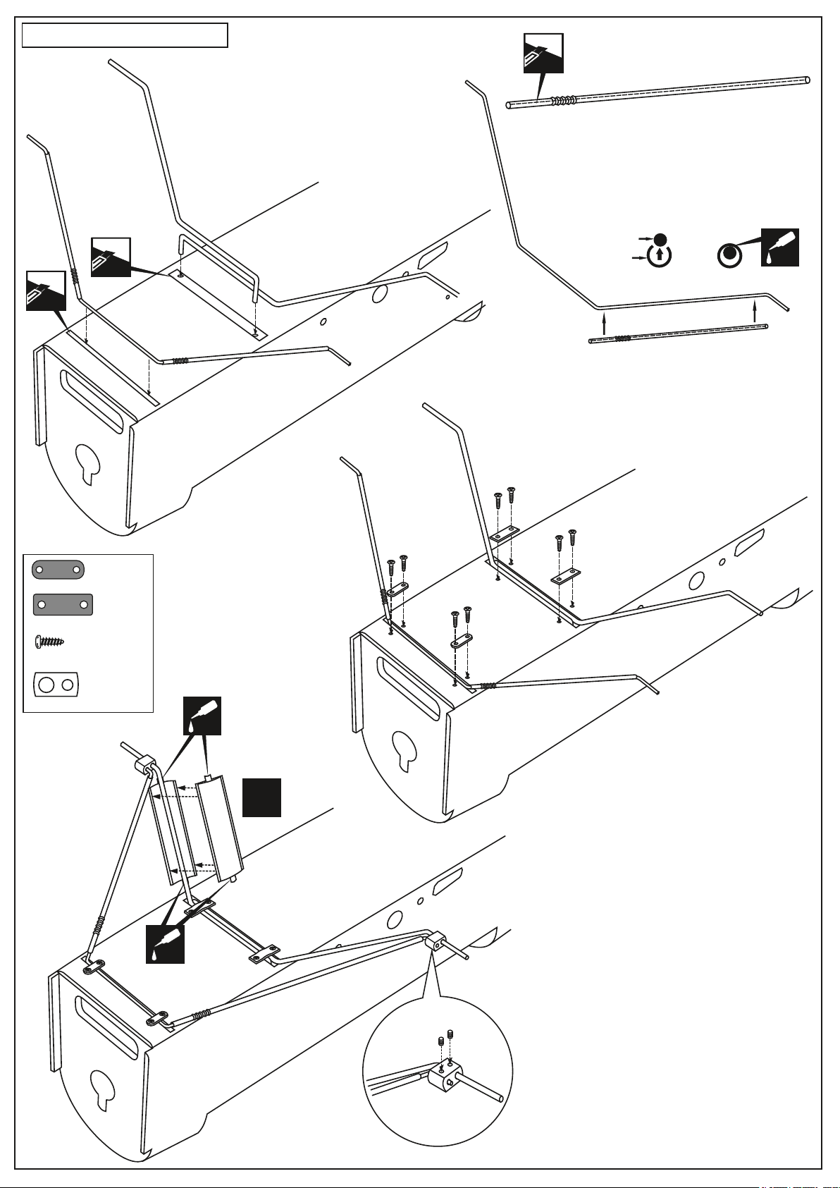
9- Main landing gear
* WARNING: When removing any covering from the
airframe, please ensure that you secure the cut edge
with CA or similar cement. This will ensure the covering
remain tight.
cut along the drinking straws
9A
cut away only
the covering
.....................2
9C
9D
3mm landing gear
Drinking straws
CA
9B
.....................2
3x10mm
.......................8
.............2
9E
CA
L/R
CA
Page 12
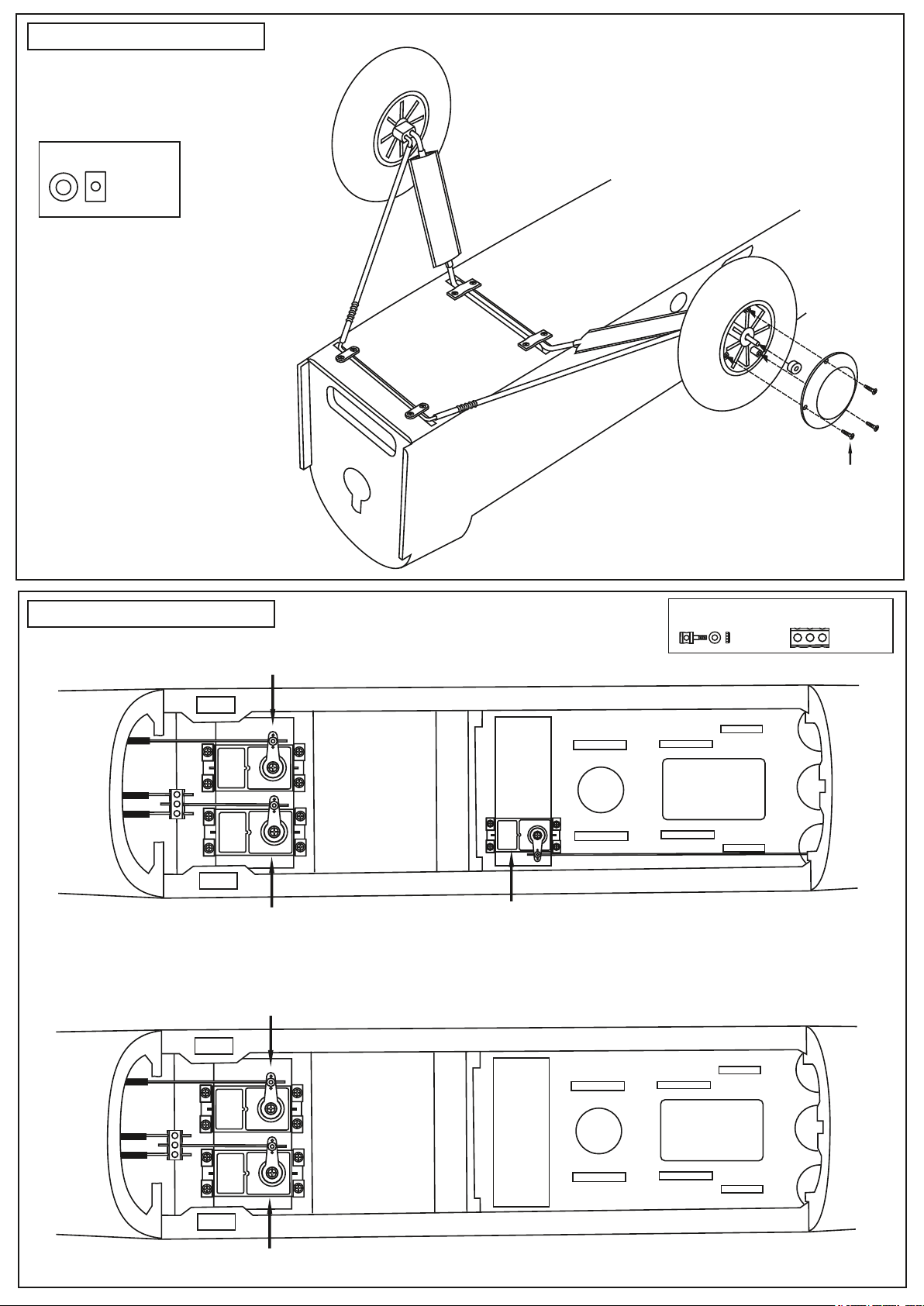
10- Main landing gear
2mm ID collar
....2
1.5mm screws set
11- Servo and linkages
Rudder servo
Elevator servo
Rudder servo
IN CASE OF GLOW ENGINE USING
Throttle servo
FUSELAGE - TOP VIEW
IN CASE OF ELECTRIC MOTOR USING
Connector
...2
Fuel tank
area
Connector
...1
Elevator servo
Li-po battery
area
FUSELAGE - TOP VIEW
Page 13
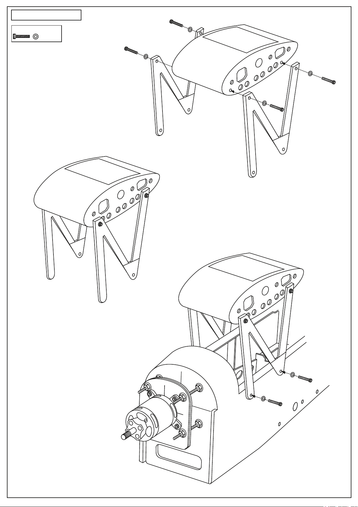
12- Wing Strut
3x25mm screw
..........8
12A
12B
12C
Page 14
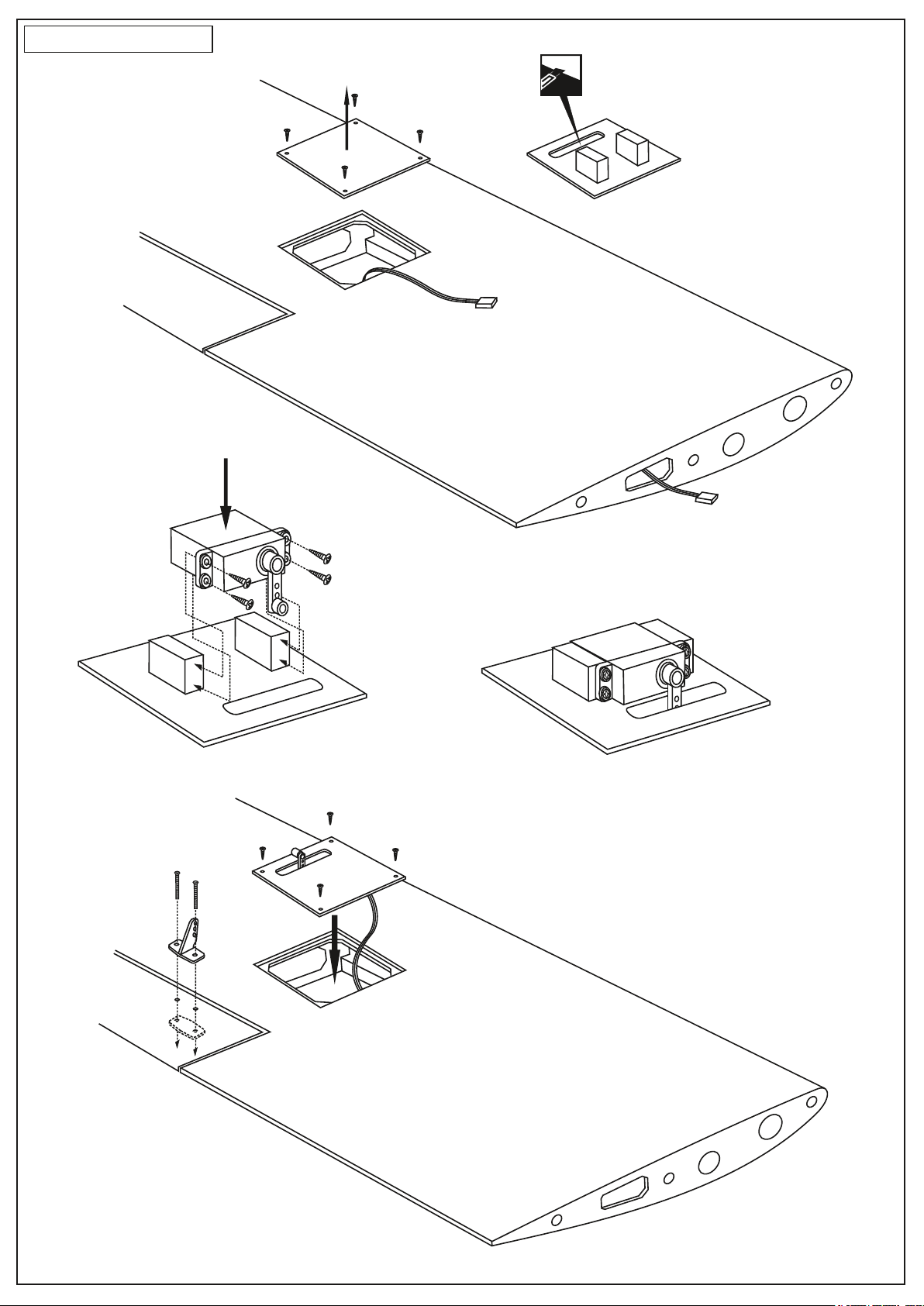
13- Aileron servo
Remove the aileron hatch
cut away the covering only
LOW WING - BOTTOM-VIEW
Page 15
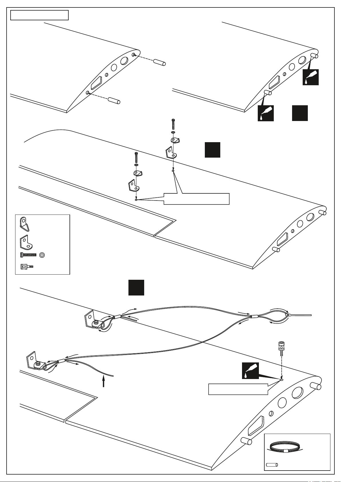
14- Low Wing
wooden dowel
...................4
...................4
13A
wooden dowel
13C
L/R
Two holes are ready mark
CA
thin CA
13B
CA
thin CA
TOP OF THE LOW-WING
L/R
..........4
...................2
L/R
13D
Do not cut the excess cable at this time.
CA
The hole is ready mark
TOP OF THE LOW-WING
0.5mm dia. x 180cm Cable
...1 roll
2mm metal tube
.....................6
Page 16
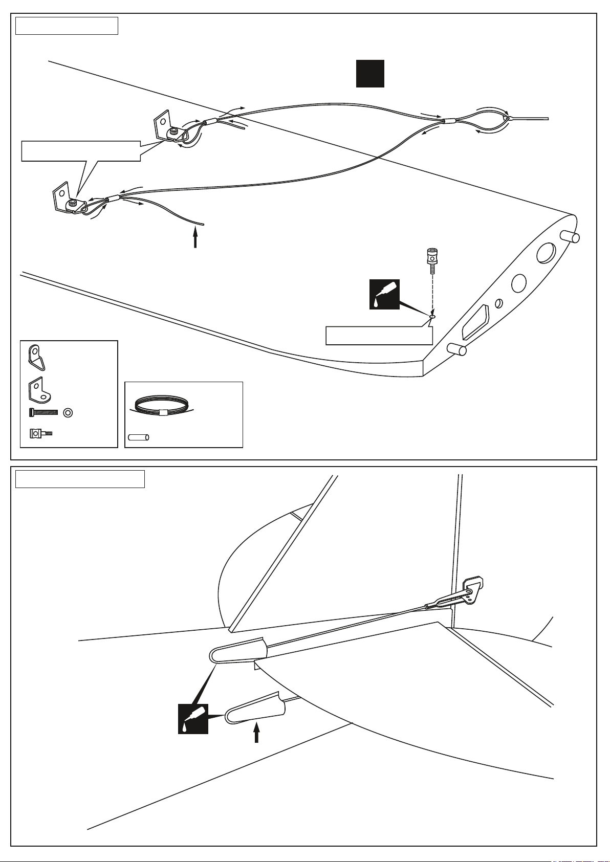
15- High Wing
Two holes are ready mark
Do not cut the excess cable at this time.
...................4
BOTTOM OF THE HIGH-WING
L/R
CA
The hole is ready mark
...................4
..........4
...................2
0.5mm dia. x 180cm Cable
2mm metal tube
16- Rod exit guide
...1 roll
.....................6
CA
Rod exit guide
Page 17
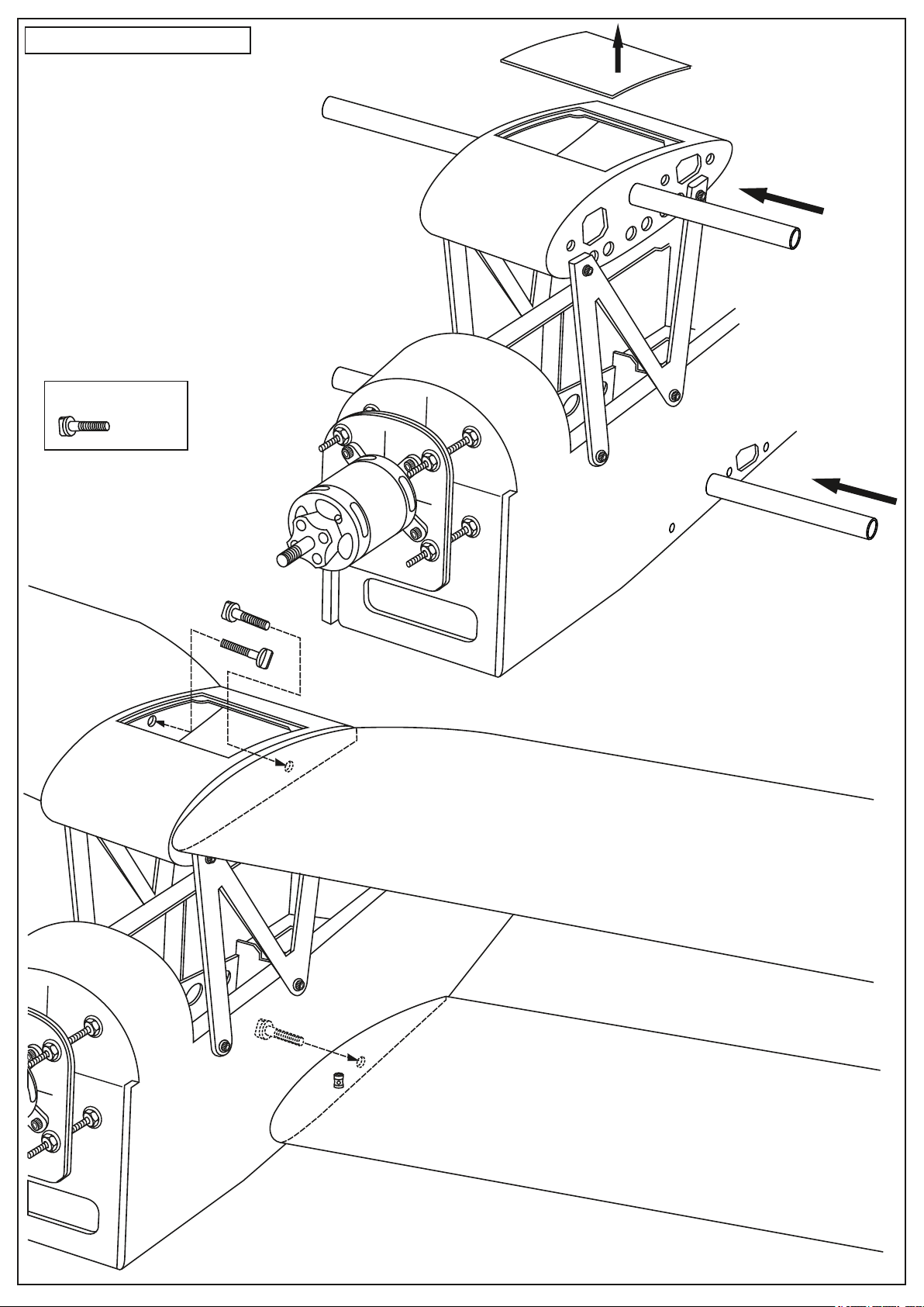
17- Wing installation
12x318mm aluminium tube
6x25mm nylon bolt
............4
Remove the magnetic hatch
6x25mm nylon bolt
12x318mm aluminium tube
6x25mm nylon bolt
Page 18
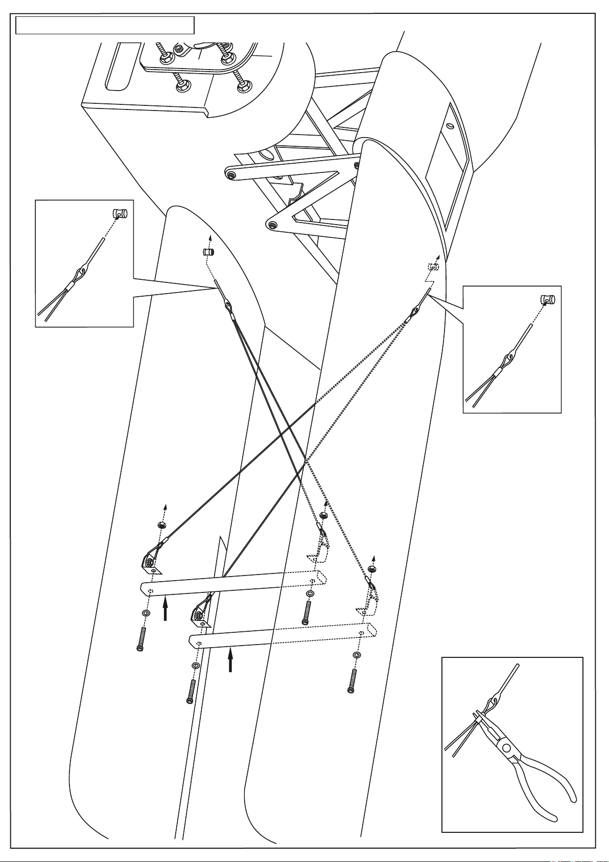
18- Cable and wing brace
Short brace
Long brace
Page 19
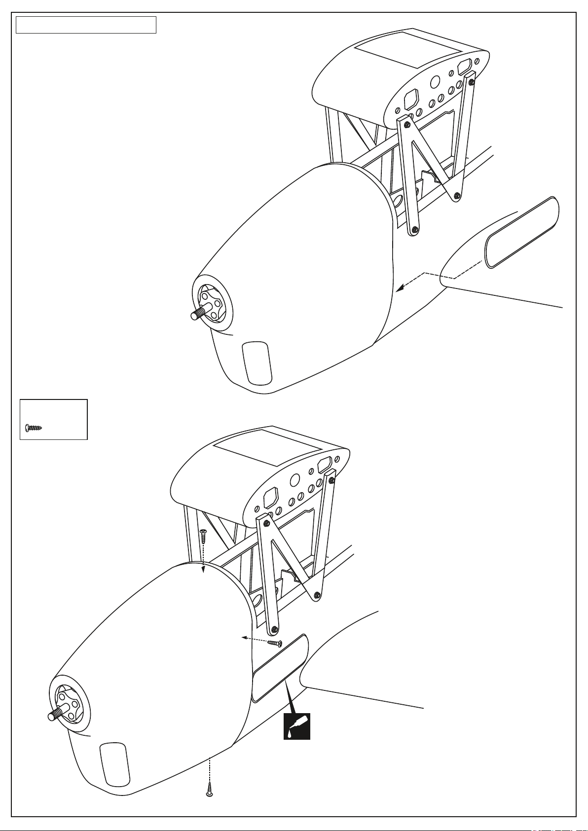
19- Fiberglass Cowl
........4
CA
Page 20
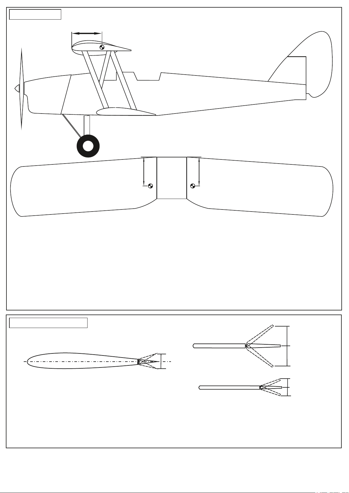
20- Balance
CG= 106 - 112mm
CG= 106 - 112mm
Der ideale Schwerpunkt befindet sich 106 - 112mm hinter der Nasenleiste
der oberen Tragfläche
THE CENTER OF GRAVITY IS LOCATED 106 - 112mm BACK FROM THE
LEADING EDGE OF THE UPPER WING, AT THE FUSELAGE.
1- Mount the wing to the fuselage. Using a couple of pieces of masking tape, place them
on the top side of the wing (110mm) back from the leading edge, at the fuselage sides.
2- Lift the airplane. Place your fingers on the masking tape and carefully lift the plane.
Obere TragflächeObere Tragfläche
UPPER WING
3- If the nose of the plane falls, the plane is heavy nose. To correct this, move the battery pack further back in the fuselage.
If the tail of plane falls, the plane is tail heavy. To correct this, move the battery forward or if this is not possible, stick weight onto the
firewall.
When balanced correctly, the airplane should level or slightly nose down when you lift it up with your fingers.
LATERAL BALANCE:
After you have balanced a plane on the CG, you should laterally balance it. Doing this will help the airplane track straighter.
1- Turn the airplane upside down. Attach one loop of heavy string to the engine crankshaft and one to the tail wheel wire.
With the wing level, carefully lift the airplane by the string. This may require two people to make easier.
2- If one side of the wing fall, that side is heavier than the opposite. Add small amounts of lead weight to the bottom side
of the lighter wing half’s wing tip. Follow this procedure until the wing stays level when you lift the airplane.
DO NOT try to fly an out-of-balance model !
UPPER WING
21- Control surface
Ruderausschläge
10mm
10mm
RUDDER
30mm
30mm
AILERON
ELEVATOR
IMPORTANT: Flying your model at these throws will provide you with the greatest chance for successful first flights.
If,after you have become accustomed to the way the P-51 flies, you would like to change the throws to suit your taste
that is fine. However, too much control throw could make the model difficult to control, so remember, “more is not always better”.
IMPORTANT: Please do not clean your model with strong solvent or pure alcohol, only use kerosene to keep the
colour of your model not fade.
10mm
10mm
 Loading...