

Page 1
Page 2
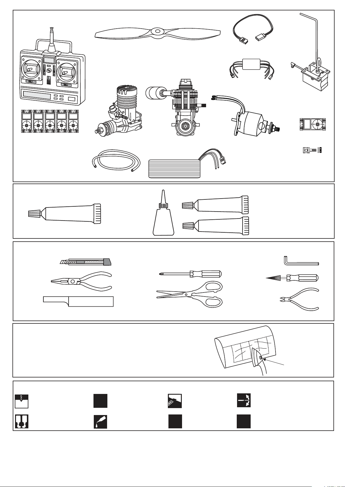
REQUIRED FOR OPERATION (Purchase separately)
Minimum 5 channel radio
for airplane with 5 servos
.Motor control x1
.Elevator x1
.Rudder x1
.Aileron x2
GLUE
(Purchase separately)
SILICON
Silicon sealer
10.5x6 for .40 - 2 cycle engine
11x6 for .46 - 2 cycle engine
12x6 for .60 - 4 cycle engine
12x7 for .70 - 4 cycle engine
13x8 for G-46 HP Motor.
.46 ~ .50 - 2 cycle
Silicone tube
Cyanoacrylate
Glue
.60 ~.70 - 4 cycle
CA
Extension for aileron
servo, retract servo.
Motor Control
G-46 HP Motor
or equivalent.
Li-Po Battery, 5 cell 4500mAh.
Epoxy Glue ( 5 minute type)
EPOXY A
Epoxy Glue (30 minute type)
EPOXY B
Retract landing
gear
VQAR03
16023
Retract servo
x1
Linkage Stopper x2
(for retract servo)
TOLLS REQUIRED
Hobby knife
(Purchase separately)
Phillip screw driver
Needle nose Pliers
Scissors
Sander
.........................................................
.........................................................
.........................................................
.........................................................
.........................................................
.........................................................
.........................................................
.........................................................
.........................................................
.........................................................
.........................................................
Masking tape - Straight Edged Ruler - Pen or pencil - Rubbing alcohol - Drill and Assorted Drill Bits
The pre-covered film on ARF kit may wrinkle due to variations
of temperature. Smooth out as explained right.
* Use an iron or heat gun. Start as low setting. Increase the
setting if necsessary. If it is too high, you may damage the
film
Symbols used throughout this instruction manual, comprise:
Drill holes using the stated
1.5mm
size of drill
(in this case 1.5 mm Ø)
A
B
Use epoxy glue
Take particular care here
!
Apply cyano glue
CA
Hatched-in areas:
remove covering
film carefully
Assemble left and right
L/R
sides the same way.
Hex Wrench
Awl
Wire Cutters
Low setting
Check during assembly that these
parts move freely, without binding
Not included.
These parts must be
X
purchased separately
Read through the manual before you begin, so you will have an overall idea of what to do.
CONVERSION TABLE
1.0mm = 3/64”
1.5mm = 1/16”
2.0mm = 5/64”
2.5mm = 3/32”
3.0mm = 1/8”
4.0mm = 5/32”
5.0mm = 13/64”
6.0mm = 15/64”
10mm = 13/32”
12mm = 15/32”
15mm = 19/32”
20mm = 51/64”
25mm = 1”
30mm = 1-3/16”
45mm = 1-51/64”
Page 3
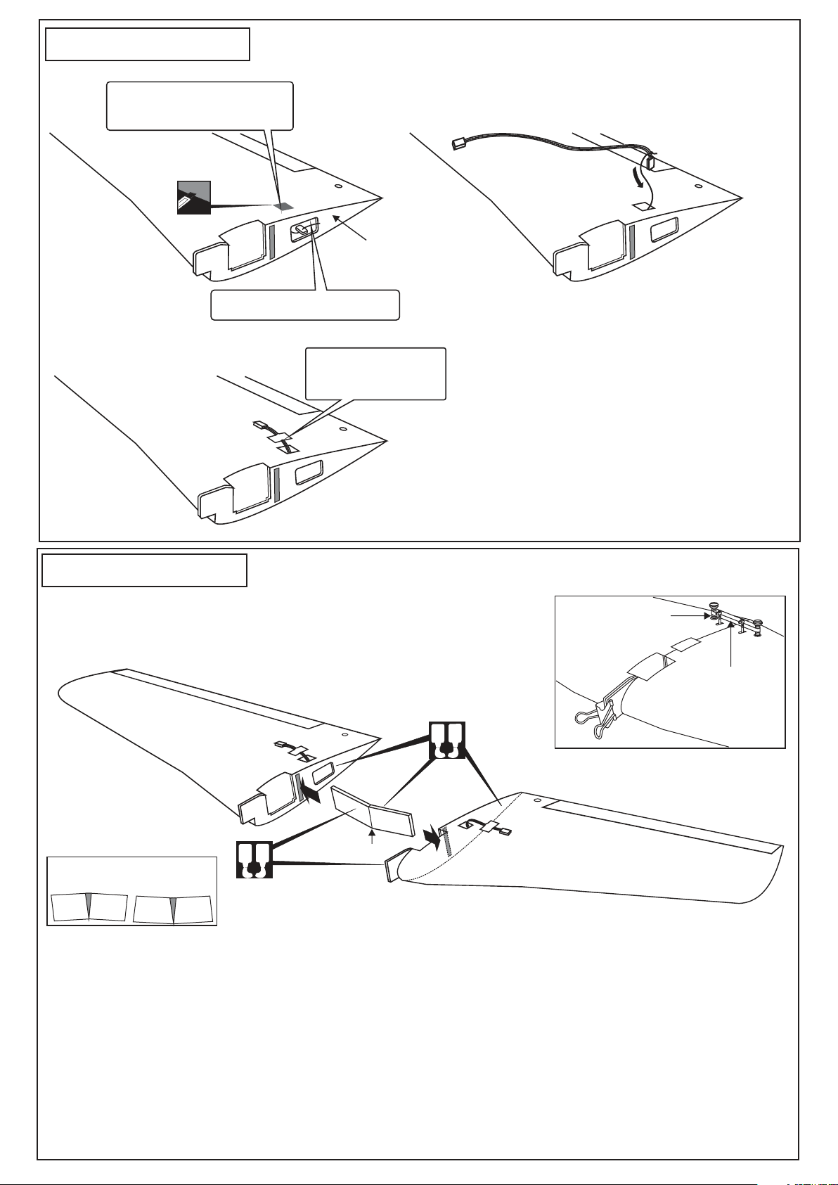
1- Joining the wing
Cut the opening hole (½”x1/2”)
throughout the balsa wood for
the aileron extension cord exit.
Thread (pre-installed at factory)
WING - TOP VIEW
WING ROOT
Using the thread (pre-installed at factory) to slide
the aileron extension cord into the wing half.
Secure one end of the
aileron extension cord
with adhesive tape
Do the same way with other wing half.
2- Joining the wing
Note: The two wing halves roots must fit together perfectly.
! Make sure to glue securely, If not properly glued, a failure
in flight may occur.
Center line
TOP VIEW
Use epoxy glue to bury the
opening
A
B
A
B
Hold the wing halves together with binder
clip and rubber band (not include)
Nylon wing bolt
Rubber band
(both the top
and bottom)
Binder clip
1- Using a pencil, mark the center of the brace.
2- Trial fit the wing joiner into one of the wing panels. It should insert smoothly up to the center line marked above.
3- Slide the other wing half onto the dihedral brace until the wing panel meet. If the fit is over tight, it may be necessary to
lightly sand the dihedral brace.
4- Check for the correct dihedral angle.
5- Mix up some 30 minute epoxy and apply a generous amount of epoxy into the wing joiner cavity of one wing half.
6- Coat one half of the dihedral brace with epoxy up to the center line. Install the epoxy-coated side of the dihedral brace
into the wing joiner cavity up to the center line, marking sure that the “V” of the dihedral brace is positioned correctly
7- Do the same way with the other wing half.
8- Carefully slide the wing halves together, ensuring that they are accurately aligned. Firmly press the two halves
together, allowing the excess epoxy to run out. Clean off the excess epoxy.
Please do not clean off the excess epoxy on the wing with strong solvent or pure alcohol, only use
IMPORTANT:
kerosene to keep the colour of your model not fade.
Page 4
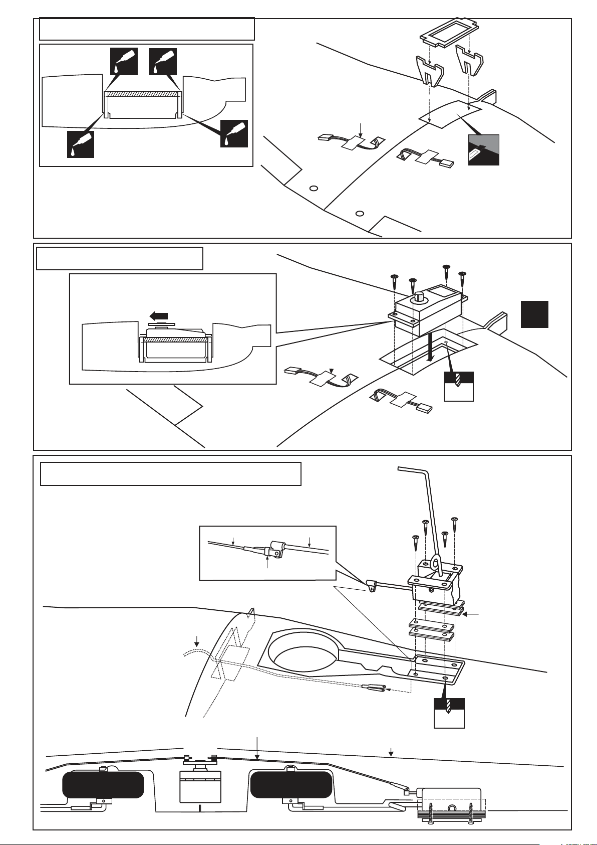
3- Retract servo tray
CENTER
WING
SECTION
CA
B
CA
A
C
TOP VIEW
Retract servo
mount
Secure one end of the
aileron extension cord
with adhesive tape
B
Retract servo tray
A
1/8(3mm plywood)
Retract servo
C
mount
BOTTOM
CA
Retract servo tray installation
4- Servo Installation
RETRACT SERVO INSTALLATION
Note: The head of servo should be positioned
toward the rear of the wing.
CENTER
WING
SECTION
BOTTOM
CA
TOP VIEW
Cut away only
the covering
Retract landing gear
servo
1/16”
1.5mm
X
5- Retract landing gear installation
Trial fit the push rod into the wing. Join the pushrod to the retract
gear arm and trial fit the retract into the wing.
After checking that the retract works
smoothly, fix the retract on the wing
with 3x20mm self tapping screws.
Do the same way with other half wing.
Retract pushrod
Retract push rod Retract gear arm
Put the nylon ring
BOTTOM-VIEW
Retract pushrod
FRONT-VIEW
Install the retract servo onto the retract servo mount
and secure it in place with four screw (included with radio set).
3x20mm screw
(not included)
VQ-AR03 -160223
Retract (option)
Plywood buffer
included with
retract set.
2mm
WING-TOP
RETRACT
SERVO
VQ-AR03 -160223
Retract (option)
Page 5
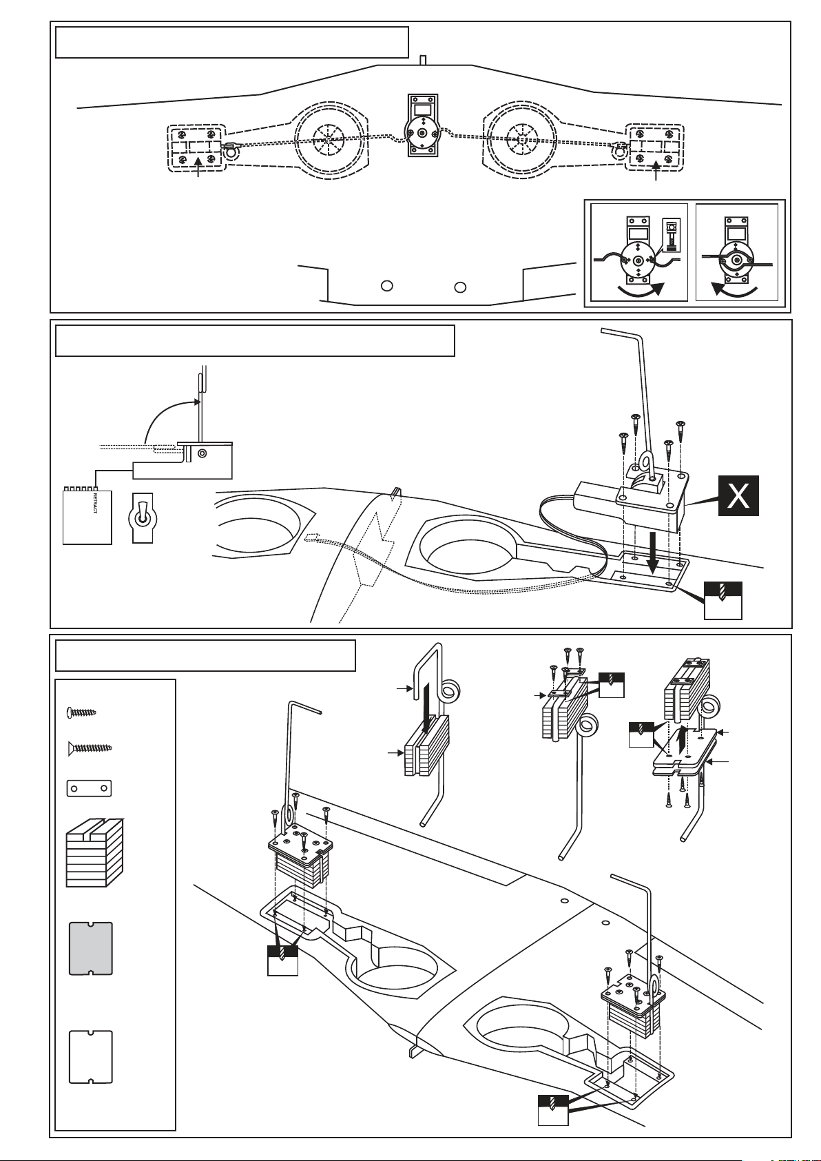
6- Retract landing gear Installation
Link the servo and retract gear arm with push rod.
Be sure to adjust the stroke so that the landing
gear locks in both up and down position.
Retract servo
Retract gear
WING TOP-VIEW
With the retract and retract servo in the
retracted position, mark the position where
each of the pushrod will attach to the servo
arm, a small piece of masking tape works
well for this. Cut off the excess length each rod.
7- Electric retract landing gear / Einziehfahrwerk
EXTENDED POSITION
RETRACTED POSITION
ON
RECEIVER
OFF
GEAR
ELECTRIC RETRACT
LANDING GEAR
RETRACTED
ELECTRIC RETRACT
LANDING GEAR
Retract gear
EXTENDED
8- Fixed gear / Starres Fahrwerk
3x12mm screw
..........8
3x20mm screw
......16
Nylon gear strap
.......4
3x12mm screw
Gear mount x 2
Ply gear mount
plate x 2
Main landing gear
2mm
Gear mount
Bottom view /Ansicht von unten
3x20mm
Nylon gear
strap
1
2
3x20mm screw
2mm
2mm
3x20mm
2mm
Ply gear
mount flat
Square
plastic
3
Square plastic x 2
4
Wing - bottom view
2mm
Page 6
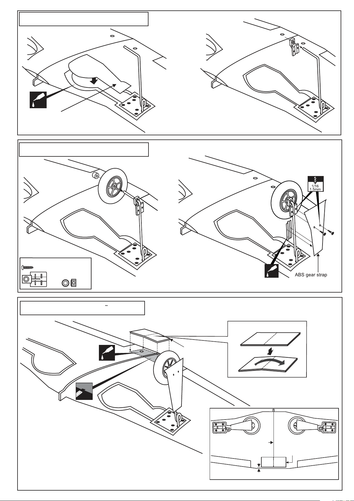
9- Fixed gear / Starres Fahrwerk
CA
ABS Wheel well cover
10- Fixed gear / Starres Fahrwerk
Bottom view /Ansicht von unten
2x6mm screw
..........4
4mm collar
...2
11- Wing bolt flat /
....2
Verstarkung
Wing bolt flat
CA
Cut away only the
covering
Bottom view /Ansicht von unten
Using the wing bolt flat as a
template, trace around the outside
edge of the wing bolt flat and then remove it.
Using a sharp hobby knife, cut away the covering inside the lines. Not
to cut into the wood.
Apply the wing bolt flat in place and secure it with CA glue.
CA
Wing bolt flat 1/8”(3mm)plywood
Center line
Wing bolt flat
5/32” (4mm)
Page 7
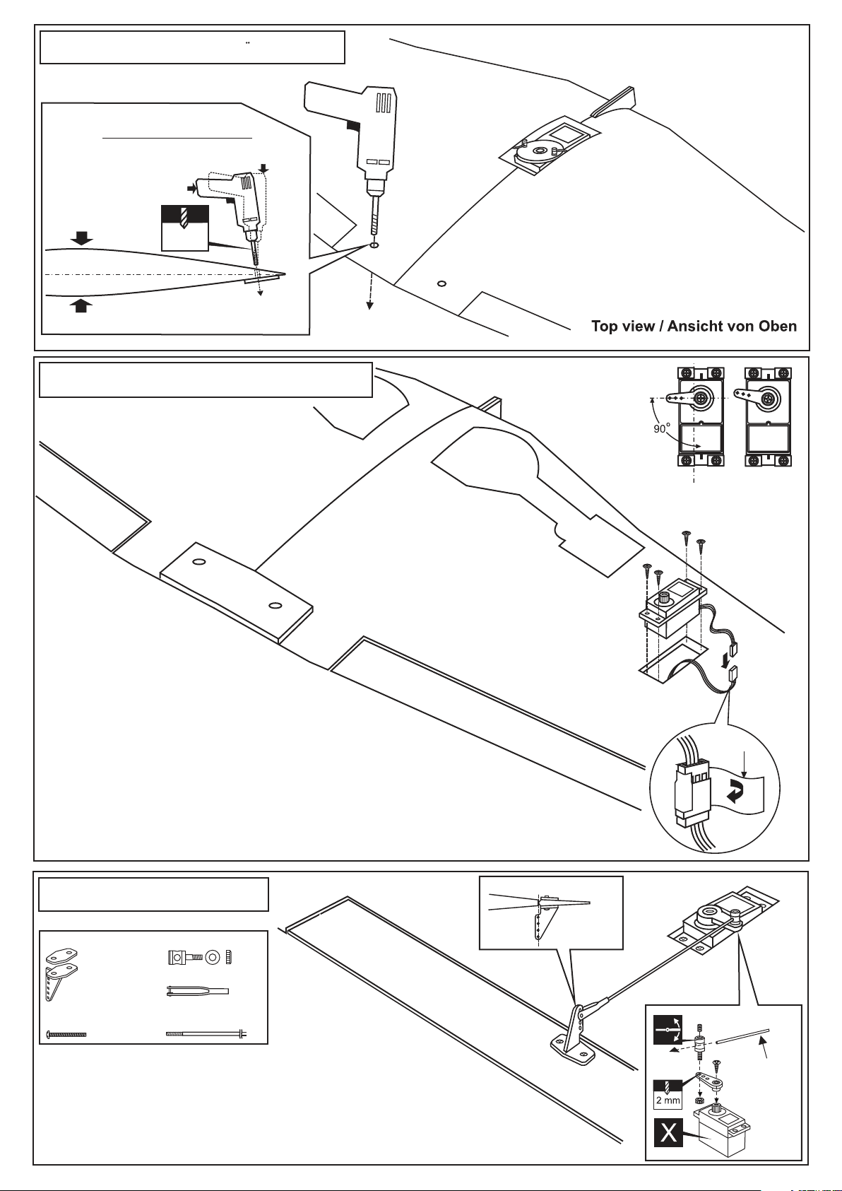
12- Wing bolt flat / Verstarkung
Drill the holes throughout the wing
bolt plat , from the top to the bottom
of the wing.
RIGHT
WRONG
TOP
17/64”
6.5mm
WING
BOTTOM
13- Aileron servo installation
-Switch on the radio (trims centered)
then mount the ailerons servo horn in
neutral position.
-The servo horn should
be perpendicular to
the servo
YES
NO
BOTTOM VIEW
Connect the aileron extension cord to the
aileron servo and secure with adhesive tape
before install the aileron servo on to the wing.
Do the same way with second aileron servo.
14- Aileron linkage
Plastic control horn
....................2
2x20mm screw
..............4
Depending on the position of the linkage, determine the location
of aileron control horn.
The horn holes must be perfectly aligned with the axis of articulation.
Mark the position of the “foot” of the horn on the aileron. Then, with
the drill, make the 2 holes.
Install the aileron control horn as shown.
Connector
......2
......2
Aileron push rod
..2
AILERON
WING BOTTOM-VIEW
Adhesive
tape
Hinge Line/Control horn Alignment
2mm screw
Aileron pushrod
Page 8
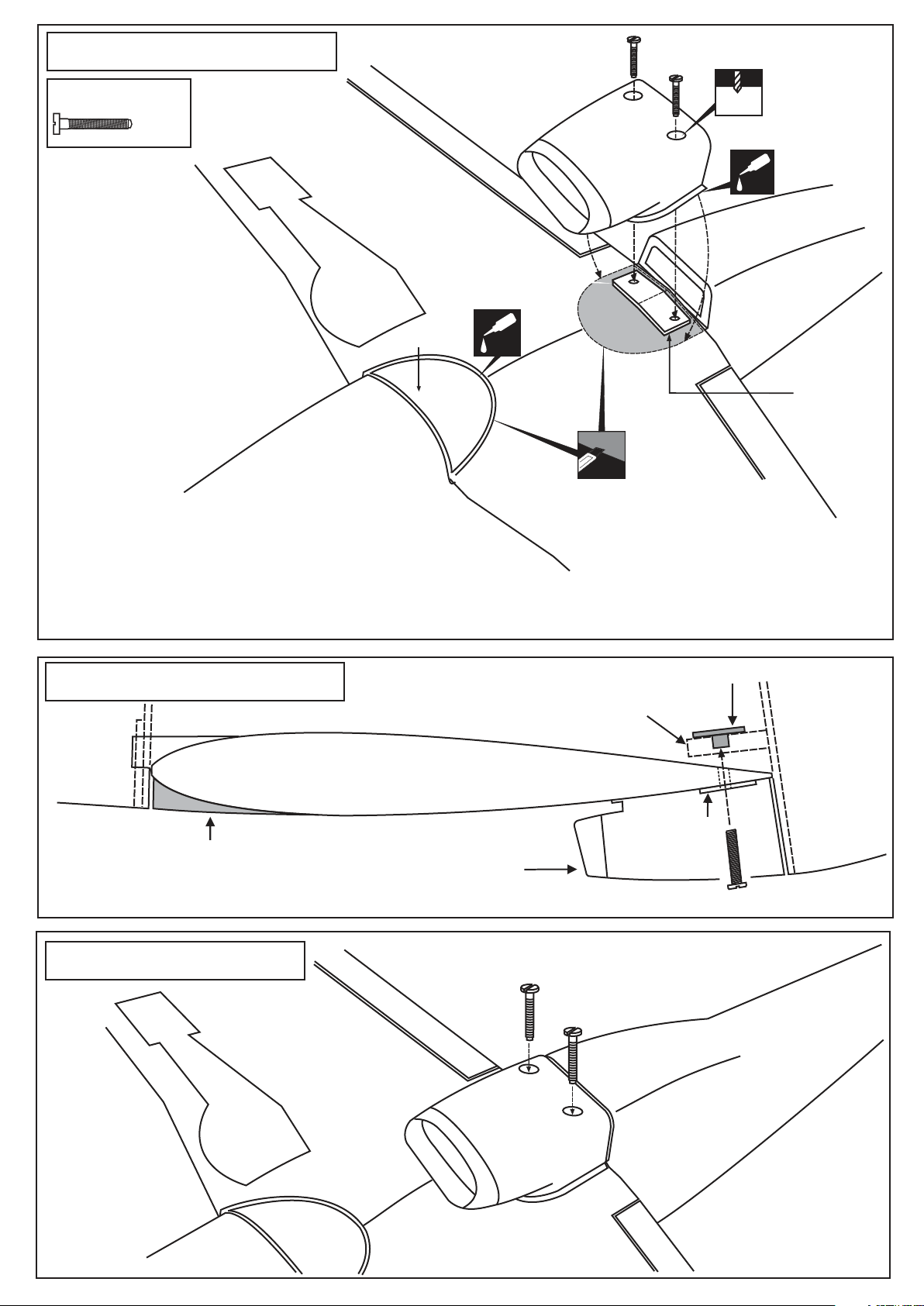
15- Air Scoop/wing cover
6x40mm nylon bolt
.........2
Wing cover
BOTTOM-VIEW
Plastic air scoop
CA
Cut away the covering inside the line
before install the air scoop and wing cover
15/32”
12mm
CA
Wing bolt plat
1/8”(3mm) ply
1-Using the ABS air scoop as a template, trace around the outside edge of the ABS air-scoop,and then remove it.
2-Using a sharp hobby knife, cut away the covering inside the lines. Not to cut into the wood.
3-Apply the ABS air scoop in place and secure with CA glue. Do the same way with the ABS wing cover.
16- Air Scoop/wing cover
Wing bolt mount
(Ply wood)
Plastic mount nut
WING
Bottom
Plastic cover
Plastic air scoop
Wing bolt plat
6x40 plastic bolt
17- Installing the wing
Nylon wing bolt
BOTTOM-VIEW
Page 9
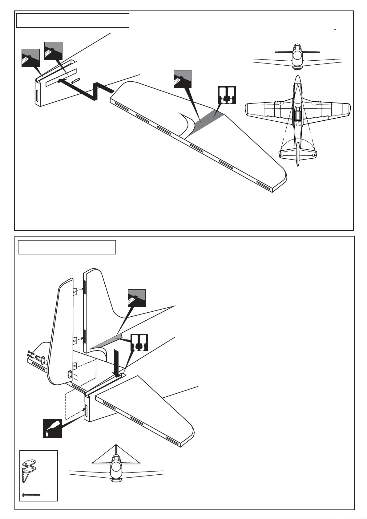
18- Horizontal stabilizer
Cut away only the covering both
the right and left side
Securely glue together. If coming off during flight, you lose control of
your air plane.
Vergewissern Sie sich, sauber geklebt zu haben. Andernfalls konnen
Probleme mit der Flugeigenschaft auftreten!
Cut away only the covering
both the top and bottom side*
Both the top and
bottom side
A
B
1-Trial fit the horizontal stabilizer in place .
Check the alignment of the horizontal
stabilizer. When you are satisfied with the
alignment, use a pencil to trace around the top and
bottom of the stabilizer where it meets the fuselage.
2-Remove the horizontal stabilizer from the fuselage. Using the
sharp hobby knife, carefully cut away the covering inside the
lines which were marked above.
3-Spread epoxy (30 minute) onto the top and bottom of the horizontal stabilizer
along the area where the covering was removed and to the fuselage where the
horizontal stabilizer mounts.
4-Install the horizontal stabilizer into the fuselage and adust the alignment as described in steep 1
5-Wipe off any excess epoxy using a paper towel and rubbing alcohol.
Allow the epoxy to cure before proceeding to next step.
* WARNING: When removing any covering from the airframe, please ensure that you secure the
cut edge with CA or similar cement. This will ensure the covering remain tight.
B
A
90O90
B’
A = A’
B = B’
A’
O
19- Vertical stabilizer
CA
Thin CA
Control horn
...........1
C = C’
C
Cut away only the covering both
the right and left side*
Both the left and
right side
A
B
Please do not clean off the excess epoxy
with strong solvent or pure alcohol, only use kerosene to
keep the colour of your model not fade.
C’
1-Trial fit the vertical stabilizer in place . Check the
alignment of the vertical stabilizer. When you are
satisfied with the alignment, use a pencil to trace
around the right and left of the stabilizer where it
meets the fuselage.
2-Remove the vertical stabilizer from the fuselage.
Using the sharp hobby knife, carefully cut away the
covering inside the lines which were marked above.
3-Spread epoxy (30 minute) onto the right and left and
bottom of the vertical stabilizer along the area where
the covering was removed and to the fuselage where
the vertical stabilizer mounts.
4-Install the vertical stabilizer into the fuselage and
adust the alignment as described in steep 1.
Allow the epoxy to cure before proceeding to next step.
IMPORTANT:
5-Push the rudder and its hinges into the hinge slots in
the trailing edge of the vertical stabilizer. There
should be a minimal hinge gap.
When satisfied with the and alignment, hinge the
rudder to the vertical stabilizer using thin CA glue.
Make sure to apply a thin CA glue to the left and right
of both hinges and to inside the hinge slots.
Securely glue together. If coming off during flight,
you lose control of your air plane.
2x12mm
......2
* WARNING: When removing any covering from the airframe, please ensure that you secure the cut edge with
CA or similar cement. This will ensure the covering remain tight.
Page 10
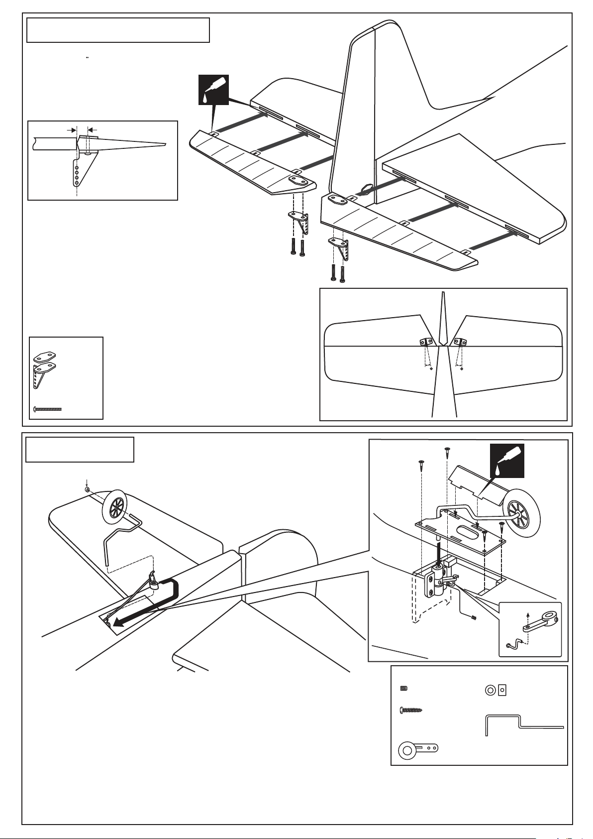
20- Elevator installation
Vergewissern Sie sich, sauber geklebt zu haben.
Andernfalls konnen Probleme mit der Flugeigenschaft
auftreten!
Securely glue together. If coming
off during flight, you lose control
of your air plane.
3/8 in. (9.5mm)
push the elevator and its hinges into the hinge slots in
the trailing edge of the horizontal stabilizer. There
should be a minimal hinge gap.
When satisfied with the and alignment, hinge the elevator
to the horizontal stabilizer using thin CA glue. Make
sure to apply a thin CA glue to the top and bottom of both
hinges and to inside the hinge slots. Repeat the previous
procedures to hinge the second elevator to the other side
of the horizontal stabilizer.
CA
Control horn
................2
2x12mm screw
..........4
21- Tail gear
5/64 in.(2mm) I.D collar
3
2
BOTTOM-VIEW
2x10mm
screw
5 5
H
Bottom view
6
D
4
CA
5
1
2x3mm screw
1- Insert the tail wheel pushrod into the hole on the tail gear control
horn (as show).
2- Install the tail wheel control horn in place.
3- Instal the tail wheel gear in place.
4- Secure the tail wheel control horn in place using a 5/64”(2mm) screw set,
Ensure smooth non-binding movement.
5- Installing the tail wheel hatch (H) in place using a four 5/64x25/64”(2x10mm) self tapping screws.
6- Attach the tail wheel doors (D) in place using CA glue.
2x10mm screw
Tail wheel controlhorn
............1
............4
.................1
2mm I.D collar
...............1
Tail landing gear
..........1
Page 11
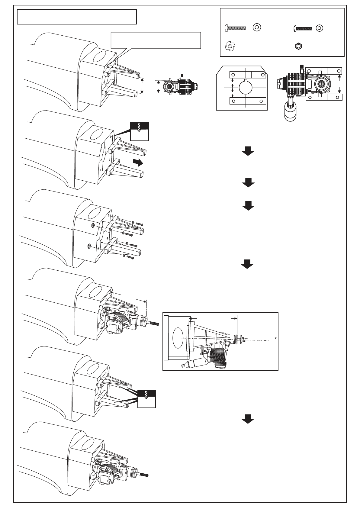
22- Engine mount - engine
5/32x1”
4x25mm screw
...4
1/8x5-1/64”
3x20mm screw
...4
! Align the mark on both mounts
with the mark on the fuselage
A
A
13/64”
5mm
- Using a pencil or felt tipped pen, mark the fire wall where the four
holes are to be drilled
- Remove the engine mount and drill a 13/64”(5mm) hole through
the fire-wall at each of the four marks marked.
Blind-nut
.................4
B
B’
B=B’
1/8”(3mm) nut
.................4
A
FRONT-VIEW
5-1/8”
- Reposition the engine mounts on to the fire-wall.
Attach the four blind-nut to the fire-wall as show.
Secure them with four 4x25mm screw.
- Position the engine on to the engine mounts so the distance
from the prop hub to the fire wall is 5-1/8”(127mm)
- Mark the engine mounting plate where the four holes are to be
drilled.
Note: Mark the mounting plate through the engine mounting flanges.
125~127mm
(5-1/8”)
TOP-VIEW
1.5
! Engine thrust on balk
head is already adjust
at factory
- Remove the engine and drill a 1/8”(3mm) holes through the beam
at each of the four marks made above.
1/8”
3mm
- Reposition the engine on the engine mount beams, aligning it with
the holes. Secure the engine to the engine mount using four
1/8x51/64”(3x25mm) screws.
Note: Apply Silicon sealer to
each of the 1/8x51/64” screw.
Page 12
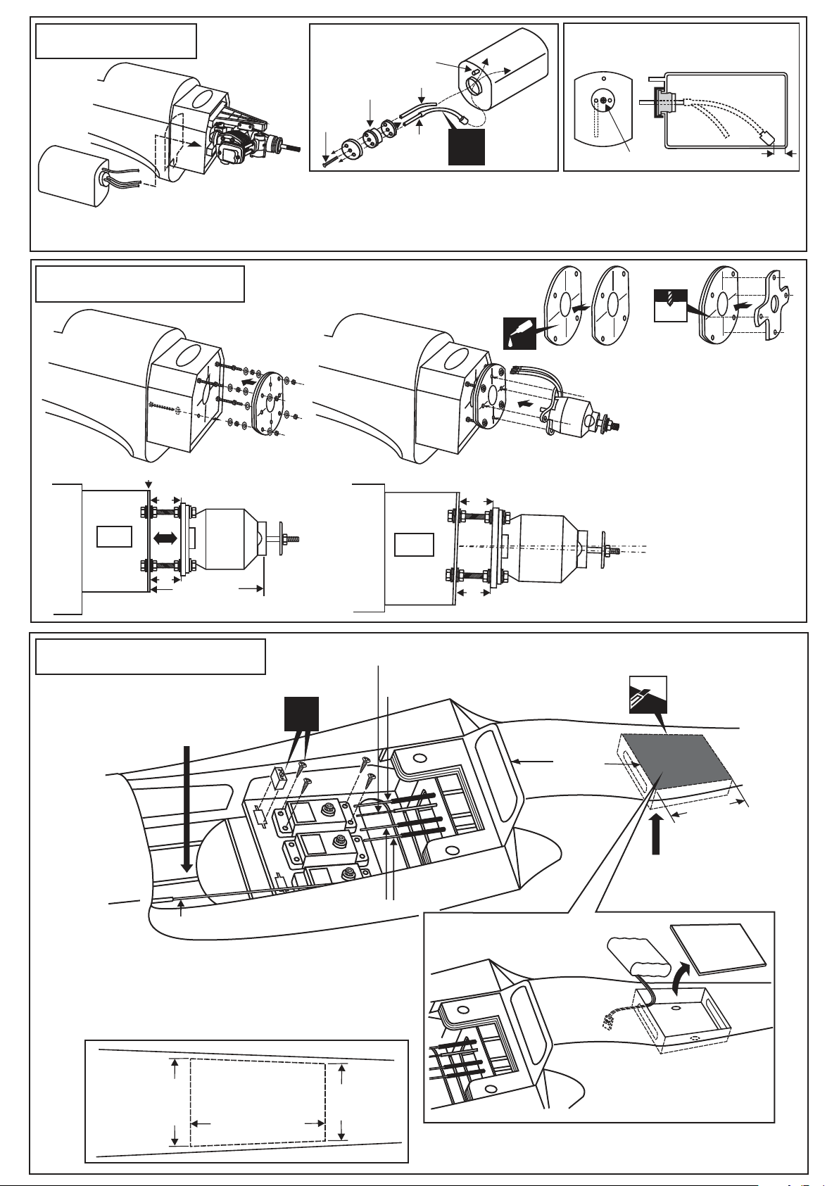
23- Fuel tank
1
Rubber stopper
3x25mm
screw
To muffler
Filler tube
To engine
X
2
3x35 mm screw
After confirming the direction . Insert this assembly, clunk end first, into the fuel
tank and tighten and screw the fuel tank cap on firmly.
Checking for leaks - block the vents and blow into the feed - if in doubt submersing the tank in a blow of water will
show up any problems
24- Electric motor
3mm
4mm
3
Firewall
B=B’
SIDE-VIEW
B
B’
125~127mm
(5-1/8”)
25- Radio and battery
Battery area
(in case of 2T engine)
Tail wheel push rod
Rudder push rod
X
A=A’
CA
1
4
TOP-VIEW
A
A’
! Engine thrust on balk head
is already adjust at factory
BOTTOM VIEW
2
Using a aluminum motor mounting
plate as a template, mark the
plywood motor mounting plate
where the four holes are to be
drilled (2).
Remove the aluminum
motor mounting plate and
drill a 1/8”(3mm) hole
through the plywood at
each of the four marks
marked .
Note: The aluminum motor mounting
included with electric motor set.
4-49/64”
(120mm)
2-61/64”
(75mm)
Battery area
(in case of 4T engine)
Elevator push rod
Throttle push rod
800-1000mah, flat pack
Carefully cut a 2-9/32”(58mm) wide area which is 2-61/64”
(75mm) in length through both the covering and the balsa
wood. Remove the excess balsa.
Put the battery pack into the box (pre-build at factory) and
fasten down with rubber bands or similar, ensuring it will not
come loose or rattle during flights.
2-9/32”
(58mm)
FUSELAGE
BOTTOM
Link the battery wire with the battery extension cord.
Reposition the hatch in place and secure it with CA glue.
Hatch
2-61/64”(75mm)
2”(51mm)
BOTTOM VIEW
Hatch
Page 13
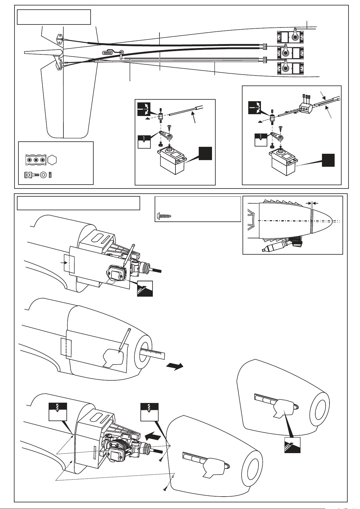
26- Linkages
Elevator push rod
Throttle push rod
BOTTOM VIEW
Thrott. servo
Elev. servo
Tail wheel push rod
Connector
................2
2mm
....................3
27- Cowling installation
Elevator push rod
3mm set Screw
throttle pushrod
D=.050”(1.2mm)
2 mm
THROTTLE SERVO
3/32x25/64” self tapping screw
2.5x10mm
.................4
Rudder push rod
X
Rudder servo
Elevator pushrod
3mm set Screw
Elevator pushrod
or rudder pusshrod
D=5/64”(2mm)
2 mm
ELEVATOR / RUDDER SERVO
Tail wheel pushrod
D=.050”(1.2mm)
X
1/16”
1~2mm
Adhesive
tape
1/16”
1.5mm
Board or
transparent
plastic
Cut the opening
125mm
1/16”
1.5mm
Ruler
1-Attach the board or transparent plastic on the side of
the fuselage with the adhesive tape as show.
2-Using a pencil or felt tipped pen trace around the engine
head where it meet the cowl. Cut the opening the board
or transparent plastic for the engine head as marked before.
3-Remove the engine and insert the cowl on to the fuselage
so the distance from the fire wall to the front of the cowl is
4-59/64”(125mm). Trace around inside the hole on the board
or transparent plastic with a pencil.
4-Remove the cowl from the fuselage and carefully cut the
opening for the engine head as marked above. Do the same
way with the hole for needle-valve.
5-Again. Insert the cowl on to the fuselage and secure it in
place with five 2.5x10mm self tapping screws.
2.5x10mm self
tapping screw
Cut the opening
Page 14
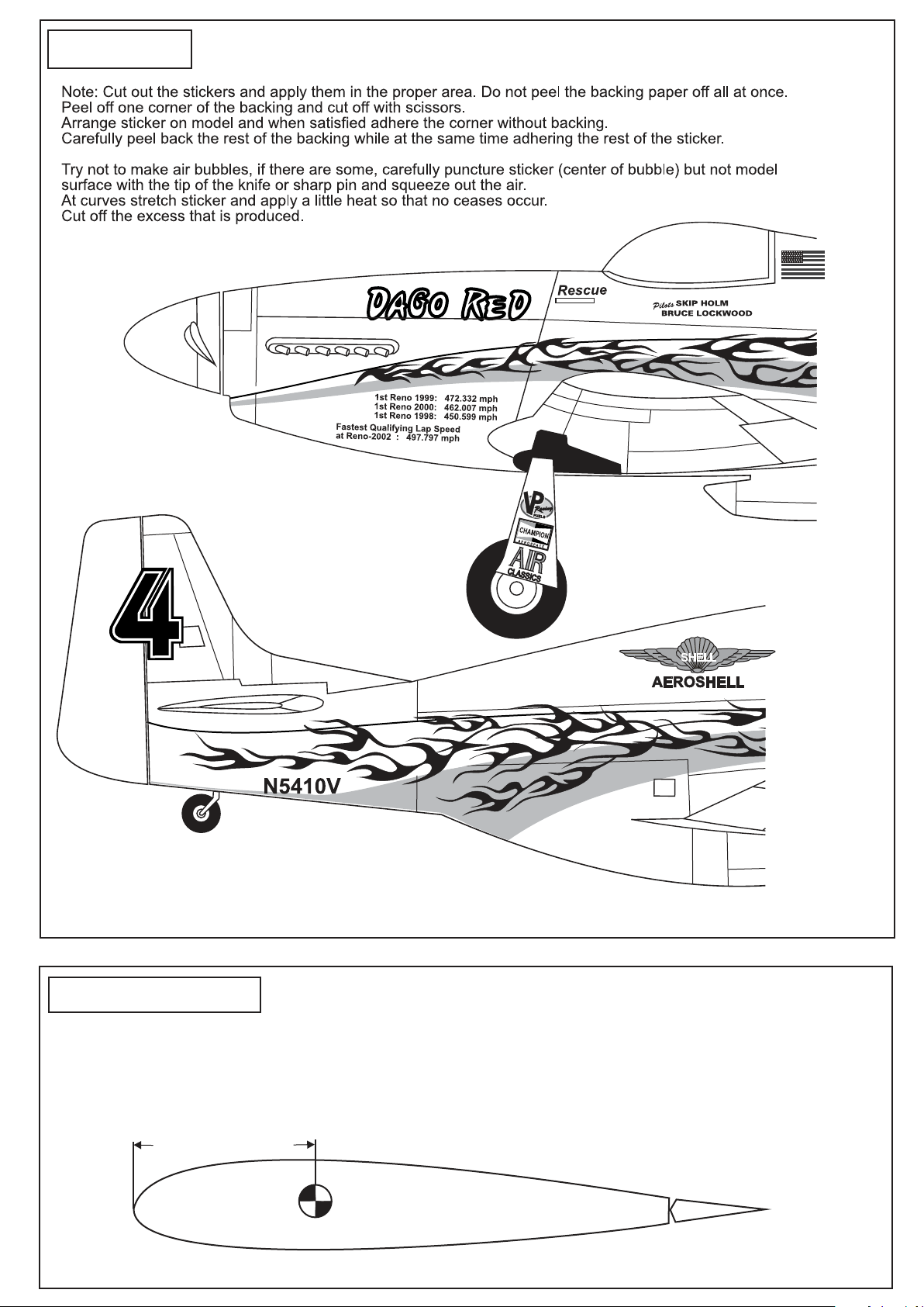
28- Decor
29- Balance
5-13/64” (132mm)
DO NOT try to fly an out-of-balance model !
Note: If necessary, move the battery pack or add weight to either the tail
or nose until the correct balance is achieved.
Wing center section
Page 15
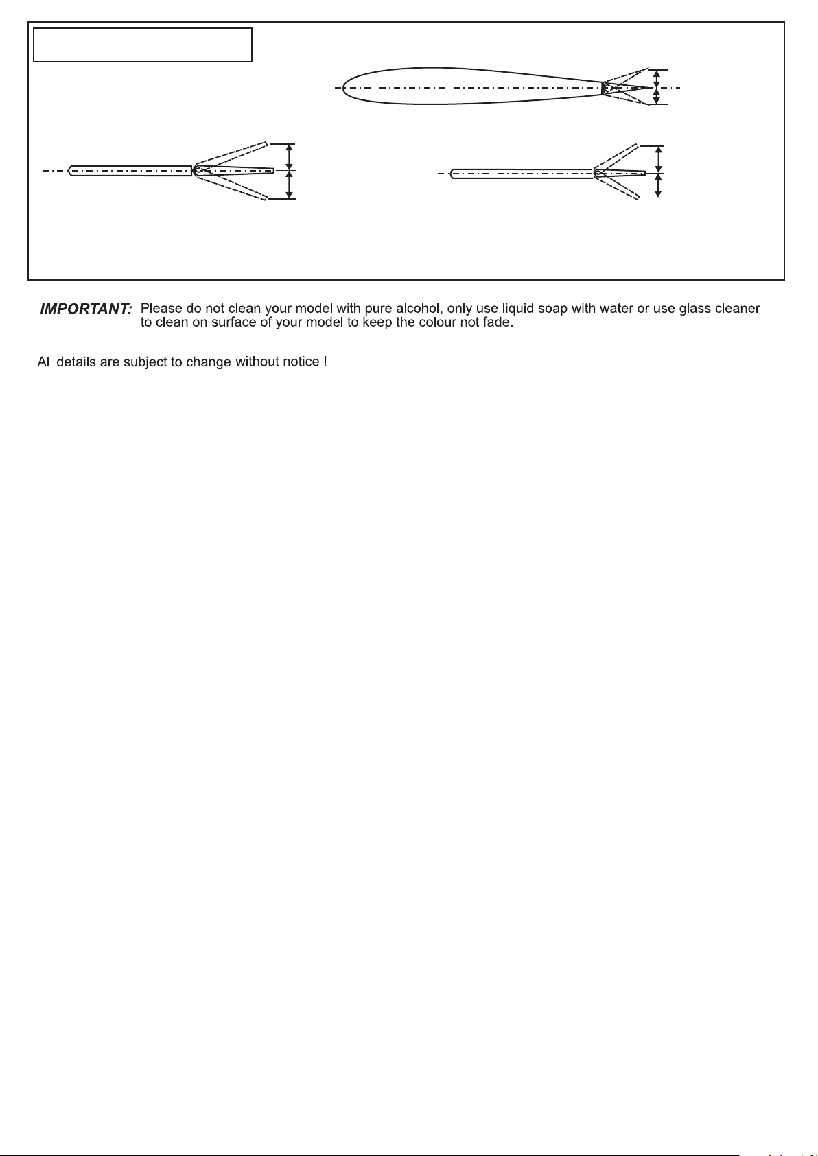
30 Control Surface
15/64”(6mm)
15/64”(6mm)
AILERON STROKE
1-23/64”(35 mm)
1-23/64”(35 mm)
RUDDER STROKE
Adjust the travel of the control surfaces to achieve the values stated in the diagrams.
These value will be suitable for average flight requirements. Adjust the values to suit your particular needs.
ELEVATOR STROKE
13/32”(10mm)
13/32”(10mm)
 Loading...